1. Introduction
Software-defined networking (SDN) [
1,
2] is a centralized, revolutionized technology for alternative network management control, which separates network operations into the control plane and the data plane [
3,
4]. The controller controls the packet forwarding route through the control plane using OpenFlow protocol [
5,
6] and packets are transmitted among switches through the data plane. Relying on the information of network usages collected from all switches, the controller is able to efficiently provide a forwarding decision for each flow. In addition to define the mechanism for forwarding rules composition, the OpenFlow protocol also provides the way to deal with the incoming packets over the switch, such as to modify the destination IP address, to change the source MAC address, or to be associated with a VLAN ID. Multiple actions, called an action set, can also be defined to control SDN network operations.
As in SDN networks, the switch always refers the flow entries to forward the flow packet; when and how to manage the flow table is critical in forwarding efficiency. In the flow table, each flow entry defines a forwarding rule, which specifies the switch of the next hop and actions of how to deal with the packet. The approach of deploying flow entries can be either a proactive mode or reactive mode [
7]. In the proactive mode, the controller determines the forwarding path before the arrival of a packet by writing the forwarding rules into the flow tables in advance. When a packet arrives, the switch simply follows the forwarding rule to transmit the packet. The forwarding policy of the proactive mode is similar to traditional IP network routing, MPLS [
8], or segment routing [
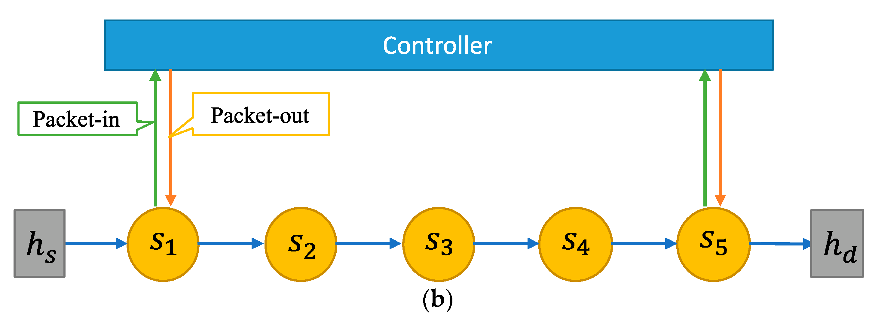
9]. The proactive mode operations are suitable for a static network environment where routing paths are not frequently adjusted. In reactive mode SDN, upon the arrival of a packet, the flow table at the switch is inspected, and if there is an entry associated with the packet’s destination, the packet is forwarded accordingly. Otherwise, the switch sends a query request, called a packet-in message, to the controller for forwarding determination. Upon receiving a packet-in packet, the controller returns a packet-out message to the switch, which installs a flow entry to the flow table at the switch. Consequently, the pending packet can be successfully transmitted following the forwarding rule. The forwarding route management at the controller enhances the capability of balancing the network resource usage. Opposed to the proactive mode, the operations of the reactive mode are more suitable for the dynamic network environment.
Most current data centers involve dynamic virtual machines connection to provide network services; the reactive mode SDN is well suited for this frequently changed network environment. However, with the reactive mode operations, the controller requires dialogs for all switches on the forwarding path. The number of dialogs is symmetric to the number of switches. Therefore, issuing forwarding rules for each unfamiliar packet, the controller can easily become a bottleneck. If a packet passes through N switches to reach its destination, there are 2N communications between the controller and switches, which may increase the controller’s loading as N becomes larger. Even though all subsequent packets in a flow may reference an existing flow rule for forwarding without the controller’s interventions, most current network applications, such as social networks IoT [
10], UAV [
11], NIDS [
12], etc., are prone to generate a large volume of unfamiliar flows. The occurrences of unfamiliar flows will certainly increase the traffic load over the controller and hence cause the processing delay. Therefore, for the reactive mode SDN applications to be practical, novel approaches of effectively reducing the packet sojourn time and minimizing the number of packet-in messages deserve further study and development.
Under reactive mode SDN networks, in order to effectively reduce the number of packet-in messages, we borrowed the idea from the tunnel boring machine (TBM) [
13]. A TBM, also known as ‘Mole’, is a machine used to excavate a tunnel with circular cross sections in various solid and rock formations. We adopt the concept of tunnel excavation to establish forwarding paths. As the TBM is placed at the entrance of a tunnel, the machine excavates a hole following the scheduled trail until it reaches the exit. When a switch first connects to the controller asking for an unfamiliar packet transmission, which is similar to the initial setup for TBM at the entrance, the controller generates forwarding rules for the switches along the path. Meanwhile, the packet is temporarily buffered at the controller until the tunnel is passed through. In other words, we emulate the tunnel penetration technique to establish a forwarding path and propose a mechanism called the SDN tunnel boring machine (SDN-TBM). The idea is to leave the first packet of a flow at the controller until the forwarding path is established, while only the boring packet (BP), which contains forwarding rules and actions, is transmitted over the switches along the path. Consequently, all intermediate switches can be waived from the sending packet-in messages to the controller.
The rest of the paper is organized as follows. Related work is given in
Section 2. The architecture and operations of SDN-TBM are presented in
Section 3. In
Section 4, an M/M/1 queuing model is developed for the system performance. The evaluation results are then reported, and conclusions are given.
2. Related Work
In the study of reactive mode SDN networks, several efforts have been presented to reduce the controller’s load, such as multiple controllers, flow entries merge, and MPLS label switching. Ma et al. [
14] proposed a meta controller (MC), which is based on building a manager for several controllers to control SDN operations in a decentralized manner. The key idea of multiple controllers is to redistribute switch–controller association to offload the overloaded controllers. Meta controllers may reduce the load over the control plane but could also increase the overall bandwidth usage. Neghabi et al. [
15] surveyed several multi-controller proposals. Most of the proposed approaches focus on controllers’ load balancing. Generally, the multi-controller approach may distribute the load, but it is costly and may suffer from low scalability and low availability, as well as high complexity. Moreover, the multi-controller approach may not be able to reduce packet-in messages.
Flow entries can also be logically merged depending on the tags, as reported by MacDavid et al. [
16]. They proposed PathSets, which uses a compression encoding scheme to insert a compact tag into packet header. By the increased probability of flow matching, the merging approach can be effective to reduce the number of packet-in messages. However, the forwarding route may lack flexibility due to the invariant bundle of flow rules. This approach is suitable for data centers with stable network topology but is not for topology with frequent changes.
One other approach to reduce the number of packet-in messages is to adopt the concept of label switching as in MPLS [
17,
18,
19,
20]. Under the MPLS-based approach, routing information is encoded by the 12-bits VLAN identifier (VID). When a packet enters its ingress switch, it is encapsulated with multiple port numbers, which map to the forwarding switches on the route. Intermediate switches will use the VID to forward the packet to the next hop and delete the used header until the packet is delivered to its final destination. The VID field can record 3–5 hops. The scheme cannot need the controller service when receiving an unfamiliar packet, except for ingress switch. Therefore, it effectively reduces the number of packet-in messages. However, the switches may only forward packets (or flows) to designated ports but be unable to perform more actions for dealing with the packets. Consequently, the ability of forwarding the packet is restricted, such as changing the source or the destination MAC or IP addresses. Hence, even though the MPLS-based approach can solve the controller’s overloading problem, SDN features may not be fully implemented.
Once the first packet-in message of a flow has been received by the controller and a forwarding path has been determined, the controller may send packet-out messages to all intermediate switches. It seems that this approach may be effective in reducing the number of packet-in messages. However, the arrival of the packet-out message may be later than the arrival of a subsequent packet over the switch, which may cause the switch to send packet-in messages. Hu et al. proposed a scheme called Softring [
21] to allow the packet to stay in a circular route at the switch to avoid unnecessary packet-in requests. However, this approach requires extra processing time and extra space to deal with the packet at the switch, which causes an overhead to the switch. We briefly explain the pros and cons of the SDN-TBM mechanism compared to other solutions in
Table 1.
3. Design of SDN-TBM
As in reactive mode SDN networks, when an unfamiliar packet arrives at a switch, the switch issues a packet-in message to the controller, waits for a forwarding instruction from the controller, and resumes its packet forwarding process. All intermediate switches along the route to the destination follow the similar interactions with the controller, which results in a severe delay and a large number of communications involved. In our proposed approach, only the first and the final switches along the forwarding route are required to connect to the controller, while a light packet, called a boring packet (BP), including only the requisite information for packet forwarding is transmitted between switches. The use of boring packets is different to the circular route design in Softring, which allows all intermediate switches along the path to be free in communication with the controller for transmitting a service flow.
3.1. Overview of SDN-TBM Operations
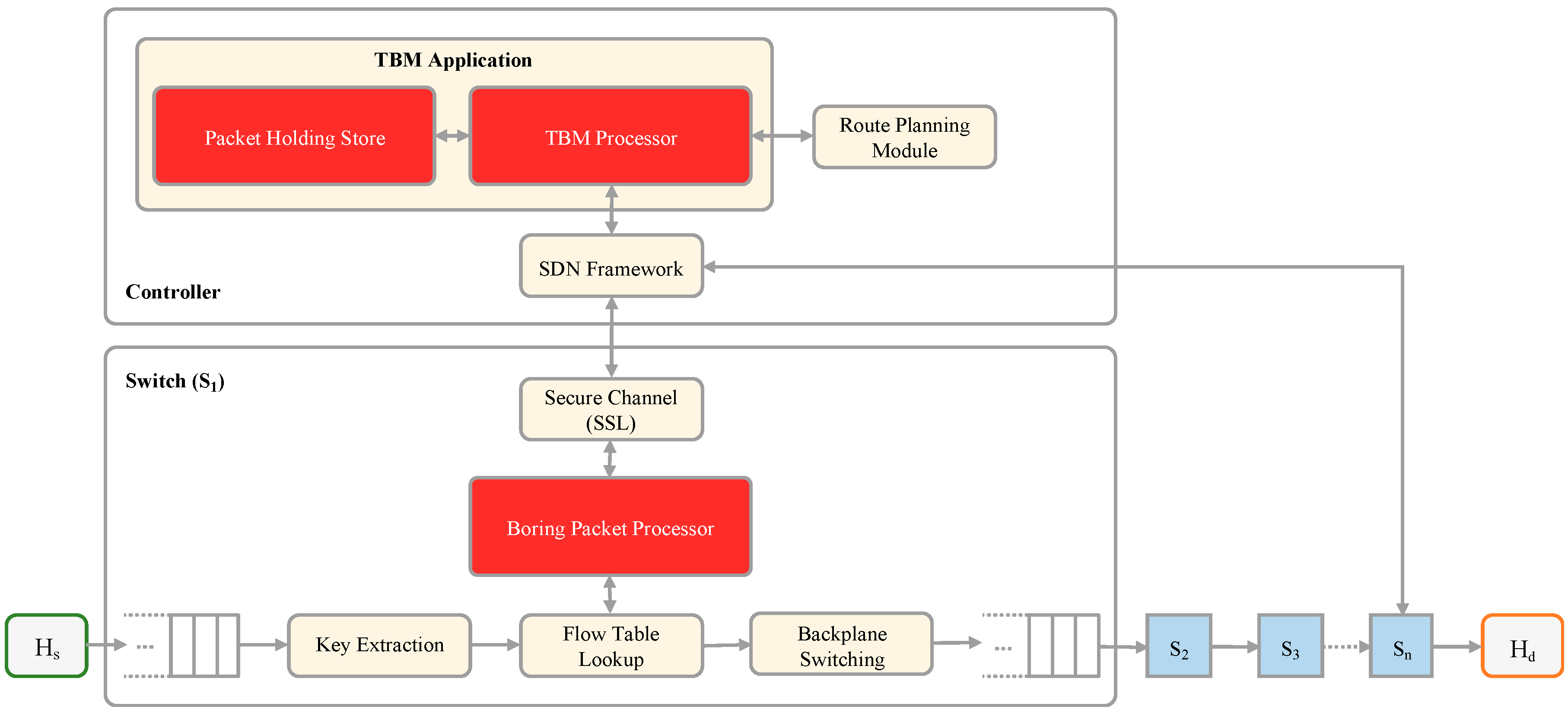
Other than conventional SDN functions, the SDN-TBM system adds three functional modules to enable the boring packet processing: boring packet processor (BPP), TBM processor (TBMP), and packet holding store (PHS), as shown in
Figure 1 of the SDN-TBM architecture. BPP is included in each OpenFlow switch and plays the role of both packet-in message transmitter and boring packet resolver, while TBMP and PHS are extra modules added to the controller. TBMP is the core logic of SDN-TBM, which stores the to-be-delivered packets in PHS and generates boring packets. A to-be-delivered packet is the first packet in a flow, which is temporarily kept in the controller and is delivered when the tunnel has been completely set up. PHS is a database which stores the to-be-delivered packets and the relevant information, such as timestamp, action set, etc.
When an unfamiliar flow arrives at the switch, BPP forwards a packet-in message to the controller for the first packet. The packet is passed through BPP to the controller. TBMP on the controller receives the packet-in message and stores it to PHS. The header of the packet is sent to the route planning module for forwarding the path calculation. Once the forwarding rules are determined, the information is provided to TBMP to construct a boring packet (BP). BP, as carried by a packet-out message, is then sent back to the initiated switch. BP consists of the forwarding rules as in action sets for all intermediate switches. Once receiving the BP, the switch updates the flow table and forwards the boring packet to the next switch hop. The next hop switch treats the BP as an unfamiliar packet and issues a packet-in message. However, BPP in the intermediate switch deals with the BP without sending to the controller, instead, it creates a packet-out boring packet. The flow entry carried by this packet-out BP are then written to the flow table. Meanwhile, the BP is further forwarded to the next switch hop. This procedure continues repeatedly until BP reaches the final switch which the destination host is associated.
When the BP arrives at the last switch, which is the egress switch on the forwarding path, a packet-in boring packet is sent to the controller through the boring packet processor. TBMP in the controller extracts the matched to-be-delivered packet in PHS and constructs a complete packet-out packet, which is the original packet, and returns to the egress switch. Once the first packet of a flow has been successfully delivered, the forwarding tables of intermediate switches along the forwarding path are already updated. All subsequent data packets of the same flow are forwarded accordingly without interventions with the controller.
3.2. Operations at the Controller
Other than built-in SDN framework modules, such as the route planning module, SDN-TBM includes two more modules, packet holding store (PHS) and TBM processor (TBMP), as shown in
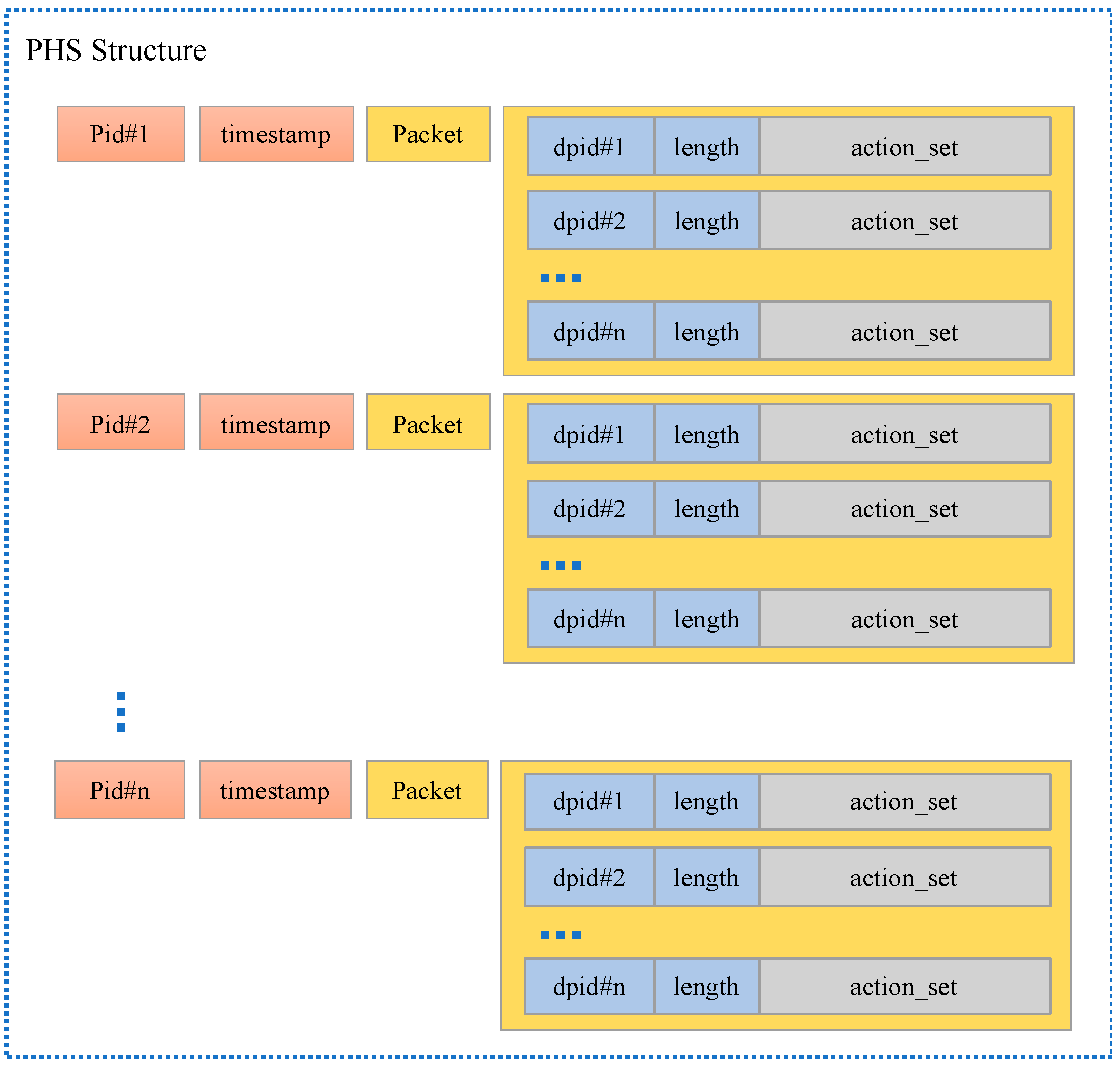
Figure 1. TBMP communicates with built-in modules and stores the packet into PHS. TBMP is also responsible for generating a packet-out message, either containing a boring packet (BP) or a regular message. PHS stores to-be-delivered packets, including the information of the packet id, timestamp, action_set, and payload for each holding packet. As shown in
Figure 2, PID denotes the packet identifier of the to-be-delivered packet, timestamp records the creation time, and action_set records the sequence of actions to be applied to the switch on the forwarding path. For each associated switch, there is an entry including a tag of boring packet, the switch identifier, dbid (or switch id), length of action-set, and action-set. The data structure of the boring packet contains the header portions, which are inherited from the original packet, and payload portions, which consist of tag, dbid, length, and actions, as can be shown in
Figure 3.
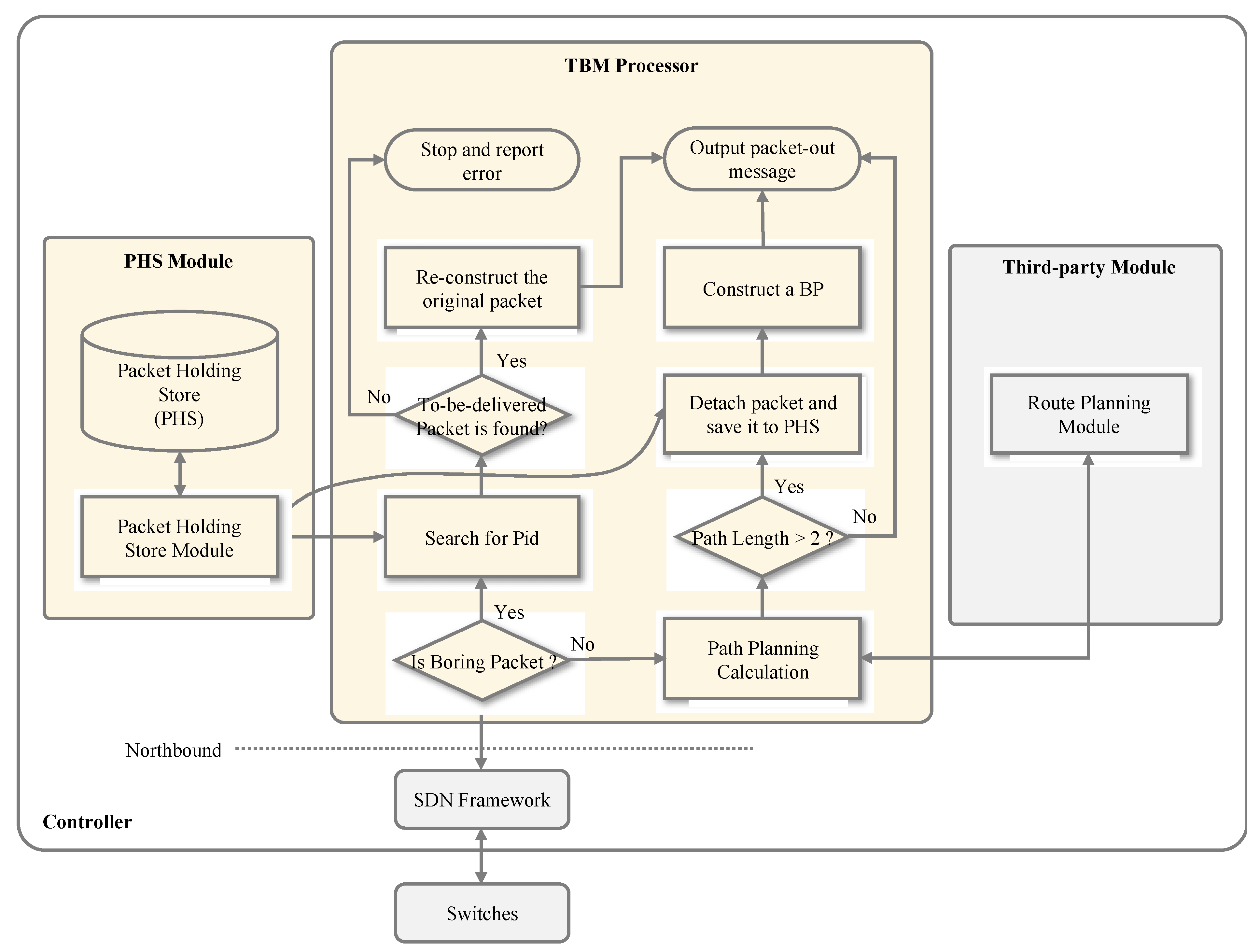
The TBMP module plays the central role of SDN-TBM, which performs the core logic for dealing with the packet management at the controller. When a packet is received by the controller, the step-by-step operations of TBMP are described in the following, as supplemented in
Figure 4.
- Step 1:
Check whether the incoming packet is a BP or not. If it is a BP, then jump to step 6, otherwise, proceed to step 2.
- Step 2:
Calculate the forwarding path. The calculation of forwarding path requires interactions with the route planning module in the third-party modules. Forwarding rules for the switches along the path are also determined.
- Step 3:
Check the number of hops. If the number of hops is 2, a packet-out packet is constructed and is returned back to the switch as regular SDN workflow. Otherwise, prepare to build a boring packet.
- Step 4:
Store the packet into PHS. If there are more than 2 switch hops in the forwarding path, the packet is temporarily saved in the packet holding store together with relevant forwarding rules. The packet header is extracted for the purpose of generating a boring packet.
- Step 5:
Generate a packet-out boring packet. Following the saving of the packet, a boring packet is constructed by including the header and all action-sets, as determined in step 2. This packet includes the boring packet identification as well as the identification of to-be-delivered packet, which is previous stored in PHS.
- Step 6:
Search for stored packet in PHS. It assumes that the incoming packet is a boring packet. This is the case that the last switch in the path sends the packet-in message and asks for the original complete packet. Pid is used as the key to search for the to-be-delivered packet.
- Step 7:
Is the to-be-delivered packet found? If the target Pid is not matched, the searching process fails, and an error is reported. Otherwise, the original packet is ready to be re-constructed.
- Step 8:
Replace the BP with original packet to form the packet-out packet. A packet-out message is generated by replacing the BP with the original packet and is returned to the last switch as listed in the boring packet.
The packet holding store (PHS) interacts with the tunnel boring machine processor (TBMP) in two occasions: store the packet before generating a boring packet and retrieve the to-be-delivered packet to construct a packet-out message for the final switch. A packet identifier is created when the packet is stored in PHS, and this identifier is used as an index to search for to-be-delivered packets in the database.
Through the operations at the controller, SDN-TBM differentiates between a regular packet-in packet and a boring packet and generates a packet-out boring packet. Under SDN-TBM, only the switch receiving the first packet from a new flow and the last switch of the forwarding path may send a packet-in packet to the controller; all intermediate switches along the route will not be in touch with the controller.
3.3. Operations at the Switches
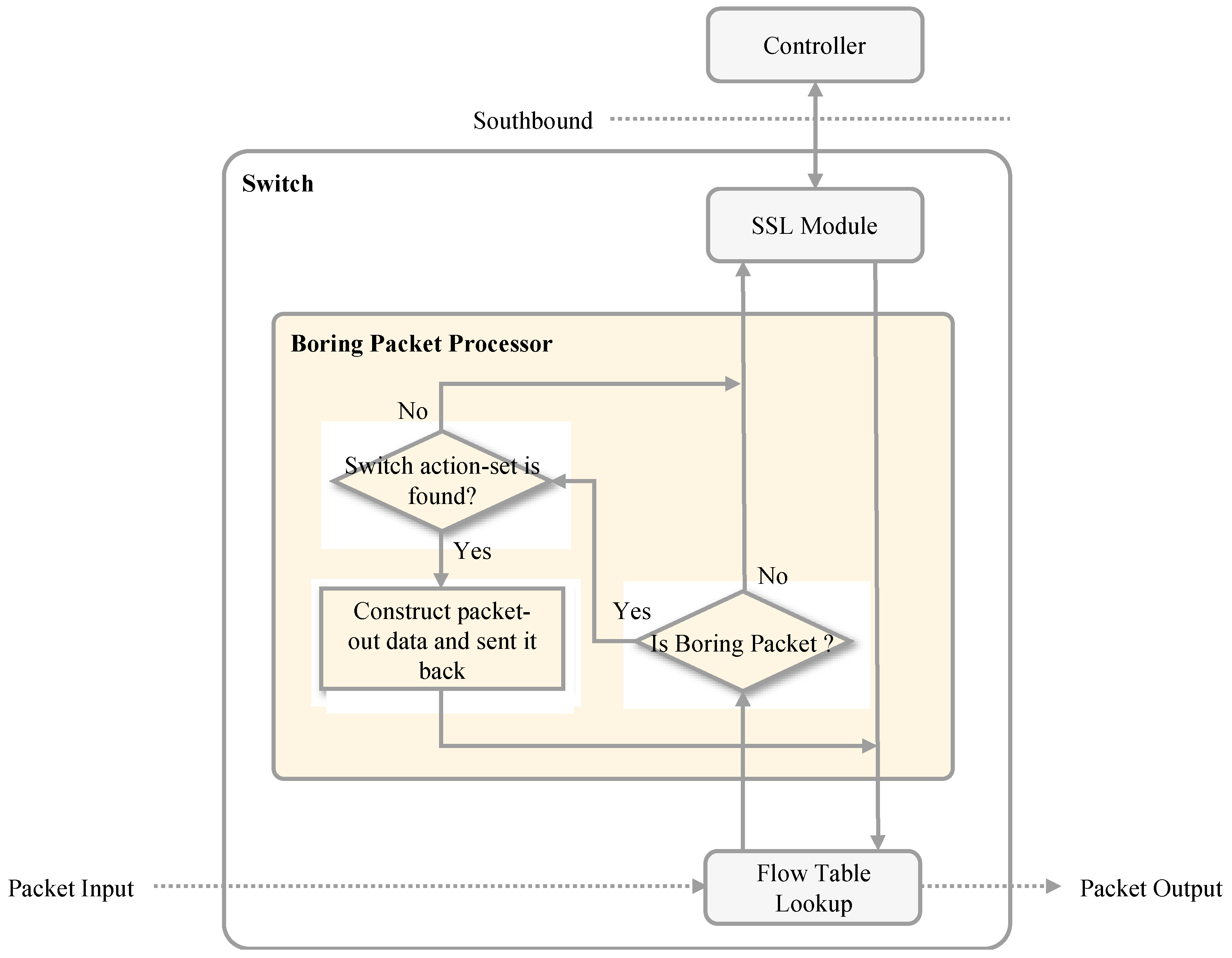
An SDN-TBM-enabled system requires the boring packet processor (BPP) to be included in each participating switch. BBP is a functional module that deals with packet-in and packet-out messages, particularly the boring packets. As shown in
Figure 5, once a packet arrives at a switch, there is normal packet forwarding if it is matched packet. Otherwise, it fails in searching for a match in flow table, a packet-in message is generated and it is passed to BPP for boring packet inspection. If the arriving packet is not a boring packet, then it is simply forwarded to the controller and waits for a packet-out message sent from the controller. For the purpose of consistent processing, a packet-in message is always passed to the boring packet processor (BPP). When a packet-out boring packet is received by the switch, the switch retrieves the flow entry and updates the flow table. Accordingly, the boring packet is then forwarded to the next hop.
When the BP is received at the next hop switch, the receiving switch routinely looks for a match in the flow table. An unsuccessful match results in generating a packet-in message, and it is sent to a boring packet processor (BPP). After being sure that the packet is a BP, BPP extracts the flow entry for this switch and generates a packet-out message which contains the boring packet. Subsequently, the flow table is updated, and the boring packet is forwarding accordingly. This procedure continues until the BP reaches the last switch.
The last switch requires a special processing for receiving the boring packet. When the BPP at the last switch discovers that it is the final hop in the forwarding path, it transforms the packet-in boring packet to the controller without flow entry update being executed. The controller receiving the packet-in boring packet will reconstruct the original packet and send it as a packet-out packet to the switch. Hence, the last switch is able to directly send the packet to the associated destination host.
3.4. Security Discussion
The most worrisome aspect of the SDN-TBM mechanism is the modification of forwarding rules in BP packets. A hacker who can add, modify, or remove traffic rules from a switch by modifying BP packets can lead to incorrect forwarding behavior on the data plane. Therefore, a hacker may modify BP packets. First, we assume that the controller is secure and that the communication between the switch and the controller is secure. In this way, a hacker can only intercept BP packets on the network link of the data plane or at the switch. In a high control, high security data center, it is difficult to intercept the network link to listen for packets. Moreover, BP packets are only delivered on a certain path, and a hacker cannot listen to all BP packets. If hackers can do so in the data plane, it also means that the IDC is no longer secure. In addition, a hacker can emulate BP packets and inject them into the data platform through the source host. The SDN-TBM mechanism will treat the emulated packets as normal packets and faithfully deliver them to the destination host. This is because such emulated packets cannot be used by the switch’s BP module to change the traffic rules. Therefore, we believe that the SDN-TBM mechanism does not increase the risk of attacks on SDN networks.
4. Analysis Model
In this section, following previous studies [
22,
23,
24,
25,
26,
27,
28,
29], we develop the corresponding queuing models, shown in
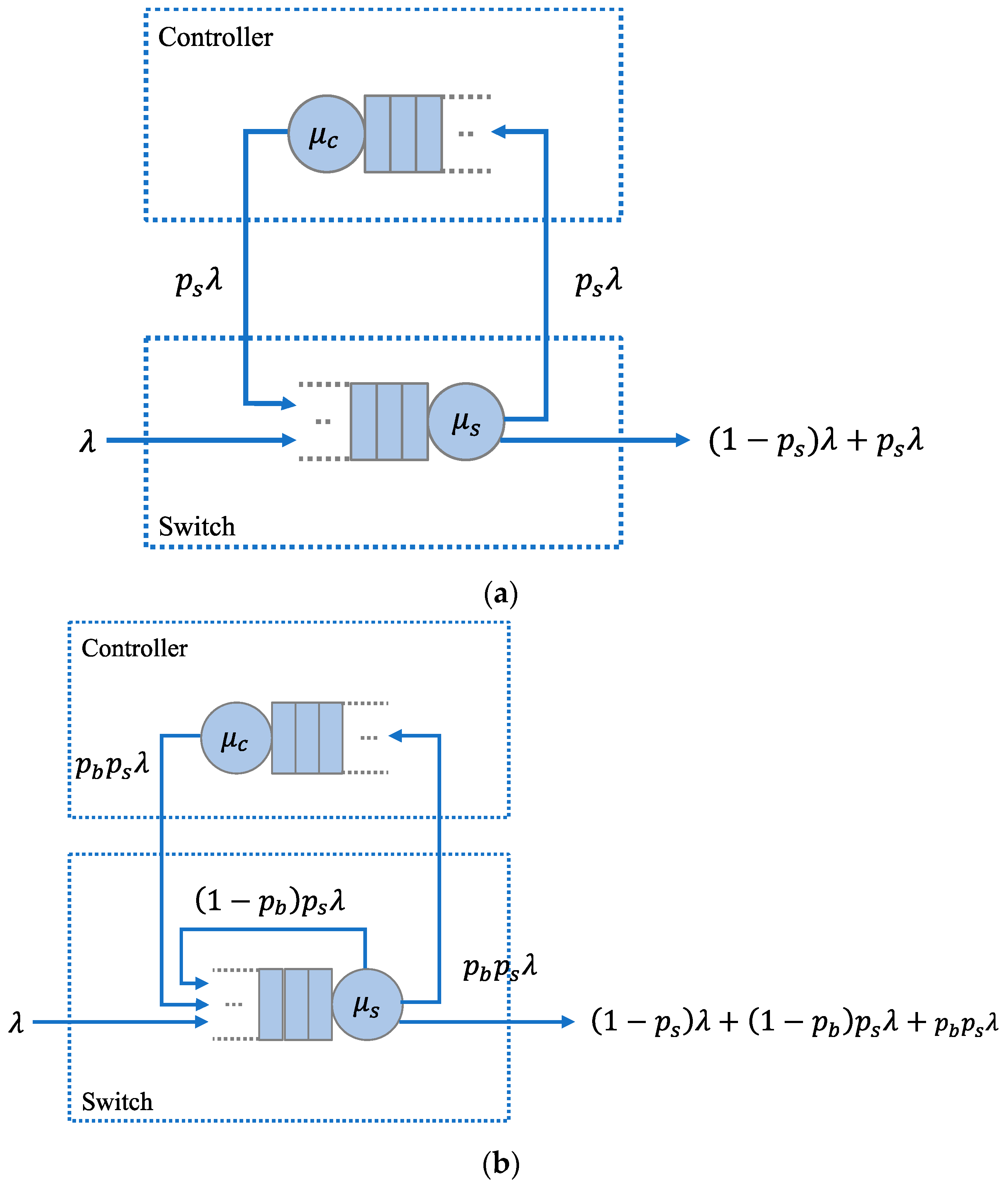
Figure 6, to analyze the average sojourn time of an external packet (EP) passing through the conventional SDN and the proposed SDN-TBM networks. For both queuing models, we assume that both switch and controller are Markovian servers, and the service time of the controller incorporates the two-way transmission time between the switch and the controller. The overall traffic process at the switch and the controller follows the Poisson process, and two processes occur in different time slots. In addition, two infinite buffers are deployed in the switch and the controller. Following [
22], we model the operation of a switch by using an M/M/1 queue while the operation of a controller is modeled using an M/G/1 queue.
Table 2 defines the notation we use in this paper.
We first discuss the scenario of an EP arriving at a switch. For the conventional SDN network, as shown in
Figure 6a, we assume that λ denotes the arriving rate of an EP arriving at a switch according to a Poisson distribution,
represents the service rate of the switch,
denotes the service rate of the controller, and
represents the probability that a packet is forwarded to the controller. When an EP arrives at a switch and finds no flow entry matched in the flow table, it is forwarded to the controller
. Otherwise, the EP is forwarded to the next hop
.
For the SDN-TBM network, as depicted in
Figure 6b, we assume that λ denotes the arriving rate of an EP arriving at the switch according to a Poisson distribution,
denotes the service rate of the switch. We also let
represent the probability of forwarding the non-boring packets (BPs) to the controller, and
denotes the service rate of the controller. When an EP, which is not a BP, arrives at a switch and finds no flow entry matching in the flow table, it is forwarded to the controller
. Otherwise, the packet is processed by the BPP, and then the processed packet is sent directly to the same switch
.
Next, we derive the average sojourn time of an EP for both models. Let
and
denote the sojourn time of the packet-in message in the switch and the BPP, respectively.
and
can be expressed as follows
Let
and
denote the sojourn time of a packet in the controller in the SDN and SDN-TBM mechanisms, respectively.
and
can be expressed as follows:
The total sojourn time
of a packet entering the SDN network and the total sojourn time
of a packet entering the SDN-TBM network can be respectively expressed as follows:
Note that
represents the sojourn time of a packet in the switch, where the packet is retransmitted to the same switch after processing by BPP. We assume that
is equal to
. Therefore, we can calculate the mean of
and
according to the following expressions:
By substituting Equations (1)–(4) into Equations (7) and (8), we can obtain
and
as follows:
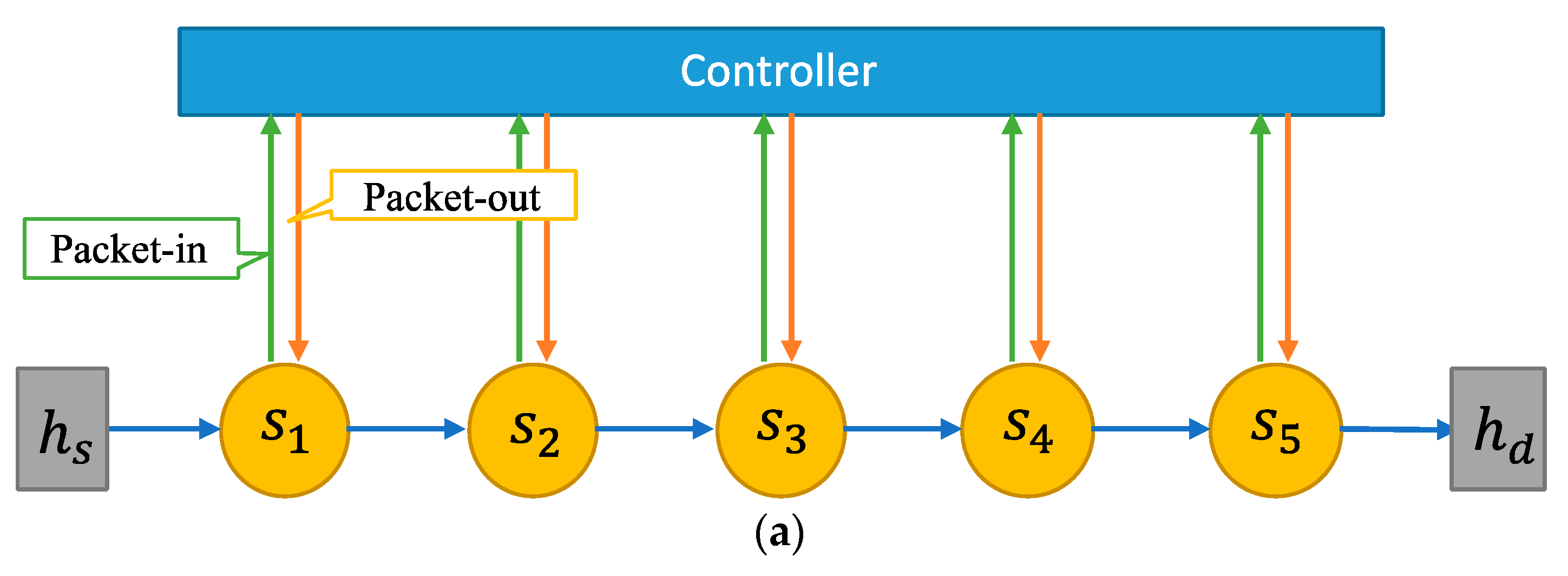
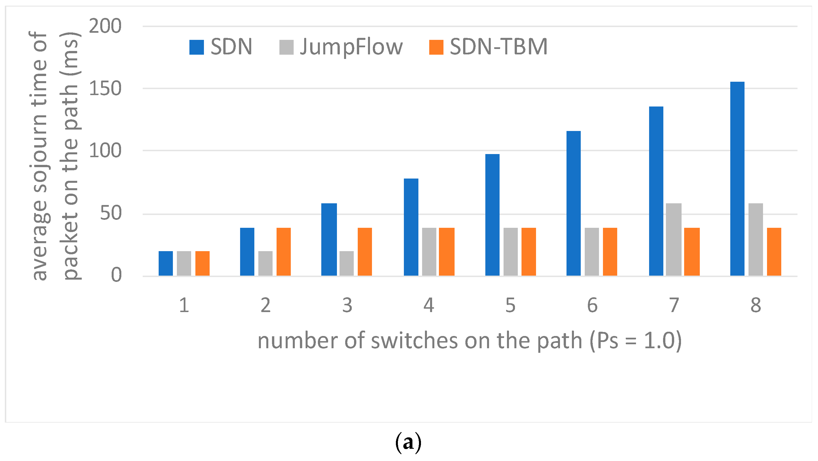
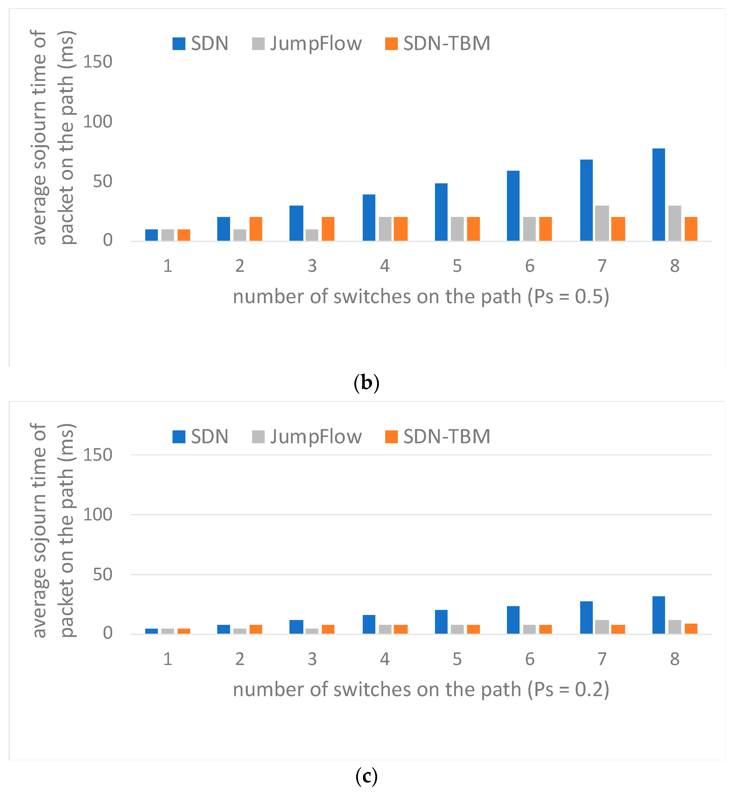
Next, we analyze the average sojourn time of a packet passing through multiple switches for both networks. For convenience, we do not consider the transmission time of the link because the transmission time of the link is extremely short. Only the processing time of the switch and the controller is considered.
Figure 7 shows the operation flow of a packet arriving at conventional SDN and SDN-TBM networks. We assume that the number of switches on the transmission path of the packet from the source to the destination is
. For the conventional SDN network illustrated in
Figure 7a, each switch operates independently, and the controller communicates with each switch individually when an unfamiliar packet is encountered. A switch communicates with the controller when it receives an unfamiliar packet. On the other hand, for the SDN-TBM model illustrated in
Figure 7b, only the first and last switches on the transmission path will directly communicate with the controller as an unfamiliar packet is encountered. Therefore, the value of
is equal to
. The total average sojourn time of a packet passing through multiple switches for both networks,
is calculated as follows:
where
represents the total number of switches in the flow path, and
represents one flow packet.


