Article

Longitudinal Wave Locally Resonant Band Gaps in Metamaterial-Based Elastic Rods Comprising Multi-Degree-of-Freedom DAVI Resonators

School of Mechanical Engineering and Automation, Fuzhou University, Fuzhou 350116, China
*
Author to whom correspondence should be addressed.
Symmetry 2022, 14(5), 1030; https://doi.org/10.3390/sym14051030
Submission received: 15 April 2022 / Revised: 6 May 2022 / Accepted: 12 May 2022 / Published: 18 May 2022
(This article belongs to the Section Engineering and Materials)

Abstract

:
The wave propagation and vibration transmission in metamaterial-based elastic rods with periodically attached multi-degree-of-freedom (MDOF) dynamic anti-resonant vibration isolator (DAVI) resonators are investigated. A methodology based on a combination of the transfer matrix (TM) method and the Bloch theorem is developed, yielding an explicit formulation for the complex band structure calculation. The bandgap behavior of the periodic structure arrayed with single-degree-of-freedom (SDOF) DAVI resonators and two-degree-of-freedom (2DOF) DAVI resonators are investigated, respectively. A comparative study indicates that the structure consisting of SDOF DAVI resonators periodically jointed on the metamaterial-based elastic rod can obtain an initial locally resonant band gap 500 Hz smaller than the one given in the published literature. The periodic structure containing 2DOF DAVI resonators has an advantage over the periodic structure with SDOF DAVI resonators in achieving two resonance band gaps. By analyzing the equivalent dynamic mass of a DAVI resonator, the underlying mechanism of achieving a lower initial locally resonant band gap by this periodic structure is revealed. The parameters of the 2DOF DAVI resonator are optimized to obtain the lowest band gap of the periodic structure. The numerical results show that, with the optimal 2DOF DAVI parameters, the periodic structure can generate a much lower initial locally resonant band gap compared with the case before the optimization.

1. Introduction

In the last two decades, extensive efforts have been devoted to the study of phononic crystals (PCs) which are made of artificial periodic composite materials and contain a periodic array of acoustic scatters embedded in a matrix material [1,2,3,4]. The wave filtering behavior of PCs is the most appealing feature, as it ensures some frequency ranges known as band gaps or stop bands. The harmonic elastic wave cannot propagate freely inside these band gaps.
Currently, there are two kinds of mechanisms for phononic crystals to generate band gaps, namely the Bragg scattering mechanism and the localized resonance (LR) mechanism [4]. As for the Bragg type, the main reason for the band gaps is the mutual coupling characteristic of the elastic waves and the periodic variation of materials. The center frequency of the minimum band gap is about c / 2 a , where c is the speed of the elastic wave in the matrix material and a is the lattice constant of the periodic structure. Since the wave speeds of most media are very large, it is impossible for the Bragg gaps to insulate low-frequency waves unless a is very large, which is impractical in the general case. The locally resonant mechanism proposed by Liu et al. [5] in 2000, on the other hand, can solve this issue. They developed 3D PCs made up of a cubic array of coated spheres immersed in an epoxy matrix. They can get a band gap in a lower frequency range than the one given by the Bragg type. This pioneering work has triggered many studies in this field [6,7,8,9,10,11,12]. In recent years, acoustic metamaterials (AMs) have become a new field of PCs [13,14,15,16,17]. AMs have remarkable properties such as negative effective modulus or mass, negative refraction acoustic cloaking, and high sound absorbing coefficients with membrane [15,16,17,18,19,20,21,22].
Localized resonant structures will always be introduced into matrix materials when making LR PCs and AMs. This kind of structure can be applied in the vibration isolation of rods, beams, plates, shells, etc. Wang et al. [23] proposed a system consisting of a uniform rod with a multi-degree-of-freedom (MDOF) spring mass resonator, which demonstrates a considerable vibration attenuation within the resonance band gaps. Xiao et al. [24] investigated the same system but with two-degree-of-freedom (2DOF) spring mass resonators. They discovered that their structures can create two band gaps or broadband gaps in the metamaterial-based rod, and the band gap generation mechanisms are also investigated using analytical and physical models that provide explicit equations to determine the band edge frequencies of all the band gaps. However, these band gaps are usually located in the high frequency range; for example, the initial frequency of the first bandgap of the period structure proposed by Wang is beyond 1500 Hz. Whereas in practice it is desirable to attenuate elastic waves at low frequencies with a low mass ratio. Song et al. [25] used a periodically layered isolator to suppress the vibration from a propeller-shaft to the hull of an underwater vehicle system in which the isolation frequency range is located in several tens of Hz to hundreds of Hz. Zhou et al. [26,27,28,29,30] developed some types of nonlinear isolators as resonators to attenuate the longitudinal and flexural waves in beams in the low frequency range (a few tens of Hz). While the nonlinear isolator usually has stability problems, the dynamic anti-resonance vibration isolator (DAVI) proposed by Flannelly [31] may generate a substantially lower resonance frequency with the same stiffness and mass as a typical spring mass system because of its inertial amplification mechanism. Inspired by this, and to yield multiple band gaps, this paper uses a multi-degree-of-freedom (MDOF) DAVI as a resonator and investigates its isolation performance. This paper aims to propose DAVI as a resonator and expects it to generate much lower initial frequency band gaps when it is arranged in the periodic structure than the traditional resonators with the equivalent parameters. Then, this paper aims to clarify its underlying mechanism. This is very important in the area of low frequency vibration control, such as in the aforementioned propeller-shafting vibration control problem. Parameter optimization for the periodic structure with 2DOF DAVI resonators will be examined in detail to further reduce the initial frequency of the band gaps.
This paper is organized as follows: Section 2 deduces the band gap formulations for the infinite periodic structure and the vibration transmission through finite structures which are joined with an MDOF DAVI as a resonator. Then, the difference in the band gap generation mechanism between the periodic structure with the DAVI resonator and spring mass resonator is revealed by introducing a parameter called equivalent dynamic mass. Section 3 gives two numerical examples to illustrate the band behavior of the structure periodically arrayed with DAVI. Comparisons between the present study and a published study are also conducted. Then, the multi-island genetic algorithm (MIGA) method is used to optimize the resonators. The conclusions are given in Section 4.

2. The Model and Bandwidth Formulations

As mentioned in the Introduction, to explore the potential of the application of the metamaterial-based rod periodic structure in the low frequency vibration control area, this paper proposes the use of MDOF DAVIs as resonators to study its longitudinal wave attenuation properties in a rod. In this paper, we mainly give a theoretical discussion of this topic.
The dynamic anti-resonant vibration isolator (DAVI) was firstly proposed by Flannelly [31] in the 1960s to meet the strict requirements of stiffness and mass of the isolator in the aerospace industry. The schematic diagram of a DAVI is shown in Figure 1.
Due to the introduction of the lever, the natural frequency of the system will be greatly reduced. According to the published literature [24], the sharp attenuation in the locally resonant band gap corresponds to the natural frequency of the resonator. This shows the potential of the DAVI to be a resonator to achieve a lower initial locally resonant band gap without increasing its mass.
In this section, the formulae of the band gaps of the infinite periodic structure with MDOF DAVI is given. Secondly, due to the infinite periodic structure, it cannot be realized in practice; therefore, the vibration transmissibility of a finite periodic structure with an MDOF DAVI is studied.

2.1. Wave Propagation in an Infinite Periodic System

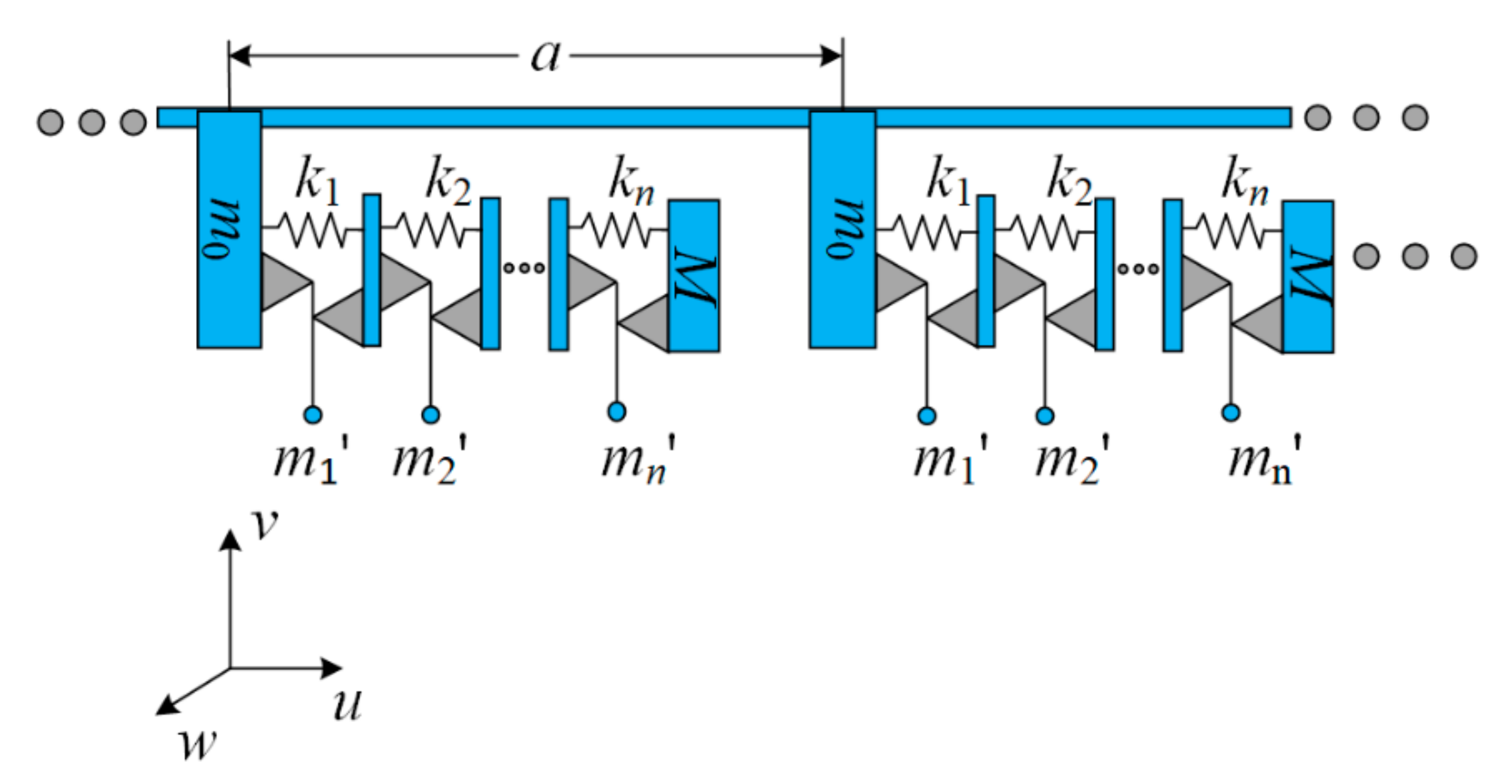
Figure 2 shows an infinite periodic structure periodically arrayed with MDOF DAVI resonators. The resonators’ spacing is a. For the coordinate system shown in the figure, u represents the longitudinal displacement, ν represents the transverse displacement, and w represents the radial displacement of the rod, respectively.
Before the derivation of the equation of motion of the resonators, several assumptions are given as follows:
i.
The connection between the resonator and the rod is rigid and massless, and the lever is massless and rigid;
ii.
The damping and the friction in the hinge are negligible and the spring is massless, linear, and undamped;
iii.
The mass of the stage is negligible and the load mass is rigid;
iv.
The amplitude of the vibration is small.
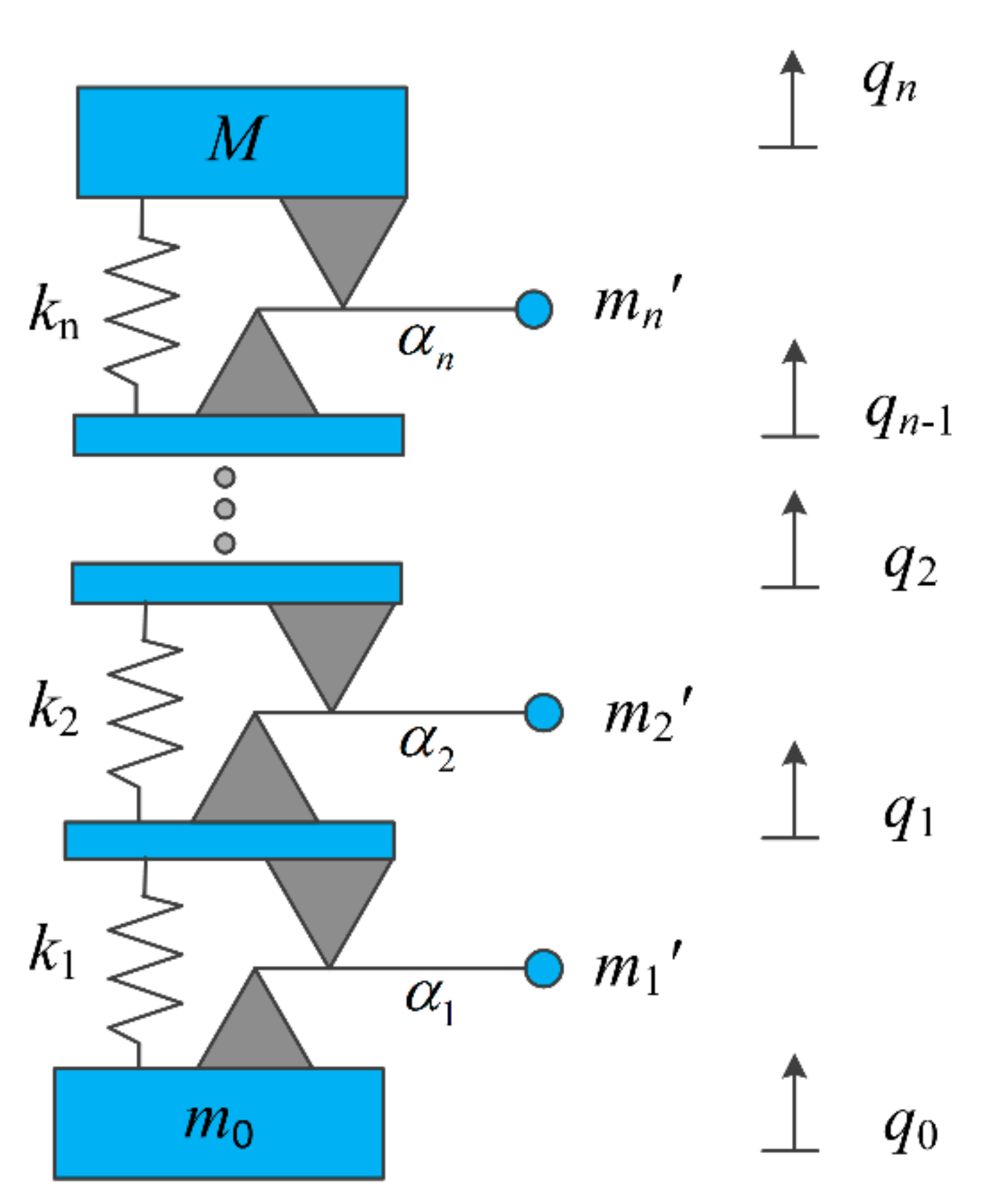
Figure 3 gives a simplified diagram of the resonator in which a resonator comprises n (equals to its degree of freedom) DAVIs. q0 is the displacement of the attachment point, qi (I = 1, 2, 3, …, n) is the displacement of the i-th isolator stage, and αi is the lever ratio of the i-th unit. Each is composed of a series of springs ki, masses m i , lever ratio α i (I = 1, 2, 3, … N), and main mass M. According to the kinematic relationship of the resonator, the kinetic energy, the potential energy of an MDOF DAVI can be given as Equation (1) [32].
T = 1 2 m 0 q ˙ 0 2 + 1 2 m 1 [ ( 1 α 1 ) q ˙ 0 + α 1 q ˙ 1 ] 2 + 1 2 m n [ ( 1 α n ) q ˙ n 1 + α n q ˙ n ] + 1 2 M q ˙ n 2 V = 1 2 k 1 ( q 1 q 0 ) 2 + + 1 2 k n ( q n q n 1 ) 2
The Lagrangian function of the resonator can be deduced as
L = T V = 1 2 m 0 q ˙ 0 2 + 1 2 m 1 [ ( 1 α 1 ) q ˙ 0 + α 1 q ˙ 1 ] 2 + + 1 2 m n [ ( 1 α n ) q ˙ n 1 + α n q ˙ n ] 2 q ˙ 0 2 + 1 2 M q ˙ n 2 1 2 k 1 ( q 1 q 0 ) 2 1 2 k n ( q n q n 1 ) 2
According to the Lagrangian equation for a resonator [33],
d d t ( L q ˙ i ) L q i = F i
where Fi is the corresponding external force on the i-th displacement.
Assuming q i = q i e i ω t and F i = F i e i ω t , qi and Fi are the amplitude of the displacement and external excitation force, i is the imaginary unit, and ω is the excitation circular frequency. Inserting Equation (2) into Equation (3), then the equation can be rearranged in the matrix form as:
( K ω 2 M ) q = F
where the stiffness matrix K and mass matrix M, the vector of freedom q , and forces F are
K = [ k 1 k 1 n k n 1 k n n ] ,   M = [ m 0 + m n ( 1 α 1 ) 2 m 1 n m n 1 m n n ]   , q = [ q 0 q n ]   , F = [ F 0 F n ]
kn1, k1n, and knn in K are given as
k n 1 = k 1 n T = [ k 1 0 0 0 ] ,   k n n = [ k 1 + k 2 k 2 0 0 k 2 k 2 + k 3 0 0 0 0 k n + k n 1 k n 0 0 k n k n ]   ,
mn1, m1n, and mnn in M are given as
m n 1 = m 1 n T = [ m 1 α 1 ( 1 α 1 ) 0 0 0 ] , m n n = [ m 1 α 1 2 + m 2 ( 1 α 2 ) 2 m 2 α 2 ( 1 α 2 ) 0 m 2 α 2 ( 1 α 2 ) m 2 α 2 2 + m 3 ( 1 α 3 ) 2 0 0 0 M + m n α n 2 ]
qn in q and Fn in F are given as
q n = { q 1 q 2 q 3 q n } , F n = { F 1 F 2 F 3 F n }
F0 is the reaction force from the rod at the attachment point denoting the interaction between the rod and the resonator and Fi (I = 1, 2, 3, …, n − 1) is the external force acting on the i-th stage and Fn is the external force from the load mass. If no external force acts on the masses, Fi = 0. Substituting Equation (4) into Equation (3), the following equation can be obtained:
[ k 1 ω 2 [ m 0 + m 1 ( 1 α 1 ) 2 ] k 1 n ω 2 m 1 n k n 1 ω 2 m n 1 k n n ω 2 m n n ] { q 0 q n } = { F 0 0 }
Expanding the matrix in Equation (6), then the relationship between F0 and q0 can be written as
F 0 = S 0 q 0
where S0 represents the resonator’s dynamic stiffness at the attachment point, which can be written as
S 0 = k 1 [ m 0 + ω 2 m 1 ( 1 α 1 ) 2 ] ( k 1 n ω 2 m 1 n ) ( k n n ω 2 m n n ) 1 ( k n 1 ω 2 m n 1 )
Based on the longitudinal vibration theory of the rod, the equation of free motion for the n-th unit cell of the infinite periodic system shown in Figure 2 can be written as [34]
E A 2 u n ( x , t ) y 2 = ρ A 2 u n ( x , t ) t 2
where:
i.
un (x, t) represents the longitudinal displacement at the position x and time t;
ii.
E and ρ are the Young’s modulus and the density of the rod;
iii.
A is the cross-section area of the rod.
The solution of Equation (9) can be obtained by the separation of variables as [34]
u n ( x , t ) = e i ω t { P n + cos h [ i β ( x n a ) ] + P n sin h [ i β ( x n a ) ] ] }
where:
i.
β = ω / c   is the wave number in the rod;
ii.
P n + and P n are constants determined by the boundary conditions.
For the discontinuities condition at the attachment point between the (n − 1)-th unit cell and n-th unit cell, the following formulae can be deduced from the compatibility conditions across the discontinuity point for displacement and the interaction load at the connection point.
  { P n + = P n 1 + cos h [ i β a ] + P n 1 sin h [ i β a ] E A u n ( 0 , t ) x + F 0 = E A u n 1 ( a , t ) x
where P n + = q 0 . Substituting Equation (10) into Equation (12), Equation (12) can be rewritten in a matrix form as
[ 1 0 S 0 i β E A 1 ] [ P n + P n ] = [ cos h ( i β a ) sin h ( i β a ) sin h ( i β a ) cos h ( i β a ) ] [ P n 1 + P n 1 ]
Equation (13) can be further simplified as
K ψ n = H ψ n 1
where
K = [ 1 0 S 0 i β E A 1 ] , H = [ cos h ( i β a ) sin h ( i β a ) sin h ( i β a ) cos h ( i β a ) ] , ψ n = [ P n + , P n ] T ψ n 1 = [ P n 1 + , P n 1 ] T
For the infinite periodic system, the Bloch theorem [35] guarantees that
ψ n = e i q a ψ n 1
where q is the wave vector (for the one-dimensional case, it is also called the wave number and it is scalar).
Substituting Equation (15) into Equation (14), the following equation can be obtained
| T e i q a I | = 0
where T = K 1 H , I is 4 × 4 unit matrix.
By solving the eigenvalue of matrix T, the relationship between q and ω can be obtained, which is the dispersion curve. The sign of q represents the wave transmission in a different direction. Q is a complex number, where the real part of q (Re(q)), which describes the wave’s phase change per unit length, has the property of periodicity and can be confined into [ π / a π / a ] . Hereinafter, it is called the phase constant. The imaginary part of q (Im(q)) depicts the wave attenuation per unit length and its amplitude represents the elastic wave attenuation performance. Hereinafter, it is called the attenuation constant. Therefore, the frequency range can be divided into two parts according to the value of the attenuation constant:
(a)
When 0 R e ( q ) π a and | I m ( q ) | 0 , the corresponding frequency range are band gaps or stop bands, and the phase change of the wave is between 0 and π;
(b)
When 0 R e ( q ) π a and | I m ( q ) | = 0 , the corresponding frequency range are pass bands, and the phase change range of the wave is between 0 and π.

2.2. Vibration Transmission in a Finite Periodic Structure

This subsection is mainly to investigate the vibration transmissibility of a finite periodic structure as shown in Figure 4.
The transfer matrix method is used to obtain this property [36]. It can be seen that the finite structure is excited by a unit harmonic force e i ω t at its left end and its right end is free. Taking advantage of Equation (13), then the boundary conditions can be expressed as
{ E A u 1 ( 0 , t ) x = i E A β P 1 e i ω t = Q P 1 e i ω t = e i ω t u n ( a , t ) x = i β [ P n + sin h ( i β a ) + P n cos h ( i β a ) ] e i ω t = 0
where Q ( ω ) = i E A β . By combining Equation (14) and Equation (17), the following formula can be deduced:
[ sin h ( i β a )   cos h ( i β a ) ] A 2 × 2 ( n 1 ) A 2 × 2 ( 1 ) ( P 1 + P 1 ) = R 1 × 2 A 2 × 2 ( n 1 ) A 2 × 2 ( 1 ) ( P 1 + P 1 ) = U 1 × 2 ( P 1 + P 1 )
where R 1 × 2 = [ sin h ( i β a )   cos h ( i β a ) ] , A = K 1 H , amd U 1 × 2 = R 1 × 2 A 2 × 2 ( n 1 ) A 2 × 2 ( 1 ) . Combining Equation (18) and Equation (17), the boundary conditions can be rewritten in a matrix form as
[ u 11 ( ω ) u 12 ( ω ) 0 M ( ω ) ] ( P 1 + P 1 ) = ( 0 1 )
where u11 and u12 is the element of the matrix U.
Solving Equation (19), the constants for the first unit cell and the last unit cell of the period structure can be obtained. Then, by using Equation (14) in circulation, the constants of the n-th unit cell P n + , P n can be obtained. The displacement transmissibility is defined by
T = u n ( a , t ) | n th   period u 1 ( 0 , t ) | 1 th   period

3. Results and Discussions

3.1. Illustrative Examples

The purpose of this subsection is to: (I) calculate an infinite periodic rod with a spring mass resonator to verify the method outlined in the previous section, (II) consider a finite periods rod to compare their transmissibility property when the resonators are spring-mass and DAVI, respectively, and (III) compare the band gaps characteristics when the periodic structure attaches an SDOF and 2-DOF DAVI, respectively.
Firstly, a system consisting of a uniform rod with a periodically attached SDOF spring mass as the resonator is considered in comparison with the reference, which has been analyzed numerically and experimentally. The predicted results achieved using the method described in Section 2 are compared to the results given [23]. The parameters used are the same as the ones given in [23], which are shown in Table 1. According to the parameters given in Table 1, the resonance frequency of the SDOF spring mass resonator can be calculated as   f = k / m / 2 / π . The numerical results are given in Figure 3, in which the black solid line and the green dotted line are the complex band structure of the infinite system. The results have a good agreement with each other. To demonstrate the advantage of the resonators proposed in this paper, the results of the same infinite rod attached with the SDOF DAVI as the resonator are also given. For a fair comparison, the parameters of the SDOF DAVI are kept the same or equivalent to the spring mass resonator. Here, the parameters are given as follows: M = 0.03 kg, m 1 = 0.0176   kg , m0 = 0.016 kg, k = 5.12 × 10⁶ N/m, and the leverage ratio is taken as α = 2. The resonance frequency of the SDOF DAVI is   f = k / ( M + m 1 α 2 ) / 2 / π = 1137   Hz .
The results are also given in Figure 5. It can be seen that the locally resonant band gaps of the periodic structure with the DAVI resonator and spring mass resonator within the frequency range considered in this study are 1137~1878 Hz and 1644~3045 Hz, respectively. In both figures, a typical asymmetric locally resonant band gap with a sharp attenuation at the resonance frequencies (i.e., f1 = 1137 Hz, f2 = 1648 Hz) can be observed. It can be seen that, compared with the results arrayed with spring mass resonators, the initial frequency of the locally resonant band gap of the periodic structure arrayed with the DAVI resonators is lower than 500 Hz. The initial frequency of the band gap is decreased by about 31% when the resonator is using the DAVI instead of the spring mass. The price to be paid is that the attenuation performance of the periodic structure with DAVI resonators within the band gap is inferior to the structure with spring mass resonators. The bandwidth of the periodic structure with DAVI resonators is narrower compared to the structure with spring mass resonators. However, in reality, the width of the locally resonant band gap generated by the periodic structure proposed in this paper is enough. The results indicate that, as a resonator, the DAVI has an advantage over the spring mass in achieving a lower initial locally resonant band gap, which means that this periodic structure has a potential for application in the field of low-frequency vibration control field.
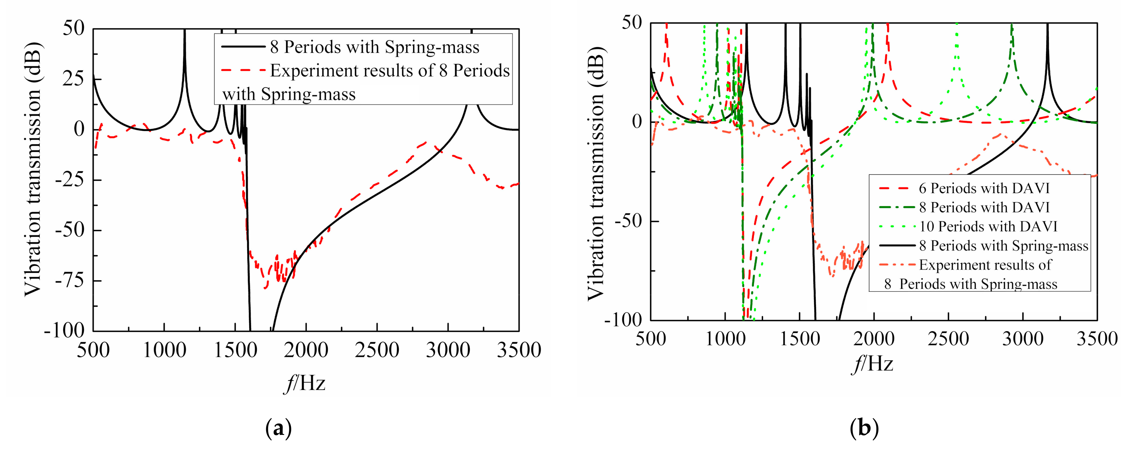
Secondly, the periodic structure with finite resonators was studied for comparison with the results given in [23]. Here, the periodic rods with six, eight, and ten resonators were selected for analysis using the method given in Section 2.2. The simulation parameters are the same as in Table 1, with the difference being that the number of the periodic resonators is finite. The vibration transmissibility of the rod with eight periods with spring-mass is shown in Figure 6a and the corresponding experiment results given in [23] are also shown in the same figure. The results obtained in Section 2.2 have a good agreement with the experiment results given in [23]. Therefore, the proposed method in this paper can be used for further analysis with confidence. Figure 6b illustrates the vibration transmission of the finite periodic system with six, eight, and ten unit cells, respectively, using the method outlined in Section 2.2, from which it can be concluded that for the finite periodic structure, the more unit cells there are, the greater the attenuation within the band gap.
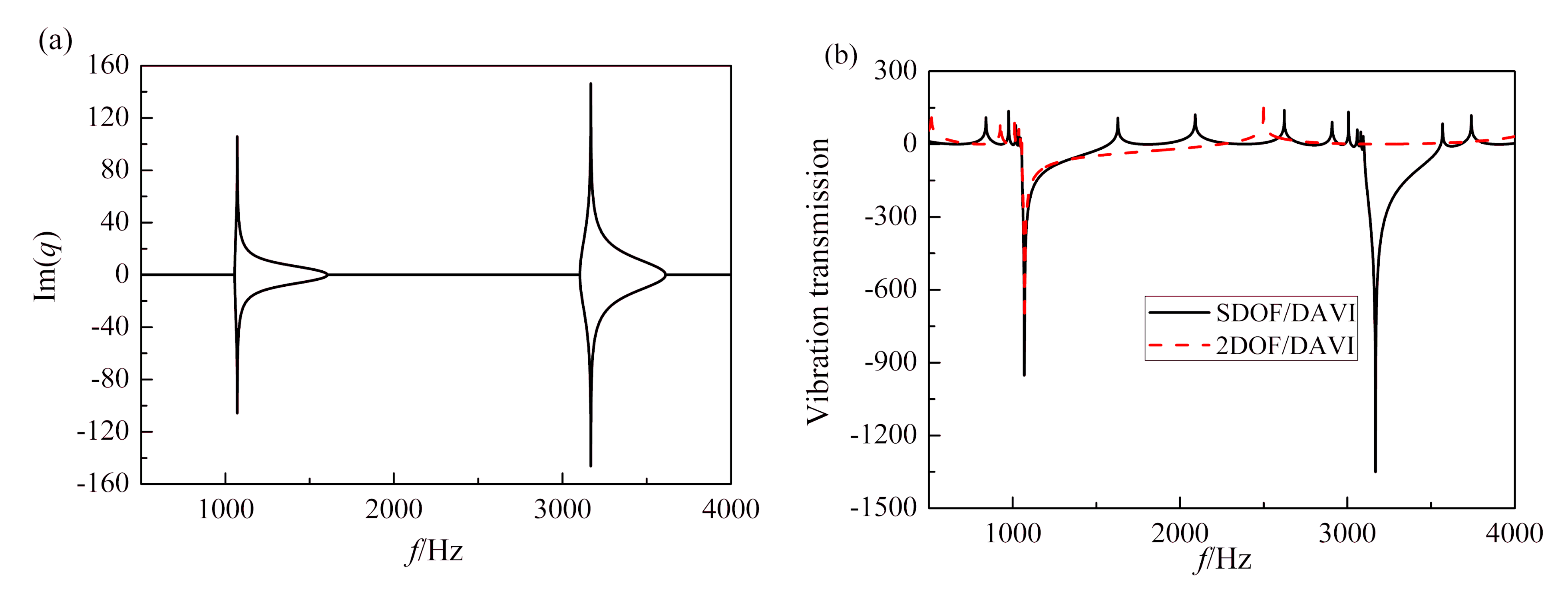
Finally, a periodic structure periodically attached with a two-degree-of-freedom (2DOF) DAVI will be discussed. The parameters are chosen to be the same or equivalent to the ones used in the first example, except that the resonators use a 2DOF DAVI instead of an SDOF DAVI (characterized by M , m 1 , m 2 , k1, and k2) with an equivalent total mass and stiffness (i.e., M + m 1 + m 2 = 0.0476   kg , k 1 k 2 ( k 1 + k 2 ) = 5.12 × 10 6   N / m ). The parameters of the 2DOF DAVI are chosen as m 1 = 0.01   kg , m 2 = 0.01   kg , M = 0.0276 kg, α1 = 3, α2 = 3, k1 = 6 × 10⁶ N/m, and k2 = 3.49 × 10⁷ N/m. According to these parameters, the 2DOF DAVI’s first and second resonance frequencies can be calculated as f1 = 1075 Hz and f2 = 3171 Hz, respectively.
Figure 7a shows the band gap characteristic of the periodic structure with 2DOF DAVI resonators of an infinite system. As envisaged, there are two locally resonant band gaps. The band gaps are 1056~1604 Hz and 3099~3612 Hz, respectively. Then, the periodic structure with ten unit cells is investigated. The parameters of the resonators are kept the same with the infinite system. The responses are also compared with the case of SDOF DAVI resonator attachments (with parameters equivalent to those of the 2DOF resonators and the resonance frequency being tuned to f1 = 1075 Hz). The results are also shown in Figure 7b. It can be concluded that 2DOF DAVI resonators outperform SDOF DAVI resonators in terms of achieving two band gaps with excellent attenuation performance at two specific frequencies. However, it should be noted that the band-gap width corresponding to the SDOF case is much broader.
According to the results given above, the initial frequency of the local resonance band gap is equal to the resonance frequency of the corresponding resonator. Due to the inertial amplification mechanism of the DAVI, using the same parameters, the DAVI has a lower resonance frequency than the spring mass system. Therefore, the periodic structure with the DAVI as the resonator can achieve a lower band gap than the traditional spring mass resonator without increasing the mass ratio of the system. This will make the structure proposed in this paper have the potential to be used in the low frequency vibration control field. For the structure with multi-degree-of-freedom (MDOF) resonators, its band gap number is equal to the freedoms of the resonator. However, the width of the band gap will become narrower compared with the SDOF condition.

3.2. Band Gap Formation Mechanisms

According to the first numerical results given in Section 3.1, the proposed periodic structure in this study mainly has two obvious differences compared with the one in [23]. One is that with the same parameters, the periodic structure proposed in this study has a lower locally resonant band gap; the other is that the width of the locally resonant band gap generated by the periodic structure with the DAVI is narrower.
According to the results, the largest attenuation within the locally resonant band gap occurs at the resonators’ resonance frequency. Therefore, the working mechanism of the resonator is similar to a dynamic vibration absorber (DVA). The location of the band gap can be tuned by changing the resonance frequency of the resonators.
The resonance frequency of the spring mass and DAVI are
ω spring = k m
ω DAVI = k M + m 1 α 2
From Equations (19) and (20), assuming that the two resonators have equivalent parameters, the stiffness of the two resonators are identical, and the masses of the resonators are equivalent ( m = M + m 1 ). Therefore, it is easy to obtain ω DAVI ω spring provided that the leverage ratio is large enough. Hence, the first difference is explained.
To explain the second distinction, the equivalent dynamic mass denoted by meffect and m effect for the DAVI resonator and spring mass resonator, respectively, is introduced.
For the DAVI resonators,
m effect = F 0 2 u ( 0 , t ) t 2 = { [ k + ω 2 m 1 α 1 ( 1 α 1 ) ] 2 k ω 2 ( M + m 1 α 1 2 ) k + ω 2 [ m 0 + m 1 ( 1 α 1 ) 2 ] } P n + e i ω t 1 ω 2 P n + e i ω t = { [ k + ω 2 m 1 α 1 ( 1 α 1 ) ] 2 k ω 2 ( M + m 1 α 1 2 ) k + ω 2 [ m 0 + m 1 ( 1 α 1 ) 2 ] } 1 ω 2
For the spring mass resonators,
m effect = F 2 u ( 0 , t ) t 2 = [ k ω 2 ( m + m 0 ) ω 4 m 0 m ] P n + e i ω t k ω 2 m 1 ω 2 P n + e i ω t = k ( m + m 0 ) ω 2 m 0 m k ω 2 m
where 2 u ( 0 , t ) t 2 is the acceleration at the same point.
Using the same parameters as in the first example, the equivalent dynamic mass versus frequency is shown in Figure 8. It can be seen that there is one peak and one tongue in the response of the DAVI; the same characteristics can be observed in the response of the spring mass resonator. It can be seen that the anti-resonant frequencies of the DAVI’s equivalent dynamic mass and spring mass’ equivalent dynamic mass are 1963 Hz and 3290 Hz, respectively, which is quite close to the cutoff frequencies given in the first numerical example. Therefore, it can be concluded that the cutoff frequency of the locally resonant band gap is related to the anti-resonant frequency of its equivalent dynamic mass. It can be also concluded that the wave attenuation degree in the band gap is related to the equivalent dynamic mass of the resonator, and the bigger the effective mass, the heavier the wave attenuation in the band gap.
From Figure 8, it can also be seen that as the effective mass between the resonance frequency and the anti-resonance frequency is monotonically reduced, so is the wave attenuation in the band gap. From Equation (23), the anti-resonant frequency of the DAVI’s equivalent dynamic mass can be obtained as
ω = k ( m 0 + m 1 + M ) m 0 ( M + m 1 α 1 2 ) + m 1 M ( 1 α 1 ) 2
From Equation (24), it can be seen that, due to the introduction of the lever, the DAVI’s equivalent dynamic mass will be smaller than that of the spring mass’, which can be obtained by letting m 1 = α 1 = 0 in Equation (24). Therefore, it can also be further concluded that the larger the lever ratio, the lower the cutoff frequency that will be obtained.

3.3. The Optimization Problem

The examples given in Section 2 are only with some specifically chosen system parameters for the periodic structures with SDOF and 2DOF DAVI resonators. In this section, the aim is to optimize the DAVI expecting the same resonators with the same equivalent parameters as the previous example, then using the optimized DAVI, a lower locally resonant band gap can be generated, for example within 1000 Hz.
Before presenting the optimization problem, some definitions need to be given first. In this system, the mass ratio is defined as μ = ( m 1 + m 2 + + m n ) / M . The parameters of the DAVI resonators are equivalent to the spring mass resonators proposed in [23]. The optimization problem for the n-degree-of-freedom DAVI can be given in Table 2. As mentioned before, the imaginary part of q denotes the wave attenuation and its amplitude indicates its attenuation performance. Thus, the sum of the imaginary part of q within 1000 Hz can be used as the objective function. By maximizing the objective function, the maximum attenuation band gap within the given frequency range can be obtained under the given parameters. As the number of the parameters of the MDOF DAVI resonator is larger than the spring mass resonator, in order to keep the parameters equivalent, the equality constraints have been imposed on it. The inequality constraints g1 and g2 are used to guarantee that the isolator can be realized and that the size of the isolator is not too large.
This problem has 2n + 1 variables and two equality constraints. The solution space has a dimension of 2n − 1.
In order to obtain some quantitative results, the cases for n = 2 will be given in this study. The number of the variables in the optimization problem is five, which are M, m 1 , m 2 , k1, and k2. There are two equality constraints and five variables. The variables M, m 2 , and k2 are defined as the state variables and satisfy the equality constraints. The remaining two variables, m 1 and k1, are named the decision variables. Using equality constraints h1 and h2, the state variables M, m 2 , and k2 may be easily solved in terms of the choice variables. The constraints imposed on the lever ratio αi are given by the inequality constraint g1. To determine the decision variables that maximize the attenuation constant f, in this study, the MIGA is used to meet the equality constraints and the inequality constraints g1 and g2.
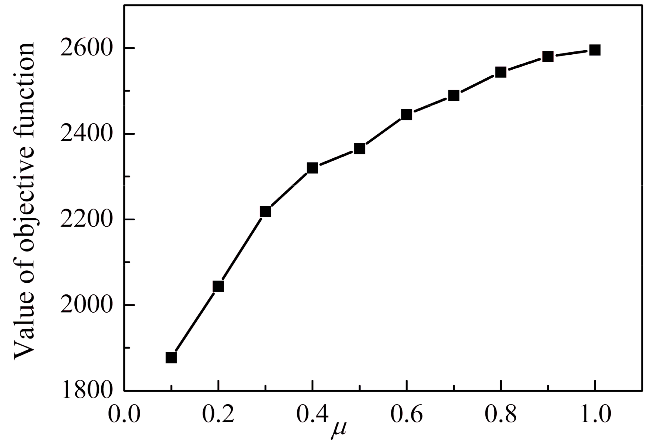
During the optimization process, the mass ratio changes from 0.1 to 1, and the increment is 0.1. Figure 9 shows the attenuation constant versus the mass ratio μ. Generally speaking, with the increase of the μ, the value of the objective function increases gradually. Therefore, in this section, only the complex band structure for μ = 1 is given.
During the process of optimization, the constraints imposed on the 2DOF of the DAVI are shown in Table 3. The optimal parameter sets for the 2DOF of DAVI are given in Table 4.
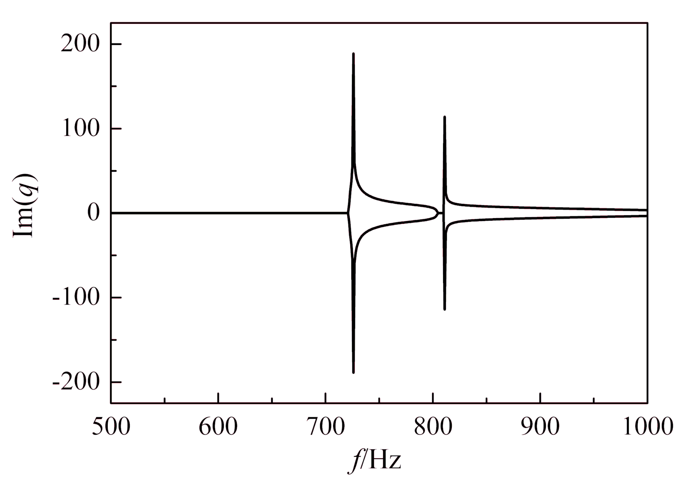
Figure 10 shows the objective function versus the generations. It can be seen that the objective function is converged. Figure 11 gives the band gap characteristics of the locally resonant band gap for μ = 1. It can be seen that there are two locally resonant band gaps within 1000 Hz, respectively. The comparisons of locally resonant band gaps before and after the optimization are shown in Table 5. It can be concluded that after optimization, the frequency ranges of the two band gaps are from 720 Hz to 804 Hz and 809 Hz to 1000 Hz, respectively, which are substantially lower than the values of the second instance obtained in Section 3.1. The initial frequencies are decreased by 32% and 74%, respectively. Although the width of the band gap becomes much narrower compared with the second example given in Section 3.1, this band width is usually enough in the field of the vibration isolation.

4. Conclusions

In this paper, the longitudinal elastic wave propagation and vibration transmission in one-dimensional LR metamaterial-based rod systems containing SDOF and MDOF DAVI resonators were investigated, respectively. Due to the inertial amplification mechanism, the SDOF DAVI resonators can generate a lower resonance frequency than the SDOF spring mass system. Therefore, the band gap of the infinite periodic structure with the SDOF DAVIs as resonators is lower than the structure with the SDOF spring mass resonators. The numerical results were validated by comparing them with those of the published study. The vibration transmissibility of the finite periodic structure with several periodic resonators was also studied. The results show that the more unit cells there are, the greater the attenuation within the band gap. According to the research, multiple band gaps can be achieved in metamaterial-based rods including MDOF resonators. It was found that the attenuation ability in the band gap is related to the defined effective dynamic mass: the larger the effective dynamic mass, the greater the attenuation that will be obtained and vice versa.
In order to investigate the lowest initial band frequency of the periodic structure with 2DOF DAVI resonators under the given equivalent parameters, the MIGA method was used to optimize the parameters. With the optimal 2DOF DAVI resonators periodically arrayed on the elastic rod, the initial frequency of the first locally resonant band gap and the second locally resonant band gap can be decreased by 32% and 74%, respectively. In the near future, we are going to investigate the vibration transmissibility of the periodically layered isolators with DAVIs as resonators. The expectation is that the combined structure will be applied to isolate the longitudinal vibration of the propeller-shafting system. The findings reported in this research will aid in the development of a DAVI-based metamaterial-based rod to be used in low-frequency vibration control.

Author Contributions

Conceptualization, N.L.; methodology N.L. and F.L.; formal analysis, N.L.; investigation, N.L. and X.L.; data curation, N.L. and X.X.; writing—original draft preparation, N.L.; writing—review and editing, F.L.; supervision, N.L.; project administration, N.L. All authors have read and agreed to the published version of the manuscript.

Funding

This research is supported in part by the Education and Scientific Research Foundation for Young Teachers in Fujian Province under Grant JAT190009; in part by the State Key Discipline Laboratory of Noise and Vibration Control of Ship Equipment in Shanghai Jiaotong University under Grant VSN202103; in part by the National Natural Science Foundation of China under Grant 52105091; and in part by Starting Grants of Fuzhou University under Grant GXRC-20014 and Grant GXRC-20018, and Fujian Provincial Natural Science Foundation 2021J05115.

Institutional Review Board Statement

Not applicable.

Informed Consent Statement

Not applicable.

Data Availability Statement

The data presented in this study are available within the article.

Conflicts of Interest

The authors declare no conflict of interest.

Nomenclature

aSpacing of resonators
ACross-section area of the rod
cSpeed of the elastic wave in the matrix material
EYoung’s modulus of the rod
F0Reaction force at attachment point between resonator and periodic structure
FiExternal force acting on the i-th stage
FForce vector
iIndex
IImaginary unit
kStiffness of a single degree-of-freedom dynamic anti-resonant vibration isolator
kiStiffness of i-th spring of the i-th isolator
KStiffness matrix
l1Lever length of the lever in the case of a single-degree-of-freedom lever type anti-resonant vibration isolator
l2Distance between two pivot points in the case of a single-degree-of-freedom lever type anti-resonant vibration isolator
m0Lumped mass at attachment point between resonator and periodic structure
misIsolator mass
m 1 ith isolator mass of the multi-degree-of-freedom resonator
MLoad mass
MMass matrix
P i Integral constant of the i-th rod
P i + Integral constant of the i-th rod
q0Displacement at the attachment point
qWave vector
qDisplacement vector
qiDisplacement of the i-th isolator stage
S0Dynamic stiffness of resonator at the attachment point between the resonator and the rod
tTime
TDisplacement transmissibility
u(x,t)Longitudinal displacement at position x and time t
xGlobal coordinate
αLever ratio of a single-degree-of freedom lever-type anti-resonant vibration isolator
αiLever ratio of the i-th isolator stage in a multi-degree-of-freedom lever type anti-resonant vibration isolator
βWave number
ρDensity of the rod
ωCircular frequency

References

  1. Sigalas, M.; Kushwaha, M.S.; Economou, E.N.; Kafesaki, M.; Psarobas, I.E.; Steurer, W. Classical vibrational modes in phononic lattices: Theory and experiment. Zeitschrift für Kristallographie-Cryst. Mater. 2005, 220, 765–809. [Google Scholar] [CrossRef]
  2. Xiao, Y.; Mace, B.R.; Wen, J.; Wen, X. Formation and coupling of band gaps in a locally resonant elastic system comprising a string with attached resonators. Phys. Lett. A 2011, 375, 1485–1491. [Google Scholar] [CrossRef]
  3. Kushwaha, M.S.; Halevi, P.; Dobrzynski, L.; Djafari-Rouhani, B. Acoustic band structure of periodic elastic composites. Phys. Rev. Lett. 1993, 71, 2022. [Google Scholar] [CrossRef]
  4. Yadav, A.; Gerislioglu, B.; Ahmadivand, A.; Kaushik, A.; Cheng, G.J.; Ouyang, Z.; Wang, Q.; Yadav, V.S.; Mishra, Y.K.; Wu, Y.; et al. Controlled self-assembly of plasmon-based photonic nanocrystals for high performance photonic technologies. Nano Today 2021, 37, 101072. [Google Scholar] [CrossRef]
  5. Yu, D.; Liu, Y.; Wang, G.; Cai, L.; Qiu, J. Low frequency torsional vibration gaps in the shaft with locally resonant structures. Phys. Lett. A 2006, 348, 410–415. [Google Scholar] [CrossRef]
  6. Liu, Z.; Zhang, X.; Mao, Y.; Zhu, Y.Y.; Yang, Z.; Chan, C.T.; Sheng, P. Locally resonant sonic materials. Science 2000, 289, 1734–1736. [Google Scholar] [CrossRef]
  7. Oudich, M.; Li, Y.; Assouar, B.M.; Hou, Z. A sonic band gap based on the locally resonant phononic plates with stubs. New J. Phys. 2010, 12, 083049. [Google Scholar] [CrossRef]
  8. Goffaux, C.; Sánchez-Dehesa, J.; Yeyati, A.L.; Lambin, P.; Khelif, A.; Vasseur, J.O.; Djafari-Rouhani, B. Evidence of fano-like interference phenomena in locally resonant materials. Phys. Rev. Lett. 2002, 88, 225502. [Google Scholar] [CrossRef] [Green Version]
  9. Liu, Z.; Chan, C.T.; Sheng, P. Three-component elastic wave band-gap material. Phys. Rev. B 2002, 65, 165116. [Google Scholar] [CrossRef] [Green Version]
  10. Wang, G.; Wen, X.; Wen, J.; Shao, L.; Liu, Y. Two-dimensional locally resonant phononic crystals with binary structures. Phys. Rev. Lett. 2004, 93, 154302. [Google Scholar] [CrossRef]
  11. Wang, G.; Wen, J.; Wen, X. Quasi-one-dimensional phononic crystals studied using the improved lumped-mass method: Application to locally resonant beams with flexural wave band gap. Phys. Rev. B 2005, 71, 104302. [Google Scholar] [CrossRef]
  12. Hsu, J.C.; Wu, T.T. Lamb waves in binary locally resonant phononic plates with two-dimensional lattices. Appl. Phys. Lett. 2007, 90, 201904. [Google Scholar] [CrossRef] [Green Version]
  13. Yang, Z.; Dai, H.M.; Chan, N.H.; Ma, G.C.; Sheng, P. Acoustic metamaterial panels for sound attenuation in the 50–1000 Hz regime. Appl. Phys. Lett. 2010, 96, 041906. [Google Scholar] [CrossRef]
  14. Li, J.; Chan, C.T. Double-negative acoustic metamaterial. Phys. Rev. E 2004, 70, 055602. [Google Scholar] [CrossRef] [PubMed] [Green Version]
  15. Fang, N.; Xi, D.; Xu, J.; Ambati, M.; Srituravanich, W.; Sun, C.; Zhang, X. Ultrasonic metamaterials with negative modulus. Nat. Mater. 2006, 5, 452–456. [Google Scholar] [CrossRef]
  16. Ciaburro, G.; Iannace, G. Modeling acoustic metamaterials based on reused buttons using data fitting with neural network. J. Acoust. Soc. Am. 2021, 150, 51–63. [Google Scholar] [CrossRef]
  17. Ciaburro, G.; Iannace, G. Membrane-type acoustic metamaterial using cork sheets and attached masses based on reused materials. Appl. Acoust. 2022, 189, 108605. [Google Scholar] [CrossRef]
  18. Milton, G.W.; Briane, M.; Willis, J.R. On cloaking for elasticity and physical equations with a transformation invariant form. New J. Phys. 2006, 8, 248. [Google Scholar] [CrossRef]
  19. Sukhovich, A.; Jing, L.; Page, J.H. Negative refraction and focusing of ultrasound in two-dimensional phononic crystals. Phys. Rev. B 2008, 77, 014301. [Google Scholar] [CrossRef]
  20. Norris, A.N. Acoustic cloaking theory. Proc. R. Soc. Lond. A Math. Phys. Eng. Sci. 2008, 464, 2411–2434. [Google Scholar] [CrossRef]
  21. Torrent, D.; Sánchez-Dehesa, J. Acoustic cloaking in two dimensions: A feasible approach. New J. Phys. 2008, 10, 063015. [Google Scholar] [CrossRef] [Green Version]
  22. Zhang, S.; Xia, C.; Fang, N. Broadband acoustic cloak for ultrasound waves. Phys. Rev. Lett. 2011, 106, 024301. [Google Scholar] [CrossRef] [PubMed]
  23. Wang, G.; Wen, X.; Wen, J.; Liu, Y. Quasi-one-dimensional periodic structure with locally resonant band gap. J. Appl. Mech. 2006, 73, 167–170. [Google Scholar] [CrossRef]
  24. Xiao, Y.; Wen, J.; Wen, X. Longitudinal wave band gaps in metamaterial-based elastic rods containing multi-degree-of-freedom resonators. New J. Phys. 2012, 14, 033042. [Google Scholar] [CrossRef]
  25. Song, Y.; Wen, J.; Yu, D.; Liu, Y.; Wen, X. Reduction of vibration and noise radiation of an underwater vehicle due to propeller forces using periodically layered isolators. J. Sound Vib. 2014, 333, 3031–3043. [Google Scholar] [CrossRef]
  26. Zhou, J.; Wang, K.; Xu, D.; Ouyang, H. Multi-low-frequency flexural wave attenuation in Euler–Bernoulli beams using local resonators containing negative-stiffness mechanisms. Phys. Lett. A 2017, 381, 3141–3148. [Google Scholar] [CrossRef]
  27. Zhou, J.; Dou, L.; Wang, K.; Xu, D.; Ouyang, H. A nonlinear resonator with inertial amplification for very low-frequency flexural wave attenuations in beams. Nonlinear Dyn. 2019, 96, 647–665. [Google Scholar] [CrossRef]
  28. Wang, K.; Zhou, J.; Xu, D.; Ouyang, H. Lower band gaps of longitudinal wave in a one-dimensional periodic rod by exploiting geometrical nonlinearity. Mech. Syst. Signal Process. 2019, 124, 664–678. [Google Scholar] [CrossRef]
  29. Cai, C.; Zhou, J.; Wu, L.; Wang, K.; Xu, D.; Ouyang, H. Design and numerical validation of quasi-zero-stiffness metamaterials for very low-frequency band gaps. Compos. Struct. 2020, 236, 111862. [Google Scholar] [CrossRef]
  30. Wang, K.; Zhou, J.; Ouyang, H.; Cheng, L.; Xu, D. A semi-active metamaterial beam with electromagnetic quasi-zero-stiffness resonators for ultralow-frequency band gap tuning. Int. J. Mech. Sci. 2020, 176, 105548. [Google Scholar] [CrossRef]
  31. Flannelly, W.G. Dynamic Antiresonant Vibration Isolator. U.S. Patent 3,322,379, 30 May 1967. [Google Scholar]
  32. Liu, N.; Li, C.; Yin, C.; Dong, X.; Hua, H. Application of a dynamic antiresonant vibration isolator to minimize the vibration transmission in underwater vehicles. J. Vib. Control 2018, 24, 3819–3829. [Google Scholar] [CrossRef]
  33. Wells, D.A. Theory and Problems of Lagrangian Dynamics; Schaum-Publishing: Mequon, WI, USA, 1967. [Google Scholar]
  34. Rao, S.S. Vibration of Continuous Systems; John Wiley & Sons: Hoboken, NJ, USA, 2019. [Google Scholar]
  35. Mead, D.J. A general theory of harmonic wave propagation in linear periodic systems with multiple coupling. J. Sound Vib. 1973, 27, 235–260. [Google Scholar] [CrossRef]
  36. Downing, C.A.; Saroka, V.A. Exceptional points in oligomer chains. Commun. Phys. 2021, 4, 254. [Google Scholar] [CrossRef]
Figure 1. Simplified schematic diagram of dynamic anti-resonance vibration isolator: x is the displacement of the load mass, z is the displacement of the isolator mass, k is the mount stiffness, M is the mass of the load, mis is the isolator mass, l1 is the length of the lever, and l2 is the distance between two pivot points, α = l 2 / l 1 .
Symmetry 14 01030 g001
Figure 2. Sketch of an infinite metamaterial-based uniform rod with a periodic array of (MDOF) DAVI resonators.
Symmetry 14 01030 g002
Figure 3. The amplification schematic diagram of an MDOF DAVI resonator with its main displacement symbol.
Symmetry 14 01030 g003
Figure 4. Simplified schematic diagram of a finite periodic structure with n unit cells under longitudinal excitation and the longitudinal wave of the structure is indicated by w.
Symmetry 14 01030 g004
Figure 5. Complex band structure of an infinite metamaterial-based rod with a periodic array of SDOF spring mass or DAVI as resonator: (a) real (q) and (b) Im (q), the green dot line represents those results obtained in [23].
Symmetry 14 01030 g005
Figure 6. Vibration transmission characteristic of a finite periodic structure: (a) measured (experiment result denoted by red dash line is refer to [23]) and calculated vibration transmission for eight unit cells of a periodic system and (b) vibration transmission of period systems with different unit cells.
Symmetry 14 01030 g006
Figure 7. Band gap characteristic of metamaterial-based rod with a periodic array of 2DOF DAV resonators: (a) infinite periodic system and (b) vibration transmittance of finite periodic structure with ten unit 2DAVI resonators and SDOF resonators.
Symmetry 14 01030 g007
Figure 8. Dependence of the equivalent dynamic mass to frequency: the black dotted line denotes the SDOF DAVI resonator and the red solid line denotes the spring mass resonator.
Symmetry 14 01030 g008
Figure 9. Sum of the imaginary part of the infinite periodic structure with the mass ratio μ.
Symmetry 14 01030 g009
Figure 10. The sum of the imaginary part of the complex number versus the number of the MIGA generations.
Symmetry 14 01030 g010
Figure 11. Band gap characteristics of metamaterial-based rods periodically attached with 2DOF DAVI with   α 1 = 5.2 , α 2 = 11.4 , k 1 = 3.4 × 10 7   N / m , k 2 = 6.1 × 10 6   N / m , m1 = 0.00719 kg, and m2 = 0.0166 kg.
Symmetry 14 01030 g011
Table 1. Parameters of the periodic structure.
Parameter SymbolValue
Parameters of the rodA (m2) 5 × 10 5
E (Pa) 1.5 × 10 10
ρ (kg/m3) 1200
The spacing of the resonatorsa (m)0.05
Parameters of the spring-mass resonatork (N/m) 5.12 × 10 6
m (kg)0.0476
m0 (kg)0.016
Table 2. Description of the optimization problem.
Object Functionf = ∑ lm (q)Maximize
Subject to h 1 : i = 1 n m i = μ M for i = 1,2, n .
h 2 : i = 1 n 1 k i = 1 k
g 1 : 2 α i 40
g 2 : 0 m i ,   k k i
Table 3. Optimization limits for the 2DOF DAVI.
DAVI ParameterLower LimitUpper Limit
α 1 240
α 2 240
k1 (N/m)5.12 × 1065 × 107
m1 (kg)0.0010.0238
Table 4. Optimal parameters for 2DOF DAVI.
DAVI ParameterOptimized
α 1 5.2
α 2 11.4
k1 (N/m)3.4 × 107
k2 (N/m)6.1 × 106
m1 (kg)0.00719
m2 (kg)0.0166
Table 5. Bandwidth comparison.
Resonance GapFirst Locally Resonant Band GapSecond Locally Resonant Band Gap
Optimization1063~1603 Hz3103~3611 Hz
Optimal720~804 Hz809~1000 Hz
Percentages of decline32%74%
Publisher’s Note: MDPI stays neutral with regard to jurisdictional claims in published maps and institutional affiliations.