Article

T-Stress Evaluation Based Cracking of Pipes Using an Extended Isogeometric Analysis (X-IGA)

by
Khadija Yakoubi
1,
Soufiane Montassir
1,
Hassane Moustabchir
2,*,
Ahmed Elkhalfi
1,
Maria Luminita Scutaru
3,* and
Sorin Vlase
3,4,*
1
Faculty of Science and Technology, Sidi Mohamed Ben Abdellah University, Fez 30000, Morocco
2
Laboratory of Systems Engineering and Applications (LISA), National School of Applied Sciences of Fez, Sidi Mohamed Ben Abdellah University, Fez 30000, Morocco
3
Department of Mechanical Engineering, Transilvania University of Brasov, B-dul Eroilor 20, 500036 Brasov, Romania
4
Romanian Academy of Technical Sciences, B-dul Dacia 26, 030167 Bucharest, Romania
*
Authors to whom correspondence should be addressed.
Symmetry 2022, 14(5), 1065; https://doi.org/10.3390/sym14051065
Submission received: 3 April 2022 / Revised: 11 May 2022 / Accepted: 17 May 2022 / Published: 23 May 2022
(This article belongs to the Section Mathematics)

Abstract

:
The aim of this study is to investigate the problem of pipe cracking based on T-stress analysis and the influence of other parameters, using a numerical computation performed by extended isogeometric analysis (X-IGA). This article examines the T-stress, which defines the second term of the Williams’ series expansion. T-stress provides effective elastic modeling at the crack tip. Using the extended iso-geometric analysis (X-IGA), we determined the distribution of T-stress at the crack tip in a pipe under internal pressure as a function of internal pressure, crack size, and Poisson’s ratio. To validate the promising findings, the results are expanded with a comparison to the extended finite element (X-FEM) method and existing research in this field, and we obtained an error between 0.2% and 4.6%. This work demonstrated the significance of T-stress in fracture description, the effect of Poisson’s ratio and size on T-stress, and that X-IGA provided accurate numerical results by precisely describing the geometry of the crack and enriching it.

1. Introduction

Gas pipelines are critical and complex constructions, and their failure might lead to disaster. The majority of the damage is due to defects, leakage, and cracks, which change the failure model of material and structures. To assess the safety of engineering gas structures, the accurate prediction of crack tip fracture parameters such as stress intensity factors (SIFs), T-stress, and the higher-order terms in the Williams’ series expansion is a crucial point in fracture analysis.
T-stress is described in this study as a cracking problem in an arc that is under internal pressure. T-stress is the transverse constraint; it activates parallel to the propagation and the lips of the crack and is frequently negligible, although various works have demonstrated its importance [1,2,3]. Cotterell [4] demonstrated that the first term of the Williams expansion, stress intensity factor (SIF), affects the start of the crack, while the second term, T-stress, regulates the stability of the crack direction (Figure 1).
Meliani [5] demonstrated experimentally and numerically the necessity to enhance the factor of stress intensity with a second component, T-stress. T-stress has an influence on the plastic zone, causing it to extend and alter form as the absolute amount of T-stress increases [6]. When it comes to the stability of the fracture propagation direction, the T-stress is quite important. As a result, a negative T-stress indicates a stable direction, whereas a positive T-stress indicates an unstable direction [7]. Shahani et al. [2] demonstrated the influence of T-stress on the crack propagation angle using the MTS parameter; the principle of the method is that the crack propagates in the direction of maximum tangential stress. In addition, Miao et al. [8] demonstrated the importance of T-stress on crack initiation and plasticity at the crack’s bottom by assessing three specimens, including a central cracked plate (CCP), a compact tension specimen (CTS), and a four-point bending specimen (FPB), using the 3D FE approach. In two-dimensional (2D) quasicrystals, Ya-RuSuo et al. [9] studied the T-stress towards the extremities of an unequal-arm cruciform crack. Additionally, T-stress has a significant impact on crack propagation of brittle fractures in mode II fractures [10]. Other researchers showed that negative T-stress enhances apparent fracture toughness whereas positive T-stress decreases it [7,8]. Y. G. Matvienko [11] investigated the influence of stress parameters near the crack tip, especially T-stress, on several elastic and elastic–plastic fracture mechanics issues. Ayattolahi’s studies also provide essential information on the significance of T-stress [10,11,12,13,14,15].
Accurately measuring the stress at the crack tip allows for more precise fracture parameters K-T, which is why we used extended isogeometric analysis (X-IGA). IGA is a method for integrating finite element analysis (FEA) with typical NURBS-based CAD design tools [16]; it is an approach for describing geometry and analysis on the same basis. Hughes et al. [17] were the first to suggest using NURBS as basis functions in analysis. For the simulation of massive elasto-plastic deformation in 3D solid structures, Lai et al. [18] employed IGA based on Bézier extraction of NURBS. The Bézier extraction operation is based on the decomposition of NURBS basis functions into a set of Bézier elements of continuity C0 and a set of Bernstein polynomials in a linear combination.
To model the discontinuities, the IGA was combined with X-FEM, using X-FEM for presenting the fracture by enrichment functions and IGA for modeling the geometry. Several studies have demonstrated the precision of X-IGA when compared to the traditional finite element (FEM) approach and X-FEM [19,20]. The X-IGA technique has been employed in a variety of disciplines, including vibration analysis [21], composites [22,23], and the optimization of structural design [24]. Additionally, for cracking issues, X-IGA has shown satisfactory results; Kapoor et al. [25], Wang et al. [26], Yadav et al. [27] used the X-IGA method to investigate the dynamic fracture behavior of stationary fractures in isotropic/orthotropic media under impact loading. Nguyen-Thanh et al. [28] proposed the X-IGA formula for crack evaluation of thin shell cracks which were through-thickness. Hou et al. [29] suggested a novel X-IGA approach for bi-material weak discontinuous issues based on B++ splines (Boundary plus plus splines). To model fracture problems, in [30,31,32] the authors employed the Bézier extraction-based T-spline XIGA (BEBT-XIGA). Fakkoussi et al. [19] proposed a new approach for detecting fracture behavior in pipeline constructions using the extended iso-geometric analysis (X-IGA) approach for a two-dimensional problem. Subroutines (UEL) were used to represent the X-IGA in Abaqus/Standard software. To simulate a two-dimensional crack in a pipe subjected to a uniform pressure, Montassir et al. [20] implemented the extended iso-geometric analysis (X-IGA) using MATLAB code.
The numerical approach X-IGA is used in this research to examine the problem of pipe cracking based on the analysis of T-stress and its influence on other parameters: crack length, Poisson’s ratio, and internal pressure. The novel aspect of this work is the investigation of T-stress in the vicinity of an internal crack in a pipe using extended isogeometric analysis.
The paper is structured in the following sections; Section 2 describes the extended isogeometric analysis, and the stress different method (SDM) to compute T-stress. Section 3 describes the studied geometry used, mesh, boundary conditions, and the numerical results obtained. The results are discussed in Section 4, and the conclusion is in the last section.

2. Theoretical Background

2.1. Extended Isogeometric Analysis

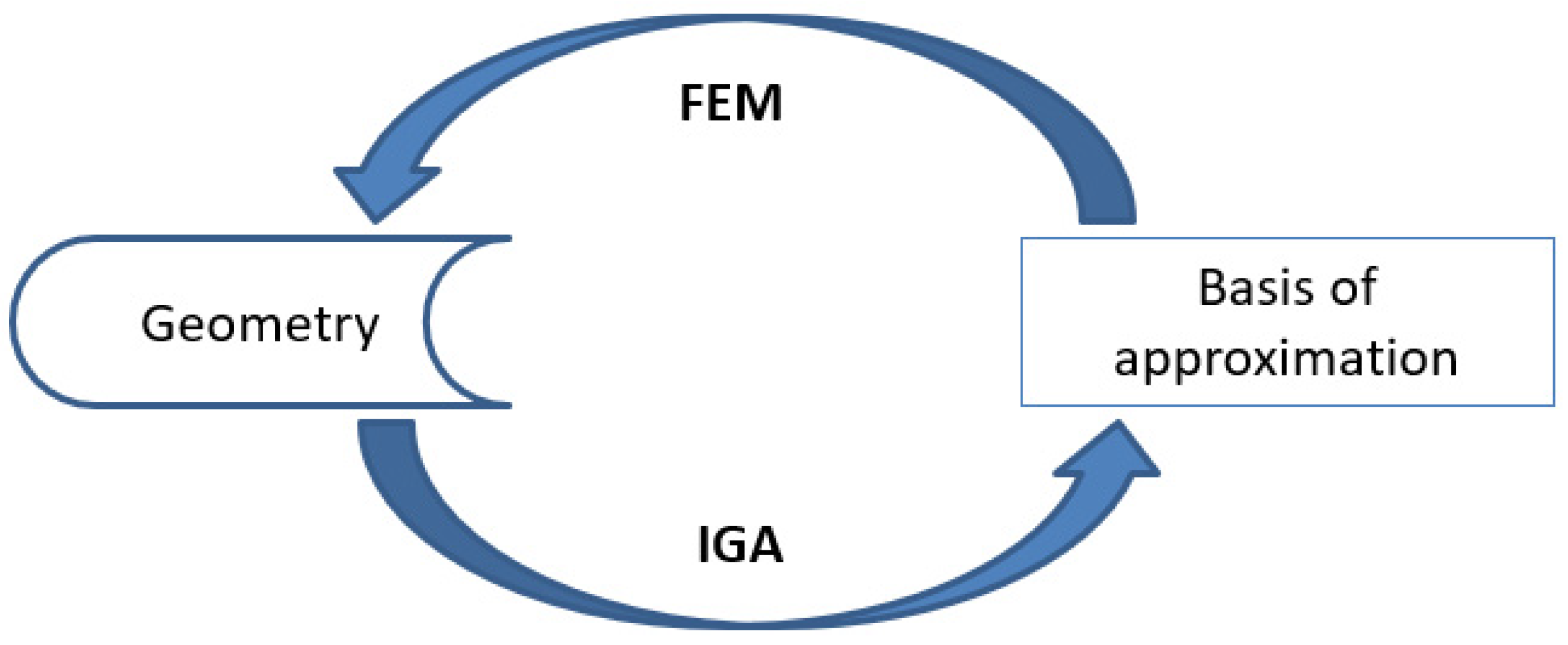
The isogeometric analysis uses non-uniform rational B-splines (NURBS) not only as a geometry discretization technology but also as a discretization tool for the analysis. The IGA is capable of producing accurate results with large meshes, whereas the finite element method (FEM) necessitates refinement. Ghorashi et al. [31] demonstrated that in order to have an error less than 0.1 for both numerical approaches, X-FEM and X-IGA, they needed to employ 25,000 elements for X-FEM and only 4300 for X-IGA, as well as a computation time twice as long for X-IGA. In the IGA, the basis for describing the exact geometry is used as a basis for approximating the solution (Figure 2).
Extended iso-geometric analysis (X-IGA) is a combination of the extended finite element technique X-FEM and the IGA, with the IGA presenting the accurate geometry and the X-FEM modeling the crack through enrichment [16].
u ( ξ ) = i n R i ( ξ ) u i + j n c f R j ( ξ ) [ H ( ξ ) H ( ξ j ) ] a j + k n c t R k ( ξ ) α = 1 4 [ ψ α ( ξ ) ψ α ( ξ ) ] b α k ,
where:
Ri is the basis function, a j and b α k are the standard and the further DOFs, respectively.
R i p ( ξ ) = N i , p ( ξ ) w i i = 1 n N i , p ( ξ ) w i ,
and w i : is the weight.
For p = 0
N i , 0 = { 1   ξ i   ξ < ξ i + 1 0                     o t h e r w i s e } ,
For p = 1, 2, …
N i , p ( ξ ) = ξ ξ i ξ i + p ξ i N i , p 1 + ξ i + p + 1 ξ ξ i + p + 1 ξ i + 1 N ( ξ ) i + 1 , p 1 ,
where ξ i R is the ith knot, i = 1 , 2 , . ,   n + p + 1 , p is the polynomial order, and n is the number of basic functions; it is a set of increasing reals defined in the parameter space called knot vector:
Ξ = { ξ 1 , ξ 2 , , ξ n + p + 1 } ,     ξ i < ξ i + 1 ,
The basis N i , p ( ξ ) functions are characterized by:
  • Partition of unity: i = 1 n N i , p ( ξ ) = 1 , signifying that the connection between the curve and its defining control points stays unchanged when subjected to affine transformation;
  • Positivity: ξ ,   N i , p ( ξ ) 0 The basis functions are non-negative;
  • Multiplicity: if internal knots are repeated m times, NURBS produces continuity of C p m ;
  • Linear independence: i = 1 n α i N i , p ( ξ ) = 0     α i = 0 .
We used the level set method (LSM) for enrichment; it allowed us to determine the position of the crack in order to enrich the crack’s lips and tips with the necessary function Figure 3:
H: is the Heaviside function, used to enrich the crack lips.
H ( ξ ) = { + 1       φ ( ξ ) > 0 0           φ ( ξ ) = 0 1       φ ( ξ ) < 0 }
ψ α : The functions of enrichments in the crack tip.

2.2. Computation of T-Stress

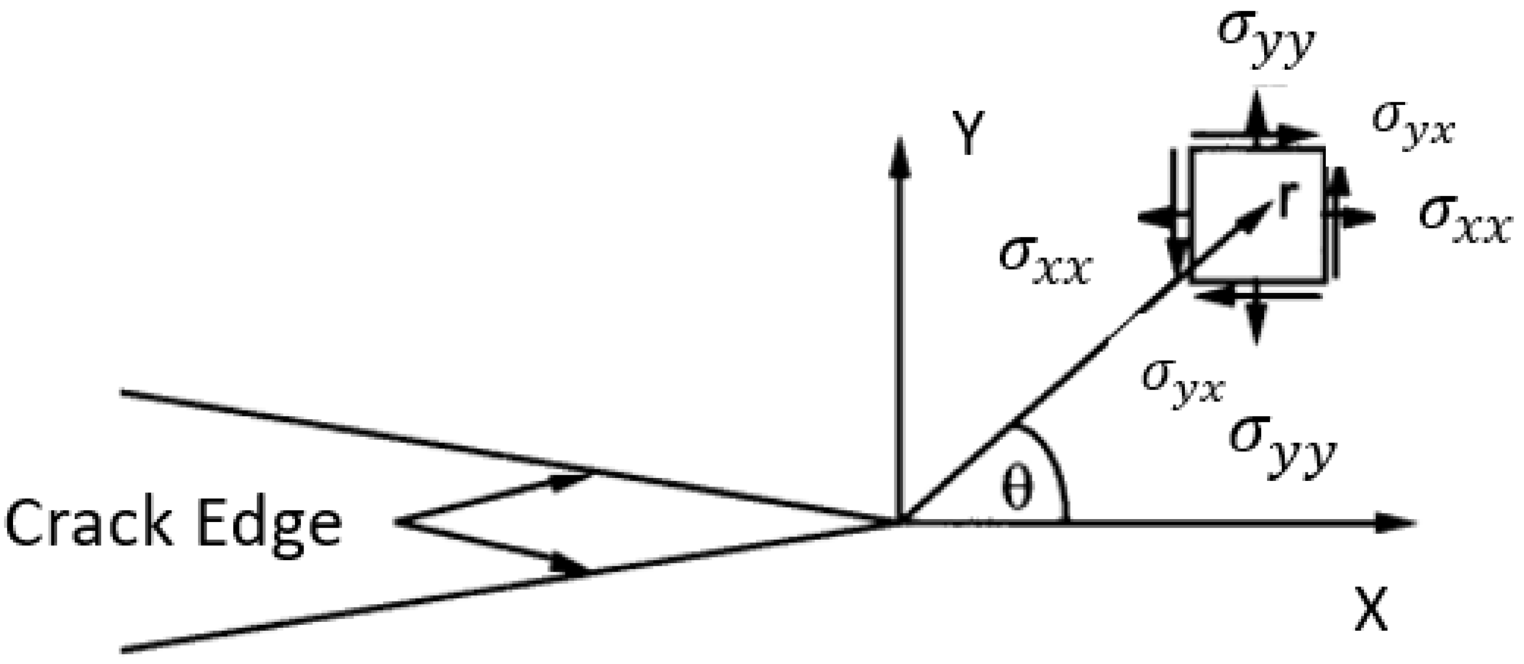
T-stress was computed using a variety of approaches [15,33], including the stress different method (SDM) as proposed by Yang [34]. The idea of this method is that the errors in the numerical values of σ 11 and σ 22 near a crack point progress with r in the same way, and the variation must effectively eliminate errors (Figure 4). The stress T is calculated for a homogeneous material using the difference in stresses in the principal directions along the ligament and for θ = 0 .
T = ( σ 11 σ 22 ) r = 0 , θ = 0
Maleski et al. [1] proposed the extrapolation approach, which employs the same principles as SDM.
T = ( σ x x σ y y ) = T 0 + γ ( x a )
Equation (7) is a linear relationship between T and the distance x to the crack tip, depending on γ . We can derive a value of T at x = 0 at the crack tip by extrapolating T as a function of x, denoted T0.
Kfouri [4] devised the Esheby integral approach for calculating the T-stress, which exploits the properties of the path-independent J-integral. The weight function method has demonstrated its effectiveness in a variety of cracking-related problems, including edge-cracked rectangular plates and circular disks [1].
Chao et al. [14] computed the error on the first component σ x x of the William’s series expansion numerically using finite elements by visualizing its distribution along the ligament for θ = 180 ° . The authors discovered an area with a consistent distribution. The measured value in the area is taken as the value of the T-stress.
Other widely used methods for estimating T-stress include the weakly singular symmetric Galerkin BEM (SGBEM) [35,36], the extended element-free Galerkin (EFG) method combined with M-integral [37], the finite block method (FBM) combined with J-integral [38], the meshless finite volume (MFV) method [39], FEM combined with M-integral [40], and BEM combined with M-integral [41].

3. Results

The study was performed on an arc with an internal crack; the type of crack is sharp, as illustrated in Figure 5. Table 1, Table 2 and Table 3 detail the attributes of the materials utilized (steel P264GH) and the behavior of the crack with the material is elastic. The input parameters, which include geometrical and material properties, are the first step in the computation technique in MATLAB software for the implementation of the X-IGA. The polynomial order p = 3, control points, and node vectors are used to construct the NURBS model; the number of elements is 480, and the number of control points is 2093. Secondly, we introduce the crack data, length (the crack length is between 3 and 6 mm), and coordinates of the crack points; we used the level set method to determine the crack position and select the enrichment points. The nodes are subjected to the Heaviside and crack tip functions. Then, the boundary conditions, nodal force vector, and stiffness matrix are computed. This method produces stress, strain, and displacement values, and computes T-stress by the stress different method (SDM).
The purpose of this article is to investigate T-stress in the context of pipe cracking. For this reason, we estimated T-stress as a function of internal pressure, crack size, and Poisson’s ratio using X-IGA and X-FEM. The stress fields were estimated using X-IGA in MATLAB and X-FEM in Abaqus.
We used six-node quadratic triangles in the region of the crack tip and eight-node quadratic plane stress quadrilaterals across the geometry to mesh the X-FEM, with 27,640 elements (Figure 5).
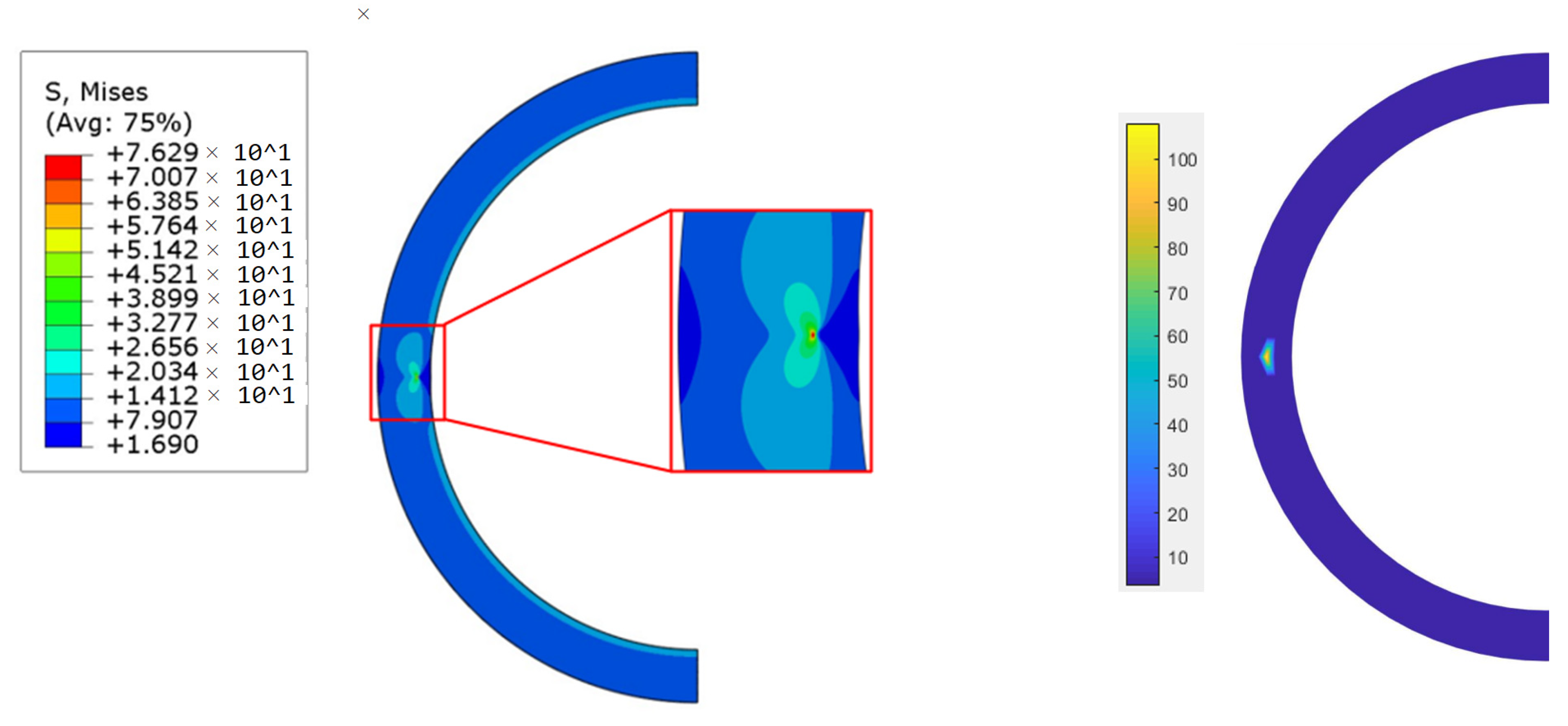
Figure 6 illustrates the distribution of the Von Mises stress computed by X-IGA and X-FEM for an internal pressure of 2.5 MPa and a = 5 mm. The variation of stresses as a function of r computed by X-IGA is shown in Figure 7; T-stress rises from −63.15 MPa for r = 0 to almost zero for r = 1. The results of both methods are similar.
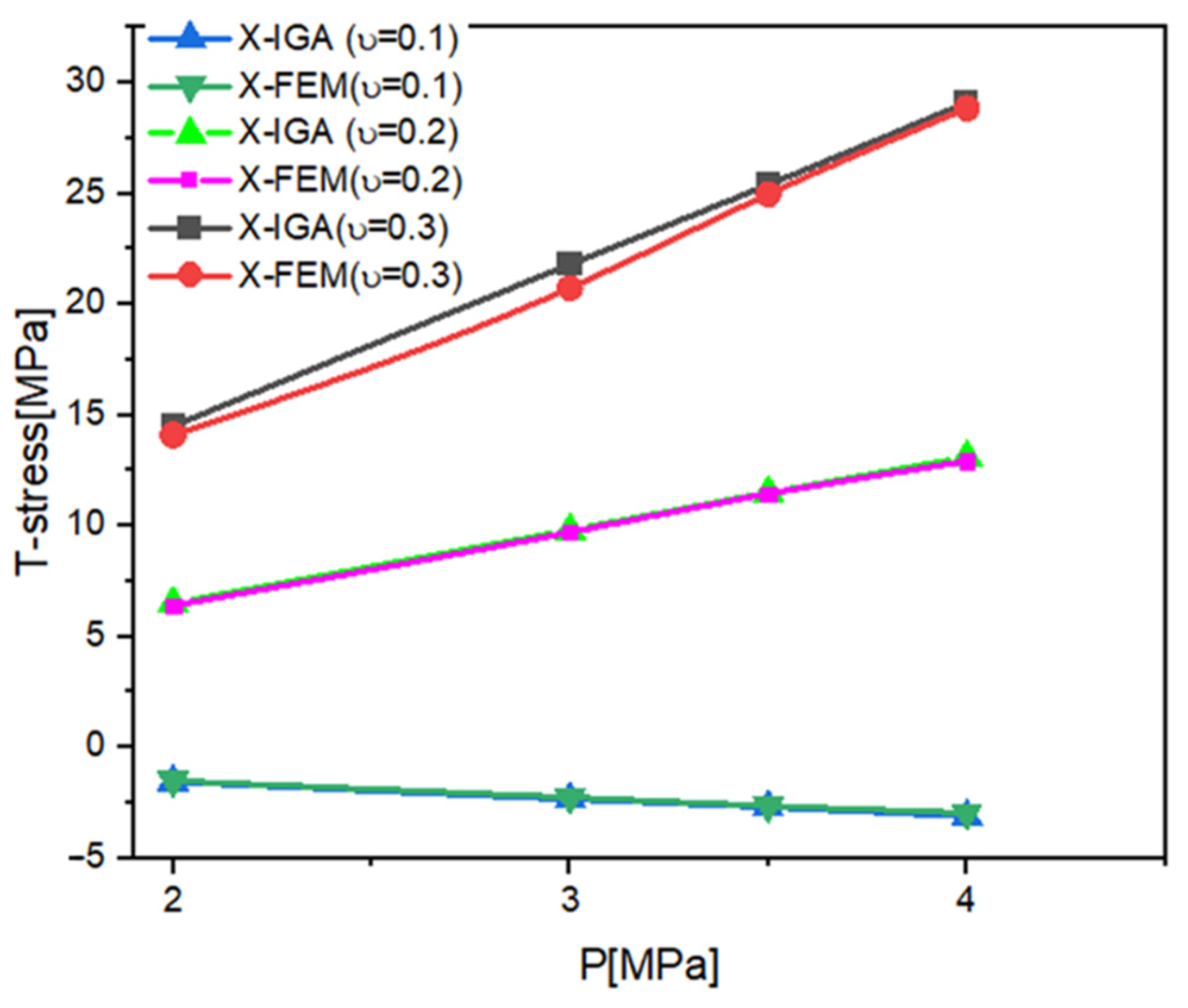
Figure 8 represents the variation of T-stress as a function of the ratio a/t, and Figure 9 shows the variation of T-stress as a function of internal pressure for different values of Poisson’s ratio v , with T-stress increasing as the absolute value of p rises. Furthermore, the X-IGA values are consistent with the X-FEM values provided by the Abaqus software. An internal radius of 100 and an exterior radius of 120 are used in the following computation.
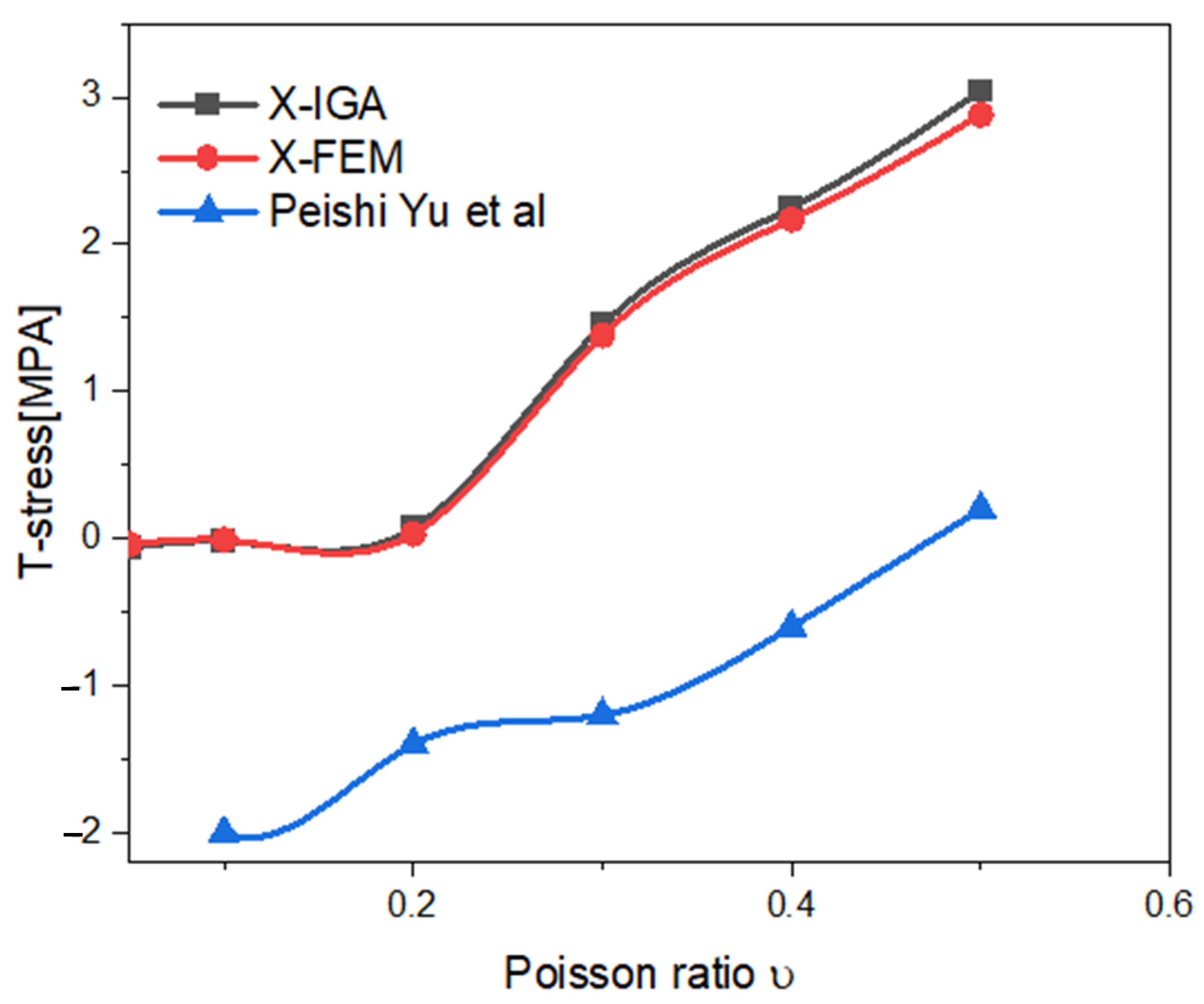
Figure 10 shows the variation of T as a function of Poisson’s ratio; we found the same variation for the two numerical approaches, X-FEM and X-IGA, with a 2.78 % difference; also it is clear that when the Poisson ratio grows, T-stress rises.
Table 4 presents the value of T0 derived by X-IGA and X-FEM for various a/t (0.3, 0.4, 0.5, 0.6) values, and the error calculated by Error = | X IGA X FEM | X FEM 100 . The resulting findings are accurate when compared to the X-FEM approach, with an error range of 0.12 to 4.6%.

4. Discussion

The purpose of this work is to investigate the problem of cracking in pipes using a parameter that better represents the fracture tip in order to predict crack propagation before damage occurs. The effect of Poisson’s ratio, internal pressure, and fracture size on T-stress were investigated. The computation is performed numerically by X-IGA, and we compared the results with X-FEM and previous research. The X-IGA produced accurate results that were equivalent to X-FEM; the error ranged from 0.3 to 4.6%, demonstrating the approach’s potency. The X-IGA method produces accurate fracture parameter calculations on cylindrical structures cracked under uniform pressure and can be used in the computation of more complex geometries. These results are identical to those of Montassir et al. [20]; in their X-IGA cracked pipe investigation, they obtained a 6.01% inaccuracy. On the other hand, there is the Fakoussi et al. [19] research, which used the (X-IGA) technique to detect the behavior of an external crack in a pipeline structure, performed using Abaqus/Standard software via a UEL subroutine. They achieved a 10.5% error rate. Nguyen-Thanh and Kun Zhou [42] similarly investigated the subject of cracking using X-IGA and discovered an error range of 13.44 to 0.8911%. Additionally, Wang and Dong [43] used the X-IGA approach to simulate thin plates and shells with through-thickness cracks and produced extremely accurate results. The X-IGA approach was also shown to be accurate on cracked functionally graded magneto-electro-elastic (FGMEE) materials [44]. Our results are reliable, so the geometry is built exactly using NURBS, which reduces the discretization error. We have also demonstrated in this manuscript the importance of considering T-stress in the evaluation of cracking problems, as T-stress is affected by a number of parameters.
T-stress is affected by the Poisson coefficient; T-stress rises as the Poisson’s ratio increases (see Figure 5), and this variation becomes more significant when Poisson’s ratio v exceeds 0.3. According to the findings, cracked pipes with a greater Poisson’s ratio are more easily damaged. The results are also compatible with Sladek, J. and Sladek, V. [45]; Toshio [46] also showed that the Poisson’s coefficient influences the T-stress; T increases with the increase in the Poisson’s ratio, one of the various three-dimensional geometries determined by finite element computations.
T-stress is negative for increasing a/t values until it approaches 0 for a/t = 0.6. We can deduce from these findings that the importance of T-stress is proportional to the crack size. These results are congruent with the findings of [47], in which the stress distributions of T-stress are computed using a finite element model of a through-wall-cracked pipe. The T-stress given in [47] results in an increase in T-stress for f 0.5 ≤ z/B < 1 and a reduction of T-stress for 0 < z/B ≤ 0.5, where z is the depth of the crack and B is the width of the pipe. However, Wang [48] and Sham [49] obtained an increase in T-stress with the crack size. T-stress has a significant impact on the size of hydrostatic triaxiality at the fracture tip elastic-plastic fields, as well as the crack tip constraint. Brugier [50] also demonstrated that fracture size affects T-stress. In the context of small cracks, T-stress increases the potential of fracture opening stresses;
σ 11 ( r , θ ) = K 1 2 π r f 11 ( θ ) + T
Taking σ 11 ( r , θ ) = σ c r , for the crack propagation, K 1 2 π r f 11 ( θ ) tends to a, if a tends to zero. At the fracture point, the first term becomes an insignificant interface to T.
lim a > 0 σ 11 ( r , θ ) = σ c r = T . So, T-stress plays the role of a crack opening, so its significance changes with the size of the cracks.
Figure 9 illustrates the influence of internal pressure on T-stress; it is apparent that the absolute value of T increases as pressure increases. T-stress takes negative values for v < 0.2 and positive ones for v 0.2 ; a negative T value reduces the angle of fracture start, whereas a positive T value increases it [2]. The sign of T-stress also indicates the stability of the direction of crack propagation; T-stress negative gives a stable direction, and for T positive it is unstable [1]. In relation to the crack propagation direction, Fayed et al. investigated the effect of T-stress on crack propagation direction using maximum tangential stress (MTS). The crack propagates in the direction of maximum tangential stress, according to the MTS principle. They discovered that the overall crack directions do not coincide with the crack’s initial direction. Many studies have concluded that tangential stress is affected by the T-Stress. MTS is transformed into generalized maximum tangential stress (GMTS), which incorporates the constraint T into the stress expression. The plastic zone expands in response to negative T-stress [14]. The sign of T-stress also has a significant effect on the magnitude of the hydrostatic triaxiality near the crack tip elasto-plastic fields and influences crack tip stress. Positive T-stress can increase crack tip stress triaxiality and result in high crack tip constraint, whereas negative T-stress can decrease crack tip stress triaxiality and result in crack tip constraint loss.

5. Conclusions

Using a numerical calculation performed by X-IGA and X-FEM, we investigated the problem of cracks in a pipe under internal pressure by studying the second term of the Williams expression, T-stress. X-IGA produces accurate results by combining precise geometry with the NURBS function, and crack enrichment using the level set tool. T-stress is obtained by the stress difference method (SDM). SDM is an efficient and simple method to calculate the T-stress. The results obtained showed that T-stress is affected by several parameters; it rises with fracture size and can play the role of a crack opening. Hence, its value changes with the size of the cracks. Additionally, T-stress increases with the rise in the Poisson’s ratio; cracked pipes with a higher Poisson’s ratio are more susceptible to deterioration. In addition, T-stress is affected by internal pressure; the absolute value of T increases as p increases. This demonstrates the importance of this powerful parameter.
The successful results acquired by X-IGA provide a vision for dealing with difficult three-dimensional cracking problems.

Author Contributions

Conceptualization, K.Y., S.M., H.M. and A.E.; methodology, K.Y., S.M., H.M. and A.E.; software, K.Y., S.M., H.M. and A.E.; validation, K.Y., S.M., H.M., A.E., M.L.S. and S.V.; formal analysis K.Y., S.M., H.M., A.E., M.L.S. and S.V.; investigation, K.Y., S.M., H.M. and A.E.; resources, K.Y., S.M., H.M., A.E., M.L.S. and S.V.; data curation, K.Y., S.M., H.M. and A.E.; writing—original draft preparation, K.Y., S.M., H.M. and A.E.; writing—review and editing, K.Y., S.M., H.M., A.E., M.L.S. and S.V.; visualization, K.Y., S.M., H.M., A.E., M.L.S. and S.V.; supervision, K.Y., S.M., H.M., A.E., M.L.S. and S.V.; project administration, K.Y., S.M., H.M. and A.E.; funding acquisition, K.Y., S.M., H.M. and A.E. All authors have read and agreed to the published version of the manuscript.

Funding

This research received no external funding. The APC was funded by Transilvania University of Brasov.

Institutional Review Board Statement

Not applicable.

Informed Consent Statement

Not applicable.

Data Availability Statement

Not applicable.

Acknowledgments

The authors thank Catalin Iulian Pruncu from the Politecnico di Bari, Italy, for proofreading assistance and overall guidance, which made drafting this work possible.

Conflicts of Interest

The authors declare no conflict of interest.

References

  1. Yakoubi, K.; Montassir, S.; Moustabchir, H.; Elkhalfi, A.; Pruncu, C.I.; Arbaoui, J.; Farooq, M.U. An Extended Finite Element Method (XFEM) Study on the Elastic T-Stress Evaluations for a Notch in a Pipe Steel Exposed to Internal Pressure. Mathematics 2021, 9, 507. [Google Scholar] [CrossRef]
  2. Shahani, A.; Tabatabaei, S. Effect of T-stress on the fracture of a four point bend specimen. Mater. Des. 2009, 30, 2630–2635. [Google Scholar] [CrossRef]
  3. Hou, C.; Wang, Z.; Jin, X.; Ji, X.; Fan, X. Determination of SIFs and T-stress using an over-deterministic method based on stress fields: Static and dynamic. Eng. Fract. Mech. 2021, 242, 107455. [Google Scholar] [CrossRef]
  4. Gupta, M.; Alderliesten, R.C.; Benedictus, R. A review of T-stress and its effects in fracture mechanics. Eng. Fract. Mech. 2015, 134, 218–241. [Google Scholar] [CrossRef]
  5. Lieurade, H.P.; Hariri, S. Estimation des Contraintes de Confinements dans des Structures Portant des Entailles. 2009, p. 320. Available online: https://hal.univ-lorraine.fr/tel-01752641/document (accessed on 16 May 2022).
  6. Song, C.; Ooi, E.T.; Natarajan, S. A review of the scaled boundary finite element method for two-dimensional linear elastic fracture mechanics. Eng. Fract. Mech. 2018, 187, 45–73. [Google Scholar] [CrossRef] [Green Version]
  7. Cotterell, B.; Rice, J. Slightly curved or kinked cracks. Int. J. Fract. 1980, 16, 155–169. [Google Scholar] [CrossRef]
  8. Miao, X.-T.; Zhou, C.-Y.; Lv, F.; He, X.-H. Three-dimensional finite element analyses of T-stress for different experimental specimens. Theor. Appl. Fract. Mech. 2017, 91, 116–125. [Google Scholar] [CrossRef]
  9. Suo, Y.-R.; Zhou, Y.-B.; Liu, G.-T. Effect of T-stress on the fracture in an infinite two-dimensional decagonal quasicrystals of a cruciform crack with unequal arms. Int. J. Solids Struct. 2021, 232, 111181. [Google Scholar] [CrossRef]
  10. Smith, D.; Ayatollahi, M.; Pavier, M. The role of T—stress in brittle fracture for linear elastic materials under mixed—mode loading. Fatigue Fract. Eng. Mater. Struct. 2001, 24, 137–150. [Google Scholar] [CrossRef]
  11. Mirsayar, M.M. On fracture of kinked interface cracks—The role of T-stress. Mater. Des. 2014, 61, 117–123. [Google Scholar] [CrossRef]
  12. Ayatollahi, M.R.; Aliha, M.R.M. Fracture toughness study for a brittle rock subjected to mixed mode I/II loading. Int. J. Rock Mech. Min. Sci. 2007, 44, 617–624. [Google Scholar] [CrossRef]
  13. Matvienko, Y.G. The effect of crack-tip constraint in some problems of fracture mechanics. Eng. Fail. Anal. 2020, 110, 104413. [Google Scholar] [CrossRef]
  14. Jayadevan, K.R.; Narasimhan, R.; Ramamurthy, T.S.; Dattaguru, B. Effect of T-stress and loading rate on crack initiation in rate sensitive plastic materials. Int. J. Solids Struct. 2002, 39, 1757–1775. [Google Scholar] [CrossRef]
  15. Ayatollahi, M.R.; Nejati, M.; Ghouli, S. The finite element over-deterministic method to calculate the coefficients of crack tip asymptotic fields in anisotropic planes. Eng. Fract. Mech. 2020, 231, 106982. [Google Scholar] [CrossRef]
  16. Cottrell, J.A.; Hughes, T.J.R.; Bazilevs, Y. Isogeometric Analysis Toward Integration of CAD and FEA; John Wiley & Sons: London, UK, 2009. [Google Scholar]
  17. Hughes, T.J.R.; Cottrell, J.A.; Bazilevs, Y. Isogeometric analysis: CAD, finite elements, NURBS, exact geometry and mesh refinement. Comput. Methods Appl. Mech. Eng. 2005, 194, 4135–4195. [Google Scholar] [CrossRef] [Green Version]
  18. Lai, W.; Yu, T.; Bui, T.Q.; Wang, Z.; Curiel-Sosa, J.L.; Das, R.; Hirose, S. 3-D elasto-plastic large deformations: IGA simulation by Bézier extraction of NURBS. Adv. Eng. Softw. 2017, 108, 68–82. [Google Scholar] [CrossRef] [Green Version]
  19. El Fakkoussi, S.; Moustabchir, H.; Elkhalfi, A.; Pruncu, C.I. Application of the Extended Isogeometric Analysis (X-IGA) to Evaluate a Pipeline Structure Containing an External Crack. J. Eng. 2018, 2018, 4125765. [Google Scholar] [CrossRef] [Green Version]
  20. Montassir, S.; Moustabchir, H.; Elkhalfi, A.; Scutaru, M.L.; Vlase, S. Fracture Modelling of a Cracked Pressurized Cylindrical Structure by Using Extended Iso-Geometric Analysis (X-IGA). Mathematics 2021, 9, 2990. [Google Scholar] [CrossRef]
  21. Yixiu, S.; Yazhi, L. A Simple and Efficient X-FEM Approach for Non-planar Fatigue Crack Propagation. Procedia Struct. Integr. 2016, 2, 2550–2557. [Google Scholar] [CrossRef] [Green Version]
  22. Schiavone, A. Abeygunawardana-Arachchige, G.; Silberschmidt, V.V. Crack initiation and propagation in ductile specimens with notches: Experimental and numerical study. Acta Mech. 2016, 227, 203–215. [Google Scholar] [CrossRef] [Green Version]
  23. Cottrell, J.A.; Reali, A.; Bazilevs, Y.; Hughes, T.J.R. Isogeometric analysis of structural vibrations. Comput. Methods Appl. Mech. Eng. 2006, 195, 5257–5296. [Google Scholar] [CrossRef] [Green Version]
  24. Shojaee, S.; Valizadeh, N.; Izadpanah, E.; Bui, T.; Vu, T.-V. Free vibration and buckling analysis of laminated composite plates using the NURBS-based isogeometric finite element method. Compos. Struct. 2012, 94, 1677–1693. [Google Scholar] [CrossRef]
  25. Kapoor, H.; Kapania, R.K. Geometrically nonlinear NURBS isogeometric finite element analysis of laminated composite plates. Compos. Struct. 2012, 94, 3434–3447. [Google Scholar] [CrossRef]
  26. Wang, Y.; Wang, Z.; Xia, Z.; Hien Poh, L. Structural Design Optimization Using Isogeometric Analysis: A Comprehensive Review. Comput. Model. Eng. Sci. 2018, 117, 455–507. [Google Scholar] [CrossRef] [Green Version]
  27. Yadav, A.; Godara, R.K.; Bhardwaj, G. A review on XIGA method for computational fracture mechanics applications. Eng. Fract. Mech. 2020, 230, 107001. [Google Scholar] [CrossRef]
  28. Nguyen-Thanh, N.; Valizadeh, N.; Nguyen, M.N.; Nguyen-Xuan, H.; Zhuang, X.; Areias, P.; Zi, G.; Bazilevs, Y.; De Lorenzis, L.; Rabczuk, T. An extended isogeometric thin shell analysis based on Kirchhoff–Love theory. Comput. Methods Appl. Mech. Eng. 2015, 284, 265–291. [Google Scholar] [CrossRef]
  29. Hou, W.; Jiang, K.; Zhu, X.; Shen, Y.; Hu, P. Extended isogeometric analysis using B++ splines for strong discontinuous problems. Comput. Methods Appl. Mech. Eng. 2021, 381, 113779. [Google Scholar] [CrossRef]
  30. Singh, S.K.; Singh, I.V.; Mishra, B.K.; Bhardwaj, G.; Bui, T.Q. A simple, efficient and accurate Bézier extraction based T-spline XIGA for crack simulations. Theor. Appl. Fract. Mech. 2017, 88, 74–96. [Google Scholar] [CrossRef]
  31. Ghorashi, S.S.; Valizadeh, N.; Mohammadi, S. Extended isogeometric analysis for simulation of stationary and propagating cracks: Xiga for simulation of stationary and propagating cracks. Int. J. Numer. Methods Eng. 2012, 89, 1069–1101. [Google Scholar] [CrossRef]
  32. El Fakkoussi, S.; Moustabchir, H.; Elkhalfi, A.; Pruncu, C.I. Computation of the stress intensity factor KI for external longitudinal semi-elliptic cracks in the pipelines by FEM and XFEM methods. Int. J. Interact. Des. Manuf. IJIDeM 2019, 13, 545–555. [Google Scholar] [CrossRef] [Green Version]
  33. Kfouri, A.P. Some evaluations of the elastic T-term using Eshelby’s method. Int. J. Fract. 1986, 30, 301–315. [Google Scholar] [CrossRef]
  34. Yang, B.; Ravi-Chandar, K. Evaluation of elastic T-stress by the stress difference method. Eng. Fract. Mech. 1999, 64, 589–605. [Google Scholar] [CrossRef]
  35. Rungamornrat, J.; Mear, M.E. A weakly-singular SGBEM for analysis of cracks in 3D anisotropic media. Comput. Methods Appl. Mech. Eng. 2008, 197, 4319–4332. [Google Scholar] [CrossRef]
  36. Phongtinnaboot, W.; Rungamornrat, J.; Chintanapakdee, C. Modeling of cracks in 3D piezoelectric finite media by weakly singular SGBEM. Eng. Anal. Bound. Elem. 2011, 35, 319–329. [Google Scholar] [CrossRef]
  37. Ghorashi, S.S.; Mohammadi, S.; Sabbagh-Yazdi, S.-R. Orthotropic enriched element free Galerkin method for fracture analysis of composites. Eng. Fract. Mech. 2011, 78, 1906–1927. [Google Scholar] [CrossRef]
  38. Li, J.; Liu, J.Z.; Korakianitis, T.; Wen, P.H. Finite block method in fracture analysis with functionally graded materials. Eng. Anal. Bound. Elem. 2017, 82, 57–67. [Google Scholar] [CrossRef]
  39. Fallah, N.; Nikraftar, N. Meshless finite volume method for the analysis of fracture problems in orthotropic media. Eng. Fract. Mech. 2018, 204, 46–62. [Google Scholar] [CrossRef]
  40. Kim, J.-H.; Paulino, G.H. T-stress, mixed-mode stress intensity factors, and crack initiation angles in functionally graded materials: A unified approach using the interaction integral method. Comput. Methods Appl. Mech. Eng. 2003, 192, 1463–1494. [Google Scholar] [CrossRef]
  41. Shah, P.D.; Tan, C.L.; Wang, X. T-stress solutions for two-dimensional crack problems in anisotropic elasticity using the boundary element method. Fatigue Fract. Eng. Mater. Struct. 2006, 29, 343–356. [Google Scholar] [CrossRef]
  42. Nguyen-Thanh, N.; Zhou, K. Extended isogeometric analysis based on PHT-splines for crack propagation near inclusions. Int. J. Numer. Methods Eng. 2017, 112, 1777–1800. [Google Scholar] [CrossRef]
  43. Yang, H.S.; Dong, C.Y. Adaptive extended isogeometric analysis based on PHT-splines for thin cracked plates and shells with Kirchhoff–Love theory. Appl. Math. Model. 2019, 76, 759–799. [Google Scholar] [CrossRef]
  44. Singh, S.K.; Singh, I.V. Extended isogeometric analysis for fracture in functionally graded magneto-electro-elastic material. Eng. Fract. Mech. 2021, 247, 107640. [Google Scholar] [CrossRef]
  45. Sladek, J.; Sladek, V. Evaluation of the Elastic T-stress in Three-dimensional Crack Problems Using an Integral Formula. Int. J. Fract. 2000, 101, 47–52. [Google Scholar] [CrossRef]
  46. Toshio, N.; Parks, D.M. Determination of elastic T-stress along three-dimensional crack fronts using an interaction integral. Int. J. Solids Struct. 1992, 29, 1597–1611. [Google Scholar] [CrossRef]
  47. Yu, P.; Wang, Q.; Zhang, C.; Zhao, J. Elastic T -stress and I-II mixed mode stress intensity factors for a through-wall crack in an inner-pressured pipe. Int. J. Press. Vessels Pip. 2018, 159, 67–72. [Google Scholar] [CrossRef]
  48. Wang, X. Elastic T-stress solutions for semi-elliptical surface cracks in finite thickness plates. Eng. Fract. Mech. 2003, 70, 731–756. [Google Scholar] [CrossRef]
  49. Sham, T.-L. The determination of the elastic T-term using higher order weight functions. Int. J. Fract. 1991, 48, 81–102. [Google Scholar] [CrossRef]
  50. Brugier, F. Modèle Condensé de Plasticité Pour la Fissuration et Influence de la Contrainte T; Université Paris-Saclay (ComUE): Paris, France, 2017; Available online: https://tel.archives-ouvertes.fr/tel-01587740/file/74336_BRUGIER_2017_archivage.pdf (accessed on 16 May 2022).
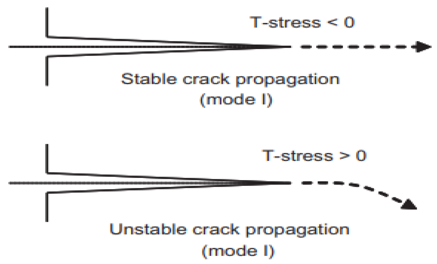
Figure 1. The stability of the crack propagation as a function of T.
Symmetry 14 01065 g001
Figure 2. The principle of isogeometric IGA analysis compared to FEM.
Symmetry 14 01065 g002
Figure 3. Steps in the enrichment method; when the crack propagates, enrichment at the crack front becomes discontinuous enrichment, and nodes (not enriched) become enriched [32].
Symmetry 14 01065 g003
Figure 4. Crack tip coordinate [20].
Symmetry 14 01065 g004
Figure 5. Geometry construction: (a) crack size ranges from 0.2 to 0.45, (b) mesh for X-IGA, (c) mesh used for X-FEM.
Symmetry 14 01065 g005
Figure 6. The distribution of Von Mises stress with X-FEM on the right and X-IGA on the left.
Symmetry 14 01065 g006
Figure 7. T-Stress as a function of r computed by X-IGA.
Symmetry 14 01065 g007
Figure 8. The variation of T-stress/ σ 0 as function a/t.
Symmetry 14 01065 g008
Figure 9. T-stress as a function of internal pressure, for different values of Poisson’s ratio.
Symmetry 14 01065 g009
Figure 10. Variation of T-stress with Poisson ratio, by X-FEM and X-IGA.
Symmetry 14 01065 g010
Table 1. Mechanical characteristics of P264GH.
Young’s ModulusPoisson’s RatioYield StressElongation to Fracture
207,000 MPa0.3340 MPa35%
Table 2. Chemical composition of P264GH.
MaterialCMnSSipAl
Tested0.1350.6650.0020.1950.0270.027
Steel P264GH
(Standard EN10028.2-92)
0.1810.0150.40.0250.02
Table 3. Geometry properties and load.
Ri [mm]p [MPa]a [mm]t [mm]
1002.53–520
Table 4. Comparison of normalized T-stress solutions, T / σ 0 , from X-IGA calculation and solution from X-FEM, for different values of a/t. r .
a / t X-IGAX-FEMError [%]
0.3−25.26−25.000.12
0.4−3.89−3.812.09
0.5−1.14−1.113.6
0.6−10−44 × 10−4−zv
Publisher’s Note: MDPI stays neutral with regard to jurisdictional claims in published maps and institutional affiliations.