Article

Vibration Force Suppression of Magnetically Suspended Flywheel Based on Compound Repetitive Control

School of Aeronautics and Astronautics, Sun Yat-sen University, Guangzhou 510275, China
*
Author to whom correspondence should be addressed.
Symmetry 2022, 14(5), 949; https://doi.org/10.3390/sym14050949
Submission received: 6 April 2022 / Revised: 30 April 2022 / Accepted: 3 May 2022 / Published: 6 May 2022

Abstract

:
To realize the hyperstatic performance index of a magnetically suspended flywheel and simultaneously suppress the vibration force caused by mass imbalance and sensor runout, a compound control method based on a repetitive controller and displacement force compensation of the synchronous force is proposed. First, the mechanism of different interference vibration forces is analyzed by establishing a model of the magnetically suspended flywheel. The analysis shows that the x–y direction is symmetric, and the flywheel structure has symmetry. Second, considering the symmetry of the x- and y-directions, the x-direction is taken as an example for analysis, the parameter design and stability analysis are carried out, and the range of parameters of the compound repetitive control method is obtained. Finally, a flywheel with different speeds is simulated. It was found that the vibration force of each frequency can be suppressed by the compound control method, and the inhibition rate of the vibration force can reach as much as 95%. The results show that the unbalanced vibration and vibration force caused by the sensor runout can be effectively suppressed by using the compound repetitive control method.

1. Introduction

Magnetic bearings are becoming more widely used because of such advantages as no friction, no need for grease, and long life [1]. The application of magnetic bearings also has a unique advantage, as it can be used as the carrier of the rotor and can control the vibration of the high-speed rotor through electromagnetic control [2]. The application of magnetically suspended flywheels makes the hyperstatic attitude control mechanism possible [3,4,5]. The rotor of the magnetically suspended flywheel is similar to the high-speed rotor in other fields in terms of processing error and uneven material aspect. This is because the unbalanced mass cannot be removed completely, and the unbalanced mass becomes the main reason for the rotor vibration. At the same time, the sensor runout also the main dominant resource of the vibration of the flywheel [6,7].
Currently, research on mass imbalance vibration suppression is mainly divided into two categories [8,9,10,11]. One is the zero-displacement method, which makes the inertia axis of the rotor coincide with its geometric axis through control to improve the accuracy of the rotation center, and the other is zero vibration, so that the vibration of the rotor is not transmitted to the stator, reducing the influence of the rotor system on the base. Zero vibration is often realized mainly by suppressing synchronous current, using the notch filter method, and using the least-mean-squares method [12]. Herzog proposed a general notch filter to enhance the stability of the system by introducing a matrix into the notch filter [13]. As a simple and effective method, the notch filter is favored by many scholars. Zheng studied the parallel and series influence of a notch filter connected to the original controller and found that the parallel mode has a deeper notch depth and faster convergence [14]. These studies are mainly aimed at the zero synchronous current. To improve the suppression accuracy of the vibration force further, the compensation of the synchronous displacement stiffness force has also been considered [15]. Xu proposed a phase-shift notch filter with phase compensation, and its parameter design is easier than that of the general notch filter [16]. Chen proposed a double-loop control method to reduce the influence of the power amplifier and provide precise vibration suppression by using different control loops at high and low speeds [17]. An adaptive notch filter was proposed to change the notch coefficient of the notch filter into a speed-related quantity to improve the adaptability of the notch filter [18]. Recently, Peng [19] adopted a second-order notch filter to suppress the vibration in the full speed range. However, these studies did not consider the influence of sensor runout.
Setiawan used the bias current excitation to eliminate the disturbance of mass imbalance and sensor runout, but only considered the synchronous disturbances [20]. Sensor runout also produces harmonic vibrations, so multiple notch filters are used in series to suppress the harmonic current [21]. However, the design can become complex with increasing harmonic order, and the tracking and suppression effect of repetitive controllers on periodic disturbances has been verified in the field of electrical engineering [22,23]. Xu used a repetitive control method to suppress the harmonic current of the magnetic suspension flywheel system [24]. Through improvement of the repetitive control method, the effect of harmonic current suppression was better [25,26,27,28,29], but the displacement stiffness force was not considered in the research. Therefore, it is necessary to find a method that can suppress the mass imbalance and the multiple frequency vibration force of the sensor runout simultaneously to realize the suppression of high-precision microvibration.
In this report, a compound repetitive control method is proposed to suppress the vibration force generated by the multiple-frequency current through the repetitive control method, and then to compensate the vibration force generated by the displacement of the same frequency to achieve the purpose of simultaneously suppressing all the force generated by the mass imbalance and the sensor runout. Then, the stability of the method is analyzed, and the parameter is designed. The effectiveness of the compound control method is verified by simulation.
This paper is structured as follows. In Section 2, the magnetically suspended flywheel system is described. In Section 3, the compound repetitive control method for vibration force suppression is introduced and the stability of this method is discussed. The parameters are designed, and simulation results are provided to verify the validity of the proposed method in Section 4. A conclusion is given in Section 5.

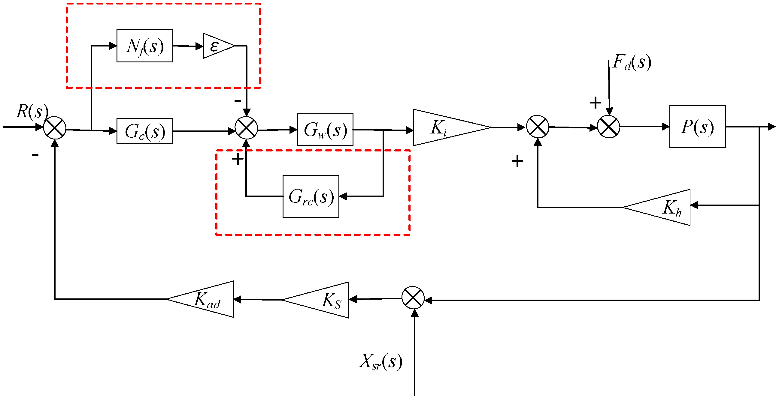
2. Modeling of Magnetically Suspended Flywheel System

The flywheel studied in this paper is a five degrees-of-freedom suspension. The structure of the magnetically suspended flywheel is shown in Figure 1. On the two radial degrees of freedom, the translation control of the rotor is realized by active magnetic bearings. On the other three degrees of freedom, the stability of the rotor is realized by using the magnetic resistance between the stator and the rotor of the passive magnetic bearing. The main focus of this study was the active vibration control of two degrees of radial freedom [9].
The flywheel rotor is cylindrical and has symmetry in the radial direction. According to Newton’s second law, the equation of motion of two radial degrees of freedom can be expressed as
m x ¨ = F c x m y ¨ = F c y
where m is the mass of the rotor, F c x is the resultant force in the x-direction, and F c y is the resultant force in the y-direction. Considering the symmetry of the x- and y-directions, for convenience, the x-direction is taken as an example for analysis. The electromagnetic force in the maglev system is linearized at the equilibrium point, and the unbalanced mass vibration is considered. The dynamic equation is as follows:
m x ¨ = K h x + K i i + F d
where K h and K i represent the displacement stiffness coefficient and current stiffness coefficient, respectively, and F d is the unbalanced force, which can be expressed as
F d = e m Ω 2 cos ( Ω + φ )
where e is the unbalanced coefficient, Ω is the rotational speed, and φ is the initial angle of the unbalanced force.
The sensor runout can be expressed as [30]
X s r = l = 1 n e s r sin ( n Ω + α )
where n is the harmonic order, e s r is the sensor runout, and α is the initial angle of the sensor runout.
Figure 2 shows the block diagram of the x-direction, in which G c ( s ) is the proportional–integral–derivative controller of the original system, G w ( s ) is the power amplifier, P ( s ) is the transfer function of the rotor system, and R(s) is the reference signal. K a d and K s are, respectively, the coefficient of the sampling and displacement sensors.
According to the control block diagram, taking F d ( s ) and X s r ( s ) as the input and F ( s ) as the output, the following transfer function is obtained:
F ( s ) = G d ( s ) F d ( s ) + G s r ( s ) X s r ( s ) = S ( s ) [ ( K h P ( s ) K a d K s K i G w ( s ) G c ( s ) P ( s ) ) F d K a d K i K s G w ( s ) G c ( s ) X s r ( s ) ]
where S ( s ) is
S ( s ) = 1 1 K h P ( s ) + K a d K s K i G w ( s ) G c ( s ) P ( s )
Equation (5) demonstrates that the unbalanced mass only produces a vibration force of the same frequency, which includes the current stiffness force and the displacement stiffness force, while the displacement sensor runout enters the system through the feedback of the sensor and produces the current stiffness force. Therefore, it is possible to achieve zero vibration force only by suppressing the vibration caused by various interferences at the same time.

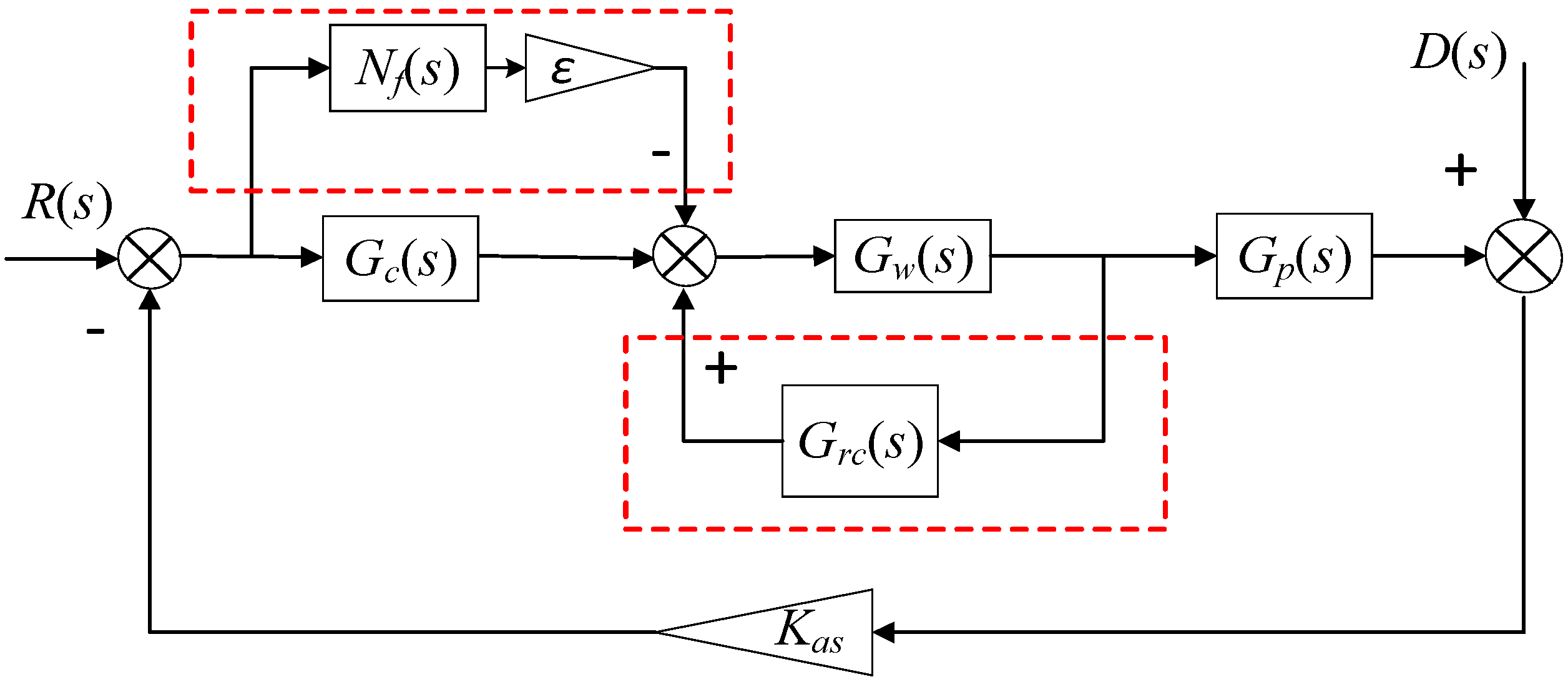
3. Compound Repetitive Control Method for Vibration Force Suppression

3.1. Overview of the Compound Repetitive Control Method

The repetitive control method mainly uses the internal model principle to introduce the repetitive signal consistent with the interference signal into the system to achieve the control method of suppressing or tracking the signal. In this study, the repetitive control method is initially used to suppress the harmonic current caused by the sensor and imbalance. Then, the same frequency phase shift notch filter is used to compensate for the displacement stiffness force introduced by the imbalance. The control block diagram of the compound control method used to suppress the full frequency vibration force of the magnetic suspension flywheel is shown in Figure 3.
Here, G r c ( s ) is the repetitive controller, the signal introduction point is the output current of the power amplifier, and the insertion point is the forward control signal of the power amplifier to reduce the influence of the power amplifier on the system. The signal introduction point of the phase-shift notch filter N f ( s ) is the comparison point between the reference signal and the displacement feedback signal. Then, the same frequency signal of the system is obtained, followed by the serial connection displacement stiffness force compensation coefficient ε . The insertion point is the output signal of G c ( s ) to realize the compensation of the same frequency displacement stiffness force. Finally, the full frequency vibration dynamic suppression of the magnetically suspended flywheel is realized through the compound method.

3.2. Suppression Principle of the Compound Control Method

According to the control block diagram, for the convenience of analysis, G p ( s ) = K i P ( s ) 1 K h P ( s ) , F d ( s ) and X s r ( s ) are recorded as interference input D(s), and K a s = K s K a d . The equivalent control block diagram is shown in Figure 4.
Here, G r c ( s ) is the repetitive controller, and its detailed control block diagram is shown in Figure 5. Furthermore, G f ( s ) is a medium- and low-frequency phase compensator, k r c is the gain of the repetitive controller, and Q ( s ) is the low-pass filter. This will satisfy Q ( ω ) 1 when ω < ω c , ω c is the cutoff frequency, and it can also be taken as a constant of less than 1. In addition, e - T 0 s is the time delay link [24].
To correct the phase delay of the system at a high frequency, the e T 1 s phase lead link is used to correct the high-frequency phase of the repetitive controller.
As the control block diagram shows, the transfer function of the repetitive controller with e T 1 s is as follows:
G r c ( s ) = G f ( s ) Q ( s ) K r c e T 0 s 1 Q ( s ) e T 0 s e T 1 s
With the interference D ( s ) as the input and the current I ( s ) as the output, the transfer function after adding the repetitive controller is
S 1 ( s ) = G c ( s ) G w ( s ) 1 G r c ( s ) G w ( s ) + G c ( s ) G w ( s ) G p ( s ) K a s = G c ( s ) G w ( s ) ( 1 Q ( s ) e T 0 s ) 1 + G c ( s ) G w ( s ) G p ( s ) K a s [ 1 + G w ( s ) G f ( s ) Q ( s ) K r c + G c ( s ) G w ( s ) G p ( s ) K a s ] e T 0 s
As (8) shows, when ω = k ω 0 , k = 1 , 2 , 3 , ω ( 0 , ω c ) , ω 0 is the basic frequency of interference, ω c is the cutoff frequency, Q ( s ) is a low-pass filter less than 1, and e T 0 s 1 , then current I ( s ) 0 . Thus, this method can effectively suppress harmonic current.
In Figure 4, N f ( s ) is a phase-shift notch filter whose transfer function can be expressed as [16]
N f ( s ) = s cos ϕ Ω sin ϕ s 2 + Ω 2
where Ω is the rotation speed of the rotor, and ϕ is the phase-shift angle to ensure the stability of the closed-loop system. We can set different phase-shift angles according to the different speeds.
where ε = k K h K i is the displacement stiffness force compensation coefficient. The k can also introduce a switch strategy depending on the speeds. Then, we can get an adjustable convergence rate. The displacement stiffness force of the flywheel is compensated for by the notch filter, and the same frequency displacement stiffness force of the flywheel is eliminated.

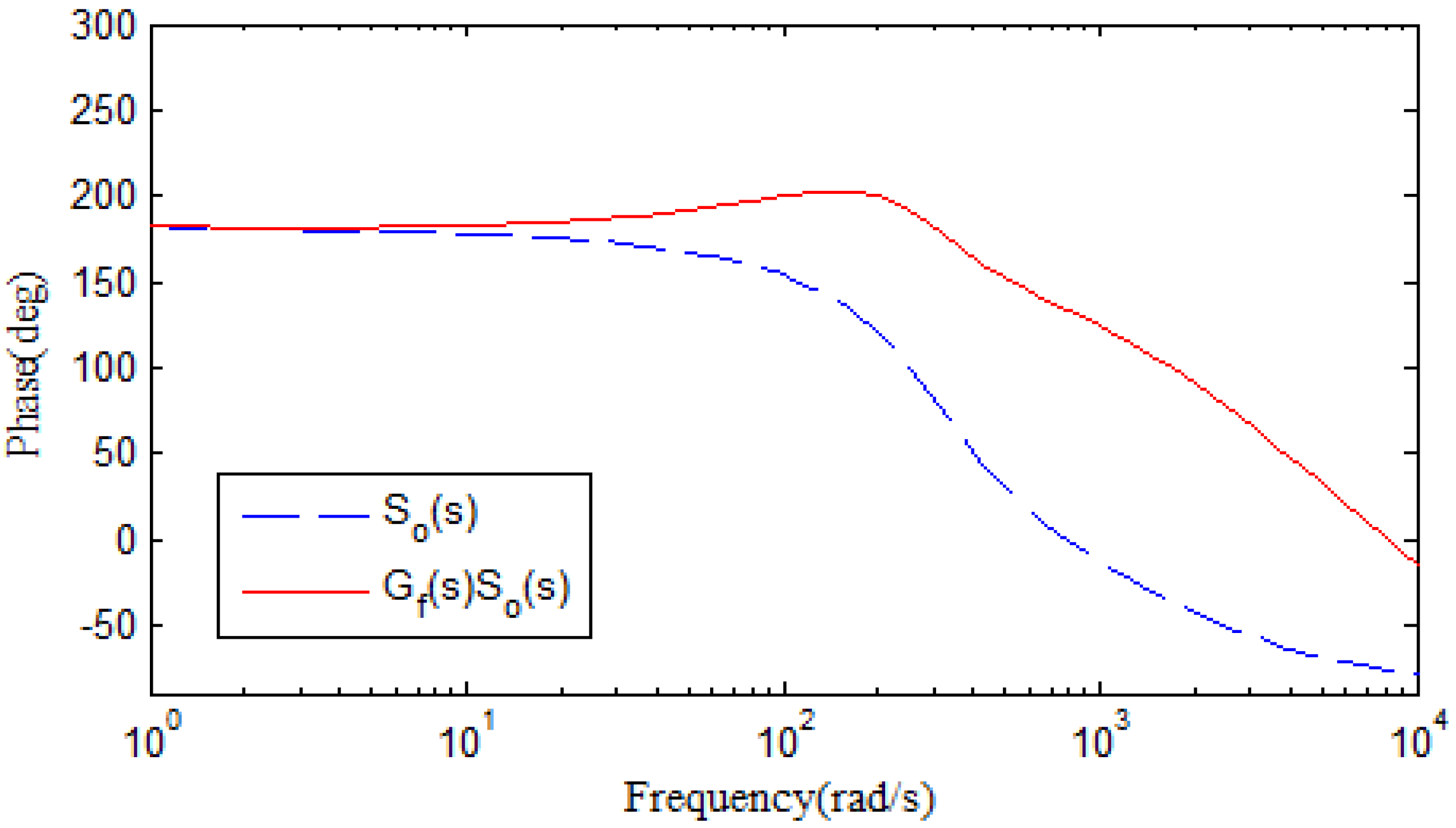
3.3. Stability Analysis of the Compound Control Method

The stability analysis of the compound method is carried out sequentially. First, the stability without compensation of the same frequency displacement stiffness is analyzed, and then the stability of the compound control method is analyzed based on system stability. The characteristic equation of the root of (8) is
1 + G c ( s ) G w ( s ) G p ( s ) K s [ 1 + G w ( s ) G f ( s ) Q ( s ) K r c + G c ( s ) G w ( s ) G p ( s ) K s ] e T 0 s = 0
It can be rewritten as
M ( s ) N ( s ) e T 0 s = 0
where
M ( s ) = 1 + G c ( s ) G w ( s ) G p ( s ) K a s N ( s ) = 1 + G w ( s ) G f ( s ) Q ( s ) K r c + G c ( s ) G w ( s ) G p ( s ) K a s
According to the definition of the regeneration spectrum [7],
R ( ω ) = N ( s ) M ( s ) s = j ω = 1 + G f ( s ) Q ( s ) K r c e T 1 s G w ( s ) 1 + G c ( s ) G w ( s ) G p ( s ) K a s s = j ω < 1
Note that
S 0 ( s ) = G w ( s ) 1 + G c ( s ) G w ( s ) G p ( s ) K a s
F ( s ) = G f ( s ) Q ( s ) S 0 ( s ) e T 1 s = L ( ω ) e j θ ( ω ) + T 1 ω
β = θ ( ω ) + T 1 ω
Then, (11) can be rewritten as
1 + K r c L ( ω ) e j β < 1
According to the Euler equation
e j β = cos β + j sin β
By substituting it into the equation, and taking K r c > 0 , the stability conditions of the system can be obtained as follows:
90 0 < β < 270 0
0 < K rc < 2 min cos β max L ( ω )
To compensate for the same frequency displacement stiffness force, N f ( s ) of the phase-shift notch filter is added to the above-mentioned stabilization system. According to the control block diagram, for the convenience of analysis, G w ( s ) = G w ( s ) 1 G w ( s ) G r c ( s ) , and the system error transfer function can be expressed as
E ( s ) = K s 1 + G c ( s ) G w ( s ) G p ( s ) K s ε N f ( s ) G w ( s ) G p ( s ) K a s
Note that
S 1 ( s ) = K s 1 + G c ( s ) G w ( s ) G p ( s ) K s
S 1 ( s ) = K s G w ( s ) G p ( s ) 1 + G c ( s ) G w ( s ) G p ( s ) K s
Equation (14) can be rewritten as
E ( s ) = S 1 ( s ) s 2 + Ω 2 s 2 + Ω 2 ε ( s cos ϕ + Ω sin ϕ ) S 1 ( s )
Therefore, the system can be stable only if the roots of the following characteristic equations are in the left half plane:
s 2 + Ω 2 ε ( s cos ϕ + Ω sin ϕ ) S 1 ( s ) = 0
The derivation of (16) with respect to ε is presented as
s ε s = j ω = 1 2 j ( sin ϕ + j cos ϕ ) S 1 ( j ω )
The root is in the left half plane, that is,
90 0 < s ε s = j ω < 90 0
Therefore, the stable condition is
90 0 < S 1 ( j ω ) ϕ < 9 0 0
In summary, the stability of the system can be guaranteed by selecting appropriate G f ( s ) , K r c , T 1 , and ϕ , so that the conditions of (12), (13), and (19) are met at the same time.

4. Parameter Design and Simulation Analysis

4.1. Parameter Design and Setting

To verify the suppression effect of the proposed control method, a simulation analysis was carried out using MATLAB/Simulink. The simulation parameters of the magnetic levitation flywheel system are shown in Table 1, and the mass unbalance and sensor runout parameters are listed in Table 2.
The phase diagram of S 0 ( s ) drawn according to the parameters is shown in Figure 6. It is known that the stability condition in (12) cannot be satisfied without compensation, and phase compensation is required in the middle- and high-frequency stages. The phase compensation is carried out by introducing G f ( s ) .
G f ( s ) = 0.0055 s + 1 0.00015 s + 1 0.0035 s + 1 0.00015 s + 1
Through its phase diagram, one can see that compensation is still needed in the high-frequency phase, i.e., the compensation e T 1 s should be added.
e T 1 s s = j ω = e j T 1 ω = e j N T s ω ( N = 1 , 2 , 3 )
The sample period Ts = 0.0001 s. The phase diagram of F ( s ) is drawn with different N, as shown in Figure 7. When N = 4, it can be obtained that β ( 134.5 ° , 215.2 ° ) with cutoff frequency ω c = 10000 r a d / s . The system meets the stability condition with the bigger phase margin than others. To facilitate the design, the low-pass filter Q ( s ) was selected as 0.98.
As can be seen from Figure 8, the maximum amplitude is 0.0049. According to (13), K r c should meet the following condition
0 < K r c < 2 cos ( 134.5 ° ) 0.0049 = 286.1
Finally, combined with the stability margin and the convergence rate, K r c is set as 155 to complete the design of the repetitive control parameters.
When designing the parameters of the displacement stiffness force compensation, the stability of the system including the repetitive controller is considered. Hence, the phase diagram containing the transfer function S 1 ( s ) of the repetitive controller mentioned above is drawn, as shown in Figure 9. To meet the requirements of the stability condition in (19), the supplementary phase compensation can be set in stages. When Ω 260 rad/s compensation is needed, and there is no need for phase 418 compensation, i.e., ϕ = 0 . The phase diagram after compensation when Ω > 260 rad/s and ϕ = 120 0 is as shown in Figure 9.

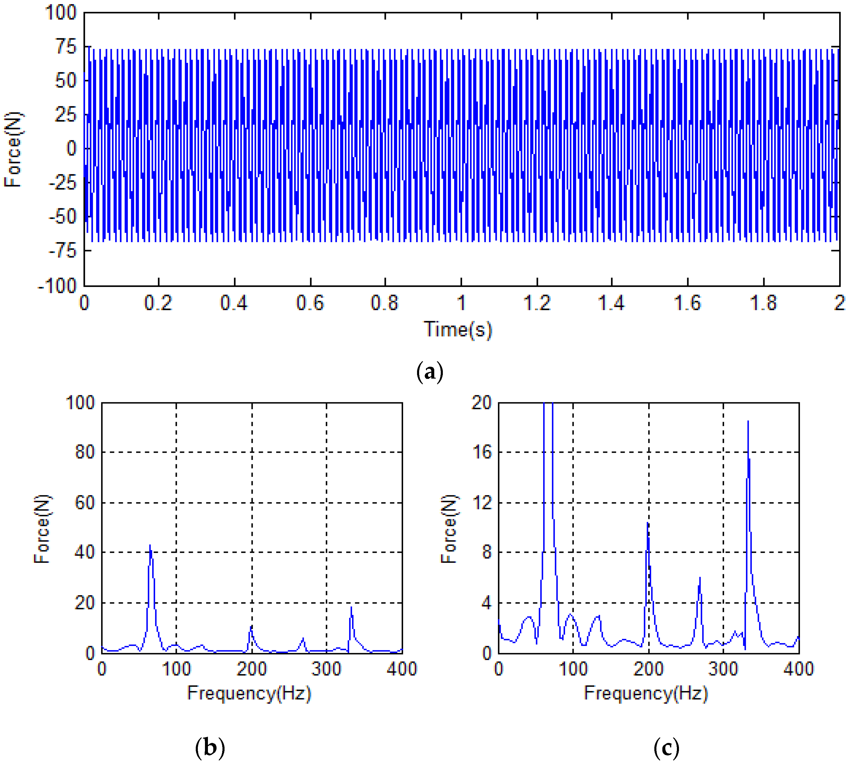
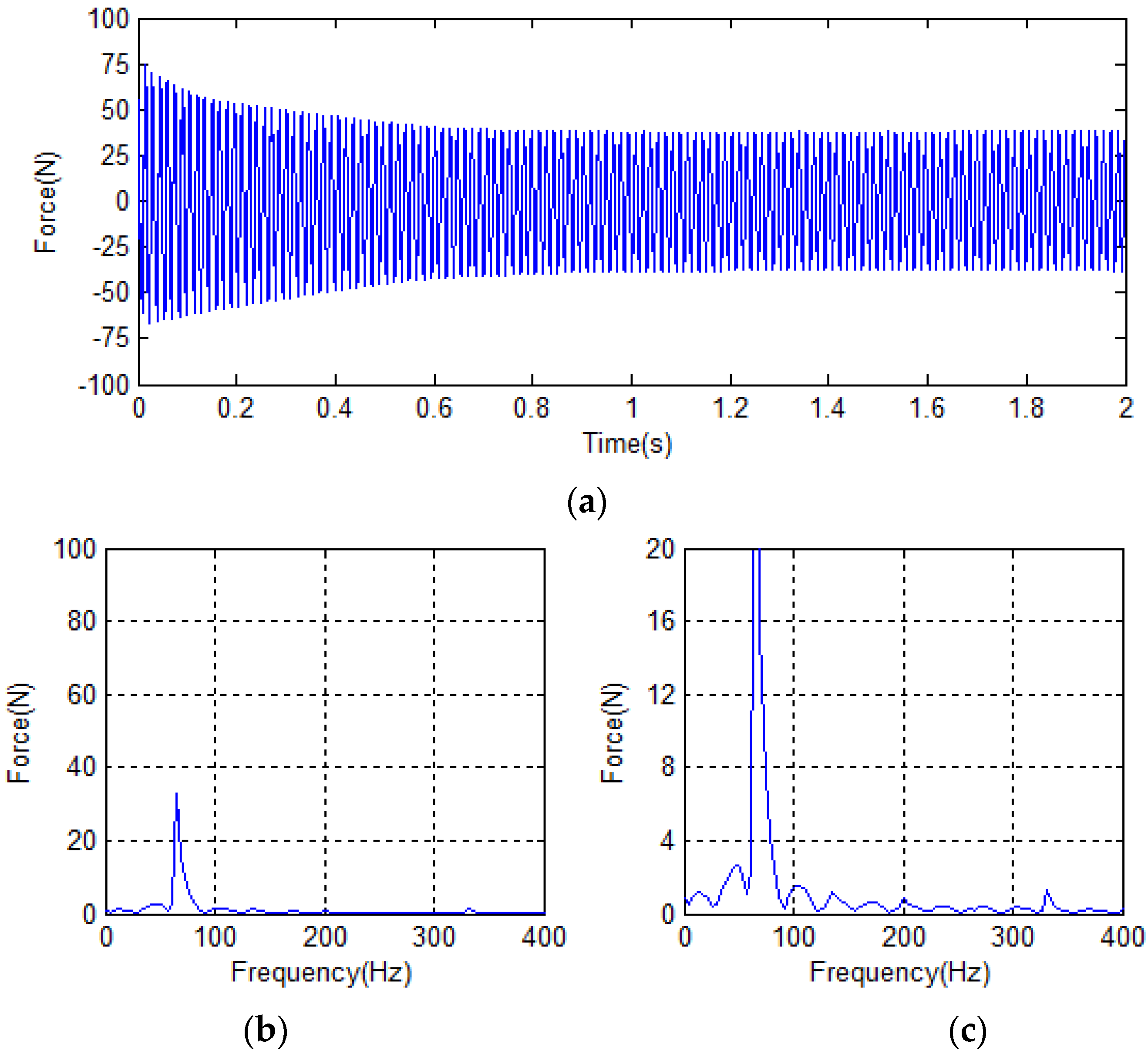
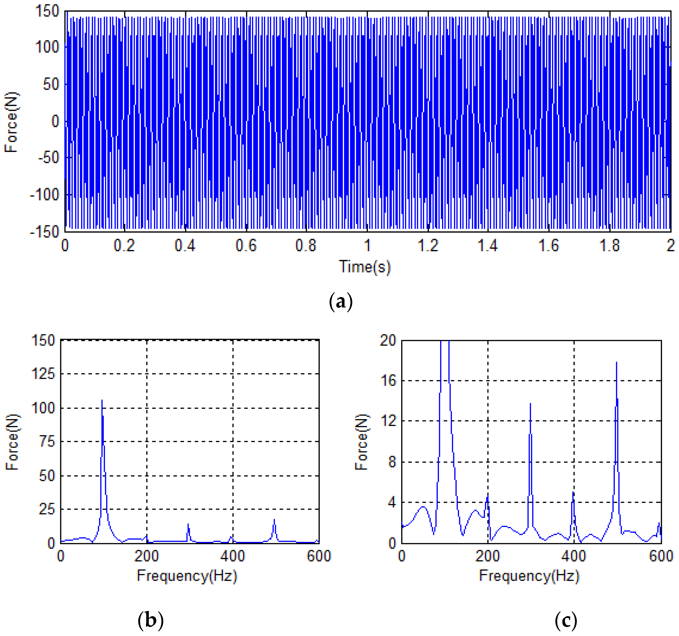
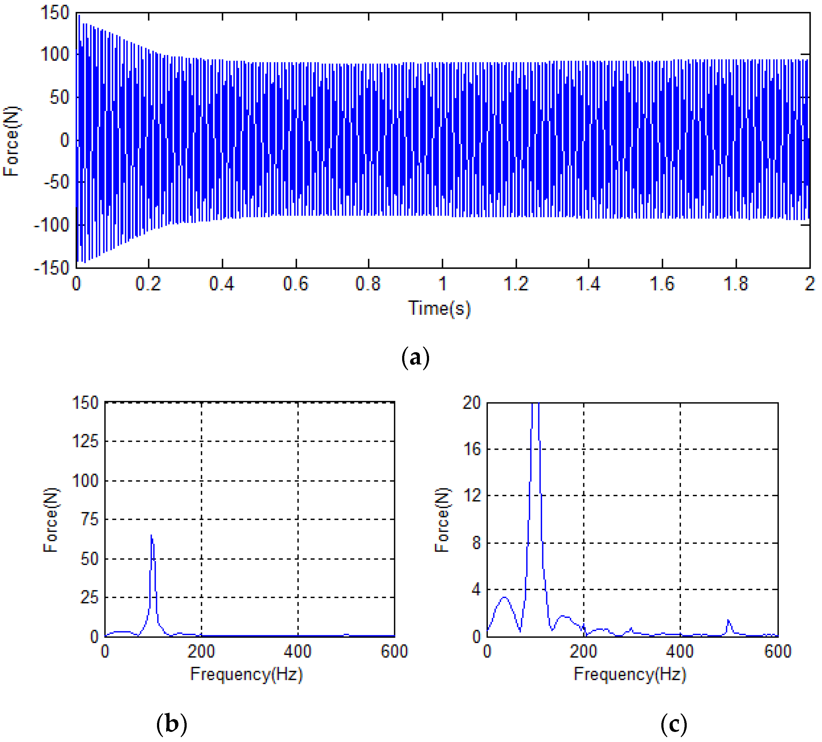
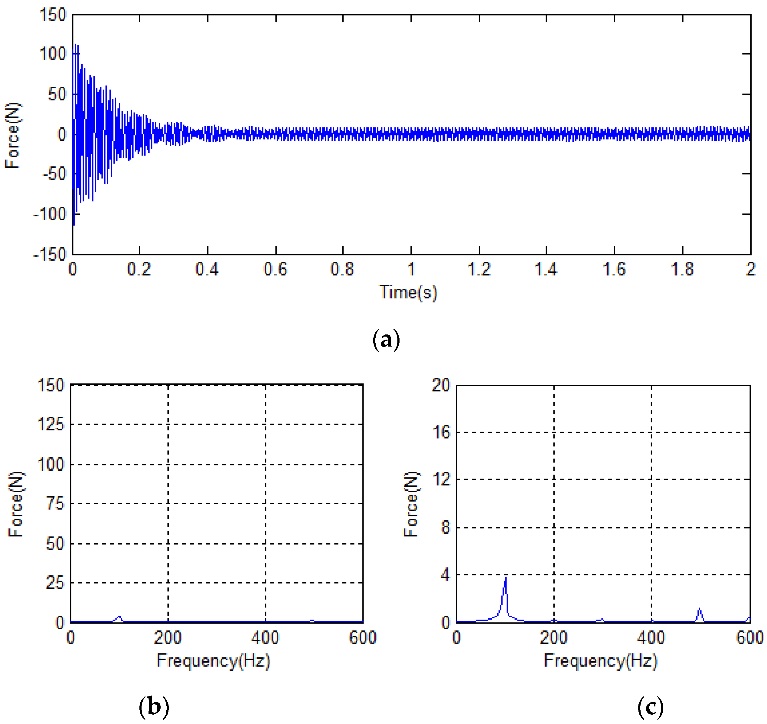
4.2. Analysis of Simulation Results

According to the above design parameters, simulation studies were carried out at different rotational speeds. The working speed of the flywheel is mainly between 418 rad/s and 628 rad/s, so the two speeds are simulated and analyzed.
When the rotational speed was 418 rad/s, the time domain diagram of the vibration force was as shown in Figure 10a, and the vibration amplitude was 74.7 N. Figure 10b shows that the amplitude of the same frequency force was 42.8 N, and the amplitude of the five-times frequency was 18.4 N.
The time domain diagram of the vibration force after the repetitive controller suppression is shown in Figure 11a. The vibration amplitude was reduced, the same frequency force was reduced to 32.7 N, and the two-times frequency vibration force was reduced from 4.7 to 1.5 N. The amplitudes of the three-, four-, and five-times frequency reduced from 9.5, 4.2, and 18.1 N to 0.6, 0.4, and 1.3 N, respectively. The frequency-doubling vibration force was effectively suppressed after the addition of the repetitive controller. At this time, the content of the vibration force was mainly the same frequency vibration force, the same frequency force produced by current was suppressed, but the displacement vibration force still exists, so it was important to compensate for the same frequency displacement vibration force.
The time domain diagram of the vibration force after the suppression of the compound control method is shown in Figure 12a. The amplitude of the vibration force was greatly reduced to 3.1 N at 0.6 s, and the amplitude of the same frequency was obviously reduced to 1.8 N, as shown in Figure 12c. At the same time, the amplitudes of two-, three-, four-, and five-times frequencies reduced to 0.1, 0.4, 0.2, and 1.1 N, respectively.
The time domain and frequency spectrum analysis when the rotational speed is 628 rad/s is shown in Figure 13. The same frequency vibration force caused by the mass imbalance is proportional to the square of the speed. Its amplitude increases rapidly to 102 N, and the frequency doubling quantity increases accordingly with the increase in speed. At this time, the vibration force of the five-times frequency increases to 18.5 N. The time domain and frequency spectrum analysis after adding the repetitive controller is shown in Figure 14, and the same frequency vibration force is reduced to 64.6 N (approximately 36.7%). The three-, four-, and five-times frequency vibration forces are reduced to 0.7, 0.3, and 1.1 N, respectively. This also shows the effectiveness of the repetitive controller in suppressing the electromagnetic force generated by each frequency-doubling current. The stability after 0.6 s of compound repetitive control is shown in Figure 15. The spectrum analysis shown in Figure 15c demonstrates that the vibration force of the same frequency is rapidly reduced to 3.8 N, and the amplitudes of other frequencies are also slightly reduced. After adding the compound suppression method, the amplitude of the vibration force is suppressed from 140.1 to approximately 7.3 N, and the suppression result is approximately 94.8% that of the unsuppressed method. This verifies the effectiveness of the method.

5. Conclusions

In this study, through the establishment of the interference model of the magnetic suspension flywheel, the mechanism of mass imbalance and sensor runout to produce the flywheel vibration force was analyzed. Based on the symmetry of the flywheel model, the x-direction was selected for the study, and a compound control method based on a repetitive controller and the same frequency-displacement stiffness force compensation was proposed. The parameters of the method were designed and the stability was analyzed. Simulation analysis of the magnetic suspension flywheel at different speeds was conducted. Compared with the repetitive controller, the vibration force of each frequency is correspondingly suppressed. When the rotating speeds were 418 and 628 rad/s, the suppression rate of the vibration force is nearly 95%, verifying the effectiveness of the compound control method for the suppression of each multiple-frequency vibration force. Future research will focus on the method to further improve the vibration suppression accuracy on the basis of considering the nonlinearity of the flywheel model.

Author Contributions

Conceptualization, Y.Z.; funding acquisition, K.L.; methodology, J.W.; supervision, Z.Z.; writing—original draft, Y.Z.; writing—review & editing, K.L., J.W. and Z.Z. All authors have read and agreed to the published version of the manuscript.

Funding

This research was funded by the Shenzhen Science and Technology Program (Grant No. JCYJ20200109142205924, 202001093000459).

Institutional Review Board Statement

Not applicable.

Informed Consent Statement

Not applicable.

Data Availability Statement

The data that support the findings of this study are available from the corresponding author upon reasonable request.

Conflicts of Interest

The authors declare no conflict of interest.

References

  1. Schweitzer, G.; Bleuler, H.; Maslen, E.H.; Cole, M.; Keogh, P.; Larsonneur, R.; Maslen, E.; Nordmann, R.; Okada, Y.; Schweitzer, G. Magnetic Bearings: Theory, Design, and Application to Rotating Machinery; Springer: Berlin/Heidelberg, Germany, 2009. [Google Scholar]
  2. Fang, J.C.; Xu, X.B.; Xie, J.J. Active vibration control of rotor imbalance in active magnetic bearing systems. J. Vib. Control. 2015, 21, 684–700. [Google Scholar] [CrossRef]
  3. Tang, J.; Xiang, B.; Zhang, Y. Dynamic characteristics of the rotor in a magnetically suspended control moment gyroscope with active magnetic bearing and passive magnetic bearing. ISA Trans. 2014, 53, 1357–1365. [Google Scholar] [CrossRef] [PubMed]
  4. Fang, J.; Zheng, S.; Han, B. Attitude Sensing and Dynamic Decoupling Based on Active Magnetic Bearing of MSDGCMG. IEEE Trans. Instrum. Meas. 2012, 61, 338–348. [Google Scholar] [CrossRef]
  5. Wang, H.; Liu, K.; Ao, P. Magnetic Field and Specific Axial Load Capacity of Hybrid Magnetic Bearing. IEEE T Magn. 2013, 49, 4911–4917. [Google Scholar] [CrossRef]
  6. Peng, C.; Fang, J.C.; Cui, P.L. Dynamics Modeling and Measurement of the Microvibrations for a Magnetically Suspended Flywheel. IEEE Trans. Instrum. Meas. 2015, 64, 3239–3252. [Google Scholar] [CrossRef]
  7. Setiawan, J.D.; Mukherjee, R.; Maslen, E.H. Adaptive compensation of sensor runout for magnetic bearings with uncertain parameters: Theory and experiments. J. Dyn. Syst.-T Asme. 2001, 123, 211–218. [Google Scholar] [CrossRef]
  8. Jiang, K.J.; Zhu, C.S.; Chen, L.L. Unbalance Compensation by Recursive Seeking Unbalance Mass Position in Active Magnetic Bearing-Rotor System. IEEE Trans. Ind. Electron. 2015, 62, 5655–5664. [Google Scholar] [CrossRef]
  9. Zhang, Y.; Liu, K.; Zhang, Z. Harmonic vibration suppression for magnetically suspended flywheel with rotor unbalance and sensor runout. AIP Adv. 2018, 8, 105207. [Google Scholar] [CrossRef] [Green Version]
  10. Zheng, Y.; Mo, N.; Zhou, Y.; Shi, Z. Unbalance Compensation and Automatic Balance of Active Magnetic Bearing Rotor System by Using Iterative Learning Control. IEEE Access 2019, 7, 122613–122625. [Google Scholar] [CrossRef]
  11. Qiao, X.L.; Hu, G.J. Active Control for Multinode Unbalanced Vibration of Flexible Spindle Rotor System with Active Magnetic Bearing. Shock. Vib. 2017, 2017, 9706493. [Google Scholar] [CrossRef] [Green Version]
  12. Gao, H.; Xu, L.X. Real-time vibration compensation for active magnetic bearing systems based on LMS algorithm. J. Vib. Eng. 2009, 22, 583–588. [Google Scholar]
  13. Herzog, R.; Buhler, P.; Gahler, C.; Larsonneur, R. Unbalance compensation using generalized notch filters in the multivariable feedback of magnetic bearings. IEEE T Contr. Syst. T 1996, 4, 580–586. [Google Scholar] [CrossRef]
  14. Zheng, S.; Chen, Q.; Ren, H. Active Balancing Control of AMB-Rotor Systems Using a Phase-Shift Notch Filter Connected in Parallel Mode. IEEE Trans. Ind. Electron. 2016, 63, 3777–3785. [Google Scholar] [CrossRef]
  15. Peng, C.; Fan, Y.; Huang, Z.; Han, B.; Fang, J. Frequency-varying synchronous micro-vibration suppression for a MSFW with application of small-gain theorem. Mech. Syst. Signal. Pr. 2017, 82, 432–447. [Google Scholar] [CrossRef]
  16. Xu, X.; Fang, J.; Li, H.; Cui, P. Active suppression of imbalance vibration in the magnetically suspended control moment gyro. J. Vib. Control 2013, 21, 989–1003. [Google Scholar] [CrossRef]
  17. Chen, Q.; Liu, G.; Zheng, S. Suppression of imbalance vibration for AMBs controlled driveline system using double-loop structure. J. Sound Vib. 2015, 337, 1–13. [Google Scholar] [CrossRef]
  18. Chen, Q.; Liu, G.; Han, B. Unbalance vibration suppression for AMBs system using adaptive notch filter. Mech. Syst. Signal. Pr. 2017, 93, 136–150. [Google Scholar] [CrossRef]
  19. Peng, C.; Zhu, M.; Wang, K.; Ren, Y.; Deng, Z. A Two-Stage Synchronous Vibration Control for Magnetically Suspended Rotor System in the Full Speed Range. IEEE Trans. Ind. Electron. 2020, 67, 480–489. [Google Scholar] [CrossRef]
  20. Setiawan, J.D.; Mukherjee, R.; Maslen, E.H. Synchronous Sensor Runout and Unbalance Compensation in Active Magnetic Bearings Using Bias Current Excitation. J. Dyn. Syst. Meas. Control 2002, 124, 14–24. [Google Scholar] [CrossRef]
  21. Cui, P.L.; Li, S.; Wang, Q.R.; Gao, Q.; Cui, J.; Zhang, H.J. Harmonic Current Suppression of an AMB Rotor System at Variable Rotation Speed Based on Multiple Phase-Shift Notch Filters. IEEE Trans. Ind. Electron. 2016, 63, 6962–6969. [Google Scholar] [CrossRef]
  22. Zhou, K.L.; Wang, D.W.; Zhang, B.; Wang, Y.G. Plug-In Dual-Mode-Structure Repetitive Controller for CVCF PWM Inverters. IEEE Trans. Ind. Electron. 2009, 56, 784–791. [Google Scholar] [CrossRef]
  23. Han, B.; Lee, J.S.; Kim, M. Repetitive Controller With Phase-Lead Compensation for Cuk CCM Inverter. IEEE Trans. Ind. Electron. 2018, 65, 2356–2367. [Google Scholar] [CrossRef]
  24. Xu, X.B.; Fang, J.C.; Liu, G.; Zhang, H.J. Model development and harmonic current reduction in active magnetic bearing systems with rotor imbalance and sensor runout. J. Vib. Control 2015, 21, 2520–2535. [Google Scholar] [CrossRef]
  25. Cui, P.; Li, S.; Zhao, G.; Peng, C. Suppression of Harmonic Current in Active–Passive Magnetically Suspended CMG Using Improved Repetitive Controller. IEEE/ASME Trans. Mechatron. 2016, 21, 2132–2141. [Google Scholar] [CrossRef]
  26. Cui, P.; Zhang, G. Modified Repetitive Control for Odd Harmonic Current Suppression in Magnetically Suspended Rotor Systems. IEEE Trans. Ind. Electron. 2018, 66, 8008–8018. [Google Scholar] [CrossRef]
  27. Cui, P.; Zhang, G.; Liu, Z.; Xu, H. Quasi-Resonant Control for Harmonic Current Suppression of a Magnetically Suspended Rotor. IEEE T Power Electr. 2019, 34, 4937–4950. [Google Scholar] [CrossRef]
  28. Cui, P.L.; Wang, Q.R.; Zhang, G.X.; Gao, Q. Hybrid Fractional Repetitive Control for Magnetically Suspended Rotor Systems. IEEE Trans. Ind. Electron. 2018, 65, 3491–3498. [Google Scholar] [CrossRef]
  29. Li, J.; Liu, G.; Cui, P.; Zheng, S.; Chen, X. 3/2-Order Dual-Mode Fractional Repetitive Control for Harmonic Vibration Suppression in Magnetically Suspended Rotor. IEEE Sens. J. 2020, 20, 14713–14721. [Google Scholar] [CrossRef]
  30. Srinivasan, K.; Shaw, F.R. Analysis and Design of Repetitive Control Systems using the Regeneration Spectrum. In Proceedings of the 1990 American Control Conference, San Diego, CA, USA, 23–25 May 1990. [Google Scholar]
Figure 1. Structure of magnetically suspended flywheel.
Symmetry 14 00949 g001
Figure 2. Block diagram of x-direction.
Symmetry 14 00949 g002
Figure 3. Block diagram of the system with compound method.
Symmetry 14 00949 g003
Figure 4. Equivalent control block diagram of the compound control method.
Symmetry 14 00949 g004
Figure 5. Block diagram of G r c ( s ) with e T 1 s .
Symmetry 14 00949 g005
Figure 6. Phase diagram of S 0 ( s ) , G f ( s ) S 0 ( s ) .
Symmetry 14 00949 g006
Figure 7. Phase diagram of F ( s ) with different N.
Symmetry 14 00949 g007
Figure 8. Magnitude diagram of F ( s ) .
Symmetry 14 00949 g008
Figure 9. Phase diagram of S 1 ( s ) .
Symmetry 14 00949 g009
Figure 10. Rotational speed at 418 rad/s without the suppression method: (a) time domain diagram, (b) spectrum diagram, and (c) detailed spectrum diagram.
Symmetry 14 00949 g010
Figure 11. Rotational speed at 418 rad/s with repetitive control method: (a) time domain diagram, (b) spectrum diagram, and (c) detailed spectrum diagram.
Symmetry 14 00949 g011
Figure 12. Rotational speed at 418 rad/s with compound control method: (a) time domain diagram, (b) spectrum diagram, and (c) detailed spectrum diagram.
Symmetry 14 00949 g012
Figure 13. Rotational speed at 628 rad/s without the suppression method: (a) time domain diagram, (b) spectrum diagram, and (c) detailed spectrum diagram.
Symmetry 14 00949 g013
Figure 14. Rotational speed at 628 rad/s with repetitive control method: (a) time domain diagram, (b) spectrum diagram, and (c) detailed spectrum diagram.
Symmetry 14 00949 g014
Figure 15. Rotational speed at 628 rad/s with compound control method: (a) time domain diagram, (b) spectrum diagram, and (c) detailed spectrum diagram.
Symmetry 14 00949 g015
Table 1. Parameters of magnetically suspended flywheel.
SymbolParametersValueSymbolParametersValue
mRotor mass4.8 kg τ l Low pass coefficient0.0001
KiCurrent stiffness coefficient125 N/AKhDisplacement stiffness coefficient50,000 N/m
KwAmplifier gain0.00004 A/VNDifferentiator depth coefficient10,000
τ w Amplifier time coefficient0.0005KpProportional coefficient3
KsSensor coefficient8000 V/mKiIntegration coefficient0.1
KadSample gain3276.8 V − 1KdDifferential coefficient0.012
Table 2. Parameters of unbalance and sensor runout.
SymbolParametersValueInitial Angle
eUnbalance coefficient50 π /6
e s r 1 First sensor runout coefficient2 2 π /5
e s r 2 Second sensor runout coefficient2.2 π /3
e s r 3 Third sensor runout coefficient5 π /8
e s r 4 Forth sensor runout coefficient2 π /4
e s r 5 Fifth sensor runout coefficient8 π /7
Publisher’s Note: MDPI stays neutral with regard to jurisdictional claims in published maps and institutional affiliations.

