Article

Estimation of the FST-Layering Time for Shock Ignition ICF Targets

by
Irina Aleksandrova
and
Elena Koresheva
*
P.N. Lebedev Physical Institute of RAS, Moscow 119991, Russia
*
Author to whom correspondence should be addressed.
Symmetry 2022, 14(7), 1322; https://doi.org/10.3390/sym14071322
Submission received: 15 March 2022 / Revised: 15 June 2022 / Accepted: 24 June 2022 / Published: 26 June 2022

Abstract

:
The challenge in the field of inertial confinement fusion (ICF) research is related to the study of alternative schemes for fuel ignition on laser systems of medium and megajoule scales. At the moment, it is considered promising to use the method of shock ignition of fuel in a pre-compressed cryogenic target using a focused shock wave (shock- or self-ignition (SI) mode). To confirm the applicability of this scheme to ICF, it is necessary to develop technologies for mass-fabrication of the corresponding targets with a spherically symmetric cryogenic layer (hereinafter referred to as SI-targets). These targets have a low initial aspect ratio Acl (Acl = 3 and Acl = 5) because they are expected to be more hydrodynamically stable during implosion. The paper discusses the preparation of SI-targets for laser experiments using the free-standing target (FST) layering method developed at the Lebedev Physical Institute (LPI). It is shown that, based on FST, it is possible to build a prototype layering module for in-line production of free-standing SI-targets, and the layering time, τform, does not exceed 30 s both for deuterium and deuterium-tritium fuel. Very short values of τform make it possible to obtain layers with a stable isotropic fuel structure to meet the requirements of implosion physics.

1. Introduction

The objective of this article is to expand the FST-layering method developed at the LPI on SI-target fabrication. A schematic representation of the FST-layering method is shown in Figure 1a,c, where the following designations are used: layering module (LM), shell container (SC), layering channel (LC), test chamber (TC). The SI-targets include a polymer shell and a cryogenic fuel layer (Figure 1b).
The SI-target specifications are given in Table 1, where the following symbols are accepted: R and R0 are the outer and inner radii of the shell, ΔR is its thickness, Rvapor is the radius of the gas cavity (contains saturated fuel vapor), W = R0—Rvapor is the thickness of the cryogenic layer, Acl is the initial aspect ratio of the cryogenic layer (Acl = Rvapor/W). For low-aspect SI-targets, Acl is in the range of 3–5 [1,2].
The FST-layering method works with free-standing (or unmounted) and line-moving targets and allows one to fabricate large quantities of such targets and continuously inject them at the laser focus [3]. The FST-layering method is highly compatible with a new approach to the target delivery system based on noncontact target transport with levitation [4] which is a necessary condition for high-repetition-rate laser facilities. Below, we evaluate the prospects of the FST-layering method for in-line production of the SI-targets.
The algorithm for conducting the FST-layering experiments is implemented as follows:
(1)
The process starts with the ramp filling of a batch of unmounted shells located in the shell container with fuel gas at room temperature (300 K) and transporting them at the same temperature from the filling system to the layering module. In order to obtain a thick cryogenic layer (Table 1, W = 198 − 147 μm), the shells are filled to a high internal pressures Pf with deuterium (D2) and deuterium-tritium mixture (DT). The filling stage for SI-targets was studied in detail in [5] where we presented the results of modeling the D2/DT-fill time and rates for SI-targets. It was found that the fill pressures were Pf = 678–1250 atm for D2 and Pf = 690–1230 atm for DT. When implementing the optimal filling procedure with a constant pressure gradient, the calculations showed that, on average, the SI-targets can be filled to the required pressures in a time from 1.65 h (polyimide) to 7 h (polystyrene) with Young’s modulus E = 3 GPa and a safety factor δ = 0.55 (i.e., with half the pressure drop across the shell wall relative to the maximum allowable value). As the value of δ increases, the filling time is even shorter.
(2)
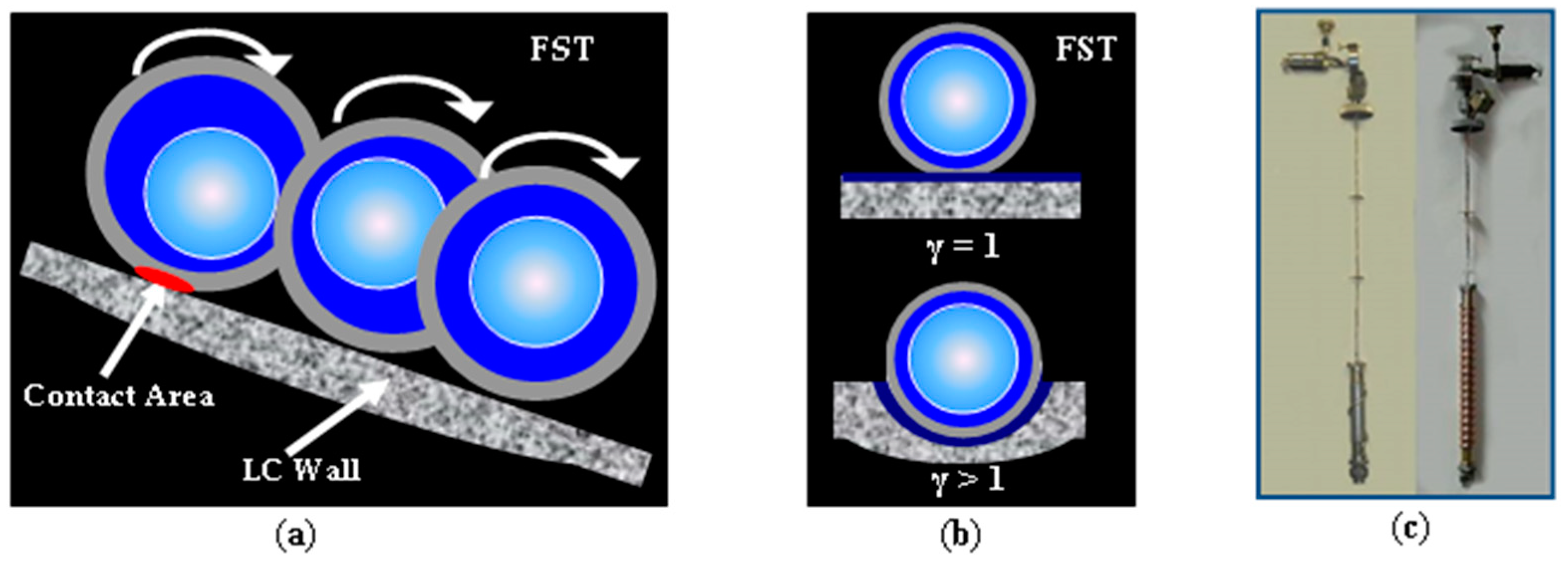
The next stage includes mounting the shell container in the layering module, followed by its cooling to the depressurization temperature Td, which is significantly lower than room temperature. The depressurization procedure is necessary to drop the pressure in the shell container and remove the fuel outside the shells. Taking into account that the fill pressure Pf is very high (as mentioned above), it is necessary to determine the conditions that exclude both the shell damage by internal pressure and the fuel leakage from the shells due to back diffusion. The fulfilment of these conditions is possible only at the temperature decrease, when the gas pressure drops down, the gas permeability decreases, and the strength of the shell material increases. We have found that for polystyrene shells with a tensile strength σ < 50 MPa, the required pressure reduction for a safe depressurization of the shell container (considering both D2 and DT) can be achieved only by liquefying the fuel inside it, i.e., for Td < Tcp (Tcp is the critical point temperature). A gravitationally sagged liquid remains in the shells, and this is an initial fuel state before the FST-layering (Figure 1c, at the top). For stronger shells (σ ~ 110 MPa), the depressurization temperature can reach the values Td = 45 K > Tcp, i.e., the value of σ is sufficient to depressurize the shell container when the fuel is gaseous (it can be, for example, for polyimide and glow discharge polymer).
(3)
The final step is freezing the spherically symmetric layer in the shells during their rolling inside the spiral layering channel, i.e., the fabrication of the cryogenic target itself (Figure 1c, at the bottom). It is to this stage that this work will be devoted.

2. Mathematical Modeling of the SI-Target Fabrication by the FST-Layering Method

Fabrication of a solid fuel layer in the batch of moving shells by the FST-layering method is carried out during the shells’ transport by injection between the main functional elements of the FST-layering module: SC—LC—TC (Figure 1a). The layering channel is made from a metal hollow tube cooled outside by liquid helium. The optical test chamber is used to characterize the finished cryogenic targets, and also serves as an intermediate unit between the FST-layering module and the target injector.
During the FST-layering, two processes are mostly responsible for maintaining a spherically symmetric layer formation (Figure 2):
A random target rotation when it is rolling down along the layering channel (single, double, or triple spirals) results in a liquid layer symmetrization (Figure 2a).
A heat transport outside the target via conduction through a small contact area between the shell wall and the layering channel wall results in a liquid layer freezing (Figure 2a,b).
Below we evaluate the prospects of the FST-layering method for in-line SI-target production. The main parameter to be determined is the layering time (τform) during which a cryogenic layer is formed inside the shell as it moves in the spiral layering channel (Figure 2c). Therefore, simulation of the FST-layering process is necessary for FST-layering module construction to produce spherical cryogenic targets for their shock ignition in laser thermonuclear fusion.
In [6], a model of rapid fuel freezing inside moving free-standing shells was proposed and further adapted for different classes of targets. This model is based on the solution of a Stefan problem [7] related to phase transitions in matter, in which the boundary between the phases can move with time. It is assumed that all three fuel phases can coexist inside the shell, whereas the real number of phases is determined by the thermal target history during the FST-layering process. The thermal conductivity and heat capacity of the fuel are assumed to be known and determined by interpolation of existing experimental data [8,9,10]. The densities of the liquid and solid phases as a function of temperature, ρliquid and ρsolid, are also known from [8,9,10]. The boundary condition on the outer shell surface describes the heat removal from the target. In our case, the cooling rates are realized when the target is cooled by heat conduction through a small contact area between the shell and the layering channel wall (Figure 2a,b), i.e., the heat is removed when only a part of the shell is in thermal contact with the layering channel.
The contact area, Sca, occurs due to the shell deformation during its motion in the layering channel. An estimate of Sca depending on the target characteristics can be found in [6], where the geometrical contact area is determined by the following relationship:
χg = Sca/Ssh = (½)(3N/(πR2targetδshE))1/2, δsh = Ash−1,
where χg is the dimensionless parameter, Ssh is the shell surface, E is the Young’s modulus of the shell, N is the normal reaction of support of the layering channel wall (Figure 2a). The expansion of Sca due to the LC curvature can be taken into account using the coefficient γ [11]:
γ = 1/(1 − Rtarget/Rtube)1/3,
where Rtube is the radius of the hollow metal tube from which the layering channel is made (Figure 2b).
Note that a major influence on the Sca expansion is conditioned by the heat transfer along the shell surface under the heat exchange with fuel. This is related to the thermal conductivity, λ, of the hydrogen isotopes, which is much greater than that of the shell (in our case, polystyrene). Indeed, the value of λ of polystyrene varies from 0.029 W/mK at 4.2 K to 0.074 at 20 K [12]; for D2 λ = 0.46 W/mK at 4.2 K and 0.27 W/mK at the triple point temperature Ttp = 18.7 K; for DT λ = 0.54 W/mK at 6 K and 0.24 W/mK at Ttp = 19.7 K [8,9,10]. These data indicate that the tangential heat flows cannot be neglected. Modeling and taking into account the tangential and radial heat flows made it possible to obtain an accurate estimate of the Sca expansion: it is almost an order of magnitude greater than the geometrical contact area [3]. This leads to a significant increase in the real values of Sca and, as a consequence, to the formation of the so-called effective contact area characterized by the parameter χeff.
In a general case, the value of χeff depends on the material and composition of the target, as well as on the course of target cooling. Summarizing the above, we will have:
χeff = (ξγ/2) · (3G/(πR2targetδshE))1/2,
where ξ is the thermal factor of the Sca expansion.
The process of the target cooling is an isochoric process shown in Figure 3a, in which the following nomenclature is accepted: Tcp is the critical point (CP) temperature, Ttp is the triple point (TP) temperature, and Ts is the temperature of starting the separation process into liquid and gaseous phases. The entire process can be conventionally divided into four stages:
  • Target cooling from T = 300 K to the temperature Td. This stage is important for the shell container depressurization.
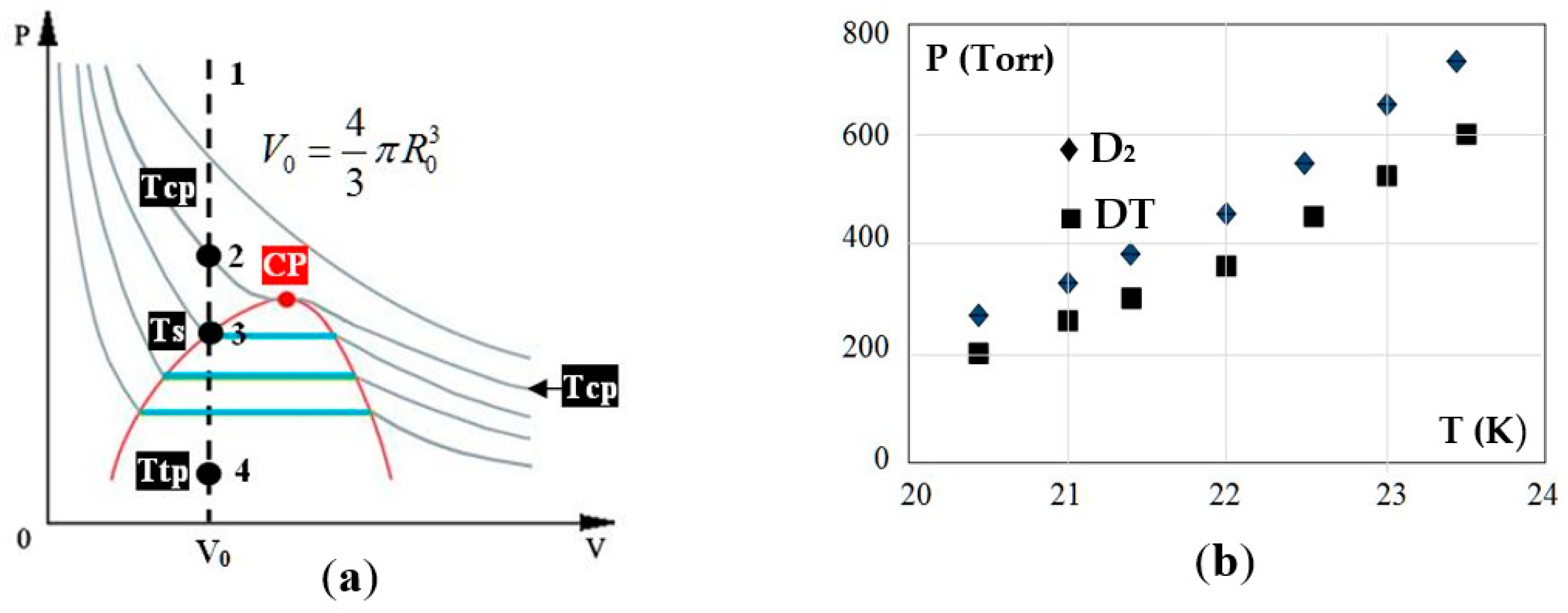
  • Target cooling from Td to the temperature Tin, which corresponds to the target entry into the layering channel (Tin is an initial target temperature before the FST-layering). The value of Tin can be between Ts and Ttp, i.e., there is already a certain amount of liquid fuel inside the shell (Figure 1c, at the top).
  • Formation and cooling of the liquid phase in the temperature range of TinTtp. The value of Tin determines one of the key parameters—the time of liquid phase existence, τliquid, which must be sufficient (~35–40% of τform) to symmetrize the liquid layer when the shells are rolling along the layering channel [3]. Note that as they cool down, the role of fuel vapor becomes negligible (Figure 3b). In the triple point its pressure is ~0.2 atm for all hydrogen isotopes [8,9,10].
  • Liquid phase freezing at the triple point temperature Ttp.
  • If necessary, cooling the target from Ttp to a certain operating temperature Tform.
For computation of the FST-layering time, it is necessary to know the SI-target parameters in the two-phase state of “Ice + Vapor” (Figure 1b) at a temperature Tform. According to [1,2] they have the following values:
DT fuel: Tform = 18.3 K, vapor density ρvapor = 0.3 mg/cm3, ice density ρsolid = 250 mg/cm3;
D2 fuel: Tform = Ttp = 18.7 K, vapor density ρvapor = 0.448 mg/cm3, ice density ρsolid = 196.687 mg/cm3.
This allows one to calculate the fuel mass parameters, i.e., those initial data that will determine the course of the FST-layering process, namely: msolid—solid fuel mass, mνapor—fuel vapor mass; ρfill—gaseous fuel density in the shell at 300 K, Mfuel—total mass of fuel. The obtained results are shown in Table 2.
Another key factor is related to the fact that the quantitative ratio between the liquid and gaseous components of fuel changes with a temperature drop, which plays an important role in determining the dynamics of the relative radius of the gas cavity. In the two-phase region (T < Ts), the masses of gas (this is saturated vapor) and liquid are equal, respectively:
mvapor = (4/3) π (R0W)3 · ρvapor(T),
mliquid = (4/3) π · (R03 − (R0W)3) · ρliquid(T),
where the thickness of the liquid layer is found from the law of conservation of mass:
Mfuel = mvapour + mliquid,
Mfuel = (4/3) π · R03 · ρfill,
or
(1 − W/R0)3 · ρvapor(T) + (1 − (1 − W/R0)3) · ρliquid(T) = ρfill.
Here, T is the target temperature, and the phase densities ρvapor and ρliquid are known from the phase diagram [8,9,10].
Assuming R0W = Rvapor is the radius of the gas cavity (Figure 1b) we have:
(1 − W/R0)3 = R3vapor(T)/R03 = (ρliquid(T) − ρfill)/(ρliquid(T) − ρvapor(T)).
Let us introduce the following parameter
α (ρfill,T) = (ρliquid(T) − ρfill)/(ρliquid(T) − ρvapor(T))
and write the value of ρfill as
Θ = ρfill/ρcp,
where ρcp is the critical density (ρcp = 69.8 mg/cm3 for D2, and ρcp = 87.06 mg/cm3 for DT). Then the parameter α can be written in the form:
α (ρfill,T) = (ρliquid(T) − Θρcp)/(ρliquid(T) − ρvapor(T)).
From equalities (1)–(4), taking into account (7), it is easy to obtain a number of useful relations:
(Vvapor(T)/V0) = α, Rvapor(T)/R0 = α1/3, (Vliquid(T)/V0) = 1 − α
mliquid(T)/mfuel = (ρliquid(T)/ρfill)(1 − α), mvapor(T)/mfuel = (ρvapor(T)/ρfill) · α
Acl = 1/(1 − α1/3).
Note that if the target temperature is below the triple point temperature, then there is already a solid cryogenic layer inside the shell. Relationships (1–10) remain valid in this case as well, with the replacement of the index “liquid” by “solid”.
To select the temperature Tin we use relation (8) for α1/3, which determines the dynamics of the relative radius Rvapor/R0 = α1/3 during the target cooling. Figure 4 shows the calculated data for Rvapor/R0 = α1/3 in the case of deuterium. For SI-targets the parameter ϴ (see formula (6)) is equal to ϴ1 = 1.1, ϴ2 = 1.19, ϴ3 = 1.63 so that the range Δϴ = 1.0–1.63 covers all three SI-targets (see Figure 4).
From Figure 4 it is clearly seen that starting from T = 30 K the function Rvapor/R0 = α1/3 is almost linear, which is extremely important for the process of fuel layer symmetrization (see Figure 2).
Let us make a few remarks regarding the choice of the shell material. Analyzing the filling stage for the SI-targets [5] we considered three different shell materials: polyimide, polystyrene and glow discharged polymer (GDP). However, analyzing the FST-layering stage, a necessary set of shell parameters (tabulated data on heat capacity and thermal conductivity at cryogenic temperatures, see Table 3 [12]) is available only for polystyrene (PS). For this reason, computation of the layering time was made for two options: “PS ― D2” and “PS ― DT”. The results of calculations for two values of Tin are presented in Table 4.
The main conclusion is as follows: the FST-layering time for all three designs of SI-targets does not exceed 30 s for both D2 and DT fuel. This is of great importance for reducing the time and space scales of all production steps in the target fabrication facilities. In addition, the lifetime of the liquid phase at Tin = 30 K is ~60% for D2 and ~63% for DT, and at Tin = 26 K it is ~41% and ~46%, respectively, which is a sufficient condition for the symmetrization of the fuel layer.

3. Discussion of the Obtained Results

In this section, we will discuss the obtained results in terms of constructing a prototype of the FST-layering module for the layering times shown in Table 4. Indeed, the question of the layering channel geometry in which the SI-targets can be fabricated remains open. A key issue is the spiral type (n-fold spirals, n = 1, 2, 3) and its parameters (inclination angle, diameter, height and width of the spiral). These values directly control the target residence time in the layering channel, τres, which must be longer than the layering time, namely: τformτres. By varying the above parameters, one can optimize the FST-layering method for any target class, including SI-targets.
Generally, one can view the target motion in the following rolling conditions:
Target slides on the layering channel surface (no rotation: sliding and only sliding or pure S&S-mode);
Target combines rolling with sliding (rolling with sliding or mixed R&S-mode);
Target rolls on the layering channel surface without sliding (rolling and only rolling or pure R&R-mode).
During target fabrication it is necessary to realize only the R&R-mode to avoid the outer shell roughening and to achieve fuel layer uniformity. Therefore, the time-integral performance criterion can be written in the following type (τrol is the time of pure target rolling):
τform ≤ τres = τrol
Thus, determination of the rolling conditions is one of the main problems, which influences the choice of the layering module operation including simplifying the physics design and modifying the specifications. First of all, we should to determine the spiral angles β for realizing the pure target rolling (R&R-mode).
In [13], calculations were performed for two versions of the layering channels (double and triple spirals), which were fabricated and tested just in R&R-mode for two spiral angles β = 11.5° and β = 16.7°.
For SI-targets, we start with a layering channel in the form of a double spiral. Its parameters are: spiral angle β = 11.5°, radius of each spiral Rcyl = 21 mm, height of each spiral Hcyl = 450 mm, τrol = 23.5 s for PS-shell with a diameter of ~2 mm, which corresponds to the SI-target dimensions (see Table 1). In other words, this 2S-LC can be used to carry out the FST-layering experiments at Tin = 26 K, since the main condition for SI-targets is met: τform < 22 s < τrol = 23.5 s (see Table 4).
Consider now the layering channel in the form of a triple spiral. Its parameters are: β = 16.7°, Rcyl = 21 mm, Hcyl = 880 mm, τrol ~ 35 s. In this case, the FST-layering experiments can be carried out both at Tin = 26 K and Tin = 30 K (see Table 4). The latter is extremely important, since the value of τliquid increases with an increase in the temperature Tin from 26 K to 30 K.
Thus, the modeling results have shown the benefits of the FST-layering method to develop and validate rapid layering technologies that are applicable to mass SI-target fabrication. This is due to the fact that:
The FST-layering method works with free-standing and line-moving targets. A specific future here is the possibility to build a prototype of the FST-layering module, which must be integrated in an FST-production line operating in high-repetition-rate conditions [3,4]. In [13], the key elements of the FST-production line and their functional description are given in detail. Additionally, the development strategy of such line creation seeking to develop commercial power production based on laser IFE has been discussed.
A short layering time (τform < 30 s for D2 and DT) is required to induce the formation of multiple crystals of different orientations for obtaining ultra-fine fuel layers with a stable isotropic fine-grained or nanocrystalline structure and avoiding instabilities caused by grain-affected shock velocity variations. A Fourier-spectrum of the bright band of the cryogenic layer is given in [14]. It has shown that surface imperfections of the cryogenic layer formed by the FST-layering are less than 0.15 microns for modes Nf = 20–30. Note also that under granularity growth (in which the grain size decreases) the material strength increases. This means that the ultra-fine fuel layers have an adequate thermal and mechanical stability which supports the fuel layer survivability under target injection and transport through the reaction chamber. Additionally, such short layering times are also promising in terms of tritium inventory reduction in the target fabrication facilities [15].
Recall that a conventional approach such as beta-layering uses with a single target and requires more than 17 h [16] for its fabrication with an aniisotropic layer such as a single crystal. A long-run beta-layering process in very strict isothermal conditions (target temperature must be controlled down to 1 mK precision) leads to the roughening of the layer surface and the provoking of implosion instabilities in the case of deviation from the specified conditions. Another important issue is related to the fact that each target must be mounted on a special suspension which excludes the target positioning at the laser focus by injection. Note that target injection is a necessary condition for achieving a high symmetry of irradiation by a laser, as well as plasma generation with an intensive thermonuclear reaction in high-repetition-rate laser facilities.

4. Conclusions

Shock ignition is a recently proposed ICF scheme, in which the stages of compression and hot spot formation are partly separated. An SI-target is composed of D2/DT gas surrounded by a cryogenic D2/DT solid layer as a fusion fuel. A distinctive feature of the design of these targets is a low initial aspect ratio (inner fuel layer radius/fuel layer thickness, Acl = 3 and Acl = 5-design) to provide greater implosion stability. The paper discusses the issues of SI-target fabrication using the FST-layering method. It has been shown that on this basis it is possible to build a prototype of the FST-layering module, operating with a batch of moving free-standing SI-targets under high-repetition-rate conditions. The layering time does not exceed 30 s for both D2 and DT, which offers the potential for obtaining an isotropic fuel that is very important for the progress towards ignition.

Author Contributions

Conceptualization, I.A. and E.K.; methodology and software, I.A.; investigation, I.A. and E.K.; data curation, E.K.; writing—original draft preparation, I.A.; writing—review and editing, E.K.; project administration, Elena Koresheva. All authors have read and agreed to the published version of the manuscript.

Funding

This research was funded by IAEA in the frame of the RC # 24154, as well as by the Government of Russia within the framework of the LPI State Task.

Institutional Review Board Statement

Not applicable.

Informed Consent Statement

Not applicable.

Data Availability Statement

Not applicable.

Conflicts of Interest

The authors declare no conflict of interest.

References

  1. Brandon, V.; Canaud, B.; Temporal, M.; Ramis, R. Low initial aspect-ratio direct-drive target designs for shock- or self-ignition in the context of the laser Megajoule. Nucl. Fusion 2014, 54, 083016. [Google Scholar] [CrossRef] [Green Version]
  2. Shang, W.L.; Betti, R.; Hu, S.X.; Woo, K.; Hao, L.; Ren, C.; Christopherson, A.R.; Bose, A.; Theobald, W. Electron shock ignition of inertial fusion targets. Phys. Rev. Lett. 2017, 119, 195001. [Google Scholar] [CrossRef] [PubMed] [Green Version]
  3. Aleksandrova, I.V.; Koresheva, E.R. Review on high repetition rate and mass production of the cryogenic targets for laser IFE. High Power Laser Sci. Eng. 2017, 5, e11. [Google Scholar] [CrossRef] [Green Version]
  4. Aleksandrova, I.V.; Koresheva, E.R.; Koshelev, E.L. A High-Pinning-Type-II Superconducting Maglev for ICF Target Delivery: Main principles, material options and demonstration models. High Power Lasers Sci. Eng. 2022, 10, 1–24. [Google Scholar] [CrossRef]
  5. Aleksandrova, I.V.; Koresheva, E.R. Cryogenic targets for shock ignition: Modeling of diffusion filling with a hydrogen fuel. Probl. At. Sci. Technol. Ser. Thermonucl. Fusion 2021, 44, 94–106. (in Russian). [Google Scholar] [CrossRef]
  6. Aleksandrova, I.V.; Bazdenkov, S.V.; Chtcherbakov, V.I. Rapid fuel layering inside moving free-standing ICF targets: Modeling results. Laser Part. Beams 2002, 20, 13–21. [Google Scholar] [CrossRef]
  7. Tikhonov, A.N.; Samarskiy, A.A. Equations of Mathematical Physics; Nauka: Moscow, Russia, 1977; p. 728. [Google Scholar]
  8. Roder, H.M.; Childs, G.E.; McCarthy, R.D.; Angerhofer, P.E. Survey of the Properties of the Hydrogen Isotopes below Their Critical Temperature; NBS Technical Note 641; US Government Printing Office: Washington, DC, USA, 1973; p. 132.
  9. Souers, P.C. Hydrogen Properties for Fusion Energy; University of California Press: London, UK, 1986; p. 391. [Google Scholar]
  10. Kucheev, S.O.; Hamza, A.V. Condensed Hydrogen for Thermonuclear Fusion. J. Appl. Phys. 2010, 108, 091101. [Google Scholar] [CrossRef]
  11. Landau, L.D.; Lifshits, E.M. Theoretical Physics, Theory of Elasticity, 4th ed.; Nauka: Moscow, Russia, 1987; p. 248. [Google Scholar]
  12. Malkov, M.P.; Danilov, I.B.; Zeldovich, A.G.; Fradkov, A.B. Handbook on physical and technical bases of cryogenics; Energy: Moscow, Russia, 1973; p. 392. [Google Scholar]
  13. Aleksandrova, I.V.; Koshelev, E.L.; Koresheva, E.L. In-line target production for laser IFE. Appl. Sci. 2020, 10, 686. [Google Scholar] [CrossRef] [Green Version]
  14. Aleksandrova, I.V.; Ospov, I.E.; Koresheva, E.R.; Timasheva, T.P.; Tolokonnikov, S.M.; Panina, L.V.; Belolipetskiy, A.A.; Yaguzinskiy, L.S. Ultra-fine fuel layers for application to ICF/IFE targets. Fusion Sci. Technol. 2013, 63, 106–119. [Google Scholar] [CrossRef]
  15. Schwendt, A.M.; Nobile, A.; Gobby, P.L.; Steckle, W.P., Jr. Tritium inventory of inertial fusion energy target fabrication facilities: Effect of foam density and consideration of target yield of direct drive targets. Fusion Sci. Technol. 2003, 43, 217–229. [Google Scholar] [CrossRef]
  16. Fedorov, M.; Blubaugh, J.; Edwards, O.; Mauvais, M.; Sanchez, R.; Wilson, B. Control system for cryogenic THD/DT layering at the National Ignition Facility. In Proceedings of the International Conference on Accelerator and Large Experimental Physics Control Systems, Grenoble, France, 10–14 October 2011. [Google Scholar]
Figure 1. FST-layering method: (a) Layering module diagram (1—SC, 2—moving shell with a liquid fuel, 3—LC, 4—TC, 5—finished cryogenic target with a fuel ice layer, 6—cryostat; (b) SI-target design; (c) At the top—CH-shell with a liquid fuel before the FST-layering, at the bottom −CH-shell with a spherically-symmetric layer of the fuel ice after the FST-layering.
Symmetry 14 01322 g001
Figure 2. Dynamical symmetrization of liquid fuel during the FST-layering: (a) Random target rotation due to its rolling down along the layering channel; (b) Contact area expansion due to spiral geometry of the layering channel (not to scale); (c) Spiral LCs used in the FST-layering experiments.
Symmetry 14 01322 g002
Figure 3. The target cooling process: (a) Formation isochore (1–2–3–4) for SI targets on the P–V plane (section 1–2 corresponds to a fuel gas, section 2–3 corresponds to a compressed liquid fuel, section 3–4 corresponds to a two-phase region (horizontal isotherms corresponds to the simultaneous existence of the liquid and vapor phases); (b) Temperature dependences of saturated vapor pressures for D2 and DT (800 Torr ~ 1 atm).
Symmetry 14 01322 g003
Figure 4. Dynamics of the relative radius of the gas cavity α1/3 during the target cooling for Δϴ = 1.0–1.63, which has an almost linear behavior below 30 K.
Symmetry 14 01322 g004
Table 1. The SI-targets’ specifications.
Target Design OptionsPolymer ShellFuel Layer
R (μm)R0 (μm)ΔR (μm)AshRvapor (μm)W (μm)Acl
SI-1108010493134,88881615,5
SI-290288022417331475
SI-381579124345931983
Table 2. Initial data for calculating the layering time of the SI-targets.
Fuel Mass
Parameters
SI-1SI-2SI-3
D2DTD2DTD2DT
ρfill (mg/cm3)77.698.583.3105.7114.0144.8
msolid (μg)374.1475.5237.0301.2236.0299.9
mνapor (μg)1.310.880.730.490.390.26
Mfuel (μg)375.4476.4237.7301.7236.4300.2
Table 3. Heat capacity and thermal conductivity of the polystyrene.
T (K)λ (W/mK) T (K)λ (W/mK)T (K)C (J/kgK)T (K)C (J/kgK)
10.011700.1111510.0580381.50
4.20.029800.11501032.1690420.49
100.0541900.118420102.11100460.24
200.07441000.123130170.45120523.00
300.08631500.132640226.73140594.13
400.09472000.140750270.55160661.07
500.10122500.147260311.95180728.02
600.10663000.153970346.52200799.14
Table 4. FST-layering times for SI targets.
Target Design
Options
Tin = 30 KTin = 26 K
D2DTD2DT
SI-129.6 s28.2 s21.9 s20.5 c
SI-219.9 s18.5 s14.9 s13.4 c
SI-327.0 s25.1 s20.1 s18.2 c
Publisher’s Note: MDPI stays neutral with regard to jurisdictional claims in published maps and institutional affiliations.

