Article

Modification of the Peck Formula for a Double-Track Shield Tunnel under Expressway Subgrade

School of Civil Engineering, Lanzhou Jiaotong University, Lanzhou 730070, China
*
Author to whom correspondence should be addressed.
Symmetry 2022, 14(9), 1904; https://doi.org/10.3390/sym14091904
Submission received: 31 July 2022 / Revised: 8 September 2022 / Accepted: 9 September 2022 / Published: 12 September 2022
(This article belongs to the Section Engineering and Materials)

Abstract

:
In practice, asymmetric formation disturbance occurs due to the sequence of excavation though parallel double-track tunnel is a typical symmetrical engineering. Based on a shield tunneling project of a section of the Suzhou Rail Transit under the subgrade of the Shanghai–Nanjing Expressway, a finite element model was established to obtain a numerical solution that was validated by the measured data to guarantee reliability. According to the construction characteristics of the shield method, two correction coefficients—namely the soil loss rate correction coefficient α and the settlement trough width correction coefficient β—were introduced. A modified Peck formula suitable for the preceding tunnel and the subsequent tunnel was proposed. The applicability of the modified Peck formula was verified by another similar project. The results showed that the numerical solution can better reflect the actual settlement of the highway subgrade under shield tunneling. The results calculated by the classic Peck formula had a large error in comparison with the measured data. The modified empirical formula could more accurately predict the settlement of the expressway subgrade caused by the shield method when α1 = 0.38 and β1 = 2.08 for the preceding tunnel and α2 = 0.29 and β2 = 1.99 for the subsequent tunnel.

1. Introduction

With the continuous improvement in the urbanization level of China, the construction of rail transit systems has entered a period of rapid development in the 21st century. However, the construction of underground tunnels inevitably causes stratum deformation, especially when the tunnels are under buildings. Excessive stratum deformation induces uneven settlement and even the collapse of structures, posing a threat to life and property. Therefore, it is necessary to predict stratum deformation before construction, monitor it during construction, and observe it after construction for an extended period of time. In light of the formation settlement caused by shield construction, scholars around the world have contributed various research methods: some scholars used Peck’s empirical formula [1,2] to predict the formation settlement; other scholars derived analytical solutions based on certain assumptions and constitutive relations [3,4]; numerical analysis [5,6] and simulation tests [7,8] are also widely used in settlement prediction. The Peck empirical formula is the most commonly used method to predict surface subsidence in practical engineering. The formula was put forward by Peck in 1969 and is based on a large number of practical engineering cases, but it often requires modifications in practical engineering according to the formation conditions. Han et al. [9] verified the applicability of the Peck empirical formula and provided simple values of several parameters by analyzing more than 30 groups of measured data from eight regions in China. Fang et al. [10] analyzed the tunnel construction monitoring data of a subway in Guangzhou by considering the influences of the site construction procedures as well as the environment and other factors; they subsequently introduced relevant parameters and constructed a modified Peck empirical formula applicable to shield construction in this region. Tian et al. [11] established a Peck empirical formula prediction model appropriate for similar projects by deconvolution based on the measured data of a Zhengzhou subway undercrossing the main canal of the South-to-North Water Diversion project. According to the measured construction data of a rectangular tunnel in Kunming, Shen et al. [12] proposed a surface settlement prediction model suitable for rectangular tunnel construction in a soft soil region by means of linear regression based on the Peck empirical formula.
At present, there is little research on stratum deformation during the construction of shield tunnels under the subgrade of the expressways. In this paper, the Suzhou Rail Transit shield tunnels under the Shanghai–Nanjing expressway subgrade section were used as an example by considering the engineering and geological conditions as well as the actual construction parameters. A surface subsidence prediction model was established by introducing the soil loss rate correction parameters, and a settlement trough width coefficient of correction based on the classical Peck empirical formula was proposed with the aim of providing a reference for similar projects.

2. Finite Element Calculation and Field Monitoring of a Subgrade Settlement

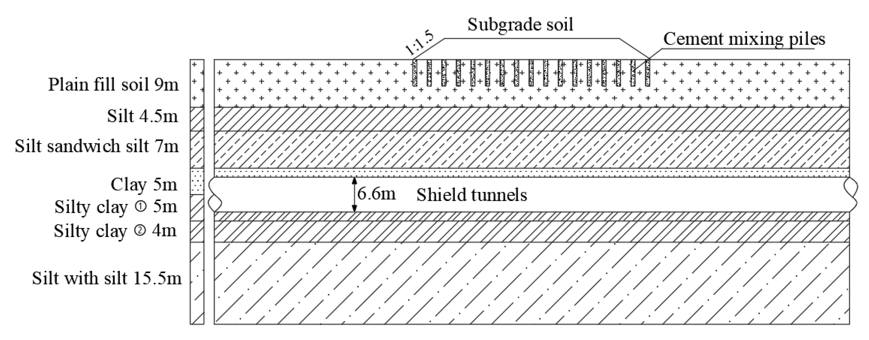
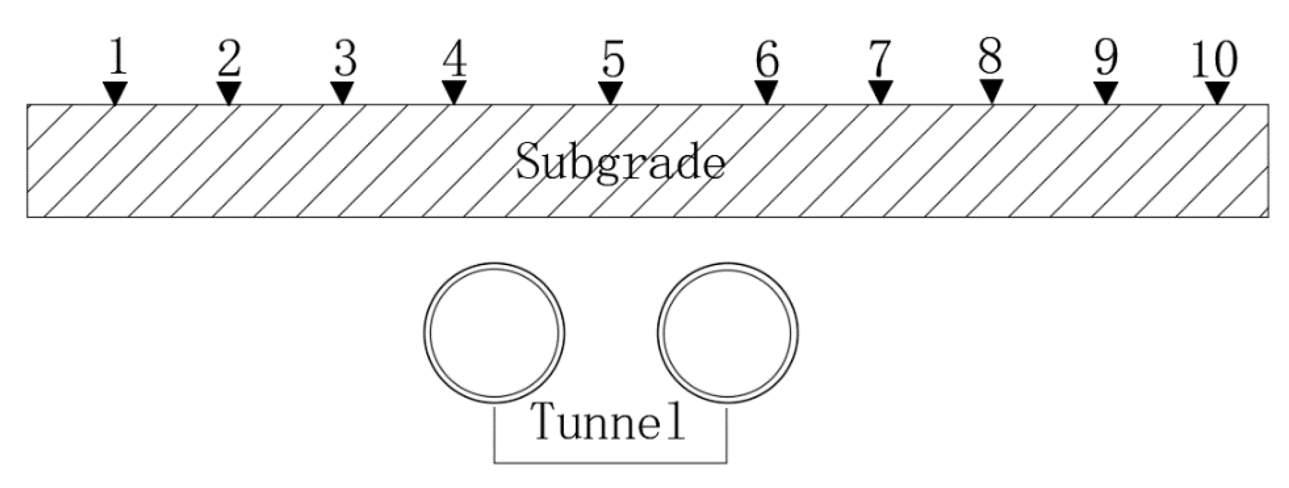
2.1. Project Overview

The angle between the shield tunnel design axis and the Shanghai—Nanjing expressway subgrade section was roughly 90°. The subgrade height and the total width were approximately 4 m and 44.25 m, respectively, with a slope of 1:1.5. Cement mixing piles of Φ 500 were set under the subgrade with an average depth of 5 m and a spacing of 1.2 m. The buried depth of the tunnel was approximately 20 m with a diameter of 6.6 m. The center line spacing of the parallel tunnel was 20 m and the thickness of the segment was 350 mm. The soil strata were mainly composed of clay and silty clay, as depicted in Figure 1. The physical and mechanical parameters of the soil strata are shown in Table 1.

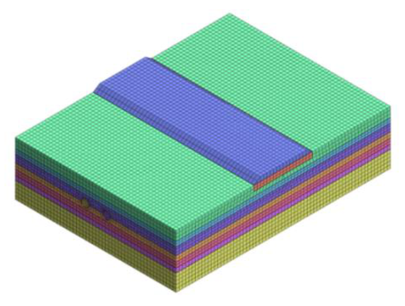
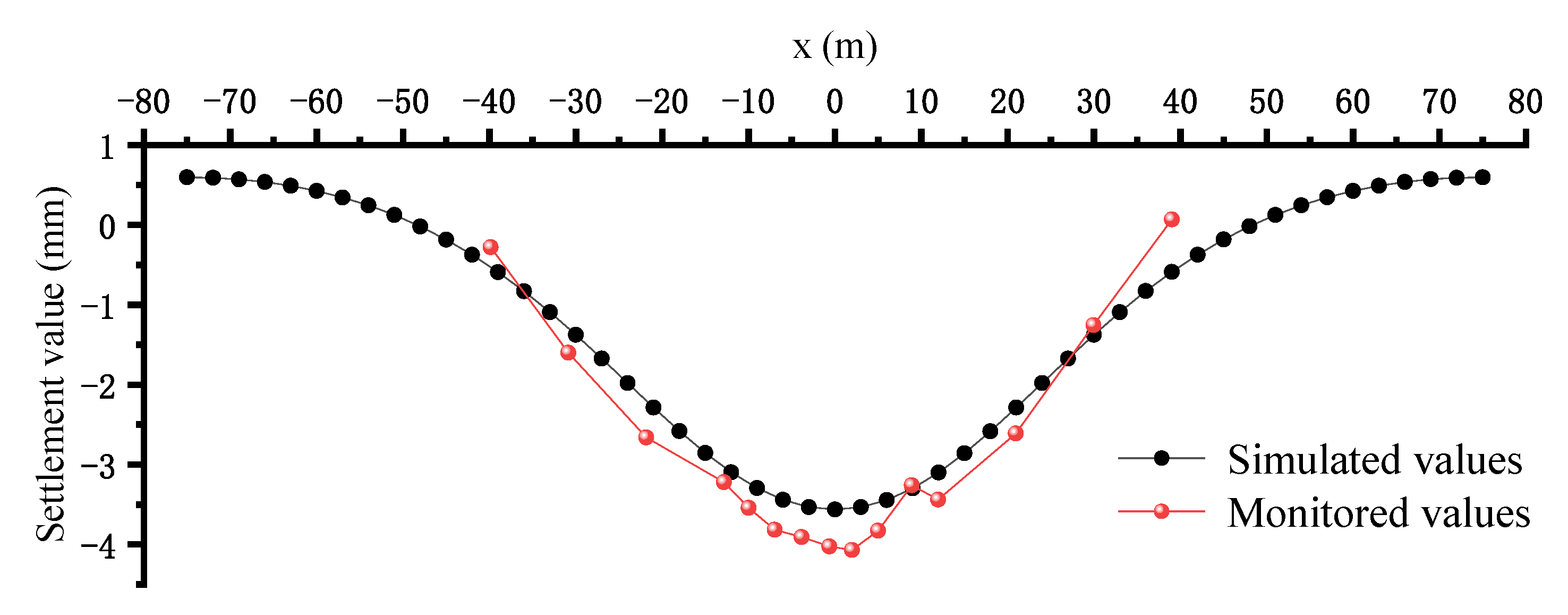
2.2. Finite Element Calculation

According to the relevant engineering and geological conditions as well as the actual engineering data based on MIDAS GTS NX finite element analysis software, a three-dimensional calculation model of shield tunneling under the expressway subgrade was established. The model size was 200 m in length, 150 m in width, and 50 m in height. The soil and subgrade were simulated using solid elements and the shell elements were adopted to model the segment and shield shell plate. A modified Mohr–Coulomb constitutive model was adopted for the soil; the segment and shield shell were assumed to be elastic, as shown in Table 2. The surface was free and the side boundaries were fixed in a horizontal direction whilst the bottom boundary was fixed in both the horizontal and vertical directions, as shown in Figure 2. In this paper, we set the construction steps according to the actual construction steps; that is, for each excavation ring with an excavation of 1.2 m, a total of 339 construction steps were set.
Based on the calculation results of the above finite element model, when the two lines were completed, the stratum deformation caused by the construction of the preceding tunnel was slightly larger than that of the subsequent tunnel. The maximum settlement of the subgrade soil was located directly above the axis of the shield tunnel; the settlement deformation was V-shaped, in line with the superposition principle of the Peck formula. The maximum settlement value of the subgrade soil was approximately 3.94 mm, and the maximum uplift value was approximately 0.66 mm. The maximum settlement value of the subgrade soil surface midline was approximately 3.47 mm, and the maximum uplift value was approximately 0.56 mm, as shown in Figure 3.

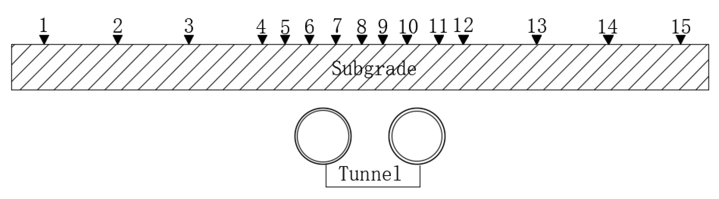
2.3. On-Site Monitoring of the Subgrade Settlement

Fifteen monitoring points were buried on the shoulder of the expressway, with a spacing of approximately 3 m above the tunnel and 9 m above the rest, as shown in Figure 4.
After the double-shield tunnel transfixion, the monitoring results showed that the maximum subsidence value of the roadbed shoulder by the numerical simulation of the double-shield construction was 3.56 mm. The measured settlement value was 4.07 mm, with a maximum subsidence value deviation of 0.51 mm. The error was small and the trends of the curve of the measured data and the numerical simulation were almost identical; both were in line with the Gaussian distribution, as shown in Figure 5. Therefore, we considered the numerical calculation results to be reasonable.

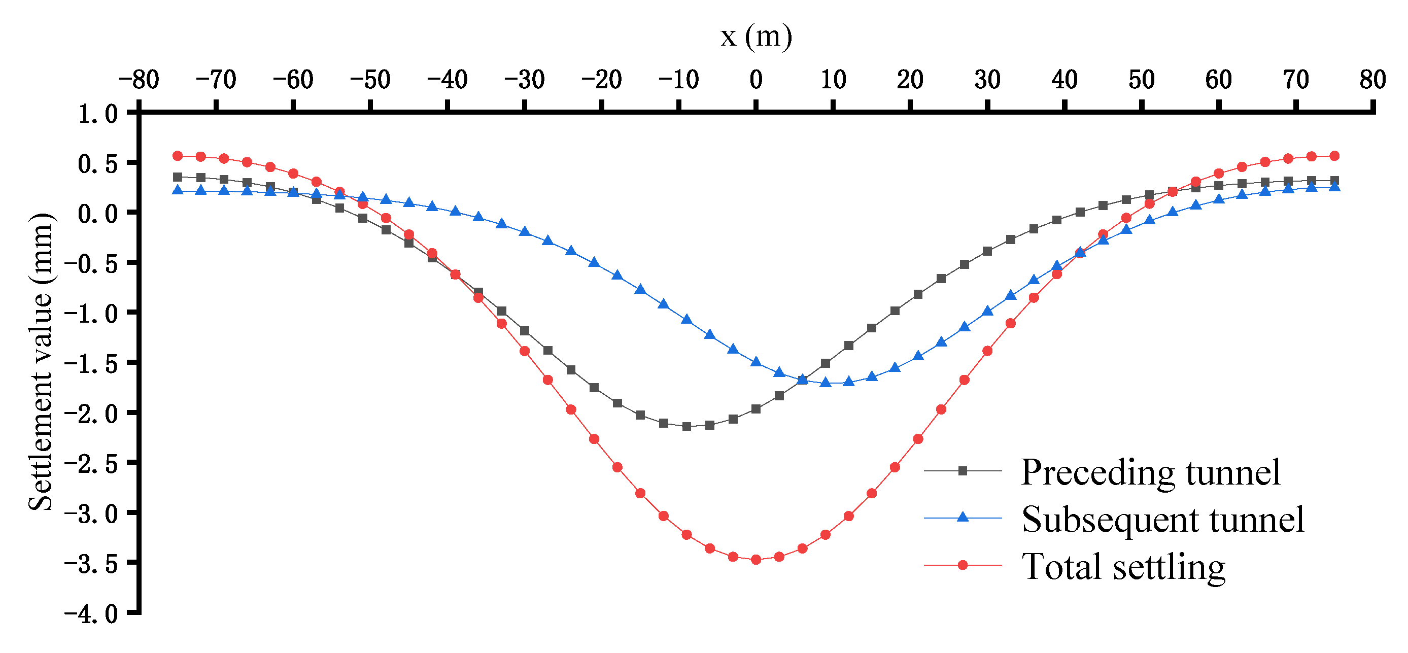
3. Analysis of the Subgrade Settlement Law

3.1. Calculation of the Peck Empirical Formula

Since Peck deduced the normal distribution regularity of a ground surface settlement formula on the basis of a large amount of field monitoring data from tunnel constructions in 1969, this formula has been one of the most widely used methods in the prediction of surface subsidence areas and has been widely applied to all types of tunnel engineering. The surfaces of the lateral predictions are expressed by Equations (1) and (2).
S x = S max exp x 2 2 i 2
S max = V L D 2 π 10 i
where S(x) is the vertical settlement value of point x; x is the longitudinal distance between point x and the tunnel axis; Smax is the maximum surface settlement; i is the settlement trough width coefficient; VL is the soil loss rate; and D is the tunnel diameter.
Mair et al. [13] summarized previous studies and found that the soil loss rate of a sandy stratum was within 0.5% and that of a soft clay stratum was approximately 1–2%. Wei et al. [14] observed that the soil loss rate of a clay stratum was between 0.2 and 2%.
O’Reilly [2] proposed that the width coefficient of the settlement groove correlated with the buried depth of the tunnel as well as the soil strata. The formula for a clay stratum is shown in Equation (3).
i = 0.43 H + 1.1
According to the engineering background above-mentioned, the buried depth, H, of the tunnel was 19.7~21.2 m; thus, 20.5 m was adopted. The tunnel diameter, D, was 6.6 m. The distance, d, of the tunnel center line was 20 m. The strata traversed mainly consisted of silty clay and clay strata, but were generally clay strata. It can be seen from Equation (3) that I = 9.915. Based on past engineering practice experience, the formation loss rate in shield construction is 0.85%. The above values were entered into Equations (1) and (2).
S x = 11.73 × exp x 2 196.6
In practical engineering, two parallel subway shield tunnels are generally not excavated at the same time. The preceding tunnel is usually constructed at a certain distance ahead of the subsequent tunnel. Therefore, ground surface settlement is not formed at one time during the excavation of a double-line tunnel, and ground surface settlement caused by the two tunnel lines is not completely consistent, which is due to stratum disturbance caused by the excavation of the preceding tunnel. In light of this engineering problem, Chen et al. and Wu et al. proposed solving this problem by adjusting the width coefficient of the settlement trough, as shown in Equations (5) and (6):
i k = k i
k = 1 + D d
where k is the correction parameter of the settling trough width coefficient; ik corrects the settlement groove width coefficient; and d is the distance between the double-track tunnels.
All parameters of the parallel double-track tunnel in this study were equal, except for the settlement groove width coefficient. Thus, the Peck empirical formula applicable to the double-track tunnel of this study was as shown in Equation (7):
S Dmax = S max exp x d 2 2 2 i 1 2 + 1 k S max exp x + d 2 2 2 i 2 2
In combination with this, k was 1.3667, then the ik was 13.551. This was obtained through Equation (7):
S Dmax = 11.73 1.1166 + 0.7317 × 11.73 1.1166 18.19 mm
According to the classical Peck formula, the maximum settlement value of a subgrade surface is approximately 18.19 mm, which was different to the field monitoring data and numerical simulation results in this study due to the particular highway subgrade. The expressway subgrade was treated with a cement soil mixing pile and the expressway subgrade itself had characteristics of high filling and high-pressure compaction. Therefore, it was necessary to use a modified Peck formula to predict the surface settlement of the subgrade section of the expressway in this study under the shield tunneling method in a similar engineering and geological area.

3.2. Modified Peck Empirical Formula

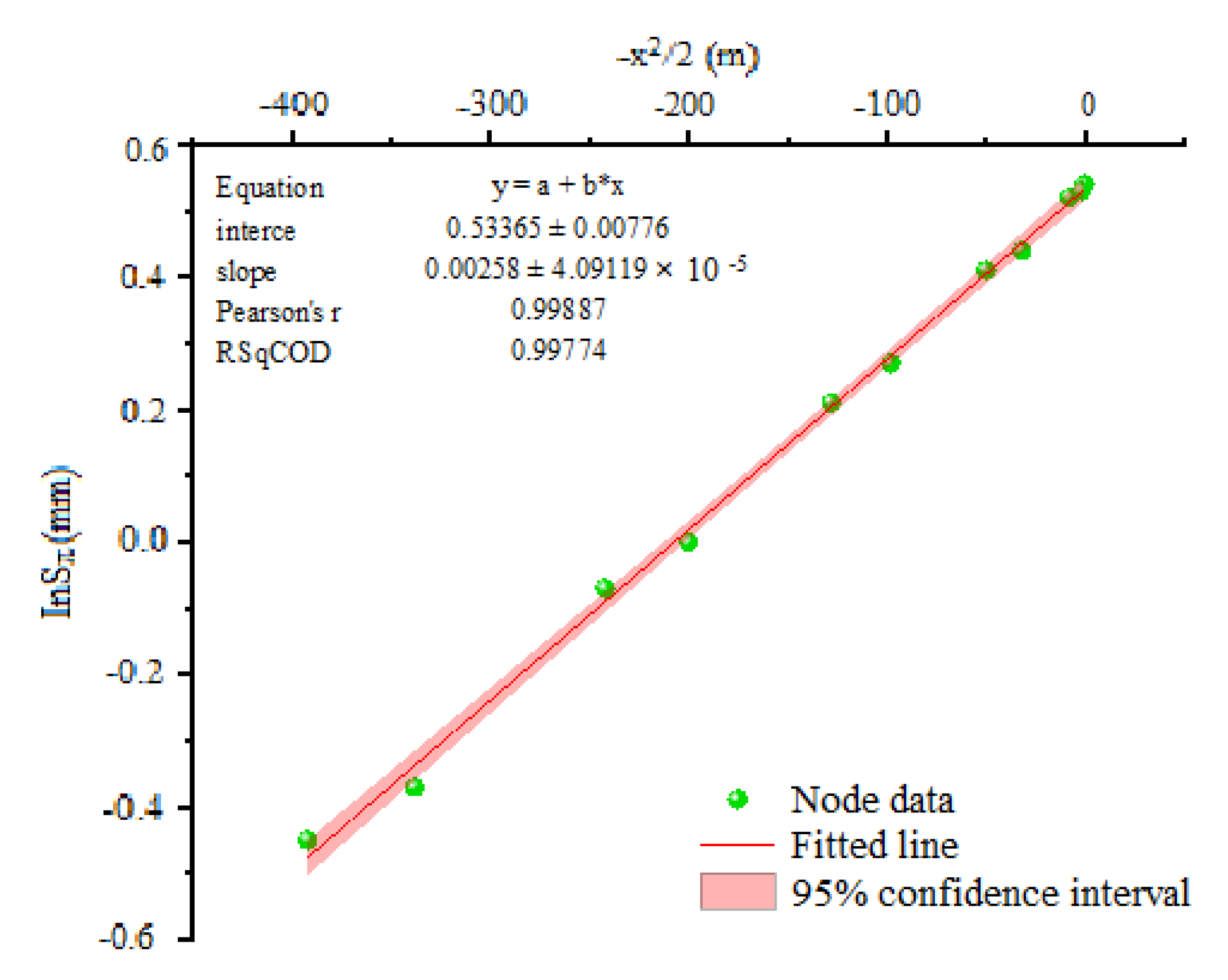
3.2.1. Linear Regression

Linear regression is a method for one or more independent variables and dependent variables according to the form of a known function to build the relationship; the fitting formula interpolation method, the polishing method, and the least square method are commonly used. As demonstrated above, the numerical simulation results in this paper were relatively accurate; thus, the numerical results were used as the sample data to modify the empirical formula.
For the Peck formula of the surface subsidence, namely, Equation (1), the e-based logarithm of both sides was obtained:
In S x = In S max x 2 2 i 2
If X = x 2 2 , Y = In S x , α = In S max , b = 1 i 2 . Equation (8) could then be changed to:
Y = a + b X
Thus, lnSmax was used as the dependent variable and −x2/2 was the independent variable. Through the linear fitting of the numerical simulation data of the preceding tunnel and the subsequent tunnel, the relevant correction parameters of the empirical formula suitable for similar projects were determined.
The data of the preceding tunnel and the subsequent tunnel are shown in Table 3 and Table 4. The x value in the two tables is the distance between the node and the tunnel center line of the line; that is, the same x value in the two tables does not mean that the two points were the same.
The linear regression results are shown in the figures below. Figure 6 shows that the linear fitting results of the preceding tunnel were:
Y = 0.74911 + 0.00235 X
According to Equations (8) and (9), we obtained:
In S x = 0.74911 + 0.002357 x 2 2
After the changes, we obtained:
S x = 2.13 × exp x 2 2 × 20.63 2
Figure 6 shows that the linear correlation coefficient of the node data of the preceding tunnel after the linear regression was approximately 0.972. The node data fell within the 95% confidence interval, indicating a high linear correlation.
Similarly, it can be seen from Figure 7 that the fitting result of the subsequent tunnel was:
Y = 0.53365 + 0.00258 X
After the changes, we obtained:
S x = 1.71 × exp x 2 2 × 19.69 2

3.2.2. Introducing the Correction Parameters

Peck [1] believed that the root cause of surface settlement was soil loss during tunnel constructions and that the width coefficient of the settlement groove determined the shape of the settlement groove. Combined with the numerical solution and the field monitoring data obtained above, the modification of the empirical formula introduced the soil loss rate correction parameter α and the settlement trough width coefficient correction parameter β, as shown in Equations (12) and (13):
S max x = α V l D 2 π 10 β i
S x = S max exp x 2 2 × β i 2
According to Equations (10), (12), and (13), we concluded that the preceding tunnel correction parameters were α1 = 0.38 and β1 = 2.08.
According to Equations (11)–(13), the correction parameters of α2 = 0.29 and β2 = 1.99 were obtained for the subsequent tunnel.
For the project of double-track shield tunnels under a highway subgrade section, the corrected empirical formula of the preceding tunnel was:
S x = 0.38 V l D 2 π 20.8 i exp x 2 2 × 2.08 i 2
The corrected empirical formula of the subsequent tunnel was:
S x = 0.29 V l D 2 π 19.9 i exp x 2 2 × 1.99 i 2
Figure 8 shows that compared with the classical Peck formula, the revised formula more accurately described the surface settlement curve when the shield tunnels were under the highway subgrade.

4. Validation of Similar Projects

To verify the reliability of the modified Peck empirical formula [1], we introduced another similar project [15]. The classical and modified Peck formulas were calculated and compared with the on-site monitoring data.
The shield tunnel was a double-track tunnel, the distance between the center lines of the two tunnels was approximately 20.5 m, the buried depth of the tunnel was approximately 18.5~25.1 m, the diameter of the tunnel was 6.2 m, and the intersection angle between the tunnel and the roadbed was approximately 90°. The foundation of the roadbed was cement and fly ash gravel pile and the crossing strata were generally clay strata. The related parameters of the two projects were similar; thus, the modified parameters obtained above could be used.

4.1. Classical Peck Formula Calculation

Substituting the relevant parameters into the classical Peck formula, i = 9.055 and Smax (x) ≈ 13.33 mm.
In the parallel double-track tunnel shield construction, considering the disturbance effect of the construction of the preceding tunnel on the subsequent tunnel, the settlement groove width coefficient was modified; that is, ik = ki, where k = 1 + D/d and ik = ki, ik was substituted into Equation (7), where
S Dmax = 13.33 1.1302 + 0.685 × 13.33 1.1302 19.87 mm
In this shield underpass high-speed railway subgrade project, the results calculated using the classical double-line Peck formula showed that the maximum settlement value was 19.87 mm.

4.2. Modified Peck Formula Calculation

The relevant parameters were added into the modified Peck formula of the preceding tunnel and the following equation was obtained:
S 1 max x = 0.38 V l D 2 π 20.8 i 2.25 mm
The maximum settlement of the subsequent tunnel was:
S 2 max x = 0.29 V l D 2 π 1.99 i 1.94 mm
In the construction of the parallel double-lane tunnel, the subgrade surface settlement was:
S Dmax = S 1 max exp x 1 2 2 × 2.08 i 2 + S 2 max exp x 2 2 2 × 1.99 i 2
The maximum settlement value was then:
S Dmax = 2.25 × 0.869 + 1.94 × 0.857 3.616 mm

4.3. Comparative Analysis of the Data

The layout of the monitoring points in this project is shown in Figure 9. The distance between the monitoring points was 5 m~7 m.
The monitoring data of the subgrade settlement is shown in Table 5 when the double-track tunnel was through.
Figure 10 shows that the maximum settlement point of the subgrade was located at the middle line of the double-track tunnel after the construction of the double-track shield tunnel in this project. The settlement rule was consistent with the modified empirical formula. The measured maximum settlement value was 5.32 mm. The modified empirical formula predicted the maximum settlement value of the double lines to be 3.66 mm; the classical Peck formula predicted the maximum settlement value of the single line and the double lines to be 13.33 mm and 19.87 mm, respectively.
The comparison between the classical Peck formula and the modified empirical formula showed that the latter was more accurate in predicting the settlement trough curve and the maximum settlement value.

5. Conclusions

(1)
In the construction of a double-track shield tunnel under an expressway subgrade section, the finite element calculation model based on actual engineering parameters can reflect the law of surface settlement in the construction process.
(2)
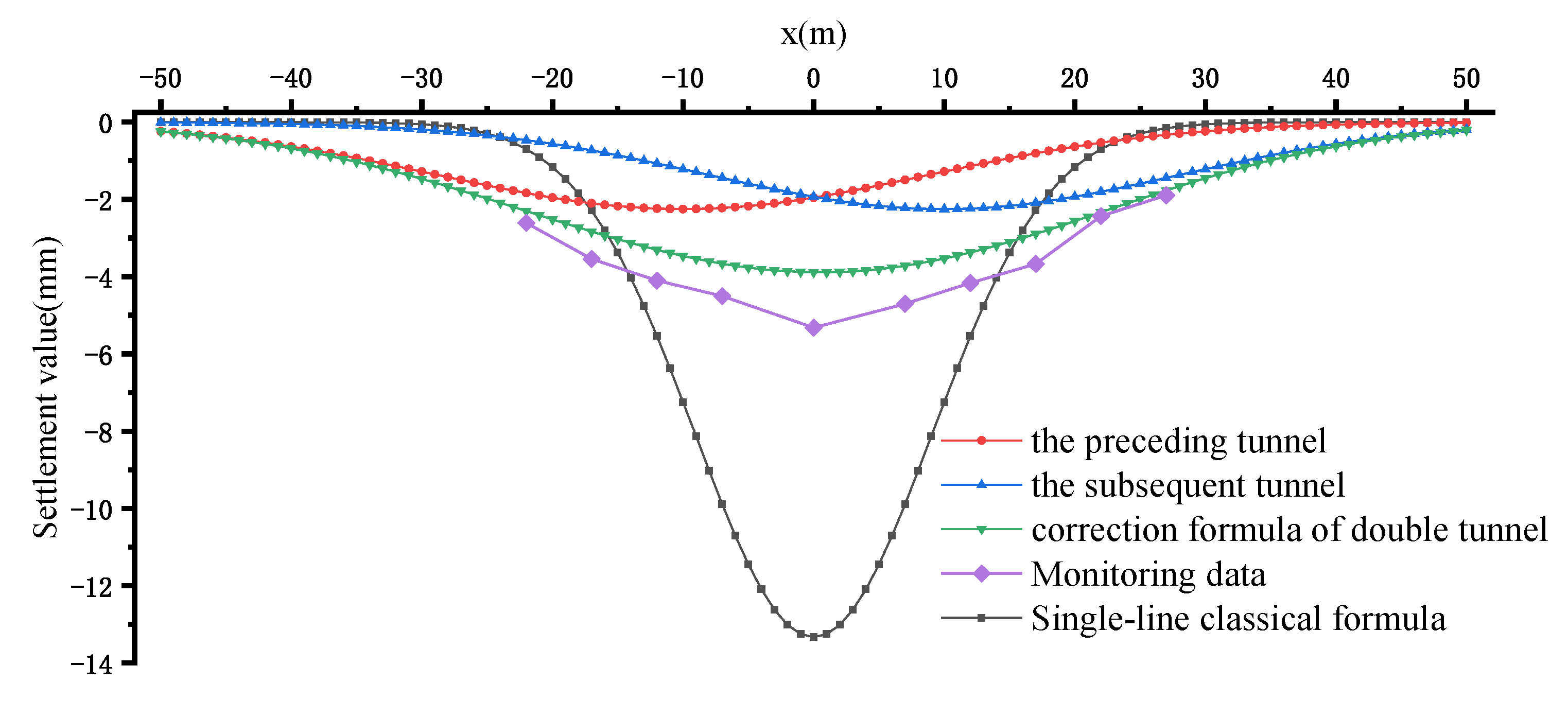
In the construction of the shield tunnel under the expressway subgrade section, there is a large error between the surface settlement value calculated based on the classic Peck formula and the actual monitoring data during construction.
(3)
The settlement of the subgrade surface caused by the excavation of the preceding tunnel and the subsequent tunnel was analyzed and fitted. By introducing two correction parameters (the soil loss rate and settlement groove width coefficient), the modified Peck empirical formulas applicable to the preceding tunnel (α1 ≈ 0.38 and β1 ≈ 2.08) and the subsequent tunnel (α2 ≈ 0.29 and β2 ≈ 1.99) were proposed. The results showed that the modified formula more effectively described the surface lateral settlement caused by the double-line shield tunnel through the highway subgrade section.
(4)
By introducing a similar project for verification, the reliability of the modified Peck empirical formula was verified. This had a certain engineering reference value and reflected the limitations of the modified formula. For other projects, it will be necessary to modify the model according to the specific engineering situation.
(5)
This paper takes the project of a double-track shield tunnel undercrossing highway subgrade as the research object, puts forward the modified Peck calculation formula suitable for this project, and summarizes the relevant conclusions, which can provide a certain reference value for the design and construction of similar projects.

Author Contributions

Conceptualization, Y.L. and S.Y.; Data curation, Y.L. and J.L.; Formal analysis, Y.L. and J.D.; Investigation, Y.L. and J.D.; Methodology, Y.L. and J.L.; Validation, Y.L. and J.L.; Writing—Original draft preparation, Y.L.; Writing—Review & editing, Y.L. and S.Y. All authors have read and agreed to the published version of the manuscript.

Funding

This research was funded by the Chinese National Natural Science Foundation (grant number 52068044).

Conflicts of Interest

The authors declare no conflict of interest. The funders had no role in the design of the study; in the collection, analyses, or interpretation of data; in the writing of the manuscript, or in the decision to publish the results.

References

  1. Zhu, C.H. Control of surface settlement by considering shield tunneling technology. KSCE J. Civ. Eng. 2017, 21, 2896–2907. [Google Scholar] [CrossRef]
  2. Duan, S.K.; Huang, L.; Bao, Z.; Shen, P. Application of modified Peck formula in surface subsidence prediction of Changsha subway tunnel construction. J. Nat. Disasters 2013, 24, 164–169. [Google Scholar]
  3. Li, X.; Zhang, D.; Hou, Y. Analysis of Shield Tunnel Ground Deformation Characteristics and Affecting Factors in Water-Rich Soft Stratum: A Case Study on the Section Tunnel of Tianjin Metro Line 6. Appl. Sci. 2022, 12, 6208. [Google Scholar] [CrossRef]
  4. Lei, M.F.; Lin, D.Y.; Shi, C.H.; Yang, W.C. A structural calculation model of shield tunnel segment: Heterogeneous equivalent beam model. Adv. Civ. Eng. 2018, 2018, 9637838. [Google Scholar] [CrossRef]
  5. Tan, Z.; Li, Z.; Tang, W.; Chen, X.; Duan, J. Research on Stress Characteristics of Segment Structure during the Construction of the Large-Diameter Shield Tunnel and Cross-Passage. Symmetry 2020, 12, 1246. [Google Scholar] [CrossRef]
  6. Spyridis, P.; Bergmeister, K. Analysis of lateral openings in tunnel linings. Tunn. Undergr. Space Technol. 2015, 50, 376–395. [Google Scholar] [CrossRef]
  7. Sun, J.C.; Zhang, H.; Peng, T.; Xiao, C.L. Research on Construction Mechanical Behaviour of Connecting Aisle in Shield Tunnel. IOP Conf. Ser. Earth Environ. Sci. 2018, 167, 012041. [Google Scholar] [CrossRef]
  8. Lu, P.; Yuan, D.; Luo, W.; Jin, D.; Liu, M. Centrifugal Model Test Study on the Mechanical Characteristics of Shield Tunnels Influenced by Different Types of Openings for Cross Passages. Appl. Sci. 2022, 12, 6421. [Google Scholar] [CrossRef]
  9. Xuan, H.; Ning, L.I.; Standing, J.R. An adaptability study of Gaussian equation applied to predicting ground settlements induced by tunneling in China. Rock Soil Mech. 2007, 1, 23–28+35. [Google Scholar] [CrossRef]
  10. Fang, E.; Yang, L.; Li, P. Prediction of Ground Settlement Induced by Metro Shield Construction Based on the Modified Peck Formula. Mod. Tunn. Technol. 2015, 52, 143–149+162. [Google Scholar] [CrossRef]
  11. Junju, T.; Kun, Z.; Song, C.; Yachong, X.; Peixin, Z. Inversion Analysis of Peck Formula Based on Zhengzhou Subway Running Down the Main Channel of South-to-North Water Transfer. Saf. Environ. Eng. 2021, 28, 109–113+132. [Google Scholar] [CrossRef]
  12. Yusheng, S.; Yonghui, H.; Le, Z.; He, W. Improvement of Peck formula of surface construction settlement of rectangular tunnel in soft soil area. J. Railw. Sci. Eng. 2017, 14, 1270–1277. [Google Scholar] [CrossRef]
  13. Bracegirdle, A.; Mair, R.J.; Taylor, R.N. Subsurface settlement profiles above tunnels in clays. Géotechnique 1993, 43, 315–320. [Google Scholar]
  14. Gang, W. Selection and distribution of ground loss ratio induced by shield tunnel construction. Chin. J. Geotech. Eng. 2010, 32, 1354–1361. [Google Scholar]
  15. Peixian, Q. Deformation Law and Control Strategy of the Subgrade under Shield Crossing High Railway. Master’s Thesis, Anhui Jianzhu University, Hefei, China, 2021. [Google Scholar] [CrossRef]
Figure 1. A schematic diagram of a longitudinal section of shield tunneling through the Shanghai–Nanjing expressway.
Symmetry 14 01904 g001
Figure 2. The calculation model of the highway subgrade under a shield method.
Symmetry 14 01904 g002
Figure 3. The deformation of the subgrade surface after the penetration of the double-track shield construction.
Symmetry 14 01904 g003
Figure 4. The layout of monitoring points at the subgrade shoulder.
Symmetry 14 01904 g004
Figure 5. The settlement curves of the shoulder monitoring data and simulated values after the penetration of a double-track tunnel.
Symmetry 14 01904 g005
Figure 6. The linear regression of the settlement curve of the preceding tunnel.
Symmetry 14 01904 g006
Figure 7. The linear regression of the settlement curve of the subsequent tunnel.
Symmetry 14 01904 g007
Figure 8. The Peck empirical formula and monitoring data before and after the correction.
Symmetry 14 01904 g008
Figure 9. The layout diagram of the roadbed monitoring points.
Symmetry 14 01904 g009
Figure 10. A comparison of the classical Peck formula, modified formula, and monitoring data.
Symmetry 14 01904 g010
Table 1. The physical and mechanical parameters of the soil layers.
Soil Layer NumberSoil Layer NameSevere γ (kN/m3)CompressibilityStationary Side Pressure Force Coefficient K0Consolidate Quick Cuts
Es1–2/(MPa)Ck/(kPa)Φk/(°)
①1Plain fill soil18.62/0.7515.012.0
③1Clay19.407.550.4346.915.7
③2Silty clay19.016.700.4832.316.0
③3Silt18.7210.530.457.125.0
④2Silt sandwich silt19.0112.050.423.632.4
⑤1Silty clay18.825.580.6027.915.3
⑥1Clay19.608.450.4150.916.1
⑥2Silty clay19.116.970.4531.915.0
⑦1Silty clay18.726.260.6027.315.8
Table 2. The partial material parameters.
ComponentUnit Weight/(kN/m3)Elastic Modulus/(kN/m2)Poisson’s Ratio
Segment253.45 × 1070.2
Shield78.52.1 × 1060.3
Table 3. The subgrade surface settlement data of the preceding tunnel (unit: mm).
Node1234567891011
x−26−20−14−8−21410162228
Sx0.801.191.581.912.112.142.131.981.681.340.99
x2/2−338−200−98−32−2−0.5−8−50−128−242−392
lnSx−0.220.170.460.650.750.760.760.680.520.29−0.01
Table 4. The surface settlement data of the subgrade along the subsequent tunnel (unit: mm).
Node1234567891011
x−37−28−19−10−4−128172635
Sx0.290.641.081.501.681.711.701.561.150.690.29
x2/2−685−392−181−50−8−0.5−2−32−145−338−613
lnSx−1.24−0.450.080.410.520.530.530.440.14−0.37−1.24
Table 5. The settlement monitoring.
Monitoring Point Numberx/mMonitored Settlement Value/mm
1−22−2.61
2−17−3.54
3−12−4.1
4−7−4.5
50−5.32
67−4.7
712−4.16
817−3.67
922−2.43
1027−1.89
Publisher’s Note: MDPI stays neutral with regard to jurisdictional claims in published maps and institutional affiliations.

