Article

Unsymmetrically Distributed Bolt Axial Forces between Symmetrically Spaced Bolts of Clamping Sleeve

Department of Machine Parts and Mechanisms, Faculty of Mechanical Engineering, VSB-Technical University of Ostrava, 70800 Ostrava, Czech Republic
*
Author to whom correspondence should be addressed.
Symmetry 2023, 15(10), 1893; https://doi.org/10.3390/sym15101893
Submission received: 30 August 2023 / Revised: 4 October 2023 / Accepted: 6 October 2023 / Published: 9 October 2023
(This article belongs to the Section Engineering and Materials)

Abstract

:
This article deals with the uniformity of the distribution of axial forces between the individual bolts of the clamping sleeve. Clamping sleeves are machine components connecting the shaft to the hub using contact force. For sleeve pretension, bolts are used and positioned symmetrically with respect to the axis of the clamping sleeve. Though the bolts are placed symmetrically around the axis, the bolt axial forces are not uniformly distributed when the bolts are tightened according to the manufacturer’s catalog. First, this article describes the procedure for tightening the sleeve bolts according to the manufacturer’s catalog. In the next part of the article, an FEA simulation of sleeve tightening is performed. The FEM simulation is then compared with the values found by measurement.

1. Introduction

Clamping sleeves are machine components connecting the shaft and hub. In today’s technical practice, they are very often used for their advantages, but they also show failures, for example in [1,2]. They work on the principle of a frictional force. To develop contact pressure, which is important for the function of the joint, it is necessary to pretension the clamping sleeve bolts. These bolts are often distributed symmetrically around the axis of the clamping sleeve. In this article it is the Rexnord Tollok TLK 400 clamping sleeve in dimensions 50 × 80 mm used [3]. More detailed information about the clamping connections in general can be found, for example, in [4].
This sleeve is pretensioned with eight M8 bolts placed symmetrically around axis of the clamping sleeve. A view of the sleeve and a description of the bolts is shown in Figure 1. Even with the symmetrical distribution of the clamp sleeve bolts, after tightening the clamp sleeve bolts according to the manufacturer’s catalog, the bolts axial forces between bolts are not symmetrically distributed. In general, it can be said that a relatively large error is introduced into the tightening by the conversion of the tightening moment of the bolts, which is given by the manufacturer, into the axial force, which is important for tensioning. The precise determination of the axial force from the tightening moment is problematic due to several complexly determined values. The solution to this problem can be a specialized device that tensions the bolt by axial force and then tightens the nut freely [5,6]. It is not possible to use this method of tightening the bolts of the clamping sleeve due to the shorter bolts.

1.1. Uniformity with Respect to the Tightening Sequence

The uniformity of the distribution of axial forces between the individual bolts can affect the contact pressure and therefore the maximum operating load that the sleeve will carry. The uniformity of axial forces due to the tightening procedure is investigated, for example, in [7,8,9]. In none of the articles mentioned above are the uniformity of axial forces and therefore also the uniformity of stresses and pressures of the clamping sleeve addressed. Very often, the tightening procedure for flanged sealing surfaces is solved [10,11], where, of course, the uniformity of the axial force in the bolts has an influence on the uniformity of the pressure acting on the seal, which is needed for the correct functioning of the seal. It is at this point that the similarity between this flanged sealant joints and a clamping joint becomes apparent, where the pressure acting on the tapered surfaces and cylindrical surfaces to transfer the load is essential to the correct function of the joint. In the case of these complications, simultaneous tightening of all bolts at the same time seems to be of great interest; equipment for such tightening is offered, for example, by SKF [12].

1.2. Bolted Connections

We can identify several types of clamping sleeves, including the number of bolts and their location. A clamping sleeve with several bolts around the axis is probably the most used. These bolted connections interact with each other, and the bolted connection solution we are dealing with is a multi-bolted connection. The issue of multiple bolted connections is addressed, for example, in VDI 2230 in its second part [13]. According to VDI 2230, multiple bolted connections are also recommended to be solved using FEM. The FEM simulation verified by the experiment is included, for example, in [14,15,16].
Due to several typical characteristics of the clamping sleeve, it is not possible to use a common diagram of a pretensioned bolted joints, which can be found in the common literature, for example, in [17,18]. Fundamental to the impossibility of using typical analytical calculations are the conical surfaces, which have a very small conicity, and relatively large displacements of these cones occur during tightening. When considering the total deformation (displacement), the stiffness of the flanges is very low. Due to the very atypical properties of the bolted connections of the clamping sleeve, it is not possible to apply the knowledge of force distribution to conventional bolted connections well enough. For this reason, which is also the point of the paper, FEM and measurements are used rather than analytical calculations using the pretensioned bolted joint diagram.
Due to the impossibility of using an analytical calculation because of the very atypical bolted connection, two alternative methods are used. The FEM simulation of clamping sleeve bolted connections is used. From the literature, in the case of the impossibility of analytical calculation, it is quite possible to use FEM [19]. FEM serves very well in applications where the bending moment of bolts can be expected [20], which is also the case with the clamping sleeve. In addition to the possibility of using the FEM, another option for determining the axial force in the bolt is measurement.

1.3. Measuring Bolt Axial Force

Measuring the axial force in bolts is quite common in technical practice and is used in cases where we do not know the axial force in the bolt and we need to determine it accurately. One variant is the FEM simulation, which determines the force in the bolt. The advantage of this method is the ability to accurately model, for example, the input force. However, we make simplifications in several parameters, such as surface structure, material properties or manufacturing inaccuracies, so we often proceed to measure the axial force directly on the actual component. The disadvantage is the frequent need for adjustment and therefore measurements differ from the actual state.
There are several ways to measure the axial force in a bolt. Probably the most common in practice is the use of an axial force transducer, which is most often a strain gauge device. In technical practice, it is often not possible to use purchased sensors due to their dimensions, so we usually use sensors made exactly for the application [21]. The sensor in the form of a housing with a strain gauge is discussed, for example, in the article [22]. Another method that is less common is the optical sensor method [23]. These methods need a housing with strain gauges, so they change the stiffness of the flanges. Another option is to use the bolt as a sensor. In this case, it is necessary to reduce the preload and consider the change of the bolt stiffness. Very often the bolt is fitted with two strain gauges [24], which are connected to one bridge.

1.4. FEM Simulation

FEM simulation involves converting a real problem into a 3D model and setting boundary conditions. It is the setting of the boundary conditions that is the biggest problem, which is why the verification of the FEM model is usually achieved using measurements, such as in these articles [25,26,27]. The FEM model was setup considering information from the following sources [28,29,30]. FEM is described in Section 2.4. It used Ansys Workbench 2020 R2 from Ansys manufacturer from Canonsburg, PA, USA.

2. Materials and Methods

The basic requirement is to use as many values as possible from the manufacturer’s catalog to respect the real application situation as much as possible.

2.1. Values from the Clamping Sleeve Manufacturer’s Catalogue

Fundamental to this issue is the procedure for tightening the clamp sleeve bolts and lubricating the clamping sleeve, which has a significant effect on clamping sleeve tightening. For the previously defined clamping sleeve, TLK 400 50 × 80, it is possible to find the bolt tightening torque value in the manufacturer’s catalog. The tightening torque value in the manufacturer’s catalog is for unmodified bolts and for transferring the working load of the sleeve. The TLK 400 50 × 80 sleeve is pre-tensioned with 8 bolts with a tightening torque of 41 Nm. In addition to the tightening torque, the tightening procedure is also defined as follows:
  • Tighten the bolts crosswise to half torque;
  • Tighten the bolts crosswise to full torque;
  • First time around the circumference to full tightening torque;
  • Second time around the circumference to full tightening torque.
So, if we divide this procedure into individual steps, we reach the 32-consecutive-step increments of bolt pretension force.

2.2. Input Data for FEM

For the FEM model, it is first necessary to determine the input values. These values are not part of the clamping sleeve manufacturer’s catalog. The calculation of input values for the FEM model was determined, for example, in [31]. The input values were the dimension of the sleeve, the tightening toque of the Bolts and the pressure of the shaft or hub from manufacturer’s catalog. The frictional properties on the sleeve, bolt and the axial force in the bolts are unknown. Due to the necessity of using a numerical calculation method, the solution was performed using MathCad from the PTC company based in Boston, USA. From the contact pressure acting on the shaft and the tightening torque of the bolts, other parameters needed for the FEM model were determined.
In the manufacturer’s catalog, the tightening torque is defined in the form of a tightening torque. It is first necessary to define the equation for calculating the axial force in the bolt from the tightening torque. Equations (1)–(4) are from [32].
F o = M u f · D s 2 + tan ψ + φ · d 2 2
M u is the tightening moment of the bolts, F o is the bolt pretension force, and f is the friction coefficient under bolt head and on conical and cylindrical surfaces. D s 2 is the middle friction diameter, and d 2 2 is the major diameter of thread. The middle friction diameter is the diameter between bore diameter of the Bolt and diameter of the Bolt head.
However, this equation is very general and does not sufficiently define the exact application of this bolted connection in the clamping sleeve. A more accurate application of this equation with the application of a clamp sleeve is possible by using the equation to calculate the contact pressure on the shaft from tightening the clamping joint.
p H = 8 · M u f · D s 2 + tan ψ + φ · d 2 2 π · d h · l h · ( tan β + f )
The contact pressure p H acting on the shaft is based on the clamping sleeve as given in the manufacturer’s catalog. Other parameters, such as the length of the sleeve l h , shaft diameter d h , the angle of the cone β , etc. are based on the 3D model of the clamp sleeve.
To fit the equation, it is necessary to define two more equations representing the parameters of the bolt thread:
Thread pitch angle:
ψ = arctan P h π · d 2
where P h is a thread pitch.
Reduced friction angle:
φ = arctan f z cos α 2
In Equation (4), after adding the other equations, we have three variables: the axial force in the bolt F 0 , the coefficient of shear friction on the thread f z , and the coefficient of shear friction on the conical and cylindrical surfaces of the clamping sleeve f . Due to the number of variables in one equation, it is necessary to use the numerical method for the calculation. We used the numerical calculation method in MathCad 15 from PTC based in Boston, MA, USA. The preset tolerance in MathCAD was used; The tolerance = 0.001. Two consecutive iterations of the calculation must not differ by more than 0.001. The solution therefore results in the following values and was applied to the tightening moment from catalog 41 Nm: the coefficient of shear friction on the thread f z = 0.1 , and the coefficient of shear friction on the conical and cylindrical surfaces of the clamping sleeve f = 0.13446 . The calculated force pretension in the bolt was F 0 = 30,200   N .
These values found by the numerical method were verified by back substitution into Equation (2), and the tightening moment was calculated. The behavior of the FEM model with the following values as parameters was also verified: The correct function was checked with respect to contact pressure. The contact pressure acting on the shaft or the bore in the hub was compared to the pressure specified by the clamping sleeve manufacturer in the catalog. FEM analysis settings is the same as 2.4. Even bolt pretension is an original force from Equation (1).
The catalog pressure value for the unmodified clamping sleeve acting on the shaft is 147 MPa, and for the pressure acting on the hub bore, it is 95 MPa. These values were therefore compared to the values of the average contact pressure acting on the surfaces of the shaft or the hub bore after the tensioning of the sleeve by axial forces in the bolts. The FEM mean contact pressure values are 144.4 MPa for the shaft and 87.6 MPa for the hub bore. The contact pressure on the shaft and hub bore is shown on Figure 2 and Figure 3. The pressure determined using FEM is lower than the catalog pressure for both the shaft and the hub bore, but the difference is acceptable. The input values determined by the numerical calculation method are correct, the setting of the FEM model with these values is correct. The settings of this test model and the model used later in this article are the same.

2.3. The Principle of Measurement

To evaluate the uniformity of the distribution of axial forces between individual bolts, the axial force in the bolts of the clamping sleeve is evaluated. The axial force was determined using two strain gauges placed on each bolt of the clamping sleeve, A schematic representation of the strain gauges on the bolt and the bolt with the strain gauges glued on is shown in Figure 4 and Figure 5. Torque wrench has an uncertainty of 5%, and uncertainty from the measuring of the axial force with the strain gauge is under 2%. An HBM strain gauge 1-LY41-1,5/120 was used [33]. R1 was used with a strain gauge with resistance of 120 Ohm, and R2, R3, and R4 were replaced by resistors with 120 Ohm resistance.
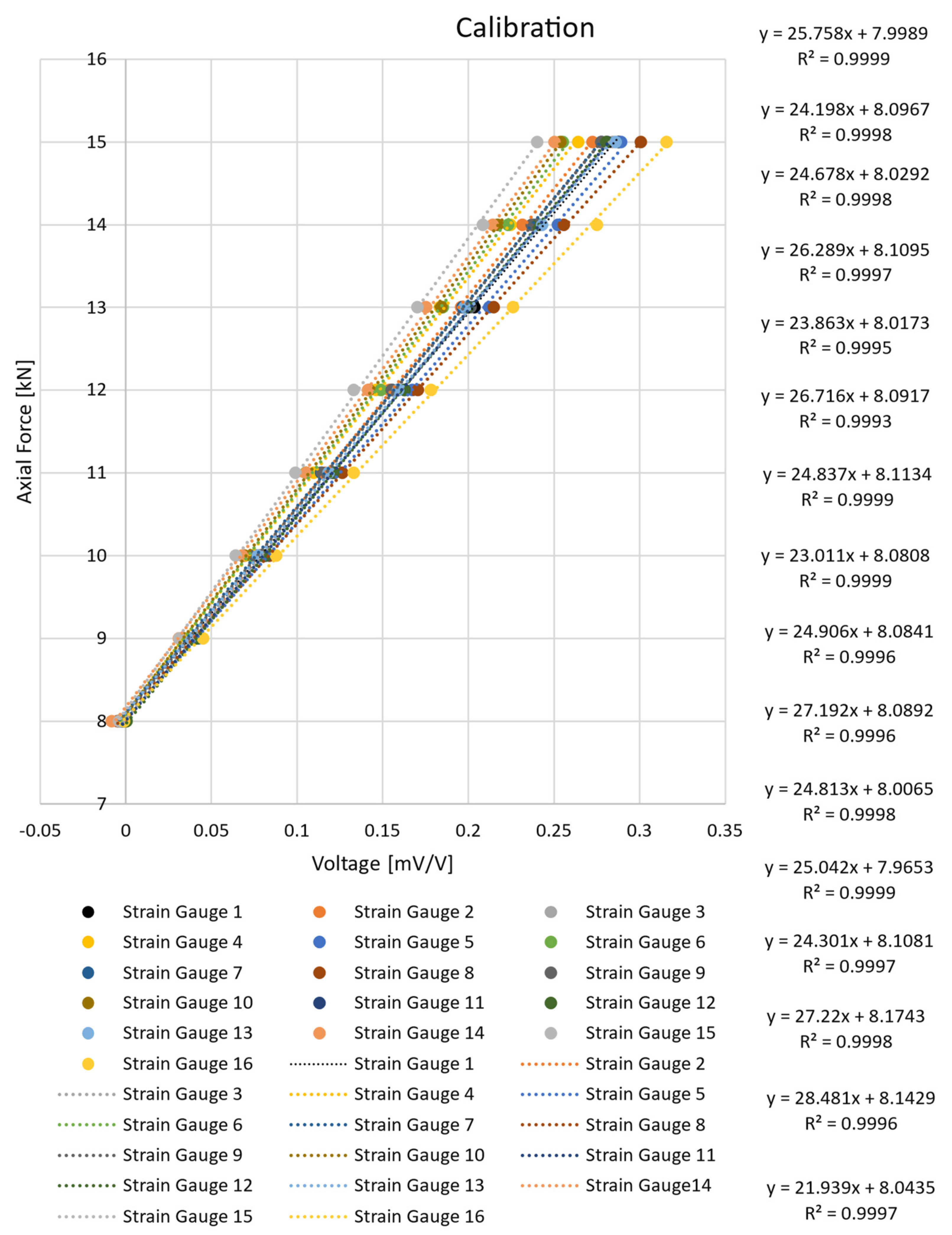
Due to the modification of the bolts, the calibration of the bolts continued. Calibration was carried out under tension on a tearing device. Both strain gauges on the bolt were always calibrated simultaneously. The values determined by the calibration were plotted on a linear curve, as shown in Figure 6. The calibration curves were then moved to the origin, and the curve directives were added as a constant to the measurement program for each strain gauge separately. The output of the program that was stored is the axial force under each strain gauge. The mean value of the axial force in the bolt can be determined as the average between both strain gauges. The separate connection of each strain gauge also allows us to detect the possible bending of the bolts.
Due to the reduction in the bolt diameter for strain gauges and to the axial drilling for the cable entry, the tightening torque and thus the axial force in the bolt need to be reduced. The calculation of the reduced torque with respect to axial and radial bolt penetration is given in [31]. The tightening torque was reduced to 20 Nm. For this tightening moment, the axial force, which is the boundary condition of the FEM, was calculated using Equation (1). The axial force in the bolt and the tightening torque are given in Table 1.
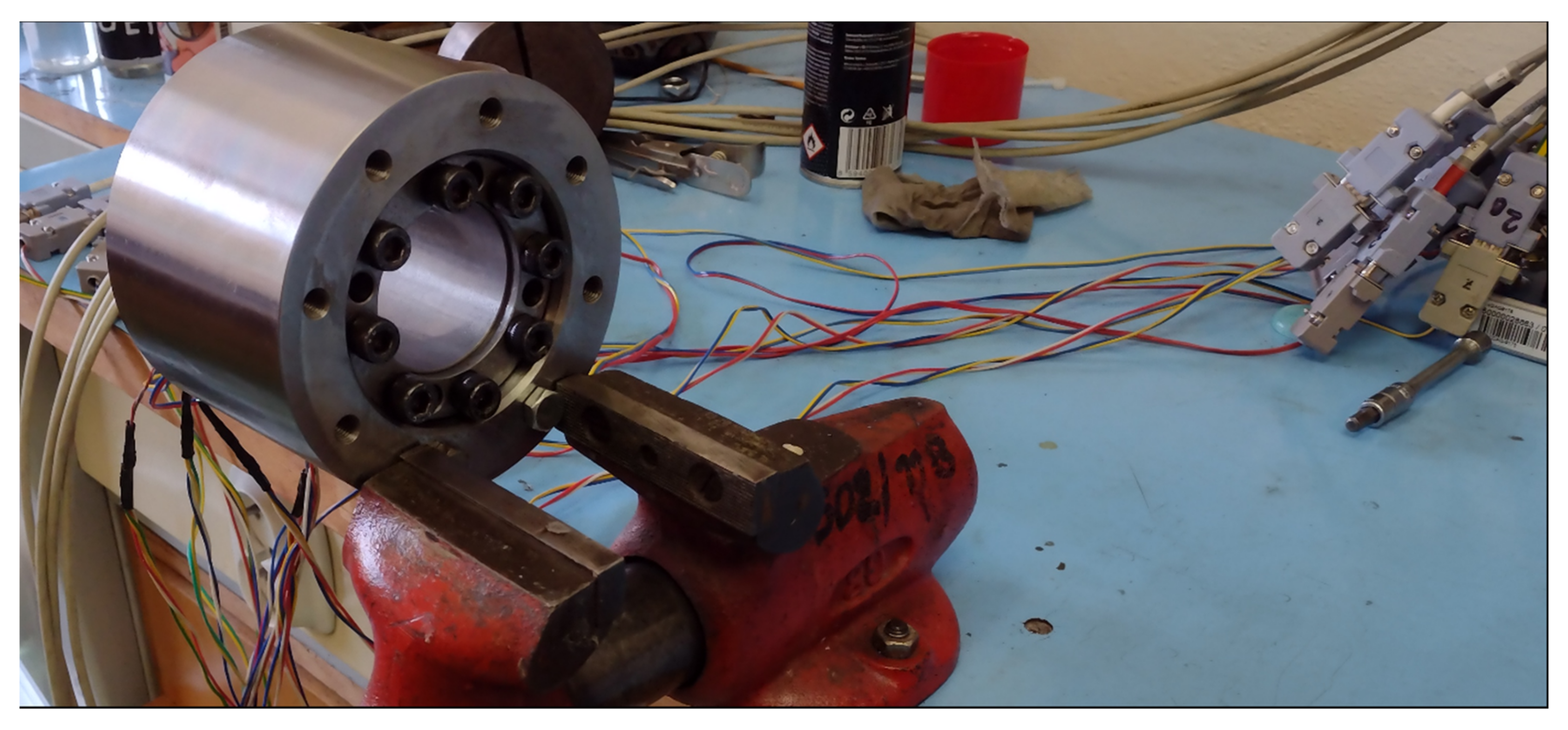
Measurements were taken at rest. The hub was clamped solid and fixed. The only input load acting on the construction is the load from the clamping sleeve preload. Machine components replacing the shaft and hub were manufactured for measurement purposes. The component replacing the shaft is basically just the cylindrical surface of the shaft on which the clamping sleeve is placed. The hub is essentially a hollow cylinder. The outer diameter of the hub corresponds to the minimum required hub diameter according to the clamping sleeve manufacturer’s catalog. The fixing of the clamping sleeve is shown in Figure 7.
The measurement uncertainty represented by the deviation obtained from the calibration is up to 2%.

2.4. FEM Model Parameters

Some parameters of the FEM model have been referred to in the section above. This chapter will be focused on the setup of the FEM model of the clamping sleeve.

2.4.1. Geometry and Mesh

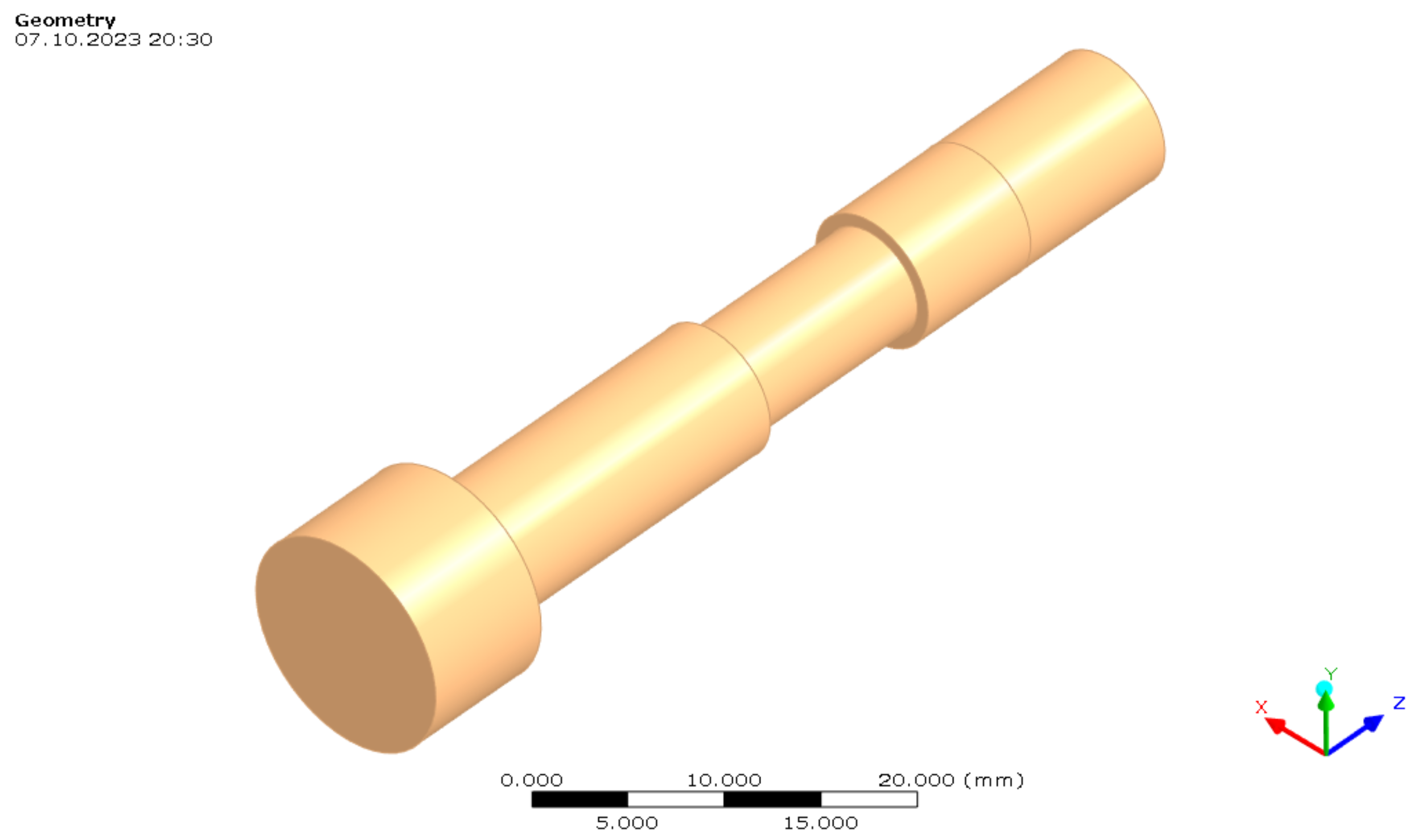
In terms of geometry, the model was designed to be as close to real as possible. This model uses modified bolts that have a reduced outer diameter to bond the strain gauges. For the reasons of meshing and convergence of the calculation, the axial and radial drilling on the bolts were ignored. The bolt is shown in Figure 8.
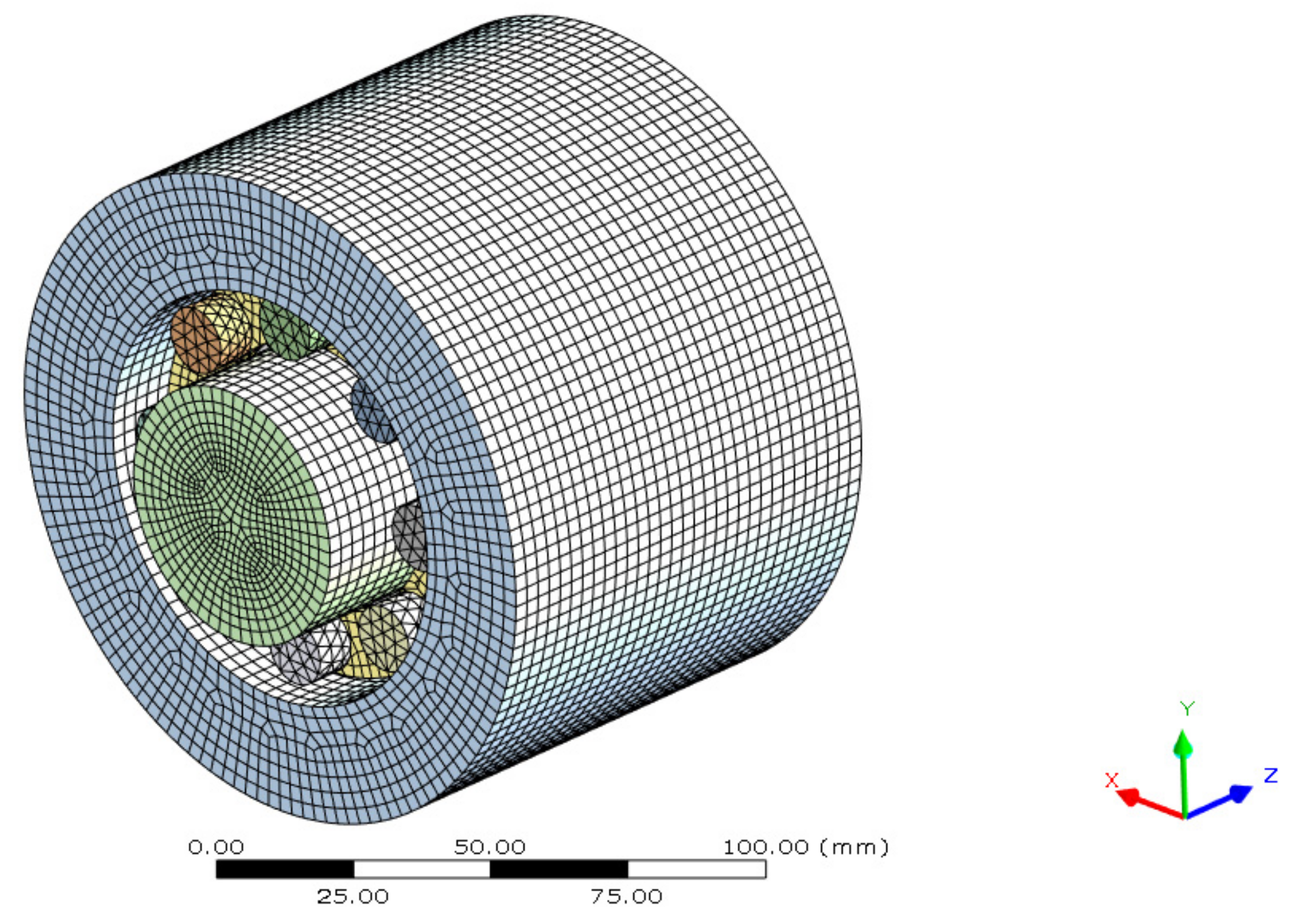
The mesh has a major impact on the convergence of the FEM model. The best converging mesh was created automatically according to the preset parameters of Ansys Workbench 2020 R2 based on Canonsburg, USA Figure 9.
To achieve the final quality of the mesh, only the refinement of the mesh on individual elements was used Figure 10. No other modifications to the mesh in terms of the meshing methods used resulted in the creation of the mesh or convergence of the calculation. The complications with the creation of the mesh are mainly due to the very small areas created by the modification of the bolts or the relatively thin structures on the rings.
The modified FEM model mesh has a smaller element size. The global element size is set to 5 mm. The cones and rings of the sleeve are resized to 3 mm. The mesh has a 22,643 elements and 84,721 nodes. It uses 9269 tetrahedrons (10 elements); 13,190 hexahedrons; 20 elements; and 184 pentahedrons (15 elements).

2.4.2. Contacts

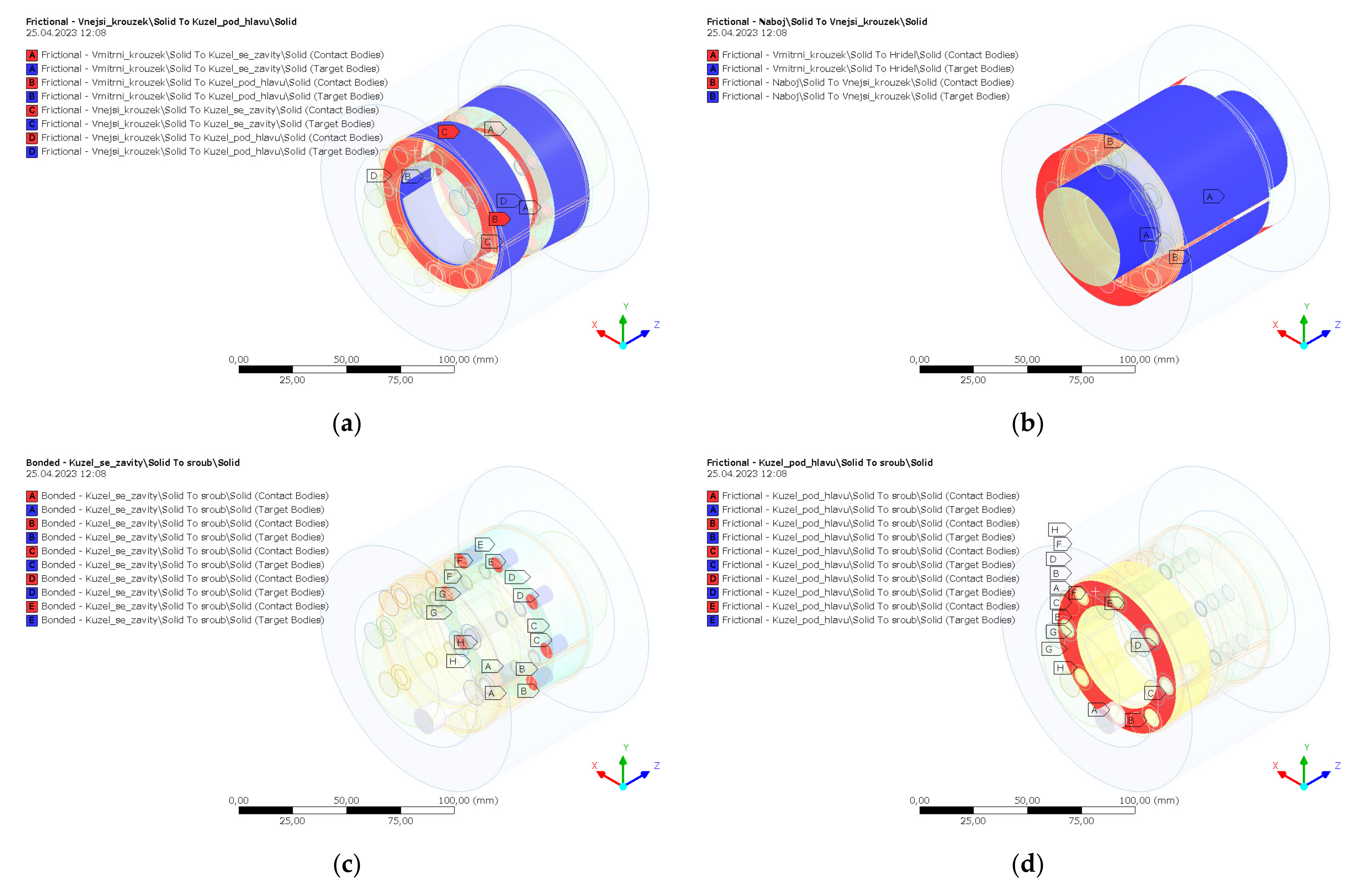
The contacts shown in Figure 11 between the individual components of the model are very important from the FEM analysis setup and for convergence. Under the bolt head, frictional contact was used with a friction coefficient of 0.15. On the cone and on cylindrical surfaces between the shaft and sleeve as well as between the hub and sleeve, frictional contact was used with a friction coefficient of 0.13446. For the bolt thread, bonded contact was used.

2.4.3. Boundary Conditions

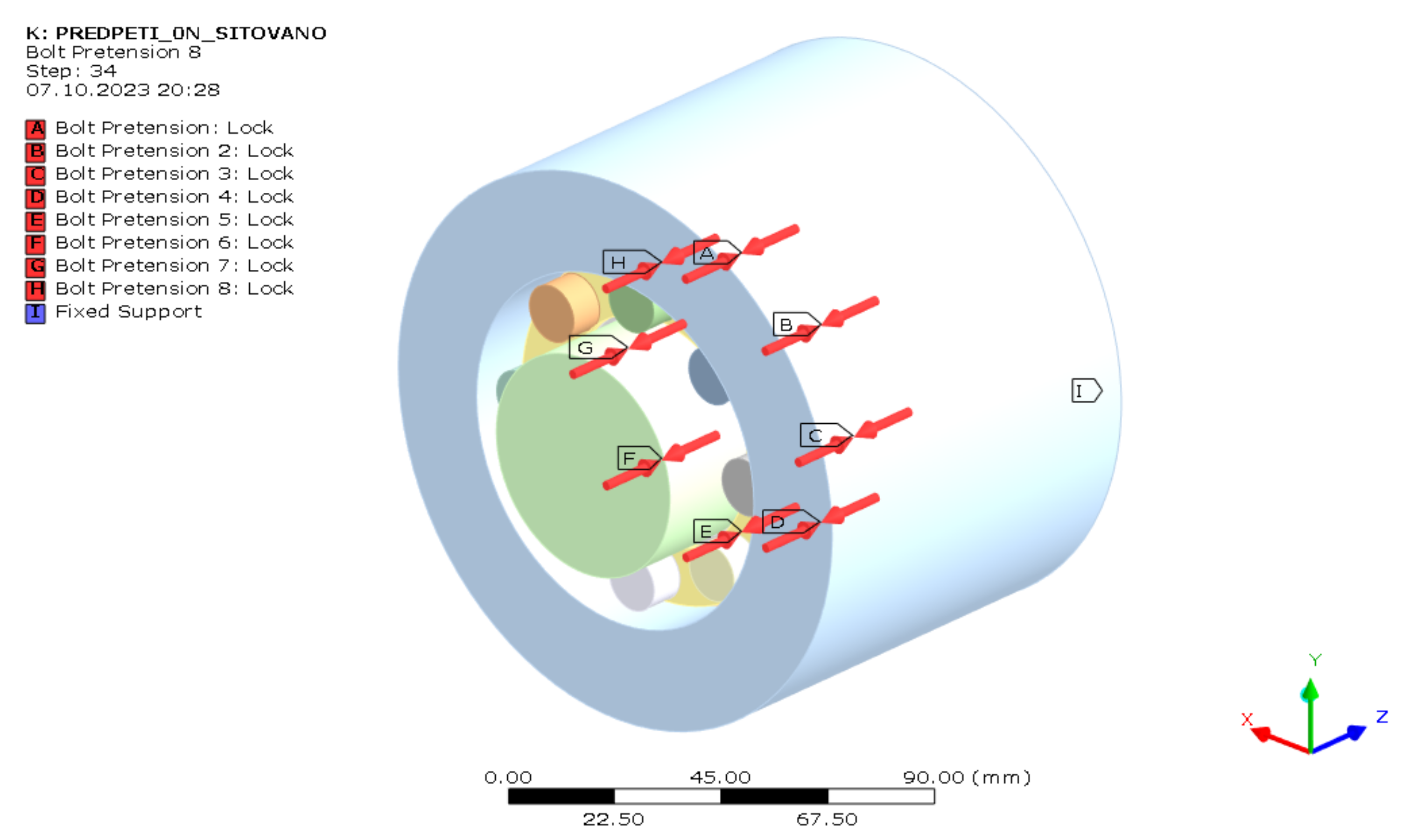
The boundary conditions of the FEM model sleeve respect the real measurements as much as possible. The load is defined by the bolt pretension function, as shown in Figure 12. The construction is fixed in space by a “Fixed Support” constraint defined on the hub head.

2.4.4. Material Properties

Only structural steel was used in this analysis. The material properties of the structural steel is described in Table 2. The linear material properties are from the Ansys database.

2.4.5. Loads

Very important in the case of the FEM model setup is the number of analysis steps. The originally planned number of 32 steps was increased to 34 by adding one step at the beginning and one at the end of the analysis. The first step was added for the convergence of the calculation. The bolts in the first step were preloaded to 0 N, and from this value, the axial force in the individual bolts is increased. The last step is the step that should represent the steady state after tightening. Bolt pretension in each step is described in Table 3.
The analysis is very complicated in the convergence perspective. To ease convergence, a change has been made to the convergence criterion. Moment convergence, deformation convergence and rotational convergence have been removed. The only criterion for convergence is force. The tolerance for convergence was set at 5%. The total number of iterations through each step was 55.

3. Results

The results are presented in two chapters, the results from the measurements and the results from the FEM.

3.1. Measurements Results

Several measurements were made. The values presented in this article are the average of all measurements that have been made. To be able to merge several measurements together and to compare measurements and FEM, values from each measurement were written out only in the same steps, and as is in the case of FEM, this was always performed after the tightening one of the bolts. For illustration, the values have been presented in the same table as for the FEM boundary condition (see Table 4). Measurements were made using NI 9327 measurement cards and LabVIEW 2017 software. LabVIEW 2017 from Austin, TX, USA, was used. The value in mV/V was measured for each single strain gauge. The value of each strain gauge was already converted to a force in N in LabView Software using a calibration constant. Then, the average of the two strain gauges was calculated for each screw as the tensile component of the force. The measurement uncertainty represented by the deviation obtained from the calibration is up to 2%.
The last row of measured data shows that the axial force in all bolts is lower than the axial force from Table 1. The last bolt to be tightened, i.e., bolt 8, is the closest to the nominal required value of the axial force.
Average force in the bolts at step 25:
F pm 25 = F o 25 i = 9249.2   N   ± 2 %
Average force in the bolts in step 34:
F pm 34 = F o 34 i = 11,303.7   N   ± 2 %
During tightening, the axial forces in the bolts increase, and the axial forces become homogeneous. Tightening was performed according to the clamping sleeve manufacturer’s catalog [3]. Further tightening around the perimeter would increase the axial force in the bolts.

3.2. FEM Results

The axial forces in the individual bolts were also determined from the FEM analysis. The FEM analysis was set up in 34 steps, as explained to the section before. The value of one bolt in each step is equal to the nominal value that has been entered into the FEM as a boundary condition. The values of the other bolts were determined. In the last step, the axial force on any bolt is not defined as boundary conditions, and it is only values measured from FEM. The axial forces in the bolts determined by the FEM are shown in Table 5.
The axial forces in individual bolts have much less variance than in the case of values measured by strain gauges.
Average force in the bolts at step 25:
F pFEM 25 = F o 25 i = 14,616.42   N   ± 5 %
Average force in the bolts at step 34:
F pFEM 34 = F o 34 i = 14,724.75   N   ± 5 %
When comparing the average value in step 25 and the average value in step 34, it can be shown that there is no significant increase in axial force. The difference is due to the absence of properties such as surface texture, different coefficient of friction in different parts of the conical surface, etc., which are properties that the FEM does not consider.

3.3. Comparison of Measurements and FEM

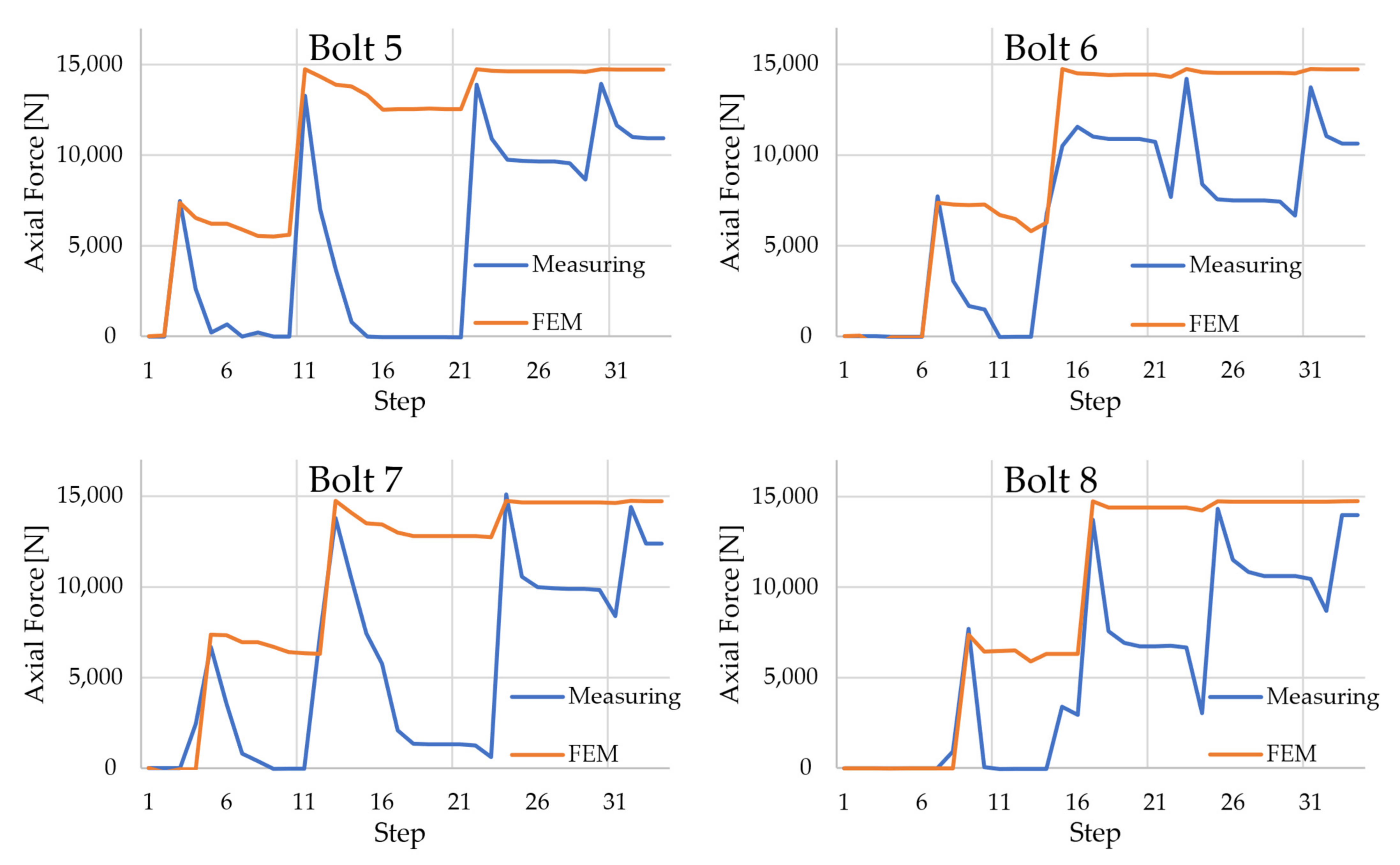
The difference in the values of the axial forces determined by the measurements and the FEM is best shown by the graphs in Figure 13. The graphical representation allows for the best visibility for each bolt individually. The values were inserted in 34 steps.
The difference between measured data and the FEM data is clear. It is clear from the graphs that the FEM data is much more uniform due to the exclusion of effects such as surface structure. The achieved axial force in the bolt at the tightening end is always lower in the case of measurement than in the case of FEM. The difference may also be due to the way the bolts are tightened, which is based on the tightening torque and not directly on the axial force in the bolt.

4. Conclusions

In conclusion, it can be concluded that even if the bolts are placed symmetrically around the axis of the sleeve and are tightened exactly according to the manufacturer’s catalog, the axial force in the bolts is not the same, and there is an asymmetry.
The asymmetry of the axial forces is created by several factors that enter the tightening process of the clamping sleeve bolts.
  • Tightening based on tightening torque. Since the tightening of the sleeve is based on the tightening torque, but the axial force in the bolts is measured and required, differences in frictional properties on individual bolts will cause different axial forces in individual bolts.
  • Tightening procedure according to the manufacturer’s catalog. The manufacturer’s catalog recommends tightening each bolt in sequence. From a practical perspective, the symmetrical simultaneous tightening of all bolts at the same time cannot be achieved. The only option would be to tighten with a specialized mechanical device.
  • Different friction properties and surface texture. All contact surfaces of the sleeve may have different frictional properties at different points. Differences cannot be detected, so they are neglected.
The solution to this problem could be part of further research. The best solution is to modify the tightening procedure so that the differences in axial forces between the individual bolts are as small as possible. It would be advantageous to use the FEM model to determine a better tightening procedure. It is faster and cheaper than bonded strain gauges on bolts. In addition, we can simulate the FEM with the original axial force in the bolts. A complication arises by not introducing some of the properties of the clamping sleeve. Not introducing the surface structure seems to be essential. The FEM model shows a relatively uniform distribution of axial forces between the bolts, although the response sleeve shows very different values of axial forces in the sleeve bolts.

Author Contributions

Conceptualization, L.H. and J.S.; data curation, L.H.; formal analysis, L.H.; investigation, L.H.; methodology, L.H. and J.S.; resources, L.H.; software, M.T.; supervision, J.Z.; validation, L.H., J.S., M.T. and J.Z.; visualization, L.H.; writing—original draft, L.H.; writing—review and editing, L.H. All authors have read and agreed to the published version of the manuscript.

Funding

This article was supported specifically by VSB Technical University of Ostrava, research number SP2023/077.

Data Availability Statement

The data presented in this study are available on request from the corresponding author.

Conflicts of Interest

The authors declare no conflict of interest.

References

  1. Kaláb, K.; František, O. Posudek Pevnosti, Tuhosti a Únosnosti Hřídele Hnacího Bubnu D830 Poháněcí Stanice Dopravníku BELT 1200; VŠB—TU Ostrava: Ostrava, Czech Republic, 2010. [Google Scholar]
  2. Kaláb, K.; František, O. Návrh a Posouzení Konstrukčních Úprav Hnacího Hřídele Dvoububnové Poháněcí Stanice 4 × 250 [KW] s Cílem Zlepšení Provozních Vlastností; VŠB—TU Ostrava: Ostrava, Czech Republic, 2010. [Google Scholar]
  3. Rexnord Tollok Locking Assemblies Catalog. Available online: https://www.rexnord.com/contentitems/techlibrary/documents/pt2-001m_a4_catalog (accessed on 24 May 2023).
  4. Lukáš, H. Analýza Vlastností Svěrných Spojů; VŠB—TU Ostrava: Ostrava, Czech Republic, 2022. [Google Scholar]
  5. Hashimura, S.; Komatsu, K.; Inoue, C.; Nakao, T. A New Tightening Method of Bolt/Nut Assembly to Control the Clamping Force. J. Adv. Mech. Des. Syst. Manuf. 2008, 2, 896–902. [Google Scholar] [CrossRef]
  6. Hashimura, S.; Sakai, H.; Kubota, K.; Ohmi, N.; Otsu, T.; Komatsu, K. Influence of Configuration Error in Bolted Joints on Detection Error of Clamp Force Detection Method. Int. J. Autom. Technol. 2021, 15, 396–403. [Google Scholar] [CrossRef]
  7. Yuan, S.; Zhang, Y.; Fan, Y.; Zhang, Y. A Method to Achieve Uniform Clamp Force in a Bolted Rotor with Curvic Couplings. Proc. Inst. Mech. Eng. Part E J. Process Mech. Eng. 2016, 230, 335–344. [Google Scholar] [CrossRef]
  8. Abid, M.; Hussain, S. Bolt Preload Scatter and Relaxation Behaviour during Tightening a 4 In-900# Flange Joint with Spiral Wound Gasket. Proc. Inst. Mech. Eng. Part E J. Process Mech. Eng. 2008, 222, 123–134. [Google Scholar] [CrossRef]
  9. Nassar, S.A.; Wu, Z.; Yang, X. Achieving Uniform Clamp Load in Gasketed Bolted Joints Using a Nonlinear Finite Element Model. J. Press. Vessel. Technol. Trans. ASME 2010, 132, 031205. [Google Scholar] [CrossRef]
  10. Abid, M.; Khan, A.; Nash, D.H.; Hussain, M.; Wajid, H.A. Simulation of Optimized Bolt Tightening Strategies for Gasketed Flanged Pipe Joints. Procedia Eng. 2015, 130, 204–213. [Google Scholar] [CrossRef]
  11. Zacal, J.; Pavlik, J.; Kunzova, I. Influence of shape of pressure vessel shell on bolt working load and tightness. MM Sci. J. 2021, 12, 5448–5451. [Google Scholar] [CrossRef]
  12. Bolt-Tightening Handbook. Linear Motion & Precision Technologies; Guide Du Serrage GB 11; The SKF Group: Singapore, 2001.
  13. VDI-Fachbereich Getriebe und Maschinenelemente. Systematische Berechnung Hochbeanspruchter Schraubenverbindungen—Mehrschraubenverbindungen (Systematic Calculation of Highly Stressed Bolted Joints Multi Bolted Joints); VDI 2230 Blatt 2/Part 2; VDI-Handbuch Produktentwicklung und Konstruktion: Düsseldorf, Germany, 2014. [Google Scholar]
  14. Grzejda, R. Impact of Nonlinearity on Bolt Forces in Multi-Bolted Joints: A Case of the Assembly Stage. Sci. Iran. 2019, 26, 1299–1306. [Google Scholar] [CrossRef]
  15. Grzejda, R. Non-Linearity of the Contact Layer between Elements Joined in a Multi-Bolted Connection and the Preload of the Bolts. Combust. Engines 2016, 165, 3–8. [Google Scholar] [CrossRef]
  16. Grzejda, R. Study of the Distribution of Bolt Forces in a Multi-Bolted System under Operational Normal Loads. In Proceedings of the AIP Conference Proceedings, Jora Wielka, Poland, 4 March 2019; American Institute of Physics Inc.: College Park, MD, USA, 2019; Volume 2078. [Google Scholar]
  17. Pospíšil, F. Závitová a Šroubová Spojení, 1st ed.; SNTL—Nakladatelství Technické Literatury: Praha, Czech Republic, 1968. [Google Scholar]
  18. VDI-Fachbereich Getriebe und Maschinenelemente. Systematische Berechnung hochbeanspruchter Schraubenverbindungen—Zylindrische Einschraubenverbindungen (Systematic Calculation of Highly Stressed Bolted Joints Joints with One Cylindrical Bolt); VDI 2230 Blatt 1; VDI-Handbuch Produktentwicklung und Konstruktion: Düsseldorf, Germany, 2015. [Google Scholar]
  19. Molnár, L.; Váradi, K.; Liktor, B. Stress Analysis of Bolted Joints Part I. Numerical Dimensioning Method. Mod. Mech. Eng. 2014, 4, 35–45. [Google Scholar] [CrossRef]
  20. Meisami, F.; Moavenian, M.; Afsharfard, A. Nonlinear Behavior of Single Bolted Flange Joints: A Novel Analytical Model. Eng. Struct. 2018, 173, 908–917. [Google Scholar] [CrossRef]
  21. Začal, J.; Folta, Z.; Jančar, L. Design of a sensor for measurement of bolt pretension. In Proceedings of the 58th International Conference of Machine Design Departments (ICMD), Prague, Czech Republic, 7–9 September 2017; pp. 426–429. [Google Scholar]
  22. Goldarag, F.E.; Barzegar, S.; Babaei, A. An experimental method for measuring the clamping force in double lap simple bolted and hybrid (bolted-bonded) joints. Trans. FAMENA 2015, 39, 87–94. [Google Scholar]
  23. Huang, Y.H.; Liu, L.; Yeung, T.W.; Hung, Y.Y. Real-Time Monitoring of Clamping Force of a Bolted Joint by Use of Automatic Digital Image Correlation. Opt. Laser Technol. 2009, 41, 408–414. [Google Scholar] [CrossRef]
  24. Oman, S.; Nagode, M. Bolted Connection of an End-Plate Cantilever Beam: The Distribution of Operating Force. Stroj. Vestn./J. Mech. Eng. 2017, 63, 617–627. [Google Scholar] [CrossRef]
  25. Hrcek, S.; Kohar, R.; Steininger, J. Axial Stiffness for Large-Scale Ball Slewing Rings with Four-Point Contact. Bull. Pol. Acad. Sci. 2021, 69, e136725. [Google Scholar]
  26. Zacal, J.; Folta, Z.; Struz, J.; Trochta, M. Influence of Symmetry of Tightened Parts on the Force in a Bolted Joint. Symmetry 2023, 15, 276. [Google Scholar] [CrossRef]
  27. Zhang, M.; Yang, M.; Li, P.; Gao, Y. Mechanical Behaviors of a Symmetrical Bolt Fasten Wedge Active Joint for Braced Excavations. Symmetry 2020, 12, 140. [Google Scholar] [CrossRef]
  28. Xiaolin, C.; Yijun, L. Finite Element Modeling and Simulation with ANSYS Workbench, version number: 20140707; Taylor & Francis Group, LLC: New York, NY, USA, 2015; ISBN-13: 978-1-4398-7385-4. [Google Scholar]
  29. Ning, K.; Wang, J.; Li, P.; Xiang, D.; Hou, D. Multi-Objective Intelligent Cooperative Design for Interference Fit of the Conical Sleeve. J. Mech. Sci. Technol. 2021, 35, 3569–3578. [Google Scholar] [CrossRef]
  30. Tian, Y.; Qian, H.; Cao, Z.; Zhang, D.; Jiang, D.; Lim, J.H.; Luongo, A. Identification of Pre-Tightening Torque Dependent Parameters for Empirical Modeling of Bolted Joints. Appl. Sci. 2021, 11, 9134. [Google Scholar] [CrossRef]
  31. Lukáš, H.; Jiří, S.; Květoslav, K. Experimental Determination of Changing the Axial Force in the Bolts of the Clamping Sleeve Under Its Axial Load. Stroj. Časopis—J. Mech. Eng. 2021, 71, 79–86. [Google Scholar] [CrossRef]
  32. Květoslav, K. Interaktivní a Multimediální PDF Části a Mechanismy Strojů—Teorie + Projekty. In E-Learning Systém; VŠB—TU: Ostrava, Czechia, 2018. [Google Scholar]
  33. HBM Test and Measurement Strain Gauge. Available online: https://www.hbm.com/fileadmin/mediapool/hbmdoc/technical/S01265.pdf (accessed on 29 August 2023).
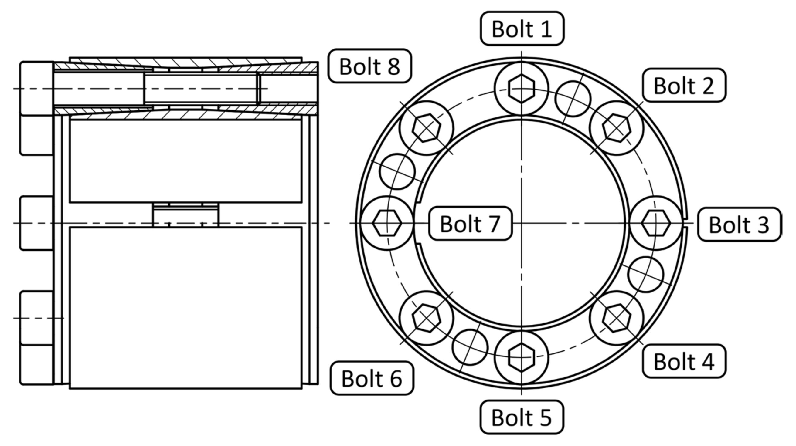
Figure 1. Clamping sleeve with numbered bolts.
Symmetry 15 01893 g001
Figure 2. Value of contact pressure acting on the shaft.
Symmetry 15 01893 g002
Figure 3. The value of the contact pressure acting on the hole in the hub.
Symmetry 15 01893 g003
Figure 4. Schematic representation of a bolt with strain gauges.
Symmetry 15 01893 g004
Figure 5. Bolt with bonded strain gauges.
Symmetry 15 01893 g005
Figure 6. Strain gauge calibration.
Symmetry 15 01893 g006
Figure 7. Hub and sleeve without shaft.
Symmetry 15 01893 g007
Figure 8. Bolt from FEM analysis.
Symmetry 15 01893 g008
Figure 9. Automatically generated mesh from ANSYS.
Symmetry 15 01893 g009
Figure 10. Modified mesh from ANSYS.
Symmetry 15 01893 g010
Figure 11. FEM model contacts. (a) Friction contacts between cones and sleeve rings. (b) Contact on cylindrical surfaces between sleeve rings and shaft or hub. (c) Contact between threaded cone and bolts. (d) Contact between cone and bolt head.
Symmetry 15 01893 g011
Figure 12. Boundary conditions of FEM analysis.
Symmetry 15 01893 g012
Figure 13. Measuring data and FEM data for each bolt.
Symmetry 15 01893 g013aSymmetry 15 01893 g013b
Table 1. Tightening moment and axial force in bolts.
Tightening MomentAxial Force
Tightening to half torque at the cross10 Nm ± 5%7368.7 N
Tightening to full torque at the cross20 Nm ± 5%14,707 N
First tightening around the perimeter to full torque20 Nm ± 5%14,707 N
Second tightening around the perimeter to full torque20 Nm ± 5%14,707 N
Table 2. Material properties.
Structural Steel
Density7850 kg/m3
Young’s Modulus2 × 105 MPa
Poisson’s Ratio0.3
Table 3. Bolt tightening procedure in FEM analysis.
Bolt 1 (N)Bolt 2 (N)Bolt 3 (N)Bolt 4 (N)Bolt 5 (N)Bolt 6 (N)Bolt 7 (N)Bolt 8 (N)
Step100000000Load
Step27369LockLockLockLockLockLockLockTightening to half torque at the cross
Step3LockLockLockLock7,368,695LockLockLock
Step4LockLock7369LockLockLockLockLock
Step5LockLockLockLockLockLock7369Lock
Step6Lock7369LockLockLockLockLockLock
Step7LockLockLockLockLock7369LockLock
Step8LockLockLock7369LockLockLockLock
Step9LockLockLockLockLockLockLock7369
Step1014,737LockLockLockLockLockLockLockTightening to full torque at the cross
Step11LockLockLockLock14,737LockLockLock
Step12LockLock14,737LockLockLockLockLock
Step13LockLockLockLockLockLock14,737Lock
Step14Lock14,737LockLockLockLockLockLock
Step15LockLockLockLockLock14,737LockLock
Step16LockLockLock14,737LockLockLockLock
Step17LockLockLockLockLockLockLock14,737
Step1814,737LockLockLockLockLockLockLockFirst tightening around the perimeter to full torque
Step19Lock14,737LockLockLockLockLockLock
Step20LockLock14,737LockLockLockLockLock
Step21LockLockLock14,737LockLockLockLock
Step22LockLockLockLock14,737LockLockLock
Step23LockLockLockLockLock14,737LockLock
Step24LockLockLockLockLockLock14,737Lock
Step25LockLockLockLockLockLockLock14,737
Step2614,737LockLockLockLockLockLockLockSecond tightening around the perimeter to full torque
Step27Lock14,737LockLockLockLockLockLock
Step28LockLock14,737LockLockLockLockLock
Step29LockLockLock14,737LockLockLockLock
Step30LockLockLockLock14,737LockLockLock
Step31LockLockLockLockLock14,737LockLock
Step32LockLockLockLockLockLock14,737Lock
Step33LockLockLockLockLockLockLock14,737
Step34LockLockLockLockLockLockLockLockFinal
Table 4. Axial forces in bolts determined by measurement.
Bolt 1
(N)
Bolt 2
(N)
Bolt 3
(N)
Bolt 4
(N)
Bolt 5
(N)
Bolt 6
(N)
Bolt 7
(N)
Bolt 8
(N)
Step100000000Load
Step27614.22−15.011.51−20.030.530.52−0.46−3.83Tightening to half torque at the cross
Step31419.11−4.12−2.53−25.677469.60−1.04−1.66−5.19
Step4−25.79−8.675121.02−33.292621.93−4.432454.08−8.51
Step5−18.15−15.715233.22−36.05213.74−4.596684.75−9.79
Step61451.005960.76190.332079.66657.57−5.723572.00−6.20
Step7−11.357503.16349.67−40.12−16.487704.75796.12−7.57
Step8−12.495020.45−16.566207.28209.123043.43392.01920.01
Step9−10.691698.68−10.197395.16−17.531687.88−22.027691.23
Step1012,953.71−29.03−0.535861.13−12.151473.39−7.6864.45Tightening to full torque at the cross
Step1111,942.56−23.56−1.20517.6013,264.32−26.64−9.82−53.06
Step126896.56−19.096882.55133.537004.06−17.237287.41−42.39
Step133699.63−15.7913,770.43−114.573697.45−13.6913,804.47−36.38
Step142799.033295.7210,732.943118.07780.516768.7810,586.55−31.82
Step1567.8811,495.777939.143056.720.9810,516.967443.023384.18
Step1678.3510,711.082967.7713,105.23−42.7311,566.625768.962928.16
Step17−28.2912,280.312011.3512,899.30−38.5811,017.442073.9013,712.97
Step1814,630.106128.271473.2612,746.89−38.1910,870.331343.017560.79First tightening around the perimeter to full torque
Step1910,785.0613,810.27518.2412,130.64−38.4110,878.841327.746899.88
Step209523.617882.1914,692.247110.66−39.6410,886.501325.746727.78
Step219488.867431.0312,030.8913,481.10−43.1910,725.941327.236736.22
Step229482.357384.0811,151.428646.5313,879.977677.901267.236743.12
Step239478.487362.4210,928.967696.6210,898.6814,188.13615.826656.81
Step249220.227367.4410,933.797609.449749.038406.4915,090.663042.15
Step256156.047191.9110,937.157603.049674.637546.0110,576.2414,308.60
Step2614,157.365714.8110,851.897605.779651.517496.549984.7911,514.25Second tightening around the perimeter to full torque
Step2711,017.2613,589.929156.777512.149653.367497.289922.2510,839.88
Step2810,148.2111,186.8114,247.016360.839559.497493.319889.8010,599.67
Step2910,117.8510,893.1512,619.0613,115.208656.107446.089886.5410,600.59
Step3010,103.1810,830.5612,259.7211,569.9713,936.856665.779826.0710,595.99
Step3110,094.6710,821.3412,199.1711,034.1011,650.8513,730.568389.0410,450.13
Step329946.8010,812.9212,187.0010,900.0010,991.4511,047.5914,394.548693.12
Step338722.7310,724.4312,182.1810,867.1510,935.0310,626.5112,394.7913,976.74
Step348722.7310,724.4312,182.1810,867.1510,935.0310,626.5112,394.7913,976.74Final
Table 5. Axial force in bolts from FEM analysis.
Bolt 1
(N)
Bolt 2
(N)
Bolt 3
(N)
Bolt 4
(N)
Bolt 5
(N)
Bolt 6
(N)
Bolt 7
(N)
Bolt 8
(N)
Step100000000Load
Step27368.69−12.60−202.7533.4571.8432.90−222.84−25.01Tightening to half torque at the cross
Step37313.40−12.61−16.43−504.337368.69−469.42−39.44−25.01
Step47027.10−12.637368.69−30.316551.30−42.40−39.45−25.02
Step56736.20−12.637432.20−30.326202.50−42.407368.69−25.01
Step66441.707368.697160.90−30.326209.70−42.407346.60−25.01
Step76383.607261.507114.40−30.325881.607368.696962.40−25.01
Step86414.507230.306860.907368.695529.907269.706947.10−25.02
Step96210.807169.206828.307330.605522.607240.006698.407368.69
Step1014,737.396265.606789.007420.305602.607256.206415.206432.50Tightening to full torque at the cross moment
Step1114,853.006194.906672.006816.2014,737.396705.006325.606456.60
Step1214,830.005423.6014,737.395846.3014,334.006480.806311.206512.50
Step1314,467.006164.6014,120.006376.5013,883.005811.5014,737.395876.40
Step1413,430.0014,737.3913,485.006376.5013,791.006271.1014,110.006311.20
Step1513,408.0014,746.0013,477.006376.5013,294.0014,737.3913,504.006312.90
Step1613,455.0014,643.0012,890.0014,737.3912,508.0014,500.0013,434.006312.90
Step1713,103.0014,571.0012,921.0014,783.0012,544.0014,457.0013,004.0014,737.39
Step1814,737.3914,368.0012,914.0014,796.0012,550.0014,418.0012,795.0014,404.00First tightening around the perimeter to full torque
Step1914,684.0014,737.3912,877.0014,792.0012,553.0014,424.0012,808.0014,383.00
Step2014,668.0014,550.0014,737.3914,671.0012,539.0014,431.0012,817.0014,391.00
Step2114,664.0014,529.0014,711.0014,737.3912,532.0014,430.0012,814.0014,388.00
Step2214,675.0014,541.0014,685.0014,582.0014,737.3914,297.0012,793.0014,398.00
Step2314,678.0014,543.0014,677.0014,532.0014,651.0014,737.3912,743.0014,394.00
Step2414,662.0014,558.0014,692.0014,542.0014,607.0014,549.0014,737.3914,240.00
Step2514,617.0014,550.0014,695.0014,546.0014,612.0014,527.0014,647.0014,737.39
Step2614,737.3914,539.0014,694.0014,545.0014,611.0014,527.0014,643.0014,721.00Second tightening around the perimeter to full torque
Step2714,711.0014,737.3914,680.0014,543.0014,608.0014,524.0014,642.0014,717.00
Step2814,711.0014,732.0014,737.3914,539.0014,608.0014,523.0014,641.0014,716.00
Step2914,712.0014,730.0014,725.0014,737.3914,596.0014,522.0014,642.0014,717.00
Step3014,712.0014,731.0014,723.0014,727.0014,737.3914,513.0014,641.0014,718.00
Step3114,713.0014,732.0014,724.0014,723.0014,720.0014,737.3914,624.0014,716.00
Step3214,712.0014,733.0014,724.0014,723.0014,715.0014,724.0014,737.3914,706.00
Step3314,710.0014,733.0014,725.0014,723.0014,715.0014,723.0014,733.0014,737.39
Step3414,710.0014,733.0014,725.0014,723.0014,715.0014,723.0014,732.0014,737.00Final
Disclaimer/Publisher’s Note: The statements, opinions and data contained in all publications are solely those of the individual author(s) and contributor(s) and not of MDPI and/or the editor(s). MDPI and/or the editor(s) disclaim responsibility for any injury to people or property resulting from any ideas, methods, instructions or products referred to in the content.