
A Compact Microwave Quadrature Hybrid Coupler Using Capacitive Composite Lines and Meandered Stubs

 ,
,  ,
,  ,
,  , , ,
, , , 
Abstract
:1. Introduction
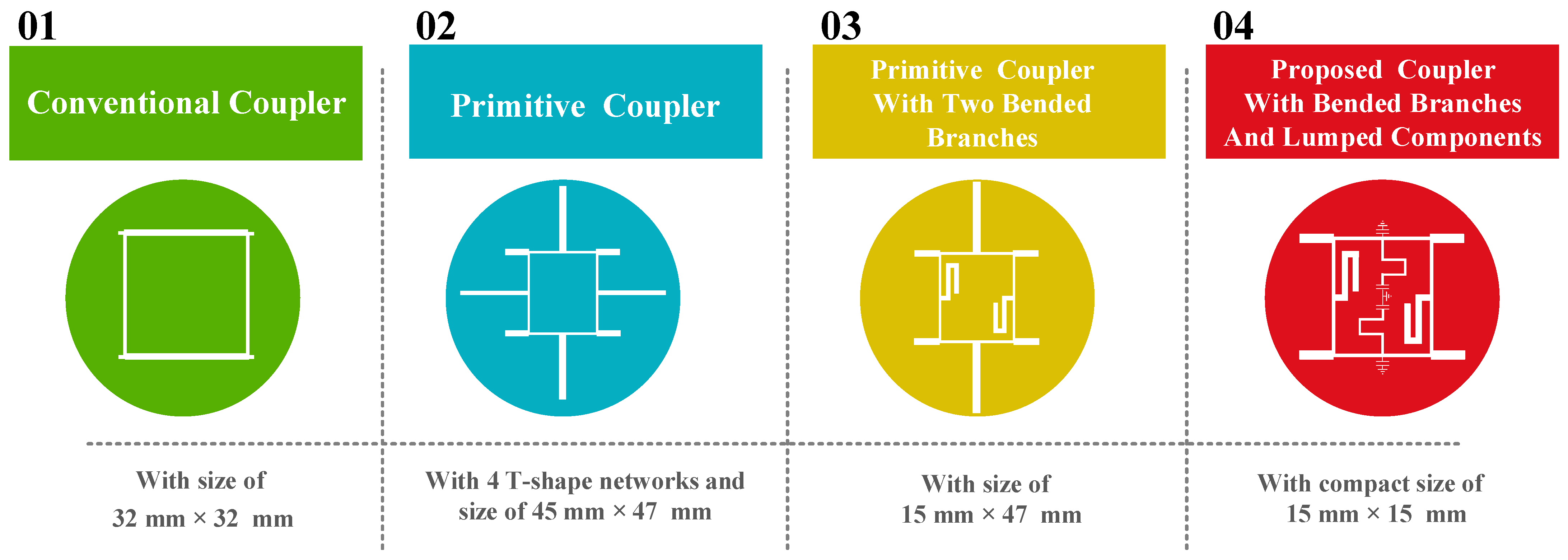
2. The Conventional 1600 MHz Quadrature Hybrid Coupler
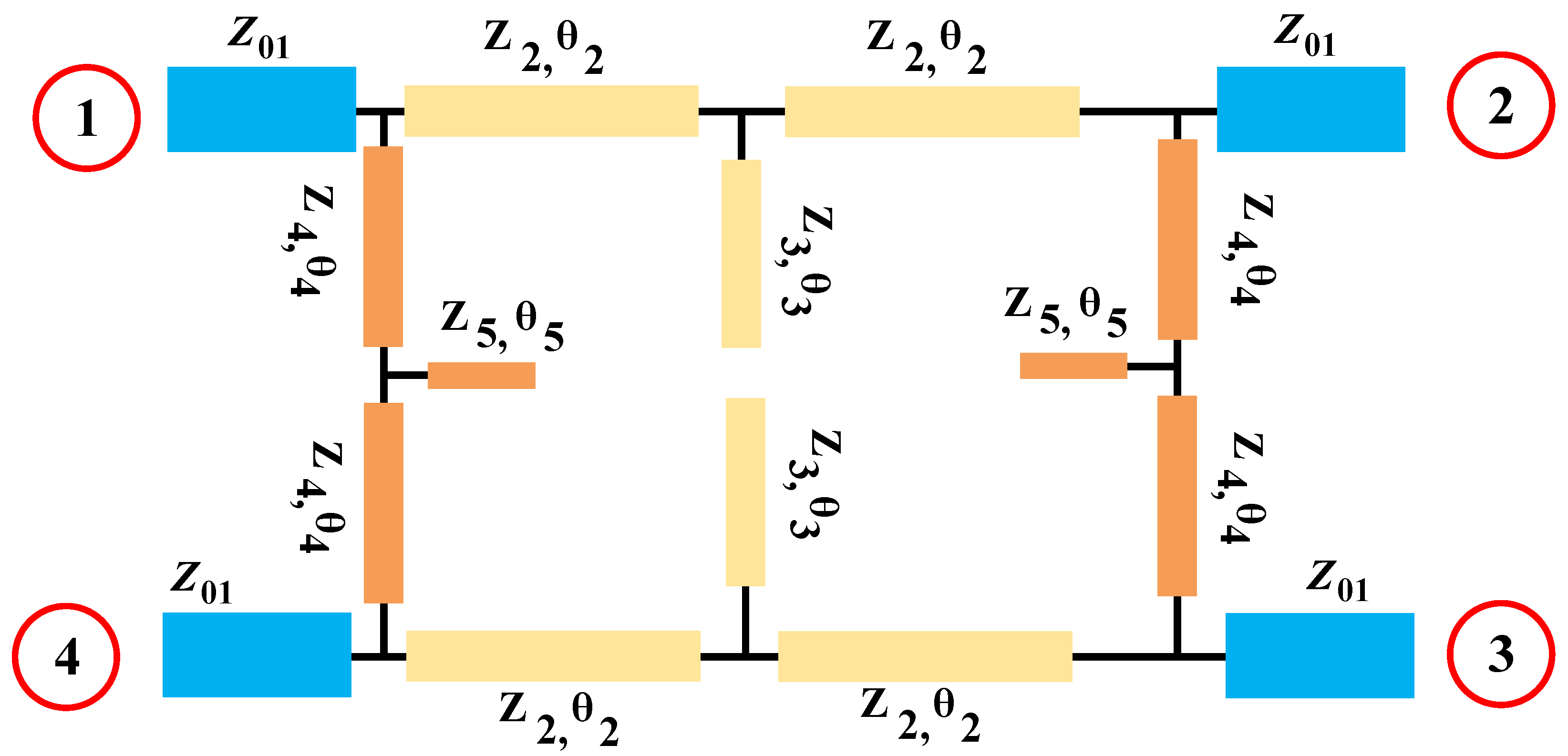
3. Design Process of the Primitive 1600 MHz Quadrature Hybrid Coupler with T-Shaped Branches
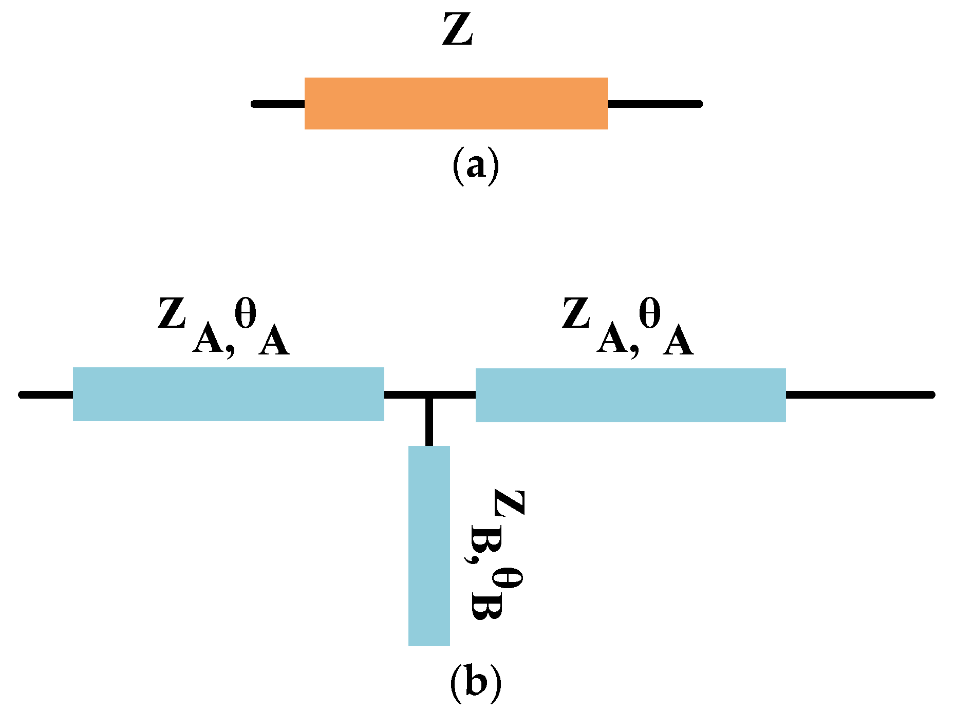
4. Design Process of the Primitive 1600 MHz Quadrature Hybrid Coupler with T-Shaped Branches and Bended Stubs
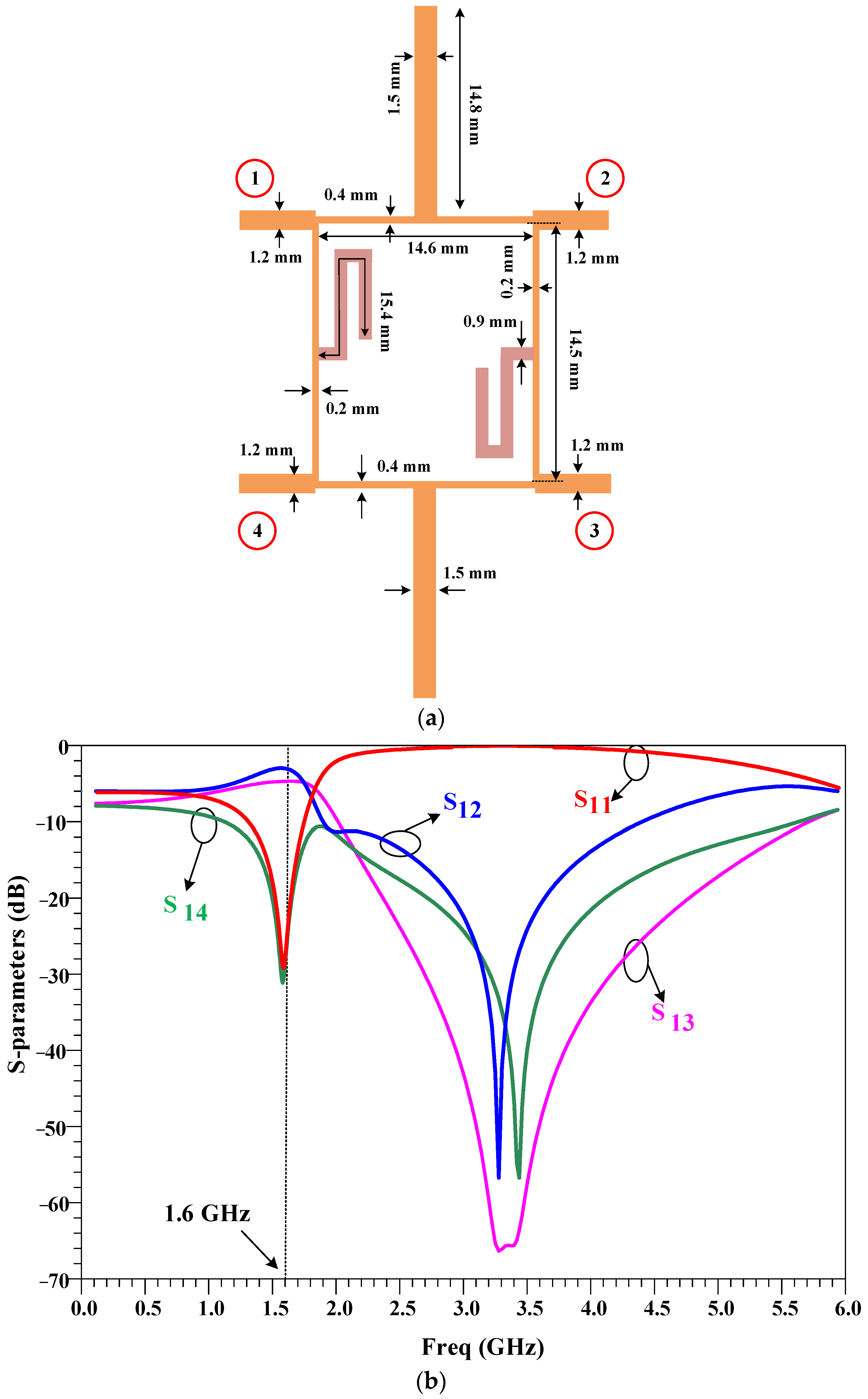
5. Design Process of the Proposed 1600 MHz Quadrature Hybrid Coupler
6. Conclusions
Author Contributions
Funding
Data Availability Statement
Conflicts of Interest
References
- Roshani, S.; Yahya, S.I.; Roshani, S.; Farahmand, A.H.; Hemmati, S. Design of a modified compact coupler with unwanted harmonics suppression for L-band applications. Electronics 2022, 11, 1747. [Google Scholar] [CrossRef]
- Roshani, S.; Yahya, S.I.; Roshani, S.; Rostami, M. Design and fabrication of a compact branch-line coupler using resonators with wide harmonics suppression band. Electronics 2022, 11, 793. [Google Scholar] [CrossRef]
- Alizadeh, S.; Roshani, S.; Roshani, S. A modified branch line coupler with compact size and ultra wide harmonics suppression band. Electromagnetics 2022, 42, 377–387. [Google Scholar] [CrossRef]
- Arigong, B.; Zhou, M.; Ren, H.; Chen, C.; Zhang, H. A Compact Lumped-Component Coupler with Tunable Coupling Ratios and Reconfigurable Responses. In Proceedings of the 2018 IEEE/MTT-S International Microwave Symposium-IMS, Philadelphia, PA, USA, 10–15 June 2018; IEEE: Piscataway, NJ, USA, 2018. [Google Scholar]
- Beigizadeh, M.; Dehghani, R.; Nabavi, A. Analysis and design of a lumped-element hybrid coupler using limited quality factor of components. AEU-Int. J. Electron. Commun. 2017, 82, 312–320. [Google Scholar] [CrossRef]
- Chen, Z.; Wu, Y.; Yang, Y.; Wang, W. A novel unequal lumped-element coupler with arbitrary phase differences and arbitrary impedance matching. IEEE Trans. Circuits Syst. II Express Briefs 2021, 69, 369–373. [Google Scholar] [CrossRef]
- Vogel, R.W. Analysis and design of lumped-and lumped-distributed-element directional couplers for MIC and MMIC applications. IEEE Trans. Microw. Theory Tech. 1992, 40, 253–262. [Google Scholar] [CrossRef]
- Roshani, S.; Yahya, S.I.; Alameri, B.M.; Mezaal, Y.S.; Liu, L.W.; Roshani, S. Filtering power divider design using resonant LC branches for 5G low-band applications. Sustainability 2022, 14, 12291. [Google Scholar] [CrossRef]
- Barik, R.K.; Koziel, S.; Bernhardsson, E. Design of Frequency-Reconfigurable Branch-Line Crossover Using Rectangular Dielectric Channels. IEEE Access 2023, 11, 38072–38081. [Google Scholar] [CrossRef]
- Wang, D.; Song, J.; Li, X.; Qin, Q.; Sun, L. Design of wideband and compact lumped-element couplers for 5G communication. In Proceedings of the 2020 IEEE 6th International Conference on Computer and Communications (ICCC), Chengdu, China, 11–14 December 2020; IEEE: Piscataway, NJ, USA, 2020. [Google Scholar]
- Kumar, K.P.; Karthikeyan, S. Wideband three section branch line coupler using triple open complementary split ring resonator and open stubs. AEU-Int. J. Electron. Commun. 2015, 69, 1412–1416. [Google Scholar] [CrossRef]
- Chang, W.-L.; Huang, T.-Y.; Shen, T.-M.; Chen, B.-C.; Wu, R.-B. Design of compact branch-line coupler with coupled resonators. In Proceedings of the 2007 Asia-Pacific Microwave Conference, Bangkok, Thailand, 11–14 December 2007; IEEE: Piscataway, NJ, USA, 2007. [Google Scholar]
- Lu, K.; Wang, G.-M.; Zhang, C.-X.; Wang, Y.-W. Design of miniaturized branch-line coupler based on novel spiral-based resonators. J. Electromagn. Waves Appl. 2011, 25, 2244–2253. [Google Scholar] [CrossRef]
- Lin, T.-W.; Lin, C.-H.; Huang, K.-C.; Kuo, J.-T. Compact branch-line coupler filter with transmission zeros. In Proceedings of the 2015 Asia-Pacific Microwave Conference (APMC), Nanjing, China, 6–9 December 2015; IEEE: Piscataway, NJ, USA, 2015. [Google Scholar]
- Ghaffarian, M.S.; Moradi, G.; Khajehpour, S.; Honari, M.M.; Mirzavand, R. Dual-band/dual-mode rat-race/branch-line coupler using split ring resonators. Electronics 2021, 10, 1812. [Google Scholar] [CrossRef]
- Niu, J.X.; Zhou, X.L. A novel dual-band branch line coupler based on strip-shaped complementary split ring resonators. Microw. Opt. Technol. Lett. 2007, 49, 2859–2862. [Google Scholar] [CrossRef]
- Al-Khateeb, L. Miniaturized hybrid branch line couplers based on a square-split resonator loading technique. Prog. Electromagn. Res. Lett. 2013, 40, 153–162. [Google Scholar] [CrossRef]
- Safia, O.A.; Talbi, L.; Hettak, K. A new type of transmission line-based metamaterial resonator and its implementation in original applications. IEEE Trans. Magn. 2013, 49, 968–973. [Google Scholar] [CrossRef]
- Yahya, S.I.; Rezaei, A.; Khaleel, Y.A. Design and Analysis of a Wide Stopband Microstrip Dual-band Bandpass Filter. ARO-Sci. J. Koya Univ. 2021, 9, 83–90. [Google Scholar] [CrossRef]
- Yahya, S.I.; Rezaei, A. Design and Fabrication of a Novel Ultra Compact Microstrip Diplexer Using Interdigital and Spiral Cells. ARO-Sci. J. Koya Univ. 2021, 9, 103–108. [Google Scholar] [CrossRef]
- Nouri, L.; Yahya, S.I.; Rezaei, A.; Hazzazi, F.A.; Nhu, B.N. A Compact Negative Group Delay Microstrip Diplexer with Low Losses for 5G Applications. Aro-Sci. J. Koya Univ. 2023, 11, 17–24. [Google Scholar] [CrossRef]
- Azadi, R.; Roshani, S.; Nosratpour, A.; Lalbakhsh, A.; Mozaffari, M.H. Half-elliptical resonator lowpass filter with a wide stopband for low band 5G communication systems. Electronics 2021, 10, 2916. [Google Scholar] [CrossRef]
- Golestanifar, A.; Karimi, G.; Lalbakhsh, A. Varactor-tuned wideband band-pass filter for 5G NR frequency bands n77, n79 and 5G Wi-Fi. Sci. Rep. 2022, 12, 16330. [Google Scholar] [CrossRef] [PubMed]
- Jamshidi, M.; Lalbakhsh, A.; Lotfi, S.; Siahkamari, H.; Mohamadzade, B.; Jalilian, J. A neuro-based approach to designing a Wilkinson power divider. Int. J. RF Microw. Comput. Aided Eng. 2020, 30, e22091. [Google Scholar] [CrossRef]
- Lalbakhsh, A.; Afzal, M.U.; Esselle, K.P.; Smith, S.L. All-metal wideband frequency-selective surface bandpass filter for TE and TM polarizations. IEEE Trans. Antennas Propag. 2022, 70, 2790–2800. [Google Scholar] [CrossRef]
- Lalbakhsh, A.; Alizadeh, S.M.; Ghaderi, A.; Golestanifar, A.; Mohamadzade, B.; Jamshidi, M.; Mandal, K.; Mohyuddin, W. A design of a dual-band bandpass filter based on modal analysis for modern communication systems. Electronics 2020, 9, 1770. [Google Scholar] [CrossRef]
- Lalbakhsh, A.; Ghaderi, A.; Mohyuddin, W.; Simorangkir, R.B.; Bayat-Makou, N.; Ahmad, M.S.; Lee, G.H.; Kim, K.W. A compact C-band bandpass filter with an adjustable dual-band suitable for satellite communication systems. Electronics 2020, 9, 1088. [Google Scholar] [CrossRef]
- Moloudian, G.; Soltani, S.; Bahrami, S.; Buckley, J.L.; O’Flynn, B.; Lalbakhsh, A. Design and fabrication of a Wilkinson power divider with harmonic suppression for LTE and GSM applications. Sci. Rep. 2023, 13, 4246. [Google Scholar] [CrossRef]
- Pradhan, N.C.; Koziel, S.; Barik, R.K.; Pietrenko-Dabrowska, A.; Karthikeyan, S.S. Miniaturized Dual-Band SIW-Based Bandpass Filters Using Open-Loop Ring Resonators. Electronics 2023, 12, 3974. [Google Scholar] [CrossRef]
- Koziel, S.; Haq, T. Uncertainty quantification of additive manufacturing post-fabrication tuning of resonator-based microwave sensors. Measurement 2023, 216, 112952. [Google Scholar] [CrossRef]
- Haq, T.; Koziel, S. Rapid design optimization and calibration of microwave sensors based on equivalent complementary resonators for high sensitivity and low fabrication tolerance. Sensors 2023, 23, 1044. [Google Scholar] [CrossRef]
- Tang, C.-W.; Chen, M.-G.; Lin, Y.-S.; Wu, J.-W. Broadband microstrip branch-line coupler with defected ground structure. Electron. Lett. 2006, 42, 1458–1460. [Google Scholar] [CrossRef]
- Kim, J.-S.; Kong, K.-B. Compact branch-line coupler for harmonic suppression. Prog. Electromagn. Res. C 2010, 16, 233–239. [Google Scholar] [CrossRef]
- Lim, J.-S.; Kim, C.-S.; Park, J.-S.; Ahn, D.; Nam, S. Design of 10 dB 90 branch line coupler using microstrip line with defected ground structure. Electron. Lett. 2000, 36, 1784–1785. [Google Scholar] [CrossRef]
- Kim, C.-S.; Lim, J.-S.; Park, J.-S.; Ahn, D.; Nam, S. A 10dB branch line coupler using defected ground structure. In Proceedings of the 2000 30th European Microwave Conference, Paris, France, 2–5 October 2000; IEEE: Piscataway, NJ, USA, 2000. [Google Scholar]
- Parandin, F.; Heidari, F.; Rahimi, Z.; Olyaee, S. Two-Dimensional photonic crystal Biosensors: A review. Opt. Laser Technol. 2021, 144, 107397. [Google Scholar] [CrossRef]
- Parandin, F.; Sheykhian, A. Design and simulation of a 2 × 1 All-Optical multiplexer based on photonic crystals. Opt. Laser Technol. 2022, 151, 108021. [Google Scholar] [CrossRef]
- Parandin, F. Ultra-compact terahertz all-optical logic comparator on GaAs photonic crystal platform. Opt. Laser Technol. 2021, 144, 107399. [Google Scholar] [CrossRef]
- Parandin, F.; Kamarian, R.; Jomour, M. A novel design of all optical half-subtractor using a square lattice photonic crystals. Opt. Quantum Electron. 2021, 53, 114. [Google Scholar] [CrossRef]
- Wei, F.; Chen, L.; Guo, Y.; Li, W.; Shi, X. Compact UWB directional coupler with one notch-band. J. Electromagn. Waves Appl. 2013, 27, 599–604. [Google Scholar] [CrossRef]
- Roshani, S.; Koziel, S.; Yahya, S.I.; Chaudhary, M.A.; Ghadi, Y.Y.; Roshani, S.; Golunski, L. Mutual Coupling Reduction in Antenna Arrays Using Artificial Intelligence Approach and Inverse Neural Network Surrogates. Sensors 2023, 23, 7089. [Google Scholar] [CrossRef]
- Calik, N.; Güneş, F.; Koziel, S.; Pietrenko-Dabrowska, A.; Belen, M.A.; Mahouti, P. Deep-learning-based precise characterization of microwave transistors using fully-automated regression surrogates. Sci. Rep. 2023, 13, 1445. [Google Scholar] [CrossRef]
- Alibakhshikenari, M.; Ali, E.M.; Soruri, M.; Dalarsson, M.; Naser-Moghadasi, M.; Virdee, B.S.; Stefanovic, C.; Pietrenko-Dabrowska, A.; Koziel, S.; Szczepanski, S. A comprehensive survey on antennas on-chip based on metamaterial, metasurface, and substrate integrated waveguide principles for millimeter-waves and terahertz integrated circuits and systems. IEEE Access 2022, 10, 3668–3692. [Google Scholar] [CrossRef]
- Alibakhshikenari, M.; Virdee, B.S.; Benetatos, H.; Ali, E.M.; Soruri, M.; Dalarsson, M.; Naser-Moghadasi, M.; See, C.H.; Pietrenko-Dabrowska, A.; Koziel, S. An innovative antenna array with high inter element isolation for sub-6 GHz 5G MIMO communication systems. Sci. Rep. 2022, 12, 7907. [Google Scholar] [CrossRef]
- Roshani, S.; Shahveisi, H. Mutual coupling reduction in microstrip patch antenna arrays using simple microstrip resonator. Wirel. Pers. Commun. 2022, 126, 1665–1677. [Google Scholar] [CrossRef]
- Khan, A.; Bashir, S.; Ghafoor, S.; Rmili, H.; Mirza, J.; Ahmad, A. Isolation Enhancement in a Compact Four-Element MIMO Antenna for Ultra-Wideband Applications. Cmc-Comput. Mater. Contin. 2023, 75, 911–925. [Google Scholar]
- Khan, A.; Bashir, S.; Ghafoor, S.; Qureshi, K.K. Mutual coupling reduction using ground stub and EBG in a compact wideband MIMO-antenna. IEEE Access 2021, 9, 40972–40979. [Google Scholar] [CrossRef]
- Abouhssous, K.; Zugari, A.; Zakriti, A. A compact microstrip coupler using T-shape and open stubs for fifth generation applications. In E3S Web of Conferences; EDP Sciences: Ulys, France, 2022. [Google Scholar]
- Chang, W.I.; Chung, M.J.; Park, C.S. Compact High-Directivity Contra-Directional Coupler. Electronics 2022, 11, 4115. [Google Scholar] [CrossRef]
- Barik, R.K.; Koziel, S.; Szczepanski, S. Wideband highly-selective bandpass filtering branch-line coupler. IEEE Access 2022, 10, 20832–20838. [Google Scholar] [CrossRef]
- Parsaei, K.; Keshavarz, R.; Boroujeni, R.M.; Shariati, N. Compact Pixelated Microstrip Forward Broadside Coupler Using Binary Particle Swarm Optimization. IEEE Trans. Circuits Syst. I: Regul. Pap. 2023, 1–10. [Google Scholar] [CrossRef]
- Tayebi, A.; Zarifi, D. On the miniaturization of microstrip ring-hybrid couplers using Gielis supershapes. IETE J. Res. 2023, 69, 1160–1165. [Google Scholar] [CrossRef]
- Li, C.; Ma, Z.-H.; Chen, J.-X.; Wang, M.-N.; Huang, J.-M. Design of a Compact Ultra-Wideband Microstrip Bandpass Filter. Electronics 2023, 12, 1728. [Google Scholar] [CrossRef]
- El-Rahman, A.; Sherine, I.; Ibrahim, K.M.; Attiya, A.M. A Dual-Band Rat Race Coupler for WLAN Applications. Int. J. Microw. Opt. Technol. 2023, 18, 473–480. [Google Scholar]
- Krishna, I.S.; Barik, R.K.; Karthikeyan, S.; Kokil, P. A miniaturized harmonic suppressed 3 dB branch line coupler using H-shaped microstrip line. Microw. Opt. Technol. Lett. 2017, 59, 913–918. [Google Scholar] [CrossRef]
- Chen, C.-F.; Chang, S.-F.; Tseng, B.-H. Compact microstrip dual-band quadrature coupler based on coupled-resonator technique. IEEE Microw. Wirel. Compon. Lett. 2016, 26, 487–489. [Google Scholar] [CrossRef]
- Reshma, S.; Mandal, M.K. Miniaturization of a 90° hybrid coupler with improved bandwidth performance. IEEE Microw. Wirel. Compon. Lett. 2016, 26, 891–893. [Google Scholar] [CrossRef]
- Nie, W.; Luo, S.; Guo, Y.-X.; Fan, Y. Miniaturized rat-race coupler with harmonic suppression. IEEE Microw. Wirel. Compon. Lett. 2014, 24, 754–756. [Google Scholar] [CrossRef]
- Wang, W.-H.; Shen, T.-M.; Huang, T.-Y.; Wu, R.-B. Miniaturized rat-race coupler with bandpass response and good stopband rejection. In Proceedings of the 2009 IEEE MTT-S International Microwave Symposium Digest, Boston, MA, USA, 7–12 June 2009; IEEE: Piscataway, NJ, USA, 2009. [Google Scholar]


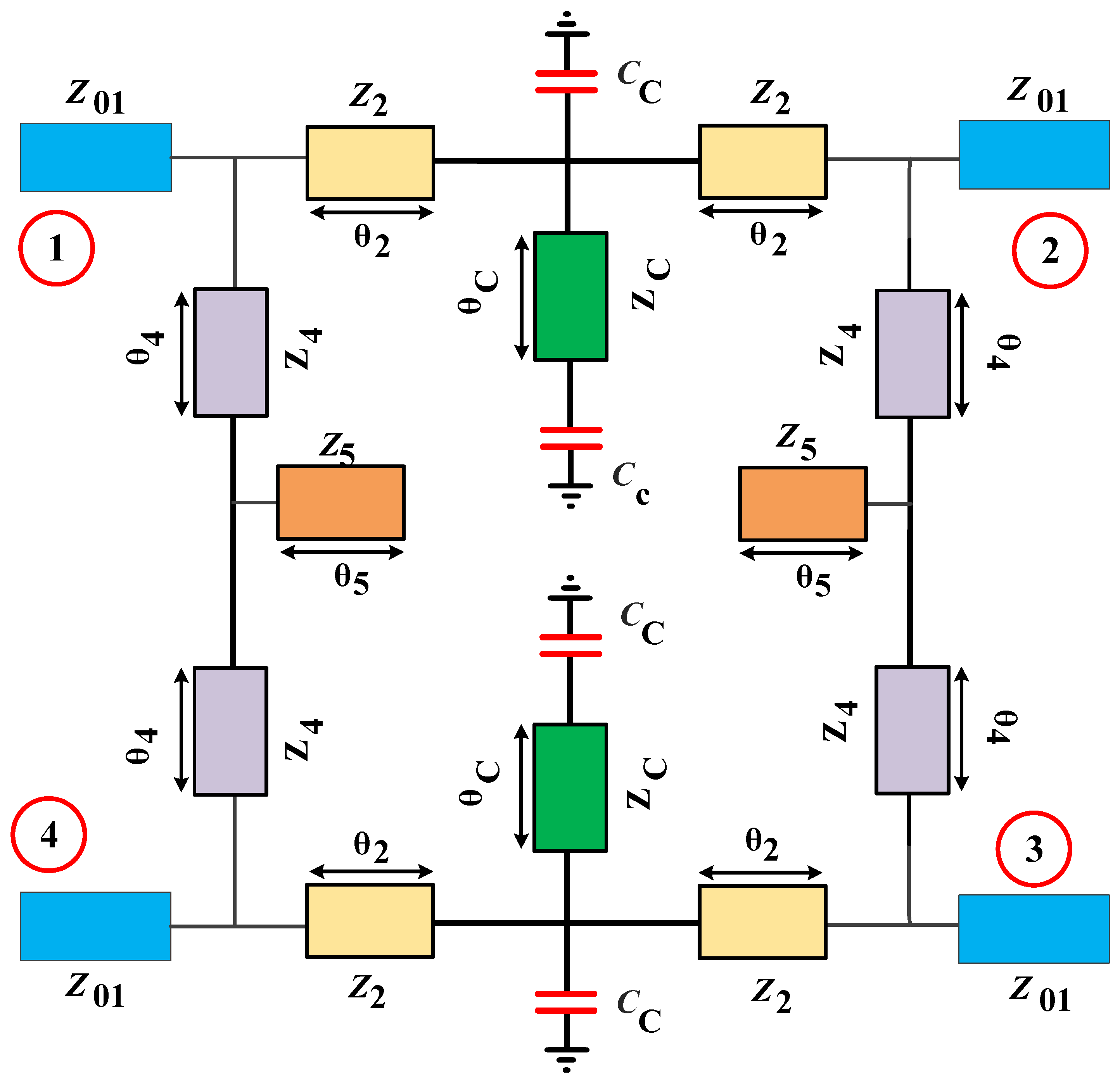
| Parameter | Z01 | Z2 | Z3 | Z4 | Z5 | θ2 | θ3 | θ4 | θ5 |
|---|---|---|---|---|---|---|---|---|---|
| Value | 50 Ω | 84 Ω | 42 Ω | 120 Ω | 60 Ω | 22.5⁰ | 45⁰ | 22.5⁰ | 45⁰ |
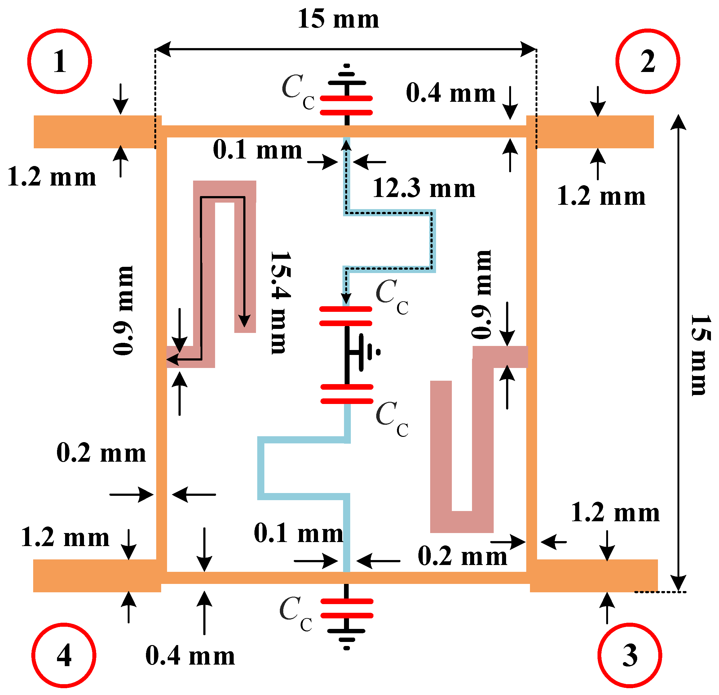
| L (mm) | 5 | 7.5 | 15.25 | 7.5 | 15.6 | 7.5 | 15.5 | 7.5 | 15.5 |
| W (mm) | 1.2 | 0.4 | 1.5 | 0.2 | 0.9 | - | - | - | - |
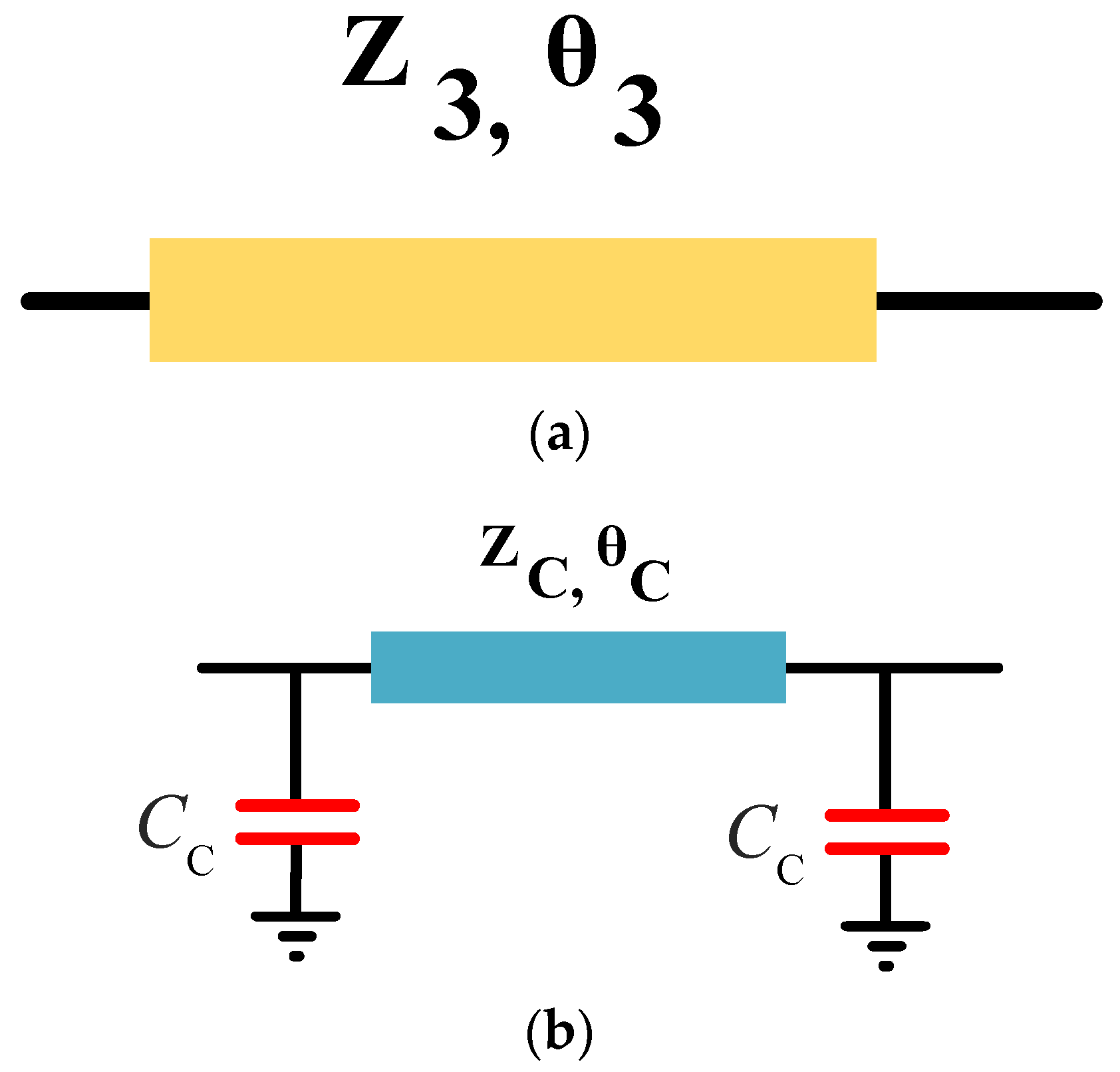
| Parameters | Zc | Cc | θc |
|---|---|---|---|
| values | 140 (Ω) | 0.5 (pF) | 36⁰ |
| Ref. | Operation Frequency (GHz) | Return Loss (dB) | Isolation (dB) | Insertion Loss (dB) | Phase Difference (Degree) | Size Reduction | Bandwidth (MHZ) | FBW | Applied Method |
|---|---|---|---|---|---|---|---|---|---|
| [55] | 0.9 | 28 | 28 | 0.26 | 90 ± 0.3 | 64% | 180 | 20% | H-shaped Lines |
| [56] | 1.6/2.1 | 21 | 24 | 2.4 | 90 ± 2.8/90 ± 4.5 | - | 150/300 | 9%/14% | Coupled Resonators |
| [57] | 1 | 31 | 26 | 0.6 | 90 ± 1.2 | 67% | 124 | 12.4% | Coupled Lines |
| [58] | 2.4 | 20 | 20 | 0.4 | 0 ± 1.4 | 70% | 650 | 27% | Open Stubs |
| [59] | 2 | 17 | 32 | 1.4 | 0 ± 0.9 | 49% | 110 | 5% | Coupled Resonator |
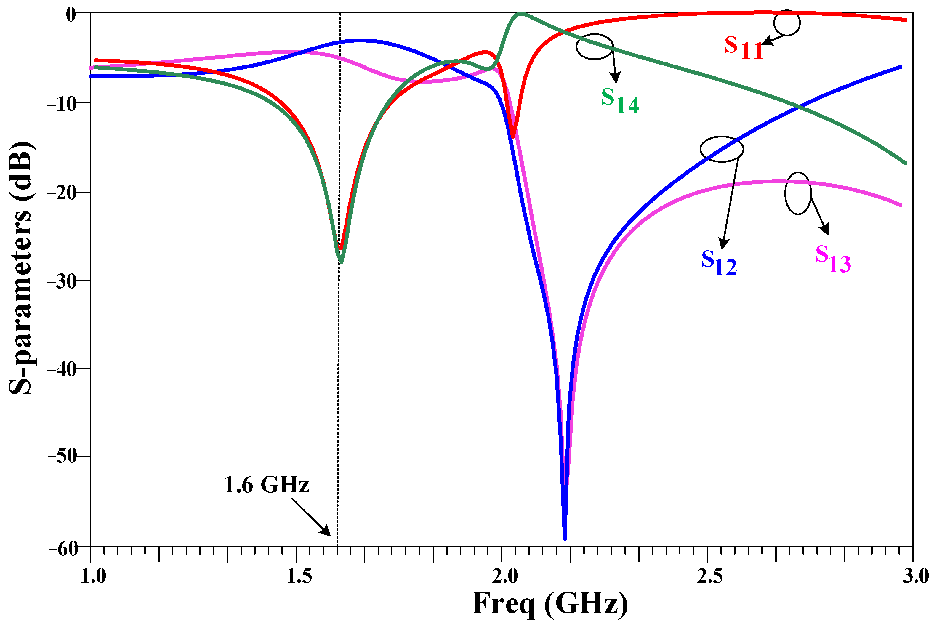
| This work | 1.6 | 27 | 28 | 0.4 | 90 ± 0.1 | 78% | 400 | 25% | Lumped Elements and Meandered Lines |
Disclaimer/Publisher’s Note: The statements, opinions and data contained in all publications are solely those of the individual author(s) and contributor(s) and not of MDPI and/or the editor(s). MDPI and/or the editor(s) disclaim responsibility for any injury to people or property resulting from any ideas, methods, instructions or products referred to in the content. |
© 2023 by the authors. Licensee MDPI, Basel, Switzerland. This article is an open access article distributed under the terms and conditions of the Creative Commons Attribution (CC BY) license (https://creativecommons.org/licenses/by/4.0/).
Share and Cite
Roshani, S.; Yahya, S.I.; Assaad, M.; Chaudhary, M.A.; Hazzazi, F.; Ghadi, Y.Y.; Ali, S.M.; Roshani, S. A Compact Microwave Quadrature Hybrid Coupler Using Capacitive Composite Lines and Meandered Stubs. Symmetry 2023, 15, 2149. https://doi.org/10.3390/sym15122149
Roshani S, Yahya SI, Assaad M, Chaudhary MA, Hazzazi F, Ghadi YY, Ali SM, Roshani S. A Compact Microwave Quadrature Hybrid Coupler Using Capacitive Composite Lines and Meandered Stubs. Symmetry. 2023; 15(12):2149. https://doi.org/10.3390/sym15122149
Chicago/Turabian StyleRoshani, Sobhan, Salah I. Yahya, Maher Assaad, Muhammad Akmal Chaudhary, Fawwaz Hazzazi, Yazeed Yasin Ghadi, Sarmad M. Ali, and Saeed Roshani. 2023. "A Compact Microwave Quadrature Hybrid Coupler Using Capacitive Composite Lines and Meandered Stubs" Symmetry 15, no. 12: 2149. https://doi.org/10.3390/sym15122149
APA StyleRoshani, S., Yahya, S. I., Assaad, M., Chaudhary, M. A., Hazzazi, F., Ghadi, Y. Y., Ali, S. M., & Roshani, S. (2023). A Compact Microwave Quadrature Hybrid Coupler Using Capacitive Composite Lines and Meandered Stubs. Symmetry, 15(12), 2149. https://doi.org/10.3390/sym15122149