Article

A Compact Microwave Quadrature Hybrid Coupler Using Capacitive Composite Lines and Meandered Stubs

1
Department of Electrical Engineering, Kermanshah Branch, Islamic Azad University, Kermanshah 6718997551, Iran
2
Department of Communication and Computer Engineering, Cihan University-Erbil, Erbil 44001, Iraq
3
Department of Software Engineering, Faculty of Engineering, Koya University, Koya 46017, Iraq
4
Department of Electrical and Computer Engineering, College of Engineering and Information Technology, Ajman University, Ajman 346, United Arab Emirates
5
Department of Electrical Engineering, College of Engineering in Al-Kharj, Prince Sattam bin Abdulaziz University, Al Kharj 11492, Saudi Arabia
6
Software Engineering and Computer Science Department, Al Ain University, Al Ain P.O. Box 15551, United Arab Emirates
*
Author to whom correspondence should be addressed.
Symmetry 2023, 15(12), 2149; https://doi.org/10.3390/sym15122149
Submission received: 12 October 2023 / Revised: 6 November 2023 / Accepted: 1 December 2023 / Published: 3 December 2023
(This article belongs to the Special Issue Symmetry/Asymmetry in Wireless Communication and Sensor Networks II)

Abstract

:
In this paper, a new structure of the quadrature hybrid coupler (QHC) with compact size is proposed using capacitive composite lines and meandered open stubs. The proposed coupler works at 1.6 GHz with a 0.4 GHz bandwidth, which shows 25% fractional bandwidth (FBW). The proposed QHC occupies only 15 mm × 15 mm (0.12 λ × 0.12 λ), while the typical QHC size is 32 mm × 32 mm (0.25 λ × 25 λ) at the same working frequency. In the designed structure, two symmetric meandered stubs and two symmetric π-shaped composite networks including capacitors and microstrip lines are applied together. The designed QHC has a small size and occupies only 22% of the area of the conventional QHC, resulting in a 78% size reduction. The designed prototype has been analyzed, fabricated and tested, and the experimental results verify the simulated and analysis results. The results show a better than 27 dB return loss, more than 28 dB isolation between the output ports and less than 0.4 dB insertion loss at the working frequency of 1600 MHz. With the achieved desirable specifications, the fabricated QHC is a suitable choice for wireless microwave applications.

1. Introduction

Microstrip quadrature hybrid couplers (QHCs) are passive devices, which are widely used in communications and radio frequency (RF) systems to split or combine signals. They divide an incident signal into two output signals with a 90-degree phase difference [1]. QHCs have numerous benefits, such as high isolation, low insertion loss, and excellent phase and amplitude balance. The high isolation of quadrature hybrid couplers allows them to separate signals without interference, which is particularly important in RF systems, where multiple signals need to be transmitted and received. Additionally, the low insertion loss of quadrature hybrid couplers ensures that minimal power is lost during signal transmission, resulting in improved system efficiency [2]. The conventional quadrature hybrid coupler includes four bulky quarter-wavelength lines, occupying a large area. Recently, several works have been introduced to design couplers with a small size using different methods [3].
Utilizing LC (inductance–capacitance) components in QHCs is a common strategy for enhancing their performance [4,5,6,7]. These passive devices are integral in microwave and RF systems, facilitating power division and signal combining tasks. By incorporating carefully designed inductors and capacitors into the QHC architecture, several advantages can be achieved. LC components allow for precise impedance matching, ensuring minimal signal reflection and optimal power transfer. Moreover, they enable broader bandwidth capabilities, enabling these couplers to operate effectively over a wider range of frequencies with wide suppression band. The addition of inductors and capacitors also contributes to improve the isolation between the input and output ports, reducing unwanted signal coupling [8,9]. In [10], by using LC components, a compact size co-directional coupler was obtained. In [5], a hybrid coupler was designed with LC elements to design a coupler at 3 GHz with minimized input return loss by adjusting the quality factor of each element. A coupler with lumped elements is presented in [6] to obtain arbitrary performances, such as the power division ratio, phase, and impedance matching.
Incorporating resonators and open stubs within QHCs is another strategy to enhance their performance in RF and microwave systems. Resonators, designed to operate at specific frequencies, can be integrated into the QHC structure to introduce frequency-selective properties. By carefully tuning these resonators, it becomes possible to achieve narrowband filtering functions within the coupler, facilitating signal separation or channelization. On the other hand, open stubs have been used to fine-tune the QHC impedance and phase characteristics, offering control over the power division and output isolation. In essence, the combination of resonators and open stubs in couplers make it possible to design couplers with desirable parameters, such as compact size, bandwidth selectivity and desirable suppression band. A wide band coupler was designed in [11] using triple ring resonators and open stubs, which can provide a 53% operating bandwidth. A compact size was achieved in the designed coupler in [12], using coupler resonators in the structure of the conventional coupler. In addition, other types of resonators, such as spiral ring resonators [13], half-wave resonator [14], split ring resonators [15,16,17] and metamaterial resonators [18] have been used to improve the QHCs performances. Different kinds of resonators have also been applied in other microwave devices like diplexers [19,20,21], filters [22,23,24,25,26,27,28,29], sensors [30,31] and dividers to provide compact size, harmonics suppression and performance improvement.
Using defected ground structures (DGS) and electromagnetic bandgap (EBG) structures in QHCs represents a complex approach to elevate their performance [32,33,34,35]. DGS structures are strategically introduced into the ground plane of the coupler, creating stopbands that suppress unwanted frequencies, thus enhancing the coupler filtering capabilities. On the other hand, EBG structures are utilized to manage electromagnetic wave propagation within the coupler, mitigating undesired radiation and improving the isolation between ports. These periodic structures act as photonic bandgap materials, controlling the flow of electromagnetic waves and enabling designers to achieve remarkable isolation and reduced crosstalk. Higher-frequency operations can also be achieved for QHC using crystal photonic techniques [36,37,38,39]. The DGS technique was used in [34], to design a QHC with increased characteristic impedance operating at 1.8 GH. Also, the DGS technique can be used to obtain broadband QHC, as studied in [32].
In [40], a parallel coupled-line and a stepped impedance resonator were used to shape an ultra-wideband directional coupler. This coupler provided a wide operating band with a compact size, but due to the applied coupled-line, this coupler had high insertion loss.
Recently, the incorporation of artificial neural networks (ANN), deep learning and optimization techniques in the design and performance improvement of QHCs has become popular [41,42,43,44]. These machine learning approaches can rapidly explore a vast design space, leading to coupler configurations that maximize performance metrics like bandwidth, insertion loss and isolation.
Improving isolation between ports and reducing mutual coupling has been a recent focus in many works. Recently, to achieve high output isolation, several methods have been employed. Commonly used techniques include the use of applied resonators [45], partial ground stub [46] and applied electromagnetic bandgap cells [47] to enhance isolation parameters.
In [48], a small coupler, which is correctly working at 3.5 GHz, is presented. This coupler is a good candidate for 5G applications. In this coupler, a T-shaped structure and open-ended stubs are applied to reduce the large size of the conventional coupler. The reported small coupler occupied 47% of the typical coupler at 3.5GHz and also provided more than 20% FBW. The S-parameters curves of this coupler [48] demonstrate that the device works at a wide operating band of 0.87 GHz with high output isolation and low return losses.
In [49], a high directivity directional coupler with a small size is presented for high-power monitoring at high frequencies. In directional couplers design, parallel coupled lines are widely used as popular solution, while these coupled lines inherently exhibit poor directivity. To improve directivity, previous approaches have often resulted in other restrictions, such as larger sizes or poor structures for high-power signals that are difficult to integrate with other devices. In the introduced method in [49], ring structure with four ports were used, which resulted in a small size.
In [50], a filtering coupler with broadband response and highly selectivity is presented. In this structure, an open stub and coupled line are applied tighter at each port, achieving excellent selectivity and a broad operating bandwidth.
The obtained results in [50] demonstrate a smaller than 0.5 dB insertion loss and a better than 15 dB output ports isolation and return loss parameters in a wide working band of 2.5 GHz.
In [51], a design method for a forward broadside coupler that is both compact and highly efficient in the wide working frequency range of 3.5 to 3.8 GHz is reported. This coupler consists of two parallel transmission lines, which are optimized using the binary PSO method. The adaptability of the applied BPSO allows for the precise tuning of the coupling level and working frequency, while also maintaining a small size of 0.12 λ g × 0.10 λ g. The achieved results in [51] confirm a 3 dB forward coupler with low sensitivity to misalignment between the two coupled transmission lines.
In [52], a design for a microstrip ring-hybrid coupler is introduced, which is highly compact and efficient. The long traditional quarter wavelength microstrip lines have been replaced with short quarter-wavelength super shape transmission lines, resulting in a 74% reduction in size compared to conventional ring hybrids. This coupler has been designed and measured in [52] at an operating frequency of 1300 MHz. The results from both measurements and simulations confirm the effectiveness of the proposed coupler. This compact, single-layer design is cost-effective and suitable for planar fabrication, making it a good choice for modern communication systems.
In [53], a design for a broadband filter utilizing a multilayer structure is presented. This multilayer structure was constructed by bonding three dielectric substrates with different thicknesses. The design incorporates DGS cells and blind holes to improve the filter performance. Measurement and simulation results in [53] show 41% FBW and 0.58 dB insertion loss at the working frequency of 12.795 GHz.
The performed study in [54] presents an analysis and design of a small dual-band RRC for WLAN applications. This coupler is tuned at two frequencies, 2.45 and 5.25 GHz, using a new design of an artificial dual-band line section with the same impedance and phase shift at the designed operating frequencies. The artificial line section consisted of two lines loaded by a short-circuited coupled line stub, and an analytical formulation was developed to design this section. The designed rat race coupler in [54] is based on this artificial transmission line section, which was implemented using a printed line configuration. The geometry of the design is slightly modified to a new shape suitable for the fabrication process, presented as an electrical ring, with coaxial via feeding points transferred to four printed microstrip lines. Good agreements between analytical, numerical and experimental results were obtained, demonstrating the effectiveness of the reported design procedure, which can be generalized to other dual-frequency applications.
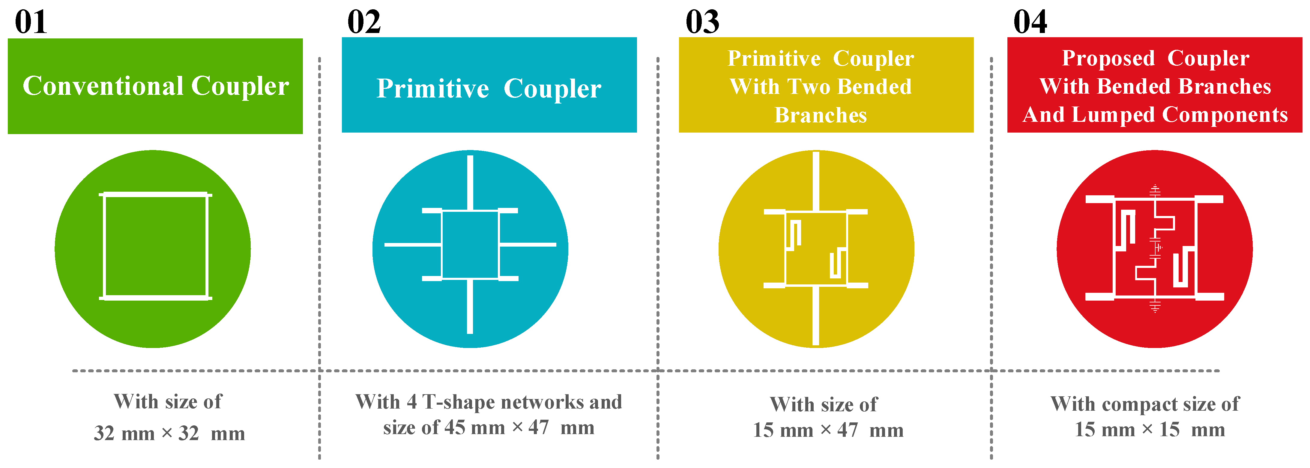
In all of the explained research, the coupler parameters are not simultaneously improved, while some features are enhanced. In the proposed designed, a simple QHC with four T-shaped networks is proposed, and the presented design is analyzed. Then, two horizontal branches are bended to reduce the circuit size, where the achieved coupler provides a 30% of size reduction in this step. Finally, the long vertical branches are replaced with the proposed composite lines, including two capacitors and a microstrip line with π-shaped structure, and the proposed QHC shows a 78% size reduction, compared with the typical coupler.

2. The Conventional 1600 MHz Quadrature Hybrid Coupler

The diagram in Figure 1a displays the configuration of the typical 1600 MHz quadrature hybrid coupler. It includes four lengthy λ/4 branches that correspond to two vertical branches with 50 Ω and two horizontal lines with 35 Ω. Using the Rogers_RO4003 substrate (with εr = 3.38 and thickness of 20 mil), the typical coupler dimensions are 32 mm × 32 mm, equivalent to 0.25 λ × 25 λ. However, the device’s large size is a disadvantage of this conventional design.
Figure 1b illustrates the frequency response of the typical 1600 MHz quadrature hybrid coupler. The S21 and S31 parameters exhibit −3.05 dB amplitudes, indicating a 0.05 dB insertion loss at the operating frequency. The S11 and S41 have amplitudes below −35 dB, demonstrating the excellent performance of the conventional coupler at the operating frequency. However, the conventional QHC is not suitable for higher frequencies as it lacks sufficient suppression of unwanted signals, which is a significant drawback of this design.

3. Design Process of the Primitive 1600 MHz Quadrature Hybrid Coupler with T-Shaped Branches

The design flowchart of the designed coupler is demonstrated in four steps in Figure 2. In the design process, in the first step, the conventional coupler is designed, then in the second step, the primitive coupler is provided, with four T-shaped structures. All dimensions of the primitive coupler are obtained analytically. However, this structure has a large size of 45 mm × 47 mm. In the third step, two long horizontal branches are bended, but this structure still has a large size of 15 mm × 47 mm. Finally, composite π-shaped networks with lumped elements are applied instead of two long vertical branches. All values of applied lumped elements are obtained analytically. The proposed coupler has an ultra-small size of 15 mm × 15 mm, which demonstrates a 78% size reduction compared with the typical structure. The proposed coupler has a straight forward design process and has an ultra-compact size.
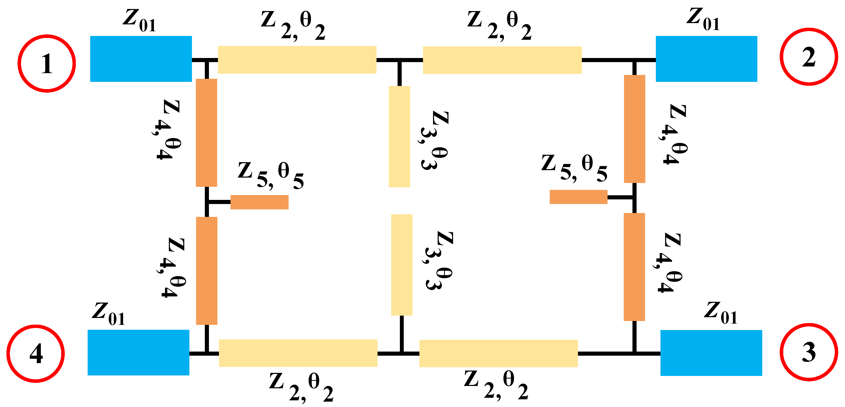
The typical microstrip coupler occupies a large area, and also, it cannot suppress harmonics at higher frequencies, which is undesirable. To overcome these disadvantages, the designed structure of the primitive coupler is demonstrated in Figure 3, in which four T-shaped branches are used in the structure of the typical QHC.
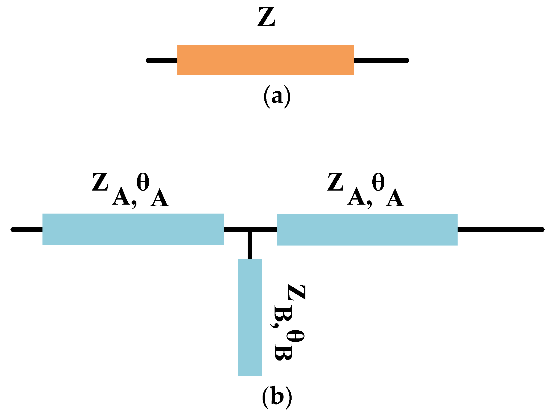
In order to find the dimensions of the utilized branches in the primitive coupler, four applied T-shaped branches are considered to be equivalent to the four typical branches. Therefore, as seen in Figure 4, the applied typical stub in the conventional QHC and applied T-shaped stubs in the primitive QHC should have same response.
The ABCD matrix for the microstrip line with impedance of ZA and electrical length of θA can be obtained from Equation (1) as follows:
[ ABCD ] = cos ( θ A ) j Z A sin ( θ A ) j sin ( θ A ) Z A cos ( θ A )
The conventional QHC has four branches with λ/4 electrical length. Two horizontal branches have Z0/√2 Ω impedance and two vertical branches have Z0 Ω impedance. The ABCD matrices for the conventional lines with Z0 and Z0/√2 impedances are listed as Equations (2) and (3) as follows:
[ ABCD ] = 0 j Z 0 2 j 2 Z 0 0
[ ABCD ] = 0 j Z 0 j Z 0 0
The ABCD matrix for the T-shaped branches can be calculated by multiplying the ABCD matrices of each stub, as shown in Figure 5.
The ABCD matrix for the shunt load on the T-shaped stub indicated with ZB and θB can be calculated as written in Equation (4).
[ A B C D ] Y = 1 0 Y S 1
where the Ys can be calculated as follows:
Y s = j Y B   cot ( θ B )
Therefore, the ABCD matrix for the T-shaped structure can be obtained as written in Equation (6).
[ A B C D ] T s h a p e d = cos ( θ A ) j Z A sin ( θ A ) j sin ( θ A ) Z A cos ( θ A ) × 1 0 j Y B c o t ( θ B ) 1 × cos ( θ A ) j Z A sin ( θ A ) j sin ( θ A ) Z A cos ( θ A )
After some simplification and equating the obtained ABCD matrix of the T-shaped stub with the conventional λ/4 line, the following equations are obtained:
ZA = Z0 cotθA
Z B = 1 2 Z A   t a n θ B   s i n 2 θ A c o s 2 θ A
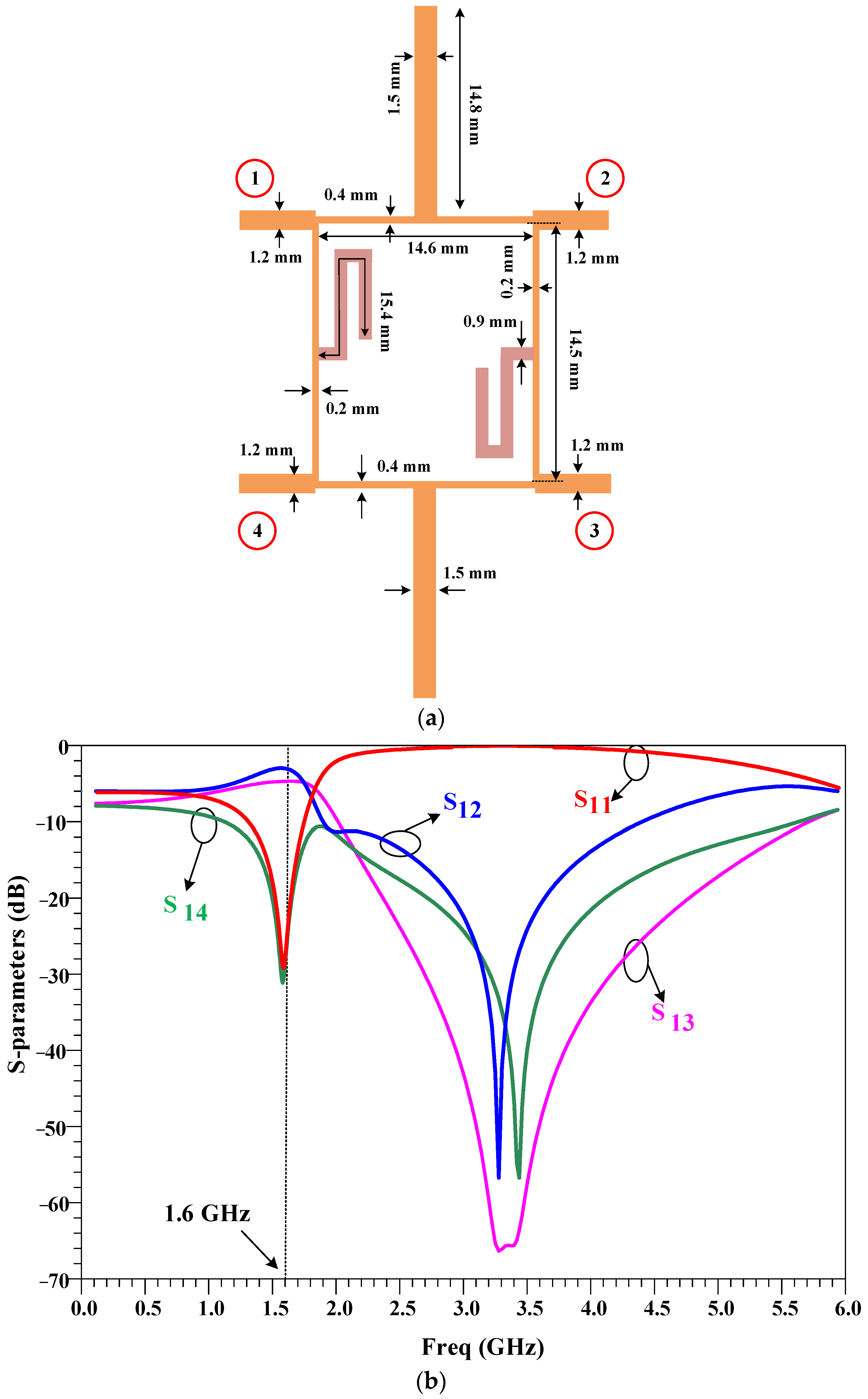
Equation (7) is written for the vertical branches, while Z0 should be substituted with Z0/ 2 for horizontal branches in this equation, because of the conventional coupler structure. The obtained values for the T-shaped branches are listed in Table 1.
The layout of the primitive coupler is depicted in Figure 6a, and its frequency response is depicted in Figure 6b. This coupler has a large size and occupies an area of 47 mm × 45.1 mm, which is larger than the conventional coupler. It should be noted that L3 = 15.25 mm, L5 = 15.6 mm, W3 = 1.5 mm and W5 = 0.9 mm are obtained from analyses, as listed in Table 1. These dimensions are tuned using the EM simulation, which are equal to L3 = 14.8 mm, L5 = 15.2 mm, W3 = 1.5 mm and W5 = 0.9 mm, which shows that the EM simulation and analysis results have validated each other.

4. Design Process of the Primitive 1600 MHz Quadrature Hybrid Coupler with T-Shaped Branches and Bended Stubs

Open stubs are used in couplers to improve their performance as the common method, so that they can provide a wider bandwidth. Additionally, open stubs can be used to improve the isolation between the coupled and isolated ports of the coupler. However, there are some drawbacks to using open stubs in couplers. One major disadvantage is that they can increase the size of the coupler, which may not be desirable for some applications. To reduce the size of microstrip couplers while maintaining their performance, meandered lines or bent lines methods can be used.
As the results show, the primitive 1600 MHz quadrature hybrid coupler with T-shaped branches occupies a large area. Therefore, to reduce the circuit size, two horizontal stubs are bended as depicted in Figure 7a, and its frequency response is depicted in Figure 7b. This coupler has a relatively large size and occupies an area of 47 mm × 15 mm, which provides a 30% size reduction, compared with the conventional coupler.

5. Design Process of the Proposed 1600 MHz Quadrature Hybrid Coupler

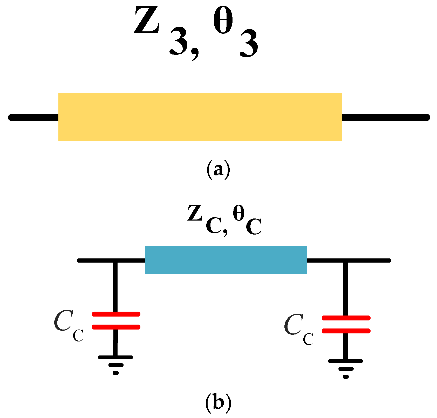
As seen in the previous section, two vertical open stubs in the primitive coupler have long lengths, which resulted in the large size of the primitive coupler. Therefore, to reduce the size of these stubs, lumped capacitors are used with a microstrip line as a composite line, as shown in Figure 8.
Applied lumped capacitors in the microstrip coupler have a number of advantages. They allow for the tuning of the coupler’s performance to meet specific requirements. This is because the capacitance of the lumped capacitor can be adjusted to alter the coupling coefficient and bandwidth of the coupler.
However, there are also some drawbacks to using applied lumped capacitors in microstrip couplers. One major disadvantage is that they can introduce unwanted parasitic effects, which can degrade the performance of the coupler. Additionally, the use of lumped capacitors can limit the frequency range over which the coupler can operate effectively.
To obtain the element values of the composite line in the designed QHC, the ABCD matrix analyses are used. The ABCD matrices of capacitors and the ZC transmission line are written in Equations (9) and (10) as follows:
M C = ( 1 0 C ω i 1 )
M Z C = ( cos ( θ C ) Z C sin ( θ C ) i sin ( θ C ) i Z C cos ( θ C ) )
To have the same response, both simple stub and π-shaped networks should have equal ABCD matrices. So, the final equations can be written by creating the equation of MC × MZC × MC = MZ3 as shown in Equation (11):
( cos ( θ C ) C Z C ω sin ( θ C ) Z C ω sin ( θ C ) i sin ( θ C ) i Z C + C ω ( cos θ C C Z C ω sin ( θ C ) ) i + C ω cos ( θ C ) i cos ( θ C ) C Zc ω sin ( θ C ) ) = ( cos ( θ 3 ) Z 3 sin ( θ 3 ) i sin ( θ 3 ) i Z 3 cos ( θ 3 ) )
One solution for Equation (11) is calculated, and the obtained values are written in Table 2.
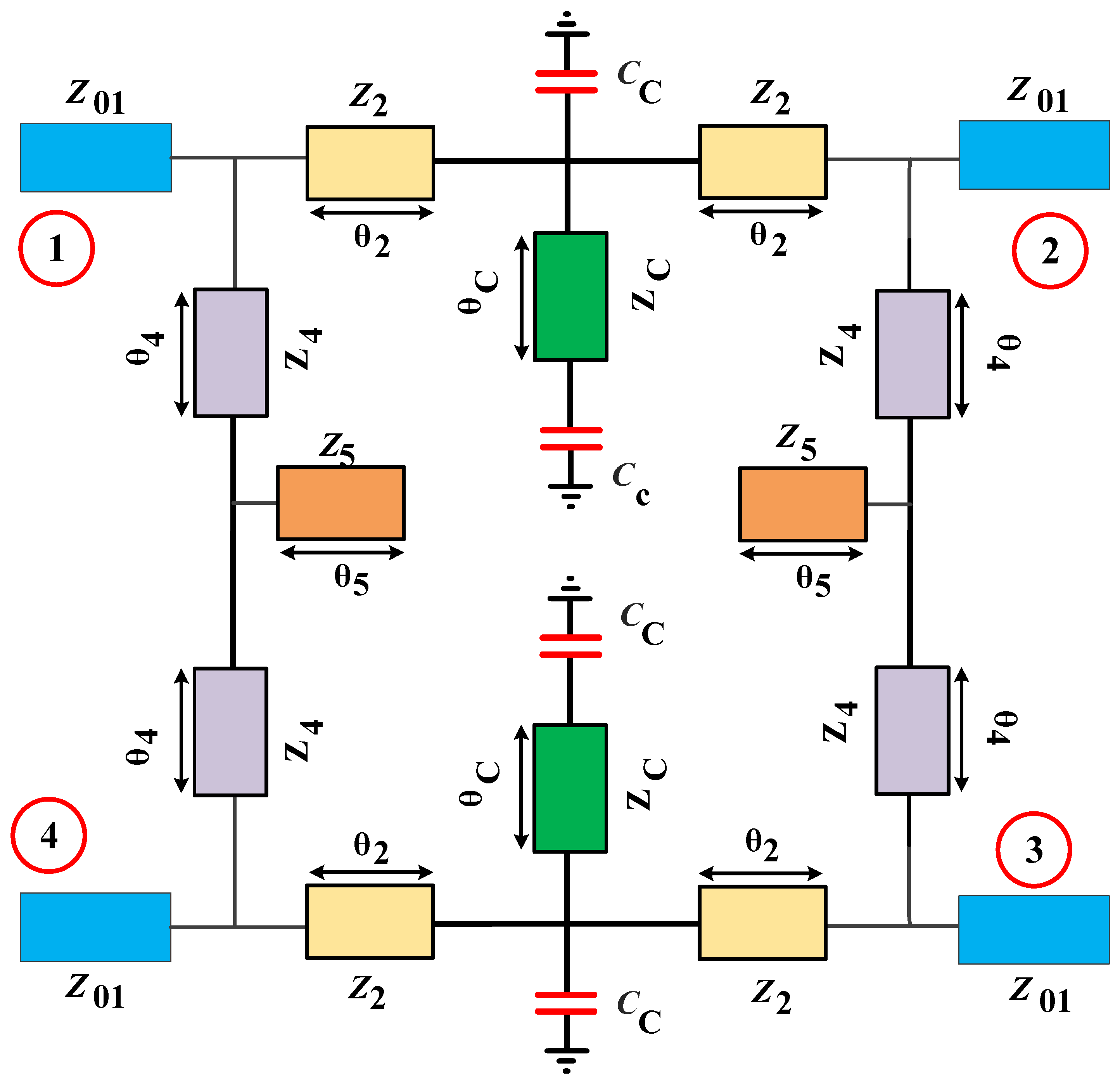
The schematic diagram of the proposed 1600 MHz quadrature hybrid coupler is depicted in Figure 9, and in this symmetric structure, microstrip stubs and lumped capacitors are used together.
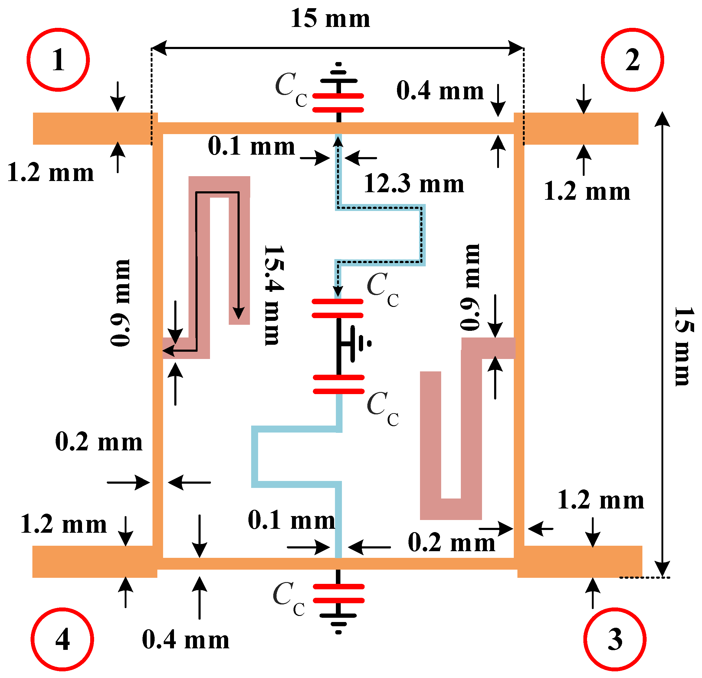
The typical QHC is often bulky and allows unwanted signals to pass through without suppression at higher frequencies. To address these issues, a new QHC design featuring four lumped capacitors and two open-ended stubs at 1600 MHz has been proposed. The resulting layout is depicted in Figure 10, which provides an ultra-compact size of only 15 mm × 15 mm, equaling to 0.12 λ × 0.12 λ, representing a 78% reduction in size compared to the conventional 1600 MHz coupler. In the proposed structure, two symmetric meandered stubs and two symmetric π-shaped composite networks including capacitors and microstrip lines are used together.
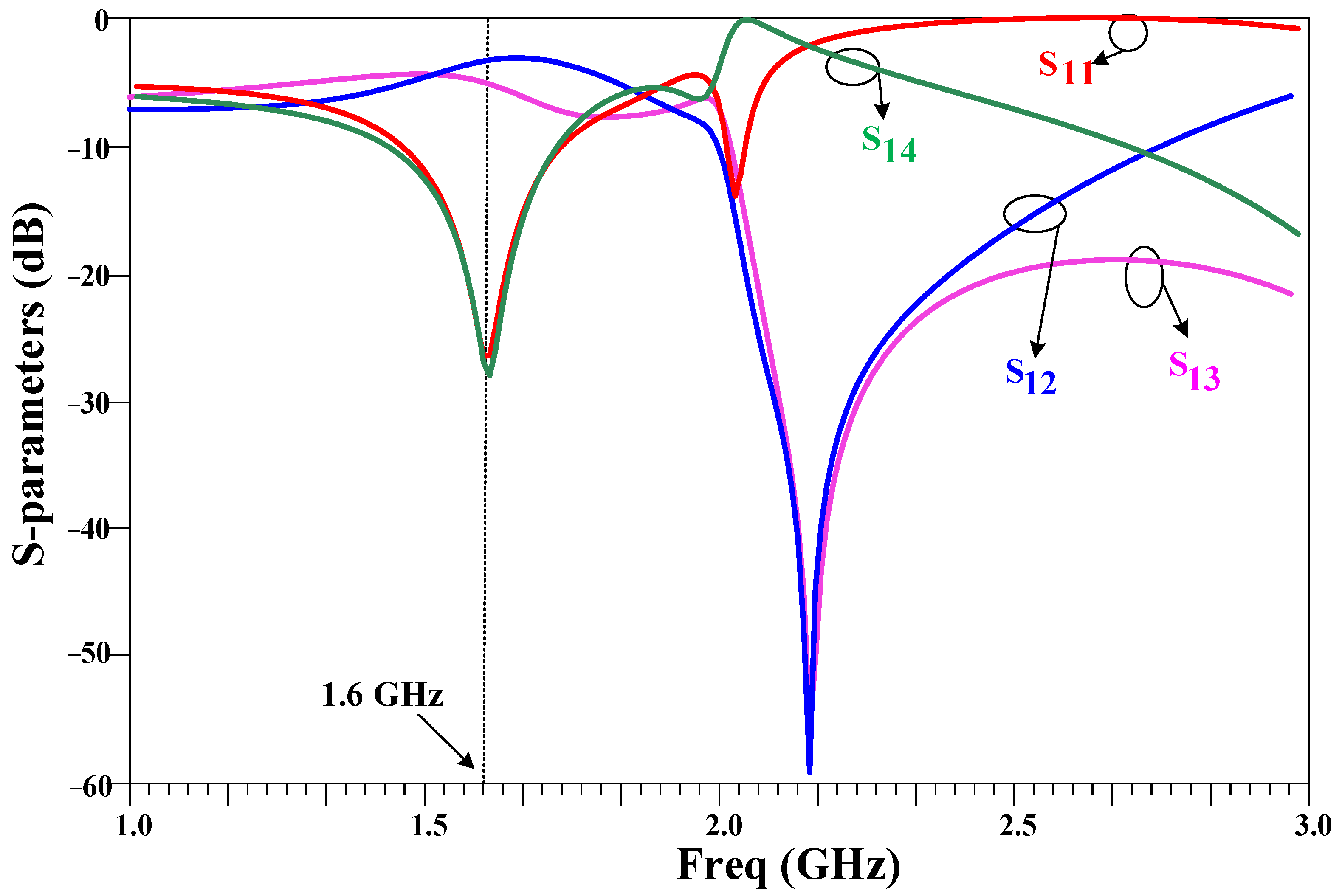
Figure 11 displays the S-parameters of the proposed QHC with lumped components at 1600 MHz. The designed QHC exhibits an excellent performance at this frequency and offers a stop band from 2 GHz to 2.4 GHz with attenuation levels exceeding 20 dB. The coupler operates effectively within a 400 MHz bandwidth at 1600 MHz, indicating a fractional bandwidth of 25%.
As seen in Figure 11, there is a small unbalance between the output ports at the operating frequency, which is due to an adjustment in the values of the lumped components and meandered open stubs dimension, which are tuned for the size reduction in the proposed coupler.
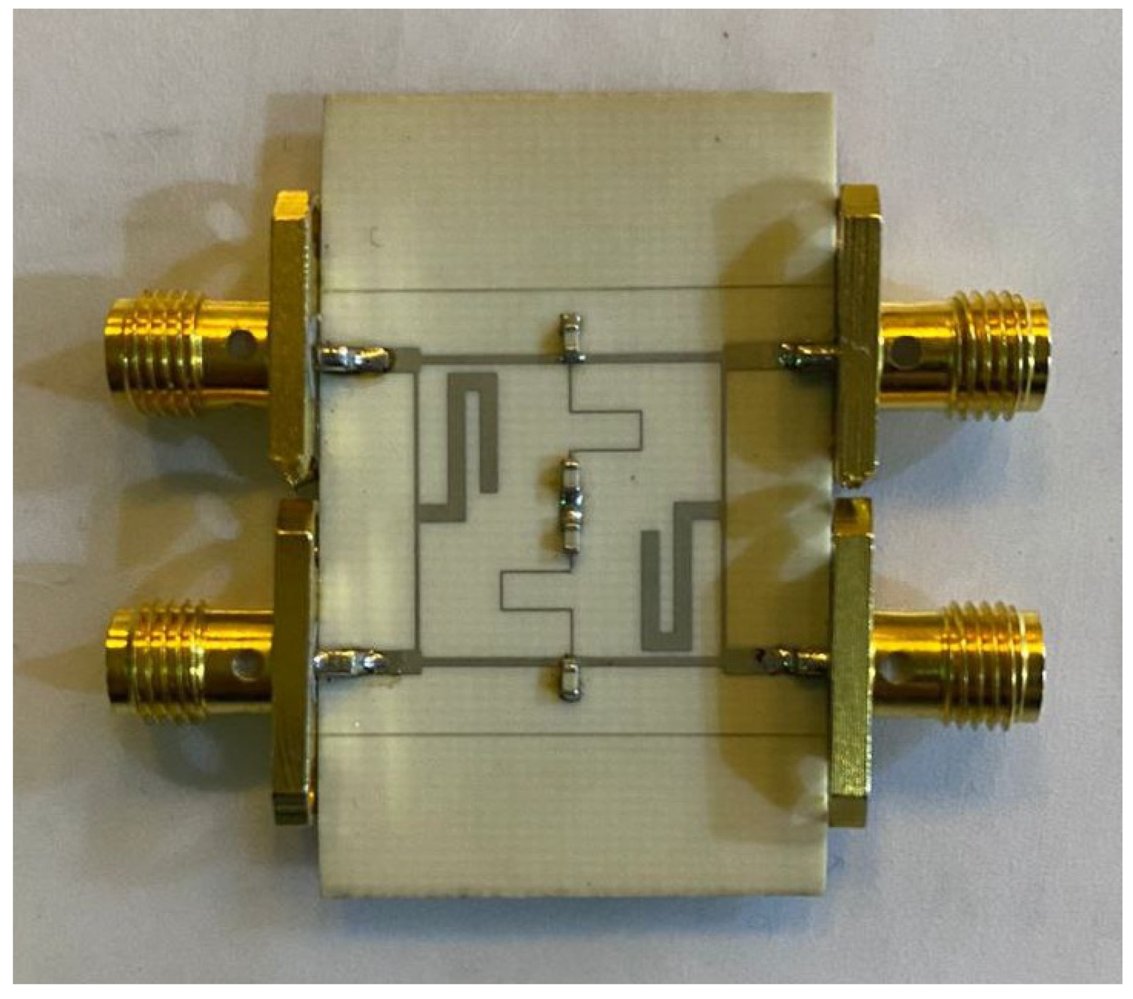
The fabricated photo of the proposed 1600 MHz coupler is illustrated in Figure 12, which was fabricated on the Rogers_RO4003 substrate with εr = 3.38 and 20 mil thickness.
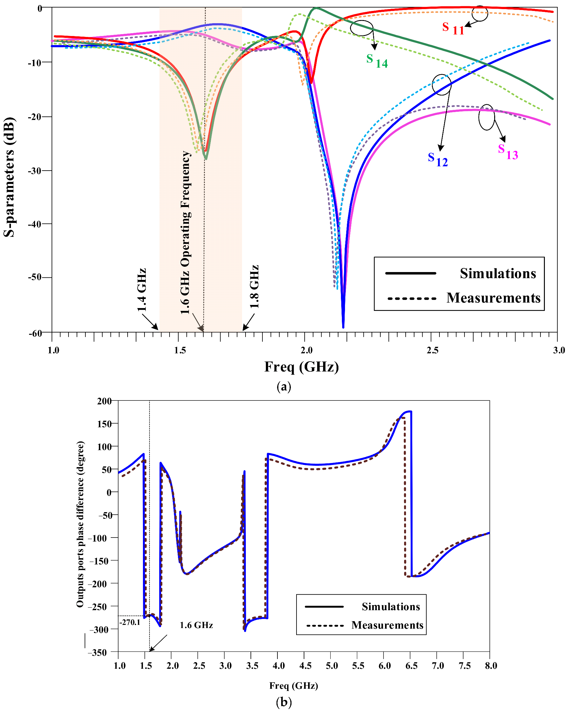
Figure 13 shows the S-parameters of the proposed 1600 MHz QHC, both measured and simulated. The proposed QHC performs flawlessly at 1600 MHz and has a wide operating bandwidth of approximately 400 MHz, equivalent to a 25% fractional bandwidth (FBW). Table 3 compares the proposed 1600 MHz QHC with other similar works. The proposed coupler offers the best size reduction compared to other reported works and delivers good performance in comparison to related works.

6. Conclusions

In this study, a compact quadrature hybrid coupler (QHC) utilizing lumped components and meandered stubs is proposed. The design incorporates four T-shaped branches and four lumped capacitors instead of conventional branches. The proposed QHC performs well at 1600 MHz with a 400 MHz bandwidth, equivalent to a 25% fractional bandwidth (FBW). The size of the proposed QHC is ultra-compact, occupying only 22% of the size of a typical coupler. The proposed coupler occupies only an area of 15 mm × 15 mm (0.12 λ × 0.12 λ), compared to the conventional 1600 MHz coupler size of 32 mm × 32 mm (0.25 λ × 25 λ). Additionally, the proposed QHC exhibits a suppression band from 2 GHz to 2.4 GHz with a more than 20 dB attenuation level. Experimental results confirm the validity of the simulated results. Overall, the proposed QHC outperforms other similar works in terms of the size reduction and provides good performance compared to related works.

Author Contributions

Conceptualization, S.R. (Saeed Roshani), and S.R. (Sobhan Roshani); methodology, S.I.Y.; software, S.M.A. and S.R. (Saeed Roshani); validation, M.A., M.A.C., Y.Y.G. and F.H.; formal analysis, M.A., M.A.C. and F.H.; investigation, S.R. (Saeed Roshani), and S.R. (Sobhan Roshani); resources, Y.Y.G. and S.M.A.; writing—original draft preparation, S.R. (Saeed Roshani), S.R. (Sobhan Roshani), S.I.Y. and S.M.A.; writing—review and editing, M.A., M.A.C., F.H. and Y.Y.G.; visualization, S.R. (Saeed Roshani), and S.R. (Sobhan Roshani); supervision, S.R. (Saeed Roshani); project administration, S.I.Y. and S.R. (Sobhan Roshani). All authors have read and agreed to the published version of the manuscript.

Funding

This research received no external funding.

Data Availability Statement

All the material conducted in the study is mentioned in the article.

Conflicts of Interest

The authors declare no conflict of interest.

References

  1. Roshani, S.; Yahya, S.I.; Roshani, S.; Farahmand, A.H.; Hemmati, S. Design of a modified compact coupler with unwanted harmonics suppression for L-band applications. Electronics 2022, 11, 1747. [Google Scholar] [CrossRef]
  2. Roshani, S.; Yahya, S.I.; Roshani, S.; Rostami, M. Design and fabrication of a compact branch-line coupler using resonators with wide harmonics suppression band. Electronics 2022, 11, 793. [Google Scholar] [CrossRef]
  3. Alizadeh, S.; Roshani, S.; Roshani, S. A modified branch line coupler with compact size and ultra wide harmonics suppression band. Electromagnetics 2022, 42, 377–387. [Google Scholar] [CrossRef]
  4. Arigong, B.; Zhou, M.; Ren, H.; Chen, C.; Zhang, H. A Compact Lumped-Component Coupler with Tunable Coupling Ratios and Reconfigurable Responses. In Proceedings of the 2018 IEEE/MTT-S International Microwave Symposium-IMS, Philadelphia, PA, USA, 10–15 June 2018; IEEE: Piscataway, NJ, USA, 2018. [Google Scholar]
  5. Beigizadeh, M.; Dehghani, R.; Nabavi, A. Analysis and design of a lumped-element hybrid coupler using limited quality factor of components. AEU-Int. J. Electron. Commun. 2017, 82, 312–320. [Google Scholar] [CrossRef]
  6. Chen, Z.; Wu, Y.; Yang, Y.; Wang, W. A novel unequal lumped-element coupler with arbitrary phase differences and arbitrary impedance matching. IEEE Trans. Circuits Syst. II Express Briefs 2021, 69, 369–373. [Google Scholar] [CrossRef]
  7. Vogel, R.W. Analysis and design of lumped-and lumped-distributed-element directional couplers for MIC and MMIC applications. IEEE Trans. Microw. Theory Tech. 1992, 40, 253–262. [Google Scholar] [CrossRef]
  8. Roshani, S.; Yahya, S.I.; Alameri, B.M.; Mezaal, Y.S.; Liu, L.W.; Roshani, S. Filtering power divider design using resonant LC branches for 5G low-band applications. Sustainability 2022, 14, 12291. [Google Scholar] [CrossRef]
  9. Barik, R.K.; Koziel, S.; Bernhardsson, E. Design of Frequency-Reconfigurable Branch-Line Crossover Using Rectangular Dielectric Channels. IEEE Access 2023, 11, 38072–38081. [Google Scholar] [CrossRef]
  10. Wang, D.; Song, J.; Li, X.; Qin, Q.; Sun, L. Design of wideband and compact lumped-element couplers for 5G communication. In Proceedings of the 2020 IEEE 6th International Conference on Computer and Communications (ICCC), Chengdu, China, 11–14 December 2020; IEEE: Piscataway, NJ, USA, 2020. [Google Scholar]
  11. Kumar, K.P.; Karthikeyan, S. Wideband three section branch line coupler using triple open complementary split ring resonator and open stubs. AEU-Int. J. Electron. Commun. 2015, 69, 1412–1416. [Google Scholar] [CrossRef]
  12. Chang, W.-L.; Huang, T.-Y.; Shen, T.-M.; Chen, B.-C.; Wu, R.-B. Design of compact branch-line coupler with coupled resonators. In Proceedings of the 2007 Asia-Pacific Microwave Conference, Bangkok, Thailand, 11–14 December 2007; IEEE: Piscataway, NJ, USA, 2007. [Google Scholar]
  13. Lu, K.; Wang, G.-M.; Zhang, C.-X.; Wang, Y.-W. Design of miniaturized branch-line coupler based on novel spiral-based resonators. J. Electromagn. Waves Appl. 2011, 25, 2244–2253. [Google Scholar] [CrossRef]
  14. Lin, T.-W.; Lin, C.-H.; Huang, K.-C.; Kuo, J.-T. Compact branch-line coupler filter with transmission zeros. In Proceedings of the 2015 Asia-Pacific Microwave Conference (APMC), Nanjing, China, 6–9 December 2015; IEEE: Piscataway, NJ, USA, 2015. [Google Scholar]
  15. Ghaffarian, M.S.; Moradi, G.; Khajehpour, S.; Honari, M.M.; Mirzavand, R. Dual-band/dual-mode rat-race/branch-line coupler using split ring resonators. Electronics 2021, 10, 1812. [Google Scholar] [CrossRef]
  16. Niu, J.X.; Zhou, X.L. A novel dual-band branch line coupler based on strip-shaped complementary split ring resonators. Microw. Opt. Technol. Lett. 2007, 49, 2859–2862. [Google Scholar] [CrossRef]
  17. Al-Khateeb, L. Miniaturized hybrid branch line couplers based on a square-split resonator loading technique. Prog. Electromagn. Res. Lett. 2013, 40, 153–162. [Google Scholar] [CrossRef]
  18. Safia, O.A.; Talbi, L.; Hettak, K. A new type of transmission line-based metamaterial resonator and its implementation in original applications. IEEE Trans. Magn. 2013, 49, 968–973. [Google Scholar] [CrossRef]
  19. Yahya, S.I.; Rezaei, A.; Khaleel, Y.A. Design and Analysis of a Wide Stopband Microstrip Dual-band Bandpass Filter. ARO-Sci. J. Koya Univ. 2021, 9, 83–90. [Google Scholar] [CrossRef]
  20. Yahya, S.I.; Rezaei, A. Design and Fabrication of a Novel Ultra Compact Microstrip Diplexer Using Interdigital and Spiral Cells. ARO-Sci. J. Koya Univ. 2021, 9, 103–108. [Google Scholar] [CrossRef]
  21. Nouri, L.; Yahya, S.I.; Rezaei, A.; Hazzazi, F.A.; Nhu, B.N. A Compact Negative Group Delay Microstrip Diplexer with Low Losses for 5G Applications. Aro-Sci. J. Koya Univ. 2023, 11, 17–24. [Google Scholar] [CrossRef]
  22. Azadi, R.; Roshani, S.; Nosratpour, A.; Lalbakhsh, A.; Mozaffari, M.H. Half-elliptical resonator lowpass filter with a wide stopband for low band 5G communication systems. Electronics 2021, 10, 2916. [Google Scholar] [CrossRef]
  23. Golestanifar, A.; Karimi, G.; Lalbakhsh, A. Varactor-tuned wideband band-pass filter for 5G NR frequency bands n77, n79 and 5G Wi-Fi. Sci. Rep. 2022, 12, 16330. [Google Scholar] [CrossRef] [PubMed]
  24. Jamshidi, M.; Lalbakhsh, A.; Lotfi, S.; Siahkamari, H.; Mohamadzade, B.; Jalilian, J. A neuro-based approach to designing a Wilkinson power divider. Int. J. RF Microw. Comput. Aided Eng. 2020, 30, e22091. [Google Scholar] [CrossRef]
  25. Lalbakhsh, A.; Afzal, M.U.; Esselle, K.P.; Smith, S.L. All-metal wideband frequency-selective surface bandpass filter for TE and TM polarizations. IEEE Trans. Antennas Propag. 2022, 70, 2790–2800. [Google Scholar] [CrossRef]
  26. Lalbakhsh, A.; Alizadeh, S.M.; Ghaderi, A.; Golestanifar, A.; Mohamadzade, B.; Jamshidi, M.; Mandal, K.; Mohyuddin, W. A design of a dual-band bandpass filter based on modal analysis for modern communication systems. Electronics 2020, 9, 1770. [Google Scholar] [CrossRef]
  27. Lalbakhsh, A.; Ghaderi, A.; Mohyuddin, W.; Simorangkir, R.B.; Bayat-Makou, N.; Ahmad, M.S.; Lee, G.H.; Kim, K.W. A compact C-band bandpass filter with an adjustable dual-band suitable for satellite communication systems. Electronics 2020, 9, 1088. [Google Scholar] [CrossRef]
  28. Moloudian, G.; Soltani, S.; Bahrami, S.; Buckley, J.L.; O’Flynn, B.; Lalbakhsh, A. Design and fabrication of a Wilkinson power divider with harmonic suppression for LTE and GSM applications. Sci. Rep. 2023, 13, 4246. [Google Scholar] [CrossRef]
  29. Pradhan, N.C.; Koziel, S.; Barik, R.K.; Pietrenko-Dabrowska, A.; Karthikeyan, S.S. Miniaturized Dual-Band SIW-Based Bandpass Filters Using Open-Loop Ring Resonators. Electronics 2023, 12, 3974. [Google Scholar] [CrossRef]
  30. Koziel, S.; Haq, T. Uncertainty quantification of additive manufacturing post-fabrication tuning of resonator-based microwave sensors. Measurement 2023, 216, 112952. [Google Scholar] [CrossRef]
  31. Haq, T.; Koziel, S. Rapid design optimization and calibration of microwave sensors based on equivalent complementary resonators for high sensitivity and low fabrication tolerance. Sensors 2023, 23, 1044. [Google Scholar] [CrossRef]
  32. Tang, C.-W.; Chen, M.-G.; Lin, Y.-S.; Wu, J.-W. Broadband microstrip branch-line coupler with defected ground structure. Electron. Lett. 2006, 42, 1458–1460. [Google Scholar] [CrossRef]
  33. Kim, J.-S.; Kong, K.-B. Compact branch-line coupler for harmonic suppression. Prog. Electromagn. Res. C 2010, 16, 233–239. [Google Scholar] [CrossRef]
  34. Lim, J.-S.; Kim, C.-S.; Park, J.-S.; Ahn, D.; Nam, S. Design of 10 dB 90 branch line coupler using microstrip line with defected ground structure. Electron. Lett. 2000, 36, 1784–1785. [Google Scholar] [CrossRef]
  35. Kim, C.-S.; Lim, J.-S.; Park, J.-S.; Ahn, D.; Nam, S. A 10dB branch line coupler using defected ground structure. In Proceedings of the 2000 30th European Microwave Conference, Paris, France, 2–5 October 2000; IEEE: Piscataway, NJ, USA, 2000. [Google Scholar]
  36. Parandin, F.; Heidari, F.; Rahimi, Z.; Olyaee, S. Two-Dimensional photonic crystal Biosensors: A review. Opt. Laser Technol. 2021, 144, 107397. [Google Scholar] [CrossRef]
  37. Parandin, F.; Sheykhian, A. Design and simulation of a 2 × 1 All-Optical multiplexer based on photonic crystals. Opt. Laser Technol. 2022, 151, 108021. [Google Scholar] [CrossRef]
  38. Parandin, F. Ultra-compact terahertz all-optical logic comparator on GaAs photonic crystal platform. Opt. Laser Technol. 2021, 144, 107399. [Google Scholar] [CrossRef]
  39. Parandin, F.; Kamarian, R.; Jomour, M. A novel design of all optical half-subtractor using a square lattice photonic crystals. Opt. Quantum Electron. 2021, 53, 114. [Google Scholar] [CrossRef]
  40. Wei, F.; Chen, L.; Guo, Y.; Li, W.; Shi, X. Compact UWB directional coupler with one notch-band. J. Electromagn. Waves Appl. 2013, 27, 599–604. [Google Scholar] [CrossRef]
  41. Roshani, S.; Koziel, S.; Yahya, S.I.; Chaudhary, M.A.; Ghadi, Y.Y.; Roshani, S.; Golunski, L. Mutual Coupling Reduction in Antenna Arrays Using Artificial Intelligence Approach and Inverse Neural Network Surrogates. Sensors 2023, 23, 7089. [Google Scholar] [CrossRef]
  42. Calik, N.; Güneş, F.; Koziel, S.; Pietrenko-Dabrowska, A.; Belen, M.A.; Mahouti, P. Deep-learning-based precise characterization of microwave transistors using fully-automated regression surrogates. Sci. Rep. 2023, 13, 1445. [Google Scholar] [CrossRef]
  43. Alibakhshikenari, M.; Ali, E.M.; Soruri, M.; Dalarsson, M.; Naser-Moghadasi, M.; Virdee, B.S.; Stefanovic, C.; Pietrenko-Dabrowska, A.; Koziel, S.; Szczepanski, S. A comprehensive survey on antennas on-chip based on metamaterial, metasurface, and substrate integrated waveguide principles for millimeter-waves and terahertz integrated circuits and systems. IEEE Access 2022, 10, 3668–3692. [Google Scholar] [CrossRef]
  44. Alibakhshikenari, M.; Virdee, B.S.; Benetatos, H.; Ali, E.M.; Soruri, M.; Dalarsson, M.; Naser-Moghadasi, M.; See, C.H.; Pietrenko-Dabrowska, A.; Koziel, S. An innovative antenna array with high inter element isolation for sub-6 GHz 5G MIMO communication systems. Sci. Rep. 2022, 12, 7907. [Google Scholar] [CrossRef]
  45. Roshani, S.; Shahveisi, H. Mutual coupling reduction in microstrip patch antenna arrays using simple microstrip resonator. Wirel. Pers. Commun. 2022, 126, 1665–1677. [Google Scholar] [CrossRef]
  46. Khan, A.; Bashir, S.; Ghafoor, S.; Rmili, H.; Mirza, J.; Ahmad, A. Isolation Enhancement in a Compact Four-Element MIMO Antenna for Ultra-Wideband Applications. Cmc-Comput. Mater. Contin. 2023, 75, 911–925. [Google Scholar]
  47. Khan, A.; Bashir, S.; Ghafoor, S.; Qureshi, K.K. Mutual coupling reduction using ground stub and EBG in a compact wideband MIMO-antenna. IEEE Access 2021, 9, 40972–40979. [Google Scholar] [CrossRef]
  48. Abouhssous, K.; Zugari, A.; Zakriti, A. A compact microstrip coupler using T-shape and open stubs for fifth generation applications. In E3S Web of Conferences; EDP Sciences: Ulys, France, 2022. [Google Scholar]
  49. Chang, W.I.; Chung, M.J.; Park, C.S. Compact High-Directivity Contra-Directional Coupler. Electronics 2022, 11, 4115. [Google Scholar] [CrossRef]
  50. Barik, R.K.; Koziel, S.; Szczepanski, S. Wideband highly-selective bandpass filtering branch-line coupler. IEEE Access 2022, 10, 20832–20838. [Google Scholar] [CrossRef]
  51. Parsaei, K.; Keshavarz, R.; Boroujeni, R.M.; Shariati, N. Compact Pixelated Microstrip Forward Broadside Coupler Using Binary Particle Swarm Optimization. IEEE Trans. Circuits Syst. I: Regul. Pap. 2023, 1–10. [Google Scholar] [CrossRef]
  52. Tayebi, A.; Zarifi, D. On the miniaturization of microstrip ring-hybrid couplers using Gielis supershapes. IETE J. Res. 2023, 69, 1160–1165. [Google Scholar] [CrossRef]
  53. Li, C.; Ma, Z.-H.; Chen, J.-X.; Wang, M.-N.; Huang, J.-M. Design of a Compact Ultra-Wideband Microstrip Bandpass Filter. Electronics 2023, 12, 1728. [Google Scholar] [CrossRef]
  54. El-Rahman, A.; Sherine, I.; Ibrahim, K.M.; Attiya, A.M. A Dual-Band Rat Race Coupler for WLAN Applications. Int. J. Microw. Opt. Technol. 2023, 18, 473–480. [Google Scholar]
  55. Krishna, I.S.; Barik, R.K.; Karthikeyan, S.; Kokil, P. A miniaturized harmonic suppressed 3 dB branch line coupler using H-shaped microstrip line. Microw. Opt. Technol. Lett. 2017, 59, 913–918. [Google Scholar] [CrossRef]
  56. Chen, C.-F.; Chang, S.-F.; Tseng, B.-H. Compact microstrip dual-band quadrature coupler based on coupled-resonator technique. IEEE Microw. Wirel. Compon. Lett. 2016, 26, 487–489. [Google Scholar] [CrossRef]
  57. Reshma, S.; Mandal, M.K. Miniaturization of a 90° hybrid coupler with improved bandwidth performance. IEEE Microw. Wirel. Compon. Lett. 2016, 26, 891–893. [Google Scholar] [CrossRef]
  58. Nie, W.; Luo, S.; Guo, Y.-X.; Fan, Y. Miniaturized rat-race coupler with harmonic suppression. IEEE Microw. Wirel. Compon. Lett. 2014, 24, 754–756. [Google Scholar] [CrossRef]
  59. Wang, W.-H.; Shen, T.-M.; Huang, T.-Y.; Wu, R.-B. Miniaturized rat-race coupler with bandpass response and good stopband rejection. In Proceedings of the 2009 IEEE MTT-S International Microwave Symposium Digest, Boston, MA, USA, 7–12 June 2009; IEEE: Piscataway, NJ, USA, 2009. [Google Scholar]
Figure 1. The (a) configuration and (b) S-parameters of the typical 1600 MHz quadrature hybrid coupler with four long λ/4 branches.
Symmetry 15 02149 g001
Figure 2. Design flowchart of the proposed coupler. All dimensions are calculated analytically.
Symmetry 15 02149 g002
Figure 3. The structure of the primitive coupler with T-shaped branches.
Symmetry 15 02149 g003
Figure 4. The (a) applied typical stub in the conventional QHC and (b) its equivalent T-shaped stub in the primitive QHC.
Symmetry 15 02149 g004
Figure 5. The ABCD matrix calculation for applied T-shaped stub in the primitive QHC.
Symmetry 15 02149 g005
Figure 6. The (a) layout and the (b) frequency response of the primitive QHC.
Symmetry 15 02149 g006
Figure 7. The (a) layout and the (b) frequency response of the primitive QHC with bended stubs.
Symmetry 15 02149 g007
Figure 8. The (a) applied long vertical stub in the primitive QHC and (b) applied π-shaped network in the proposed QHC to reduce size.
Symmetry 15 02149 g008
Figure 9. The schematic diagram of the proposed 1600 MHz quadrature hybrid coupler using four lumped capacitors.
Symmetry 15 02149 g009
Figure 10. The layout of the proposed 1600 MHz quadrature hybrid coupler with lumped components.
Symmetry 15 02149 g010
Figure 11. The S-parameters of the proposed 1600 MHz quadrature hybrid coupler with lumped components.
Symmetry 15 02149 g011
Figure 12. The fabricated picture of the proposed 1600 MHz QHC on the Rogers_RO4003 substrate with εr = 3.38 and 20 mil thickness.
Symmetry 15 02149 g012
Figure 13. The simulated and measured curves of the proposed 1600 MHz QHC for the (a) amplitude and (b) phase parameters.
Symmetry 15 02149 g013
Table 1. The obtained values of the T-shaped branches in the primitive coupler.
ParameterZ01Z2Z3Z4Z5θ2θ3θ4θ5
Value50 Ω84 Ω42 Ω120 Ω60 Ω22.5⁰45⁰22.5⁰45⁰
L (mm)57.515.257.515.67.515.57.515.5
W (mm)1.20.41.50.20.9----
Table 2. The obtained values of the π-shaped network.
ParametersZcCcθc
values140 (Ω)0.5 (pF)36⁰
Table 3. Comparison between proposed 1600 MHz QHC and other related works.
Ref.Operation Frequency
(GHz)
Return Loss (dB)Isolation
(dB)
Insertion Loss (dB)Phase
Difference
(Degree)
Size
Reduction
Bandwidth
(MHZ)
FBWApplied Method
[55]0.928280.2690 ± 0.364%18020%H-shaped Lines
[56]1.6/2.121242.490 ± 2.8/90 ± 4.5-150/3009%/14%Coupled Resonators
[57]131260.690 ± 1.267%12412.4%Coupled Lines
[58]2.420200.40 ± 1.470%65027%Open Stubs
[59]217321.40 ± 0.949%1105%Coupled Resonator
This work1.627280.490 ± 0.178%40025%Lumped Elements
and Meandered Lines
Disclaimer/Publisher’s Note: The statements, opinions and data contained in all publications are solely those of the individual author(s) and contributor(s) and not of MDPI and/or the editor(s). MDPI and/or the editor(s) disclaim responsibility for any injury to people or property resulting from any ideas, methods, instructions or products referred to in the content.