Article

The Influence of Increased Electron Energy Spread on the Radiation of the Second Harmonic in Free Electron Lasers

by
Konstantin Zhukovsky
1,2
1
Department of Theoretical Physics, Faculty of Physics, M.V. Lomonosov Moscow State University, Moscow 119991, Russia
2
Wigner Research Centre for Physics, 1121 Budapest, Hungary
Symmetry 2023, 15(12), 2180; https://doi.org/10.3390/sym15122180
Submission received: 18 July 2023 / Revised: 22 November 2023 / Accepted: 6 December 2023 / Published: 9 December 2023
(This article belongs to the Section Physics)

Abstract

:
Free electron lasers (FELs) are becoming more and more popular as sources of radiation for research purposes in many fields of science. They are frequently employed in second harmonic generation (SHG) studies. SHG is an important effect of nonlinear responses of matter to irradiation. It should be separated from the second harmonic of the radiation source, FELs, for correct analysis of the response. Using an analytical model for harmonic powers evolution in a single-pass FEL, we demonstrate the dependence of FEL harmonics on the key parameters of beams and undulators and show that it is possible to reduce the second FEL harmonic content if the energy spread of an electron beam is increased. For LEUTL FEL radiation in the visible range, we analytically demonstrate a reduction in the second harmonic power by an order of magnitude if electron energy spread is increased twice, which still allows efficient bunching at the fundamental wavelength. The method is valid regardless of the photon energy and, therefore, the absorption edge of the target material, and as such, it is valid also in the X-ray band.

1. Introduction

In 21st century studies of properties of materials and their surfaces, biomolecules, crystalline structures, micro- and nano-objects often employs high-power sources of X-ray radiation, such as synchrotrons and free electron lasers (FELs) [1,2,3,4,5,6,7,8,9,10,11,12,13,14,15,16,17,18,19,20,21,22,23,24,25,26,27,28,29,30,31,32,33]. Most radiation sources exploit a single pass of radiation in an FEL amplifier; although, proposals for Klystron-like devices with oscillators exist [34]. These facilities operate in a wide range of frequencies from visible to hard X-rays. Correct response detection from a studied sample is of paramount importance, so scintillators and visualizers are used with novel materials and technologies [35,36,37,38] to capture the signal.
Second harmonic generation (SHG) is an important effect of non-linear optics used for studies in many fields in physics [39], chemistry [40] and other sciences. For example, the second order harmonic generation occurs when radiation interacts with matter, featuring broken inversion symmetry. The SHG response in visible range occurs in studies of chemical states of molecules at surfaces and interfaces [40,41]; light conversion to even harmonics is also an application [42,43]. Short femto- and attosecond pulses of X-ray radiation [44] give the SHG element selectivity through the inner-core excitation resonance. Main X-ray sources, the European X-FEL [3,4,5,6,7], PAL-XFEL [8,9,10,11,12], LCLS [13,14,15,16], Swiss-XFEL [17,18,19,20,21], SACLA [24,25,26,27,28,29,30], operate in both soft and hard X-ray bands; FLASH-II [1,2], ELETTRA [33] and some other FELs with a variable undulator parameter specifically operate in the soft X-ray band. In studies with SHG, the detected signal must be separated from other radiations for clear analysis. The SHG can be separated from the reflected fundamental by grating. However, the second-order harmonic response of the matter must be separated also from the second harmonic of the FEL. The second harmonic in FEL radiation appears due to multiple reasons, mainly due to off-axis effects in undulators (see for example, [45,46,47,48,49,50,51,52,53,54,55]); it is reflected by the examined sample and mixed with the detected signal of the SHG. Such contamination shadows the SHG and makes unclear the detected response; its interpretation and understanding may be erroneous in this case. Thus, in studies of the SHG, it is desirable to suppress the second harmonic of the radiation source. It should be noted that the second harmonic of a planar undulator radiation (UR) is not emitted on the axes in the ideal case when the electron beam is infinitely narrow, it is perfectly aligned, and the undulator is infinitely long and its field is ideally sinusoidal and periodic. Then, even harmonics of the radiation from neighboring undulator periods interfere destructively on the axis, and only odd harmonics are radiated on the axis. However, real beams have a finite section, the undulator field is not ideally sinusoidal and the alignment of the beam is not ideal on the whole length of the undulator section, ~1−4 m; the misalignment and disruption of coherency of electron oscillations accumulate on the total length of undulators: ~10−15 m for an FEL in visible range and ~25−100 m for an FEL in X-ray range. The radiation of the second harmonic in undulators occurs due to several reasons. One of them consists in the betatron oscillations in beams with a finite section (see, for example, [56,57]). Another reason is in the off-axis radiation due to the beam misalignment along the undulators; sometimes the deflection can be comparable with the beam section. In X-ray FELs, the beam section is small, σx,y~10–30 μm; the undulators are long, ~3m; and misalignment of the beam can appear due to the magnetic field of the Earth or due to an imperfect undulator. Field integrals along the undulators are carefully calculated to identify and compensate such fields. However, a major reason for the on-axis even harmonic UR is due to the radiation from the finite section of the beam. The spontaneous UR is received in a finite angle from all electrons in the beam section. The stimulated radiation in an FEL is due to the interaction of the UR with electrons. This interaction with the radiation from other electrons in the beam occurs at a finite angle. A phenomenological value of an effective angle can be specified [50,51], in which the electrons view the UR in the beam section on the FEL gain length. It was demonstrated in [47,48,49,50,51,52] for all major FELs, operating in the range from visible to X-rays, that the contribution of the above-specified angular term to the even harmonic FEL power well exceeds the contributions from the betatron oscillations in the beams, especially for X-ray FELs, where the relativistic factor is high, γ~103. The deflection angle of a beam in an FEL is usually smaller than the effective angle of a photon–electron interaction in an FEL; however, they may compare with each other in some cases, for example, for LCLS FEL.
In what follows, we perform an analytical study of the generation and radiation of FEL harmonics with the goal to find a way to reduce even FEL harmonics on the axis and maintain the fundamental at the same time. It has been recently proposed in [58] to use a bi-harmonic undulator with a second harmonic of the undulator field to regulate the radiation of the second FEL harmonic. In [58], it was analytically shown that a second field harmonic with an amplitude ~10% of the main undulator field and opposite to its phase reduces the power of the second FEL harmonic by an order of magnitude. Studies were conducted for the third field harmonic and its influence on the radiation of the third UR and FEL harmonics. Possibilities to regulate the radiation of UR and FEL harmonics by changing the phase and amplitude of the undulator field harmonic were shown in earlier publications [46]. However, constructing a bi-harmonic undulator is difficult and expensive. In what follows, we demonstrate a simpler way to reduce the second harmonic power in an FEL by increasing the energy spread of the electron beam. Usually, some room for an energy spread increase exists until it becomes too large and prevents electrons from being bunched on the radiation wavelength in the FEL.
For our analysis, we use rigorous analytical formalism of the Bessel coefficients, which accounts accurately for the parameters of the beam and undulator and describes their influence on UR harmonics; the off-axis beam deflection, the angular effects and the betatron oscillations in the finite section of the beam are taken into account. The n-th harmonic of the UR from a planar undulator has the following wavelength (see, for example, [45,46] and other):
λ n = λ u 2 n γ 2 1 + k 2 2 + γ θ 2 ,
where θ is the off-axis angle, in which the radiation is viewed, γ is the relativistic factor of the electrons, λu is the undulator period,  k λ u c m H 0 k G / 10.7  is the undulator deflection parameter, H0 is the strength of the undulator field. The Bessel coefficients for the n-th UR harmonics from a planar undulator read as follows (see, for example, [45,51]):
f n ; x p J ˜ p J n + 1 n + J n 1 n + 2 k γ θ cos φ J n n   ,
f n ; y p J ˜ p 2 γ θ k sin φ J n n + J n n 2 π y 0 λ u J ˜ p + 1 J ˜ p 1 ,
where the following generalized Bessel functions are used:
J n m = π π d α 2 π e i n α + m k 2 sin 2 α 4 + 2 k γ θ cos φ sin α 1 + γ 2 θ 2 + k 2 / 2 ,  
J ˜ p = π π d α 2 π e i p α 4 π θ y 0 γ 2 sin α λ u 1 + k 2 / 2 π 2 γ y 0 2 k sin 2 α 2 λ u 2 1 + k 2 / 2 ,
involving the distance y0 from the axis, the angle θ off the axis and the angle φ around the axis. The angular term for the radiation from the electrons strictly on the axis vanishes for θ = 0, but in real beams with finite section, the radiation is perceived from the whole section of the beam. Integration over the angles φ and θ should be carried out with Gaussian distribution and proper weights. This can not be calculated analytically already for the spontaneous radiation due to complex expressions and integrals of them, which are usually computed numerically with special programs, such as SPECTRA [59,60,61,62]. Analytical calculations of the spontaneous UR account for the divergence angle, and we obtain good agreement with accurate numerical results of SPECTRA simulations (see [45,49,63]). For the polar angle φ, the values of φ~0–π/2 describe the distribution of the intensity of even harmonics around the axis, but do not influence the total radiation power of even harmonics for an axially symmetric beam. Beam asymmetry can be accounted for using numerical programs, where numerical integration in three dimensions is performed. The beam angular divergence may produce terms, contributing to the power of even UR harmonics in real installations, which are comparable with the contribution from betatron oscillations. Betatron harmonics with the indices p within a radiation line are described by the summation over p in (2), (3). Formally, the range of summation is infinite,  p , + , but in reality, the number of betatron harmonics within a radiation line is limited. Knowing the width of a UR line,  Δ ω / ω n U R 1 / N n , and width of an SASE FEL radiation line,  Δ ω / ω n S A S E ρ λ u / L s , we can estimate the number of betatron harmonics within one spectrum line, whose frequency is  ω n = 2 π c / λ n . The betatron harmonics are separated from each other by a much lower than ωn frequency:  ω β ω n k 2 n γ ω n γ ; for relativistic beams γ>>1, thus, we get  ω β < < ω n  and conclude that betatron harmonics p are tightly packed within a UR harmonic n. More precisely, the split and contribution of each betatron harmonic within a radiation line were computed for major FELs in [47,48,52]. The number of betatron harmonics p within one radiation line varies from one to two up to one to two dozens. Betatron oscillations can be significant, especially in wide beams with low relativistic factor γ; in modern installations for FELs, electrons are accelerated to rather high energies, so betatron oscillations contribute little to the radiation harmonic powers.
In an FEL with a relativistic electron beam, the contribution to the even harmonic powers from betatron oscillations is less than that from angular terms. Moreover, the contributions of beam divergence and betatron oscillations to the generation of even harmonics of the spontaneous UR [45,47,48] are not enough to describe high powers of measured even FEL harmonics. Usually, an account for emittance alone yields the calculated power of the second FEL harmonic one order of magnitude less than the measured value. In order to get realistic prediction and description of even harmonic powers in FELs [47,48,49,50,51,52], we must consider that stimulated radiation occurs due to electron bunching, which in turn, is a result of the interaction of radiation with the electrons of the macro bunch. Each act of electron–photon interaction happens at a random angle, specific for the electron–photon pair. This can not be described analytically in any accurate way. Specialized numerical programs are used to solve equations of motion, propagation of electromagnetic wave and interaction of electrons with radiation in three dimensions for a relatively small number of modeled electrons, much smaller than that in a real bunch. The numerical results for the powers of FEL harmonics along the undulators in 3D models are usually within one order of magnitude difference from the measured values. Despite the fact that the exact analytical approach fails to derive the FEL power from the complex system of equations of motion and the interaction of electrons with radiation, simple phenomenological estimates can be used. One of them employs the effective angle of interaction of radiation with electrons in the beam section σx,y at the FEL gain length Lg θ ¯ = σ x , y / L g  (see [50,51]). The value of this angle is usually larger than that of the angle of deflection of the beam and much larger than the beam divergence  θ x , y = ε x , y / σ x , y , where εx,y is the beam emittance. Angle  θ ¯  is specific for FEL radiation; the spontaneous UR does not involve photon–electron interactions. It was demonstrated in [47,48,49,50,51,52] that accounting for the effective angle  θ ¯  of electron–photon interaction, analytical formulae can describe the FEL harmonic powers in agreement with their measured values for all major FELs in the range from visible to X-rays. Moreover, the FEL harmonic powers calculated accounting for the electron–photon interaction angle  θ ¯  in [47,48,49,50,51,52] were closer to the experimental data than early numerical simulations for FELs were in the years 2000–2009; the results for FEL harmonics in [47,48,49,50,51,52] compare with the numerical simulations for FELs in the last decade. One of the advantages of the analytical approach consists in that it uses basic data for each installation and it can be repeated by any researcher with any PC and common software, such as Mathematica 9 or another, within a short time; extcution of a code takes few seconds. In comparison, a numerical FEL modeling is usually specific for each installation; it uses complex numerical programs and requires non-indifferent computational resources, time and trained computer users.
In an analytical approach, we calculate the Bessel coefficients fn, which in essence, stand for the normalized amplitudes of harmonics n regardless of the interaction of electrons with photons in an ideal case without losses; then, we use the obtained Bessel coefficients in a phenomenological model of an FEL, which in turn, describes approximately the harmonic power growth along the undulators, accounting for major losses in an FEL due to beam diffraction, energy spread and emittance, and also accounts for higher sensitivity of FEL harmonics to these losses. Thus, the computation of Bessel coefficients for the harmonic n is exact, but the analytical description of its power evolution accounting for the photon–electron interaction in an FEL is approximate. The basic model for FEL harmonic power evolution uses the FEL theory described with more or less details in many papers (see, for example, [64,65,66,67,68,69,70,71,72,73]). The dimensionless Pierce parameter ρ plays a fundamental role in it. In an FEL, the stimulated radiation power grows along the undulators not as the second power of the undulator length as for the spontaneous UR, but exponentially,  P z P 0 e z / L g 0 ; the gain length  L g 0 = 1 / 3 Γ  is reciprocal to the gain Γ, which is expressed in terms of the Pierce parameter  ρ = λ u Γ / 4 π . Diffraction reduces the Pierce parameter ρn for the n-th harmonic as follows [74,75,76,77]:
ρ ˜ n = ρ n / κ ,     ρ n = 1 2 γ J 4 π i 1 / 3 λ u k e f f f n 2 / 3 , κ = 1 + λ u λ n / 16 π ρ n Σ b e a m 3 ,
where  i = 4 π ε 0 m c 3 / e  is the Alfven constant  i 1.7045 × 10 4  [A], I0 is the electron current in the FEL,  J = I 0 / Σ b e a m  is the density of this current, Σbeam is the cross section of the electron beam with the power  P b e a m = E I 0 . Usually, the fundamental tone is the strongest harmonic in an FEL; the Pierce parameters for high FEL harmonics are smaller than for the fundamental. Pierce parameters  ρ ˜ n  define the attained saturated powers of FEL harmonics in their evolution independently from the fundamental [64,65,66,67,68,69,70,71,72,73,74,75,76,77,78]:
P F , n 2 ρ ˜ n P b e a m ,
where
L n , g λ u / 4 π 3 n 1 / 3 ρ ˜ n
is the gain length for the n-th harmonic. The gain of the FEL is given by the fundamental; the saturation of the FEL is achieved after ~ ten to twenty gain lengths: Lsu/ρ~10–20Lg. The initial power comes either from an external laser in a seeded FEL or from coherent fluctuations of the bunch noise in a self-amplified spontaneous emission (SASE) FEL:  P n o i s e 1.6 ρ 2 e 4 π c P e / ( I 0 λ )  [74]. Some FELs may have self-seeding by the fundamental or its harmonics (harmonic lasing self-seed, (HLSS)). In this case, the radiation from the first undulators far from saturation is grated on a monochromator to seed the downstream undulators. The seed is then amplified to saturation and radiated. The independent-from-fundamental evolution of harmonic powers along the undulators develops exponentially with their gain length Ln,g. It is determined by the interactions in the FEL at the harmonic wavelengths, which are sensitive to all kinds of losses. Apart from a difference in the gain lengths, independent harmonic evolution is similar to that of the fundamental and reads as follows (see, for example [75,76]):
P L , n z P 0 , n S n z / 1 + P 0 , n S n z / P n , F ,
where  S n  is an exponentially growing function, which is given by different formulae, for example, the following one [75,76]:
S n z ˜ z ˜ = z L n , g cosh z ˜ e z ˜ cos π 3 + 3 z ˜ 2 e z ˜ 2 cos π 3 3 z ˜ 2 .
Usually, ρn < ρ1 and saturation of the harmonic in the absence of a strong fundamental would occur beyond the saturation of the FEL because  L n , g > L g . Since the fundamental is usually the strongest in an FEL, the saturation of the FEL is determined by the saturation of the fundamental. The harmonic power growth is interrupted at that point, and the full harmonic power  P F , n  is not achieved in this case. Although, in the special case of an FEL with suppressed fundamental, the full harmonic power  P F , n 2 ρ ˜ n P b e a m  can be reached.
Besides the independent evolution of harmonics, their power is induced nonlinearly by the fundamental; in this regime, harmonic power grows along the undulators as the n-th power of the fundamental:  Q n z e n z / L g  [67,68,69,70,71,72,73]. This has been proven theoretically and experimentally (see, for example, [72]). Close to saturation, the fundamental tone determines the harmonic powers, whose nonlinearly growing power Qn becomes stronger than the independent linear power:  P L , n z e z / L n , g . So usually, it is the nonlinear harmonic power term, which is limited by the saturation of the fundamental (see, for example, [67,68,69,70,71,72,73]). The energy spread σe and the beam emittance εx,y both increase FEL gain length  L n , g L n , g κ   Φ n  and reduce saturated harmonic powers. In the vicinity of saturation, the harmonic powers experience surges and oscillations; their growth slowly continues for a while even in the saturated region. The behaviors of FEL harmonics close to and in the saturation region are extremely difficult to model even numerically; exact analytical modeling is impossible. We have performed extensive fitting with numerical simulations and data of many FELs. The best fit for attained saturated power  P n , F  accounting for its oscillations and further growth in saturation can be analytically expressed as follows:
P n , F = P b e a m ρ 1 η n κ 2 n f n n f 1 2 z L s n 2 1 + 0.3 cos z L s 1.3 L n , g ,
where the following coefficients, individual for each harmonic n, describe phenomenologically the reduction in harmonic power due to the energy spread σe and emittances εx,y:
Φ n ζ n + 0.165 μ n 2   e 0.034 μ n 2 ,   μ n 2 σ e n 1 / 3 ρ ˜ n , η n 0.942 e Φ n Φ n 0.9 + 1.57 Φ n 0.9 / Φ n 3   .
Emittances and the focusing of the beam are accounted for in the phenomenological coefficient ζ, cumbersome expression for which was proposed by G.Dattoli in [74,75,76] on the basis of numerical simulations with PERSEO code by L. Gianessi:
ζ i = x , y , x ˜ , y ˜ 1 + μ i 2 / 1 + 0.159 i = x , y , x ˜ , y ˜ μ i 2 0.066 i = x , y , x ˜ , y ˜ μ i ,
where the coefficients are
μ x , y = 4 N γ 2 ε x , y β x , y 1 + k 2 / 2 , μ x ˜ , y ˜ = 4 N π 2 k 2 β x , y ε x , y λ u 2 1 + k 2 / 2 .
They involve the Twiss parameters βx,y and emittances εx,y. In a well-matched beam, we get  ζ 1 1.2 , and for most X-ray FELs, ζ ≈ 1. The effect of ζ in this case is minor, and rather than the emittance, the section of the beam affects the FEL performance through the electron current density and angular terms. Note that formula (11) describes the saturated FEL harmonic powers in their nonlinear growth induced by the fundamental, and thus, it involves the Pierce parameter for the fundamental tone ρ1 and not the Pierce parameter ρn for the harmonics n > 1. The results of such a phenomenological account for the main FEL parameters agree with the data for major operating FELs in the range from visible to X-rays, and also with the results of an accurate formula by M.Xie [79,80], where seventeen independent parameters correct the gain length accordingly (see [45,81,82,83] for details). The finite beam section is accounted for in the Bessel coefficients, and it is also important in the calculation of electron beam current density. For FEL radiation, we account for the effective angle of electron–photon interaction,  θ ¯ σ x , y / L g a i n , which is usually the largest angular contribution as compared with the divergence; usually, it exceeds the beam deflection off the axis too. FEL gain senses losses and extends, for example, for the increased energy spread; then, the angle  θ ¯  changes accordingly for the increased energy spread, and in turn, the harmonic powers change. The exact behaviors of the Bessel coefficients and FEL parameters for the variation of energy spread and emittance will be shown in what follows.
As mentioned above, the nonlinear harmonic generation and oscillations of the power close to the saturation region are tricky to model, even with 3D numerical simulations. We have performed extensive fitting with data for many FELs and with numerical simulations. It resulted in an analytical estimate for the harmonic power evolution in an FEL with multistage attainment to saturation, expressed by the two terms as follows [81]:
Q n z P ˜ n , 0 e n   z / L g 1 + e n   z / L g 1 P ˜ n , 0 P ˜ n , F + P n , 0 e n   z / L g 1 + e n   z / L g 1 P n , 0 P n , F   ,
where  P n , 0 c n b n 2 P n , F  and  P ˜ n , 0 d n b n 2 P F η n η ˜ n  are the initial effective harmonic powers due to the bunching  b n 2 P 0 , 1 / P e ρ ˜ 1 n P 0 , 1  is the initial fundamental power, Pe is the power of the electron beam,  η ˜ n = η n Φ n Φ ˜ n Φ ˜ n = Φ n μ ε , n μ ˜ ε , n μ ˜ ε , n n μ ε , n P ˜ n , F = P n , F η η ˜ P n , F P n , F z / L s n / 2 0.5 P ˜ n , F , and the empiric numerical coefficients  c n 1 ,   1.3 ,   2 ,   5 ,   10 d n 1 ,   3 ,   8 ,   40 ,   120  harmonize the power saturation for different harmonics. At the beginning of an FEL, noise contributes to the total FEL power, and it is difficult to model it. Results from various numerical models give, in this case, discrepancy of two orders of magnitude. An uncertain approximate analytical estimate was given in [47,48,50,52]; we omit it for brevity since this term does not contribute to the harmonic power in the second half of the FEL closer to saturation. The above-presented analytical formalism has been tested and calibrated with all major FELs operating in the world; it predicts FEL harmonic powers with the accuracy of one order of magnitude in comparison with measured data [48,52]. Agreement with numerical simulations in PERSEO [84] was also reported in [83]; the independent FEL simulations with Genesis code in [85] also confirm our analytical results.
Alternative analytical evaluations of the second and third saturated harmonic powers were carried out by Geloni et al. [86,87] and Huang et al. [69]. Huang suggested the following simple estimate for the saturated third harmonic power P3:
P H u a n g 3 = Θ ρ P b e a m P 1 / ρ P b e a m 3 ,
where Θ is a numerical coefficient of the order of ~0.1. The values from (16) exceed the measurements for most FELs by an order of magnitude, so we suggested in [82] a correction factor of Θ ~0.01, which restored the agreement with most measured FEL data. Huang also estimated the second harmonic saturated power [69], which reasonably agreed with reported experimental data; we reformulated the result of Huang in terms of the Fresnel number  Γ = 4 π σ x , y 2 / N λ u λ 1  in [58]. In this form, we get an explicit account for the radiation wavelength λ, the undulator length u, the beam section σx,y and the bunching values b1,2 as follows:
P H u a n g   2 F r e s n e l = P 1 Ξ Γ , Ξ = K π N G F b 2 b 1 2 ,
where  A = 2 K G + J 1 K F = J 0 K / 2 J 1 K / 2 B = J 1 K , and  G = J 0 K J 2 K  involve ordinary Bessel functions  J i K  of  K = k 2 / 2 + k 2 . These functions, in contrast with the Bessel coefficients fn (2), (3), do not represent the relative amplitudes of UR harmonics. Another independent estimate for the saturated power of the second harmonic is due to Geloni et al. in [86,87]:
P G e l o n i   2 P 1 A 2 + B 2 450 π K F 2 ln 1 + 1 / 4 Γ 2 arctan 1 / Γ + Γ / 2 ln Γ 2 / 1 + Γ 2 .
The result (18) by Geloni et al. quite well agrees with the data for some FELs, but in other cases, the difference from the reported saturated harmonic powers amounts to an order of magnitude. Neither approach by Huang or Geloni account for the influence of the angular effects and energy spread on the harmonic powers. This may explain disagreement with the data for some FELs and agreement with data for other FELs. Moreover, it makes formulae (16)−(18) useless for the analysis of the influence of the energy spread and emittance of the beam on FEL harmonic content.
In our preceding publications, we reported analysis of harmonic radiation for many FELs around the world (see [48,52]). Differently from these works and from [63], we will give in what follows an analytical description of the FELs’ characteristics, such as FEL gain, harmonic powers and harmonic content, as well as of the supplementary quantities, such as the effective angle of photon–electron interactions and the Bessel coefficients. We will demonstrate their dependence on some parameters of the electron beam: emittance, beam section and energy spread. In this way, we will use our analytical formalism to trace various beam and undulator parameters and understand the reasons for FEL harmonic powers. At the end, we will try to find a way to reduce the power and content of the second harmonic in an FEL.
Consider LEUTL FEL; radiation of λ1 = 532 nm is generated by electrons with energy of E = 217 MeV. The electron beam section σx,y~0.25 mm, emittance γεx,y = 6.2 π mm × mrad, energy spread σe = 0.1%, current I0 = 210A, and other data of the experiment were reported in [31,32]. Detailed analysis of LEUTL FEL radiation can be found in earlier publications [47,48,49,50,51,52]. Very good agreement of our theoretical description of LEUTL harmonic powers and the experimental data was observed when we calculated the effective angle of electron–photon interactions  θ ¯ σ x , y / L g a i n 0 . 35 mrad  and accounted for  γ θ ¯  ≈ 0.14 in [48,49,50,51,52]. If only emittance and divergence θdivγ ≈ 0.07 are considered, then the theoretical powers of even harmonics appear much lower than those measured and reported in [31,32] (see the difference in [50,51]). For LEUTL, the measured average content of the second FEL harmonic was P2/P1 = 1/230. Despite the wide beam in LEUTL FEL, the betatron contributions fβeven,p even to the even harmonic Bessel coefficients are comparable with the contributions of the angular divergence in y-plane, for example, for the second harmonic fβn=2,p ~ fn=2,y ≈ 0.02. The effective angle of the electron–photon interaction  θ ¯  yields a major term for second harmonic generation; the Bessel coefficients for the second harmonic are the largest in the plane, normal for the undulator field, where we get fn=2,x ≈ 0.14 >> fn=2,y ~ fβn=2,p ≈ 0.02. Total values of the Bessel coefficients for LEUTL FEL in its default setup are the following:  f n = 1 , 2 , 3 , 4 e - γ   angle  = {0.75, 0.18, 0.30, 0.18}; these values can be identified in Figure 1 for the default beam section σx,y= 0.26 mm and beam energy spread σe = 1 × 10⁻³. For the considered experiment at LEUTL with the electron current I = 210 A, we have obtained analytically the dependence of the Bessel coefficients fn for the harmonics n = 1, 2, 3 on energy spread σe. and on beam section σx,y f n σ e  is plotted by thick lines and  f n σ x , y  is plotted by thin lines in Figure 1.
In general, the Bessel coefficients describe the properties of the undulator rather than those of the beam. However, the Bessel coefficients involve the off-axis and angular dependence, and thus, they sense the beam characteristics. Moreover, even though the energy spread is not explicitly involved in expressions (2)−(5) for fn, the latter depend on the energy spread implicitly through the dependence of the effective angle  θ ¯ σ x , y / L g a i n  on the gain length, which senses the losses and extends for higher energy spread, as shown in Figure 2. The Bessel coefficients f1,3 for the odd harmonics n = 1,3 (red and green lines in Figure 1) sense the beam parameters weakly only in the arguments of the generalized Bessel functions (4), (5). Thus, f1,3 practically do not sense the variation of beam emittance and energy spread. The dependence of Bessel coefficient f2 of the second harmonic on the beam parameters in (2)−(5) is both explicit and implicit. The increase in the beam section from 0.1 mm to the experimental value 0.25 mm slightly increases Bessel coefficient f2 for the second harmonic, and it becomes constant for a wider beam (thin orange line in Figure 1). An increase in energy spread decreases Bessel coefficient f2 for the second harmonic, (orange thick line in Figure 1). The coefficients f1,3 for the harmonics n = 1, 3 practically do not change with the variation of beam parameters.
We calculated analytically and plotted in Figure 2 the FEL gain length Lg as a function of the beam section and energy spread. In our virtual experiment, we varied the beam section and energy spread and kept the electron current and emittance at their default experimental values: I0 = 210 A and γεx,y = 6.2 π mm × mrad. We limited the maximum considered energy spread by σe = 0.0025 because of the values of the Pierce parameter: ρ1 ≈ 0.0025, ρ2 ≈ 0.0009, ρ3 ≈ 0.0015 for the harmonics n = 1,2,3. For stable FEL amplification, there should be at least ρ > σe, better ρ/2 > σe, and thus, the default energy spread σe = 0.001 can be increased up to σe = 0.0025 without compromising seriously the bunching at the fundamental. The dependence Lg(σx,y, σe) is a surprisingly symmetric function of its arguments (see Figure 2): gain length Lg depends in a very similar way on σx,y and on σe, whose variation produces similar effects to each other; an increase in the beam section or energy spread boosts the effect of another quantity on the gain Lg; the latter extends with an increase in either σx,y, σe (see Figure 2).
It should be underlined that fixed emittance means that a change in the beam section is compensated by a reciprocal change in the divergence angles, whose influence is non-indifferent since it can contribute to angular effects together with the electron–photon interaction angle in an FEL, and reduce odd harmonics and give additional power to even FEL harmonics. A change in the beam section causes a respective change in the electron current density, which directly affects the bunching and the FEL gain. Interestingly, variation of the energy spread had a significant effect on FEL gain when the beam section was large, while for a narrow beam, the increase in the energy spread of 2.5 times over its default experimental value did not cause a significant extension of FEL gain length (see Figure 2).
We studied analytically the dependence of the effective angle of electron–photon interactions on FEL gain length on the beam energy spread and beam section. Proper graphical presentation is given in Figure 3.
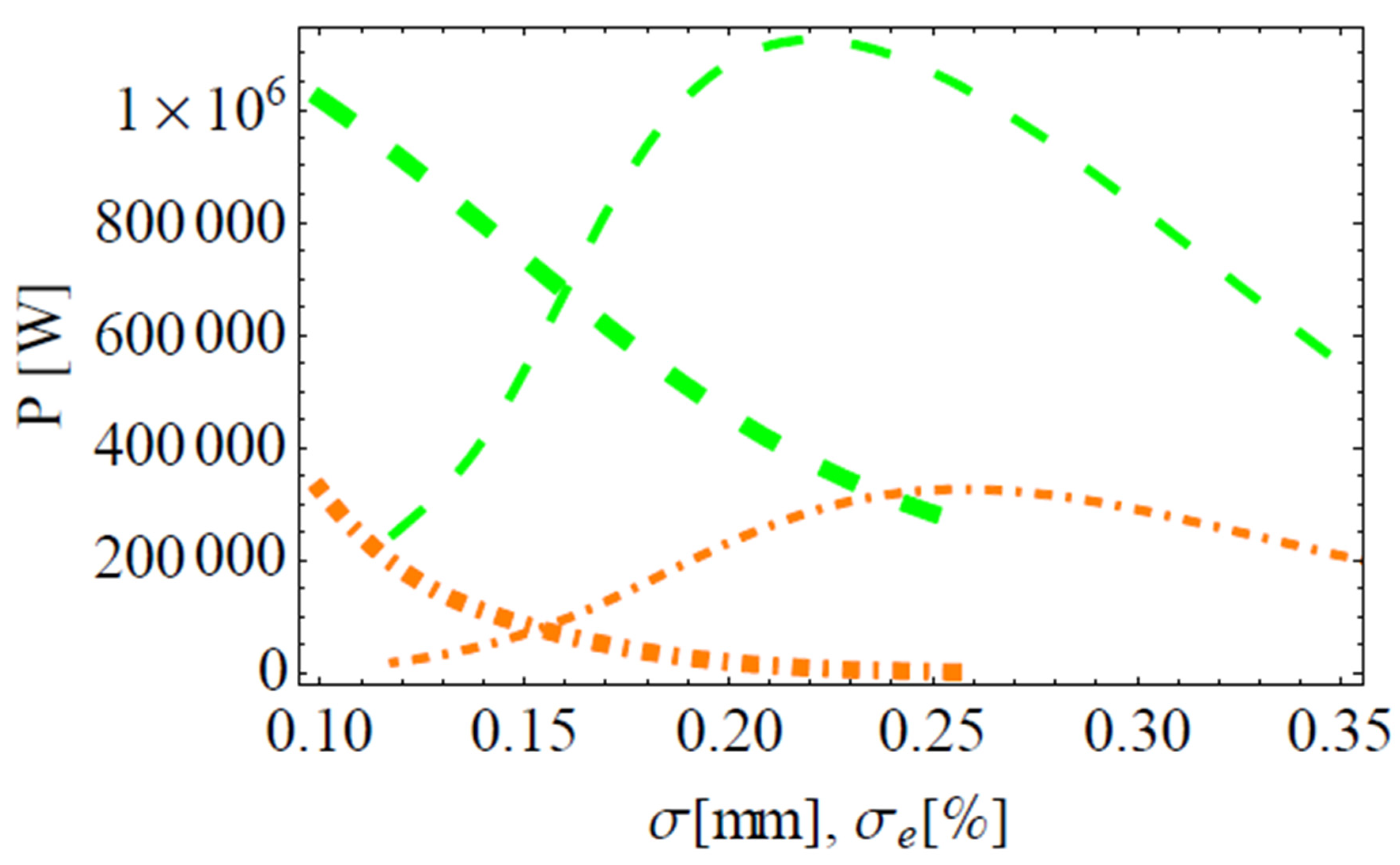
The increase in the beam section σx,y first increases the effective angle  θ ¯  and then decreases it; the maximum of  θ ¯  is achieved around the experimental value of the beam section σx,y ~ 0.25 mm. The increase in energy spread σe, on the contrary, decreases the angle  θ ¯  linearly, and thus, its effect is opposite to that of the beam size σx,y for relatively narrow beam sections σx,y < 0.25 mm. The dependence of  θ ¯  on the energy spread,  θ ¯ σ e , is stronger for beams with a wider section (see Figure 3). For the calculation of saturated harmonic powers we used formula (11), accounting for (12)−(14), which had been carefully calibrated with the data from all major operating FELs in the range from visible light to X-rays; so, our theoretical results describe all major FEL experiments worldwide [47,48,49,50,51,52]. The dependence of the attained saturated power on the beam parameters is complex (see (11)). Despite the fact that the harmonics close to saturation are induced by the fundamental with the Pierce parameter ρ1, the saturated powers of FEL harmonics involve their Bessel coefficients (2), (3) and phenomenological loss coefficients (12). The dependence of saturated powers of the second and third FEL harmonics on the beam section and on the energy spread is demonstrated in Figure 4. Note in Figure 4, the variation of the beam section influences the powers of FEL harmonics in a different way from that which the energy spread does. Both second and third harmonics are at their maximum powers (thin lines in Figure 4) for the beam section σx,y ~ 0.2−0.3 mm. For very large and small sections and fixed emittance, the harmonic powers decrease. The increase in energy spread decreases the powers of FEL harmonics: for the default LEUTL beam section σx,y ~ 0.25 mm, the saturated third harmonic power decreases 2−3 times (thick green line in Figure 4) and the second FEL harmonic is suppressed by one order of magnitude or more (thick orange line in Figure 4) if the beam energy spread is increased to σe = 0.2−0.25%. The increase in energy spread is limited by σe = 0.0025 due to the Pierce parameter value ρ1 ≈ 0.0025.
The FEL output powers are plotted on a logarithmic scale of all harmonics for the LEUTL beam section in Figure 5. Expectedly, all harmonic powers, including the fundamental, decrease with the increase in the beam section; the main reason for it is that the current density decreases in this case and it reduces the Pierce parameter. The decrease in FEL harmonic powers for small beam sections is explained by the emittance being kept constant and the decrease in the beam section being compensated by an increase in divergence. A very small section means very high divergence, which negatively affects FEL performance. This shows that low emittance itself is not sufficient to guarantee optimal operation of an FEL, and for the same emittance, different sections can provide better or worse operation conditions. The beam section σx,y ≈ 250 nm is default for LEUTL, and indeed, in Figure 5, we see that it corresponds to the maximum FEL radiation power and harmonic powers; the optimal balance of the section and divergence is achieved at this point for given beam emittance γεx,y = 6.2 π mm × mrad. The optimal section value was chosen by the engineers of LEUTL; it can be identified in Figure 5, and this fact indirectly confirms the correct modeling of the underlying physics and relevant effects in our approach.
In Figure 6, we demonstrate the behaviors of LEUTL FEL harmonic powers for a variation in beam energy spread.
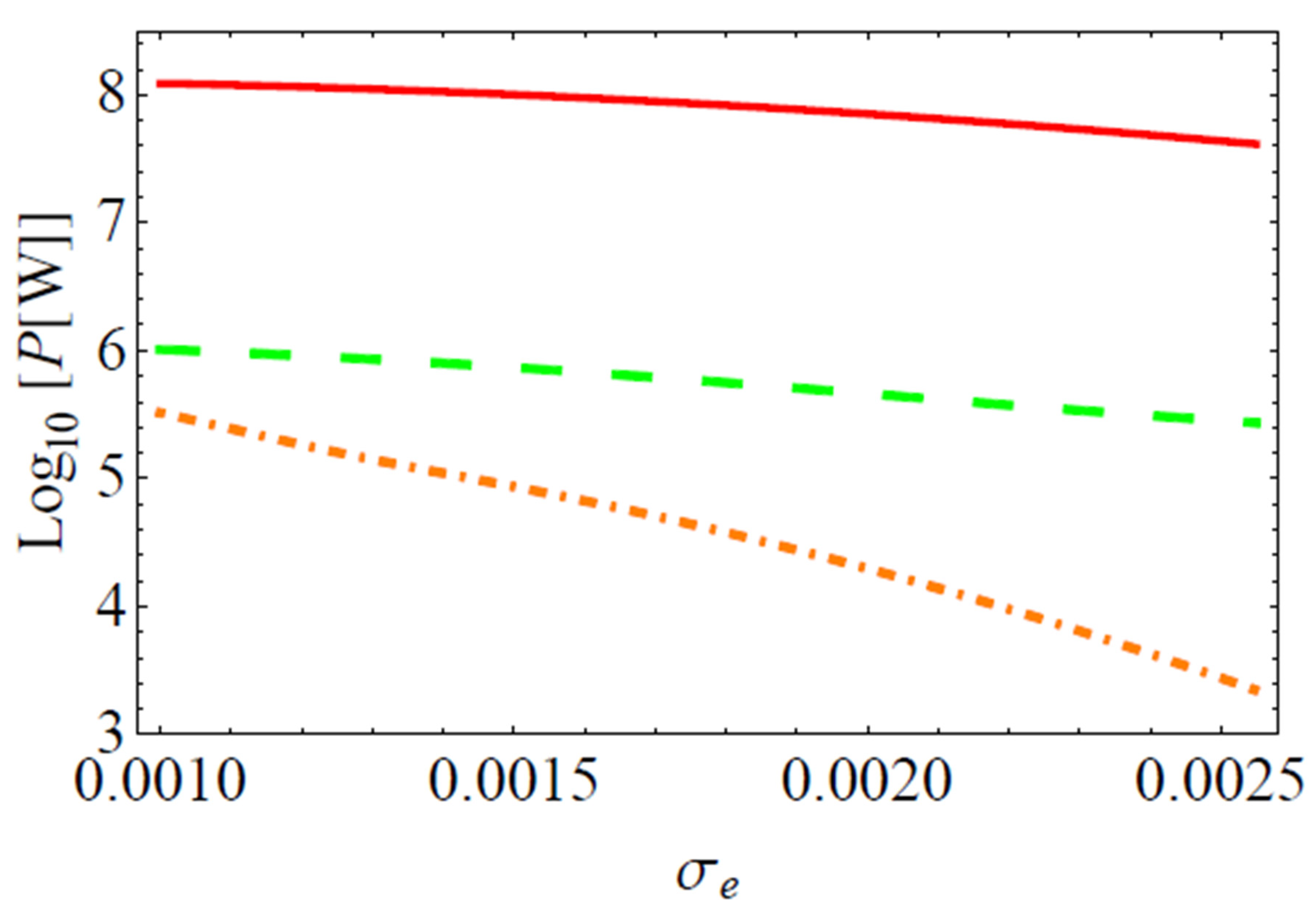
Expectedly, FEL power decreases with an increase in the energy spread. The strongest decrease experiences the second FEL harmonic (see orange dash-dotted line in Figure 6). The reasons for that are similar to those discussed with regard to the behaviors of the Bessel coefficients in Figure 1. The saturated harmonic power (11), induced by the fundamental in the nonlinear generation, depends on the coupling of electrons with the fundamental at its wavelength, and thus, the Pierce parameter ρ1 matters and not ρ2,3. However, the saturated harmonic power is also determined by the Bessel coefficients fn and the losses for the harmonic n. The second FEL harmonic radiation is mainly due to the angular effects of the beam; the effective angle of electron–photon interactions  θ ¯ σ x , y / L g a i n  is the largest angular contribution and it decreases (see Figure 3) if the energy spread increases, causing an increase in the gain (see Figure 2). The Bessel coefficient f2 also decreases with an increase in energy spread (see Figure 1), while f1,3 remain almost constant and do not sense the energy spread. This explains the high sensitivity of the second harmonic to losses, energy spread in particular.
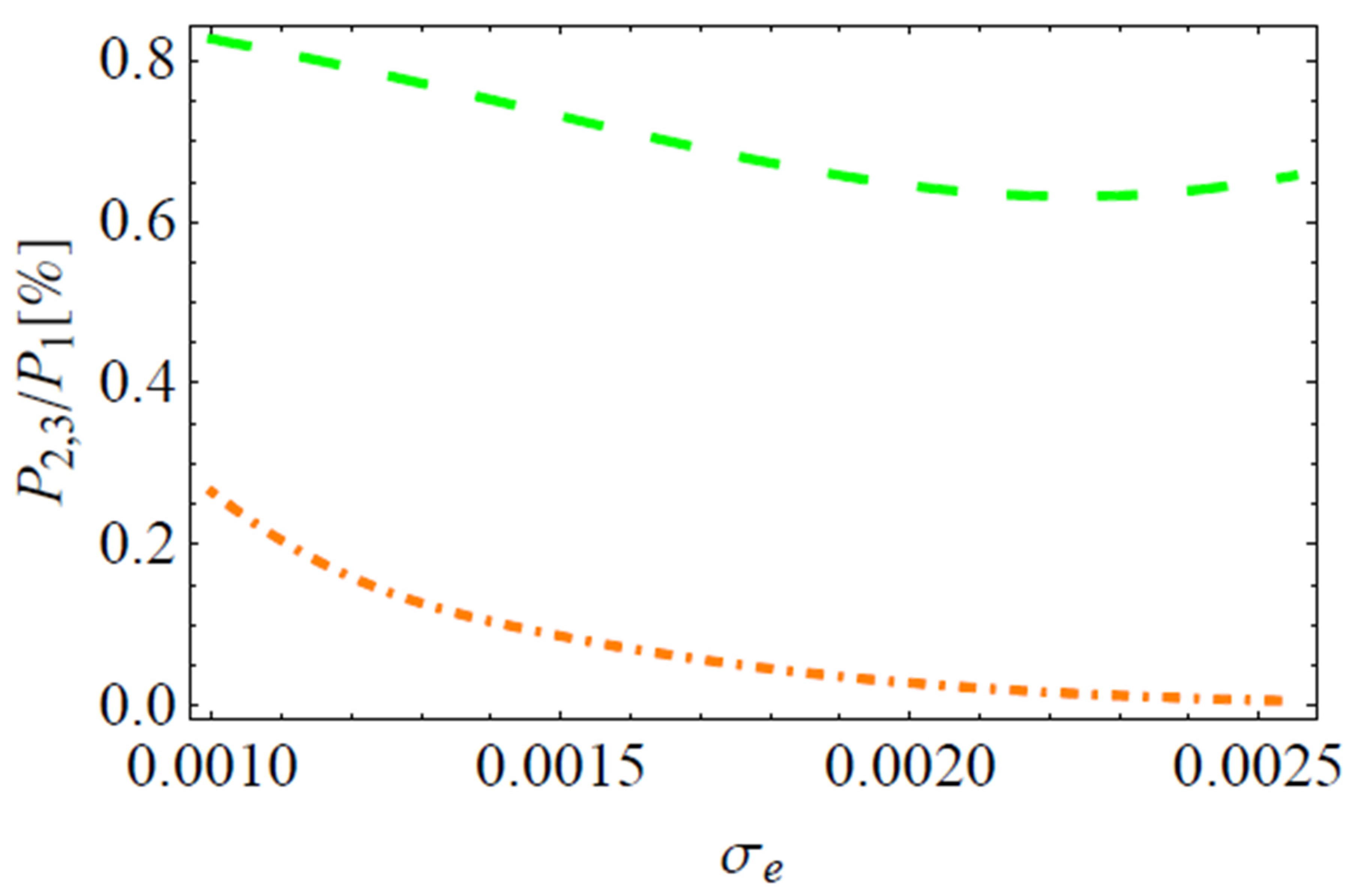
In Figure 7, we present the dependence of the harmonic content of LEUTL FEL on beam energy spread. The content of the third harmonic is shown by the green dashed line, and it slightly reduces with the increase in energy spread. The content of the second harmonic is shown by the orange dot-dashed line, and it rapidly decreases with the increase in energy spread. The decrease in second harmonic content is about of an order of magnitude for the energy spread increase from default σe = 0.1% to σe = 0.2%; the second harmonic content decreases ~two orders of magnitude for the increased energy spread σe = 0.25% (see Figure 7). Note that harmonic power oscillates and keeps growing slowly in saturation, and this makes it very difficult to quantify its exact changes. Even 3D numerical simulations have more than one order of magnitude margin of error for the harmonics.
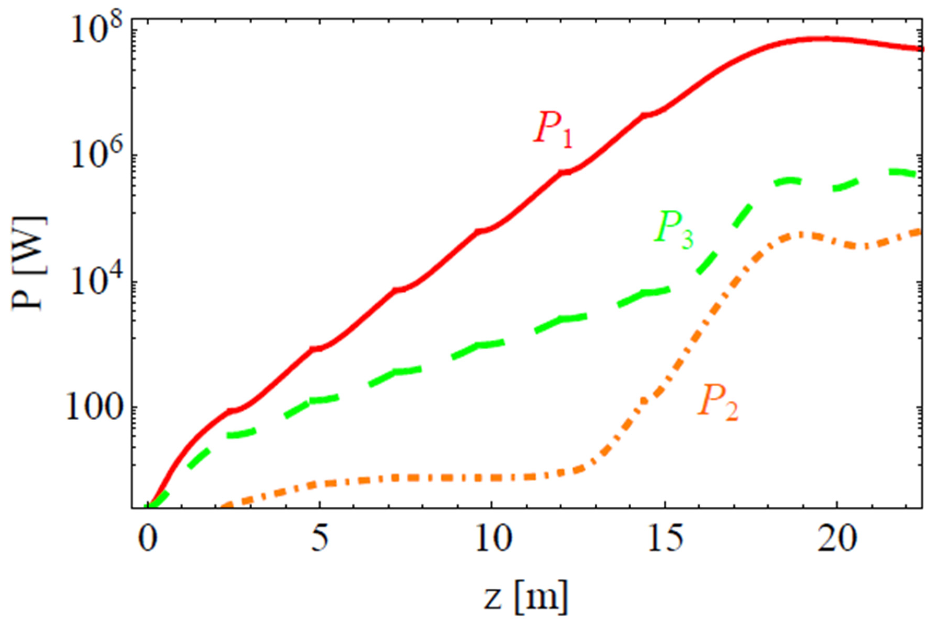
Now let us consider the influence of the beam energy spread and section on the evolution of FEL harmonics along the undulators. Close to saturation, FEL harmonics are induced by the fundamental, and their power grows as the n-th power of the fundamental. Thus, the dependence of the growth in harmonics on the beam parameters is determined by the dependence of the fundamental. Indeed, we have plotted the evolution of harmonic powers along the undulators for the beam energy spreads σe = 1 × 10⁻³ and σe = 2 × 10⁻³, respectively, in Figure 8 and in Figure 9. Higher energy spread extends the gain (see Figure 2) and extends the saturation length of LEUTL from Ls~15 m for the default energy spread σe = 1 × 10⁻³ (see Figure 8) to Ls~20 m for higher energy spread σe = 2 × 10⁻³ (see Figure 9). This causes some slower growth of all FEL harmonics, which, nevertheless, occurs in a similar way (compare Figure 8 vs. Figure 9). Thus, large energy spread of the beam does not change the power growth law for FEL harmonics in their nonlinear regime: harmonics grow as the n-th power of the fundamental. However, energy spread affects FEL gain; FEL harmonics sense it through the n-th power even more than the fundamental, and because of that, nonlinear harmonic growth is less steep in Figure 9 than in Figure 8. Note that the orange line of the second harmonic power in the nonlinear regime after 10 m in Figure 8 grows faster than it does in Figure 9 after 13 m.
At the same time, independent from fundamental, linear harmonic growth also suffers significantly high energy spread, which extends the gain length of FEL harmonics. This can be noticed for the third FEL harmonic as the respective green line before 13 m grows faster in Figure 8 than in Figure 9. For the second FEL harmonic in the independent evolution, the orange line before 10 m grows faster in Figure 8 than in Figure 9, where the energy spread is higher.
In Figure 8, we also show the experimentally measured values in the LEUTL experiment measured in August 2001 (see [31]), which is well described by our theoretical results (see Figure 8) along LEUTL undulators. The horizontal orange line after 17 m shows the average of the second harmonic power P2P1/240 for experiments reported in [31]. Dots show the measurements of the fundamental and second harmonic in the specific experiment, and the green area shows the range of the third harmonic power in saturation.

2. Results and Conclusions

We have employed an analytical model of FEL radiation and studied the behaviors of FEL gain, the Bessel coefficients, and some other quantities for a description of the harmonic powers in an FEL. We have explored the influence of beam energy spread and the beam section on FEL characteristics and on the radiation of FEL harmonics. The employed analytical formulae have been previously verified and calibrated with all major FELs operating in the range from visible light to X-rays. This study was applied to LEUTL FEL with the goal to estimate the best way to reduce the radiation of the second FEL harmonic.
The effect of the energy spread and beam section on the gain is nonlinear. Variation of the energy spread has a significant effect on FEL gain, especially if the beam section is large; for a narrow beam, the variation of the energy spread somehow does not cause a significant change in FEL gain length. The physical cause for this still has to be clarified in forthcoming research.
We have shown that the Bessel coefficients for odd harmonics are not sensitive to beam characteristics. The Bessel coefficient for the second FEL harmonic, on the contrary, increases with an increase in the beam section and decreases with an increase in energy spread.
We have found that the effective angle of the electron–photon interaction in the beam section on gain length grows to a point with an increase in the beam section. The angle decreases with an increase in the energy spread, and this behavior is more pronounced for large beam sections. This angle largely determines radiation of even harmonics in an FEL.
We have theoretically found that LEUTL FEL radiation power for all harmonics is at its maximum for an electron beam section of σx,y~250 nm, which is default for LEUTL FEL installation. At this section, the given beam emittance radiation is the strongest. A beam with a small section has a large divergence and it deteriorates FEL performance; a large beam section means low current density and weaker bunching, longer gain and lower power.
For LEUTL FEL, the beam energy spread can be increased from the default value of σe = 1 × 10⁻³ to the maximum value of σe ≈ 2−2.5 × 10⁻³ since the Pierce parameter is ρ ≈ 2.6 × 10⁻³. The influence of energy spread variation on the nonlinear generation and growth of the second harmonic occurs via the second power of the fundamental. Thus, the second harmonic senses the extended FEL gain more than the fundamental. The independent growth of harmonics in the first part of the FEL relies on the already weak interaction of electrons with radiation at the harmonic wavelength; this interaction becomes weaker with increased energy spread.
The power of the second harmonic in its nonlinear generation around and in saturation rapidly decreases with an increase in energy spread. The associated increase in gain length makes angular contributions smaller, and together with higher losses, this determines the second harmonic power reduction. The increase in energy spread twice from the default value to σe ≈ 2 × 10⁻³ reduces the second FEL harmonic saturated power by an order of magnitude. A further energy spread increase to σe > 2.5 × 10⁻³ suppresses the second harmonic up to two orders of magnitude. In comparison, the second field harmonic of the undulator with an amplitude ≈10% of the main field is expected to reduce the second harmonic power in LEUTL FEL ~5−7 times. From our analysis of proper contributions in our model, we conclude that the reduction in saturated power of the second harmonic is due to a combination of effects, among which the extension of the gain and decrease in angular contributions play major roles, expressed in the Bessel coefficients; losses, associated with the increased energy spread, also contribute negatively to the harmonic power. Eventually, a weaker coupling of electrons to radiation at harmonic wavelengths is more sensitive to losses, such as the energy spread.
In the present study, we have shown that an increased beam energy spread affected both the evolution of harmonics along the undulators of LEUTL and saturated FEL harmonic powers; we have found it is possible to suppress the second FEL harmonic with an increased beam energy spread. While the suggested values of the spread are custom for this installation, the method in general is valid for any FEL also in the X-ray band. The suggested reduction in the second FEL harmonic power can facilitate the analysis and understanding of the nonlinear second harmonic response from matter, where the SHG is not to be contaminated by background radiation at the same wavelength. However, the range of increases in energy spread is limited by the value σe~ρ; moreover, higher energy spread is associated with longer gain and an increased length of installation due to the necessity of longer undulators for saturation.

Funding

The author acknowledges support from the Russian Ministry of Science and Education under grant No. 075-15-2021-1353 and the Hungarian Office for Research, Development and Innovation (NKFIH) under project number 2022-2.1.1-NL-2022-00002.

Data Availability Statement

The data that support the findings of this study are available within the article.

Conflicts of Interest

The author declares no conflict of interest.

References

  1. Faatz, B.; Braune, M.; Hensler, O.; Honkavaara, K.; Kammering, R.; Kuhlmann, M.; Ploenjes, E.; Roensch-Schulenburg, J.; Schneidmiller, E.; Schreiber, S.; et al. The FLASH Facility: Advanced Options for FLASH2 and Future Perspectives. Appl. Sci. 2017, 7, 1114. [Google Scholar] [CrossRef]
  2. Schneidmiller, E.A.; Faatz, B.; Kuhlmann, M.; Rönsch-Schulenburg, J.; Schreiber, S.; Tischer, M.; Yurkov, M.V. First operation of a harmonic lasing self-seeded free electron laser. Phys. Rev. Accel. Beams 2017, 20, 020705. [Google Scholar] [CrossRef]
  3. Altarelli, M.; Brinkmann, R.; Chergui, M.; Decking, W.; Dobson, B.; Düsterer, S.; Grübel, G.; Graeff, W.; Graafsma, H.; Hajdu, J.; et al. (Eds.) XFEL: The European X-ray Free-Electron Laser—Technical Design Report; DESY 2006-097; DESY: Hamburg, Germany, 2006. [Google Scholar]
  4. Altarelli, M. The European X-ray free-electron laser facility in Hamburg. Nucl. Instrum. Methods Phys. Res. Sect. B Beam Interact. Mater. At. 2011, 269, 2845–2849. [Google Scholar] [CrossRef]
  5. Tschentscher, T.; Bressler, C.; Grünert, J.; Madsen, A.; Mancuso, A.P.; Meyer, M.; Scherz, A.; Sinn, H.; Zastrau, U. Photon Beam Transport and Scientific Instruments at the European XFEL. Appl. Sci. 2017, 7, 592. [Google Scholar] [CrossRef]
  6. Schneidmiller, E.A.; Yurkov, M.V. An overview of the radiation properties of the European XFEL. In Proceedings of the FEL 2014 Conference, Basel, Switzerland, 5–29 August 2014. [Google Scholar]
  7. Schneidmiller, E.A.; Yurkov, M.V. Photon Beam Properties at the European XFEL. Available online: https://inis.iaea.org/collection/NCLCollectionStore/_Public/42/096/42096439.pdf (accessed on 1 July 2023).
  8. Togashi, T.; Takahashi, E.J.; Midorikawa, K.; Aoyama, M.; Yamakawa, K.; Sato, T.; Iwasaki, A.; Owada, S.; Okino, T.; Yamanouchi, K.; et al. Extreme ultraviolet free electron laser seeded with high-order harmonic of Ti:sapphire laser. Opt. Express 2010, 19, 317–324. [Google Scholar] [CrossRef]
  9. Kang, H.-S.; Min, C.-K.; Heo, H.; Kim, C.; Yang, H.; Kim, G.; Nam, I.; Baek, S.Y.; Choi, H.-J.; Mun, G.; et al. Hard X-ray free-electron laser with femtosecond-scale timing jitter. Nat. Photonics 2017, 11, 708–713. [Google Scholar] [CrossRef]
  10. Yang, H.; Kim, G.; Kang, H.-S. First saturation of 14.5 keV free electron laser at PAL-XFEL. Nucl. Instrum. Methods Phys. Res. Sect. A Accel. Spectrometers Detect. Assoc. Equip. 2018, 911, 51–54. [Google Scholar] [CrossRef]
  11. Hong, J.; Han, J.-H.; Park, S.; Jung, Y.; Kim, D.; Kang, H.-S.; Pflueger, J. A study on low emittance injector and undulator for PAL-XFEL. High Power Laser Sci. Eng. 2015, 3, e21. [Google Scholar] [CrossRef]
  12. Ko, I.S.; Kang, H.-S.; Heo, H.; Kim, C.; Kim, G.; Min, C.-K.; Yang, H.; Baek, S.Y.; Choi, H.-J.; Mun, G.; et al. Construction and Commissioning of PAL-XFEL Facility. Appl. Sci. 2017, 7, 479. [Google Scholar] [CrossRef]
  13. Emma, P.; Akre, R.; Arthur, J.; Bionta, R.; Bostedt, C.; Bozek, J.; Brachmann, A.; Bucksbaum, P.; Coffee, R.; Decker, F.-J.; et al. First lasing and operation of an angstrom-wavelength free-electron laser. Nat. Photonics 2010, 4, 641–647. [Google Scholar] [CrossRef]
  14. Emma, P. First lasing of the LCLS X-ray FEL at 1.5 Å, TH3PBI01. In Proceedings of the 23rd Conference PAC09, Vancouver, BC, Canada, 4–8 May 2009. [Google Scholar]
  15. Huang, Z.; Reiche, S. Generation of GW-level, sub-Angstrom radiation in the LCLS using a second-harmonic radiator. In Proceedings of the FEL 2004 Conference, Trieste, Italy, 29 August–3 September 2004; p. 201. [Google Scholar]
  16. Ratner, D.; Brachmann, A.; Decker, F.J.; Ding, Y.; Dowell, D.; Emma, P.; Fisher, A.; Frisch, J.; Gilevich, S.; Huang, Z.; et al. Second and third harmonic measurements at the linac coherent light source. Phys. Rev. Spéc. Top. Accel. Beams 2011, 14, 060701. [Google Scholar] [CrossRef]
  17. Milne, C.J.; Schietinger, T.; Aiba, M.; Alarcon, A.; Alex, J.; Anghel, A.; Arsov, V.; Beard, C.; Beaud, P.; Bettoni, S.; et al. SwissFEL: The Swiss X-ray Free Electron Laser. Appl. Sci. 2017, 7, 720. [Google Scholar] [CrossRef]
  18. Abela, R.; Beaud, P.; van Bokhoven, J.A.; Chergui, M.; Feurer, T.; Haase, J.; Ingold, G.; Johnson, S.L.; Knopp, G.; Lemke, H.; et al. Perspective: Opportunities for ultrafast science at SwissFEL. Struct. Dyn. 2017, 4, 061602. [Google Scholar] [CrossRef] [PubMed]
  19. Juranić, P.; Rehanek, J.; Arrell, C.A.; Pradervand, C.; Ischebeck, R.; Erny, C.; Heimgartner, P.; Gorgisyan, I.; Thominet, V.; Tiedtke, K.; et al. SwissFEL Aramis beamline photon diagnostics. J. Synchrotron Radiat. 2018, 25, 1238–1248. [Google Scholar] [CrossRef] [PubMed]
  20. Juranić, P.; Rehanek, J.; Arrell, C.A.; Pradervand, C.; Cassar, A.; Calvi, M.; Ischebeck, R.; Erny, C.; Heimgartner, P.; Gorgisyan, I.; et al. SwissFEL Aramis beamline photon diagnostics. Erratum. J. Synchrotron Radiat. 2019, 26, 906. [Google Scholar] [CrossRef] [PubMed]
  21. Abela, R.; Alarcon, A.; Alex, J.; Arrell, C.; Arsov, V.; Bettoni, S.; Bopp, M.; Bostedt, C.; Braun, H.-H.; Calvi, M.; et al. The SwissFEL soft X-ray free-electron laser beamline: Athos. J. Synchrotron Rad. 2019, 26, 1073–1084. [Google Scholar] [CrossRef] [PubMed]
  22. Prat, E.; Abela, R.; Aiba, M.; Alarcon, A.; Alex, J.; Arbelo, Y.; Arrell, C.; Arsov, V.; Bacellar, C.; Beard, C.; et al. A compact and cost-effective hard X-ray free-electron laser driven by a high-brightness and low-energy electron beam. Nat. Photon. 2020, 14, 748–754. [Google Scholar] [CrossRef]
  23. Inoue, I.; Osaka, T.; Hara, T.; Tanaka, T.; Inagaki, T.; Fukui, T.; Goto, S.; Inubushi, Y.; Kimura, H.; Kinjo, R.; et al. Generation of narrow-band X-ray free-electron laser via reflection self-seeding. Nat. Photon. 2019, 13, 319–322. [Google Scholar] [CrossRef]
  24. Owada, S.; Nakajima, K.; Togashi, T.; Kayatama, T.; Yabashi, M. Single-shot arrival timing diagnostics for a soft X-ray free-electron laser beamline at SACLA. J. Synchrotron Rad. 2018, 25, 282. [Google Scholar] [CrossRef]
  25. Tetsuya, I.; Hideki, A.; Takao, A.; Yoshihiro, A.; Noriyoshi, A.; Teruhiko, B.; Hiroyasu, E.; Kenji, F.; Toru, F.; Yukito, F.; et al. A compact X-ray free-electron laser emitting in the sub-ångström region. Nat. Photon. 2012, 6, 540–544. [Google Scholar]
  26. Available online: http://xfel.riken.jp/eng/users/bml02-11.html (accessed on 1 July 2023).
  27. Ego, H.; Asaka, T.; Fujita, T.; Fukui, T.; Hosoda, N.; Inagaki, T.; Kobayashi, K.; Kondo, C.; Maesaka, H.; Masuda, T.; et al. RF System of the SPring-8 Upgrade Project. In Proceedings of the IPAC2016, Busan, Korea, 8–13 May 2016; pp. 414–416. [Google Scholar]
  28. Iwai, E.; Inoue, I.; Maesaka, H.; Inagaki, T.; Yabashi, M.; Hara, T.; Tanaka, H. Spectral-brightness optimization of an X-ray free-electron laser by machine-learning-based tuning. J. Synch. Rad. 2023, 30, 1048–1053. [Google Scholar] [CrossRef]
  29. Tono, K.; Hara, T.; Yabashi, M.; Tanaka, H. Multiple-beamline operation of SACLA. J. Synchrotron Rad. 2019, 26, 595–602. [Google Scholar] [CrossRef] [PubMed]
  30. Tono, K.; Togashi, T.; Inubushi, Y.; Sato, T.; Katayama, T.; Ogawa, K.; Ohashi, H.; Kimura, H.; Takahashi, S.; Takeshita, K.; et al. Beamline, experimental stations and photon beam diagnostics for the hard x-ray free electron laser of SACLA. New J. Phys. 2013, 15, 083035. [Google Scholar] [CrossRef]
  31. Biedron, S.G.; Dejus, R.J.; Huang, Z.; Milton, S.V.; Sajaev, V.; Berg, W.; Borland, M.; DenHartog, P.K.; Erdmann, M.; Fawley, W.M.; et al. Measurements of nonlinear har-monic generation at the Advanced Photon Source’s SASE FEL. Nucl. Instrum. Meth. Phys. Res. A 2002, 483, 94–100. [Google Scholar] [CrossRef]
  32. Milton, S.V.; Gluskin, E.; Arnold, N.D.; Benson, C.; Berg, W.; Biedron, S.G.; Borland, M.; Chae, Y.C.; Dejus, R.J.; Den Hartog, P.K.; et al. Exponential Gain and Saturation of a Self-AmpliÞed Spontaneous Emission Free-Electron Laser. Science 2000, 292, 2037–2041. [Google Scholar] [CrossRef] [PubMed]
  33. Alfonso, F.; Maya, K. Elettra-Sincrotrone Trieste: Present and future. Eur. Phys. J. Plus 2023, 79, 138. [Google Scholar]
  34. Xiao, R.; Chen, K.; Shi, Y.; Chen, C. Toward 80% Efficiency in a Super Klystron-Like Relativistic Backward Wave Oscillator With Second and Third Harmonic Coaxial-Premodulation Cavity. IEEE Trans. Electron Devices 2023, 70, 2521–25251. [Google Scholar] [CrossRef]
  35. Kuznetsov, S.V.; Sedov, V.S.; Martyanov, A.K.; Batygov, S.C.; Vakalov, D.S.; Boldyrev, K.N.; Tiazhelov, I.A.; Popovich, A.F.; Pasternak, D.G.; Bland, H.; et al. Cerium-doped gadolinium-scandium-aluminum garnet powders: Synthesis and use in X-ray luminescent diamond composites. Ceram. Int. 2022, 48, 12962–12970. [Google Scholar] [CrossRef]
  36. Sedov, V.; Kuznetsov, S.; Kamenskikh, I.; Martyanov, A.; Vakalov, D.; Savin, S.; Rubtsova, E.; Tarala, V.; Omelkov, S.; Kotlov, A.; et al. Diamond composite with embedded YAG:Ce nanoparticles as a source of fast X-ray luminescence in the visible and near-IR range. Carbon 2021, 174, 52–58. [Google Scholar] [CrossRef]
  37. Kuznetsov, S.V.; Yasyrkina, D.S.; Valiev, D.T.; Stepanov, S.A.; Alexandrov, A.A.; Batygov, S.K.; Voronov, V.V.; Konyushkin, V.A.; Nakladov, A.N.; Ermakova, J.A.; et al. Spectral and Cathodoluminescence Decay Characteristics of the Ba1−xCexF2+x (x = 0.3–0.4) Solid Solution Synthesized by Precipitation from Aqueous Solutions and Fusion. Photonics 2023, 10, 1057. [Google Scholar] [CrossRef]
  38. Kuznetsov, S.V.; Ermakova, Y.A.; Boldyrev, K.N.; Sedov, V.S.; Alexandrov, A.A.; Voronov, V.V.; Batygov, S.K.; Rezaeva, A.D.; Drobysheva, A.R.; Tabachkova, N.Y. Single-phase nanopowders of Sr0.85-xBaxEu0.15F2.15: Investigation of structure and X-ray luminescent properties. Ceram. Int. 2023, 49, 39189–39195. [Google Scholar] [CrossRef]
  39. Wu, L.; Patankar, S.; Morimoto, T.; Nair, N.L.; Thewalt, E.; Little, A.; Analytis, J.G.; Moore, J.E.; Orenstein, J. Giant anisotropic nonlinear optical response in transition metal monopnictide Weyl semimetals. Nat. Phys. 2016, 13, 350–355. [Google Scholar] [CrossRef]
  40. Nuriya, M.; Fukushima, S.; Momotake, A.; Shinotsuka, T.; Yasui, M.; Arai, T. Multimodal two-photon imaging using a second harmonic generation-specific dye. Nat. Commun. 2016, 7, 11557. [Google Scholar] [CrossRef] [PubMed]
  41. Campagnola, P.J.; Loew, L.M. Second-harmonic imaging microscopy for visualizing biomolecular arrays in cells, tissues and organisms. Nat. Biotechnol. 2003, 21, 1356–1360. [Google Scholar] [CrossRef] [PubMed]
  42. Boyd, G.; Bridges, T.; Burkhardt, E. Up-Conversion of 10.6 p Radiation to the Visible and Second Harmonic Generation in HgS. IEEE J. Quantum Electron. 1968, 4, 515. [Google Scholar] [CrossRef]
  43. Bhar, G.C.; Das, S.; Vodopyanov, K.L. Nonlinear optical laser devices using GaSe. Appl. Phys. B Laser Opt. 1995, 61, 187–190. [Google Scholar] [CrossRef]
  44. Csonka, P.L.; Kroo, N. Methods to generate femto- and attosecond electron and X-ray pulses. Nucl. Instrum. Methods Phys. Res. Sect. A 1996, 376, 283–290. [Google Scholar] [CrossRef]
  45. Zhukovsky, K.; Fedorov, I. Spontaneous and Stimulated Undulator Radiation in Symmetric and Asymmetric Multi-Periodic Magnetic Fields. Symmetry 2021, 13, 135. [Google Scholar] [CrossRef]
  46. Zhukovsky, K.V. Effect of the 3rd undulator field harmonic on spontaneous and stimulated undulator radiation. J. Synchrotron Rad. 2019, 26, 1481. [Google Scholar] [CrossRef]
  47. Zhukovsky, K. Analysis of the spectral properties of free electron lasers in X-ray and other bands. Radiat. Phys. Chem. 2021, 189, 109698. [Google Scholar] [CrossRef]
  48. Zhukovsky, K. Theoretical analysis of the radiation properties of some major x-ray free electron lasers. Ann. Phys. 2021, 533, 2100091. [Google Scholar] [CrossRef]
  49. Zhukovsky, K.; Fedorov, I. On the Generation of Even Harmonics in Planar and Elliptical Undulators of Free Electron Lasers. Mosc. Univ. Phys. Bull. 2022, 77, 11. [Google Scholar] [CrossRef]
  50. Zhukovsky, K.V. Undulator and free-electron laser radiation with field harmonics and off-axis effects taken into account analytically. Phys. Uspekhi 2021, 64, 304–316. [Google Scholar] [CrossRef]
  51. Zhukovsky, K. On the possibilities of amplification and radiation of harmonics in modern X-ray free electron lasers. Opt. Laser Technol. 2021, 143, 107296. [Google Scholar] [CrossRef]
  52. Zhukovsky, K.V. Theoretical Analysis of Radiation Properties of X-ray Free-Electron Lasers. Radiophys. Quantum Electron. 2022, 65, 88–117. [Google Scholar] [CrossRef]
  53. Prakash, B.; Huse, V.; Gehlot, M.; Mishra, G. Analysis of spectral properties of harmonic undulator radiation of an electromagnet undulator. Optik 2016, 127, 1639. [Google Scholar] [CrossRef]
  54. Attwood, D. Soft X-rays and Extreme Ultraviolet Radiation; Cambridge University Press: Cambridge, UK, 1999; Chapter 5. [Google Scholar]
  55. Kitamura, H. Polarization of Undulator Radiation. Jpn. J. Appl. Phys. 1980, 19, L185–L188. [Google Scholar] [CrossRef]
  56. Vinokurov; Levichev, E.B. Undulators and wigglers for the production of radiation and other applications. Phys. Uspekhi 2015, 58, 850. [Google Scholar] [CrossRef]
  57. Alferov, D.F.; Bashmakov, Y.A.; Cherenkov, P.A. Radiation from relativistic electrons in a magnetic undulator. Sov. Phys. Uspekhi 1989, 32, 200. [Google Scholar] [CrossRef]
  58. Zhukovsky, K. JETP, On the Possibility of Controlling the Second Harmonic Radiation of the Free Electron Laser Using the Second Harmonic of the Undulator Field. J. Exp. Theor. Phys. 2023, 137, 271. [Google Scholar] [CrossRef]
  59. Tanaka, T.; Kitamura, H. SPECTRA: A synchrotron radiation calculation code. J. Synchrotron Rad. 2001, 8, 1221–1228. [Google Scholar] [CrossRef]
  60. Tanaka, T. Numerical methods for characterization of synchrotron radiation based on the Wigner function method. Phys. Rev. ST Accel. Beams 2014, 17, 060702. [Google Scholar] [CrossRef]
  61. Tanaka, T. Coherent mode decomposition using mixed Wigner functions of Hermite–Gaussian beams. Opt. Lett. 2017, 42, 1576. [Google Scholar] [CrossRef] [PubMed]
  62. Tanaka, T. Universal representation of undulator phase errors. Phys. Rev. Accel. Beams 2018, 21, 110704. [Google Scholar] [CrossRef]
  63. Zhukovsky, K.; Fedorov, I.; Gubina, N. Theoretical analysis of the influence of electron beam parameters on the harmonic powers in free electron lasers. Opt. Laser Technol. 2023, 159, 108972. [Google Scholar] [CrossRef]
  64. McNeil BW, J.; Thompson, N.R. X-ray free-electron lasers. Nat. Photonics 2010, 4, 814. [Google Scholar] [CrossRef]
  65. Pellegrini, C.; Marinelli, A.; Reiche, S. The physics of x-ray free-electron lasers. Rev. Mod. Phys. 2016, 88, 015006. [Google Scholar] [CrossRef]
  66. Margaritondo, G. Synchrotron light: A success story over six decades. Riv. Nuovo Cimento. 2017, 40, 411–471. [Google Scholar]
  67. Huang, Z.; Kim, K.-J. Review of X-ray free-electron laser theory. Phys. Rev. Spéc. Top. Accel. Beams 2007, 10, 034801. [Google Scholar] [CrossRef]
  68. Huang, Z.; Kim, K.-J. Three-dimensional analysis of harmonic generation in high-gain free-electron lasers. Phys. Rev. E 2000, 62, 7295–7308. [Google Scholar] [CrossRef]
  69. Huang, Z.; Kim, K.-J. Nonlinear harmonic generation of coherent amplification and self-amplified spontaneous emission. Nucl. Instrum. Methods Phys. Res. Sect. A 2001, 475, 112. [Google Scholar] [CrossRef]
  70. Saldin, E.L.; Schneidmiller, E.; Yurkov, M. The Physics of Free Electron Lasers; Springer-Verlag: Berlin/Heidelberg, Germany, 2000; 470p. [Google Scholar]
  71. Colson, W. Theory of high-gain free-electron lasers. Nucl. Instrum. Methods Phys. Res. Sect. A Accel. Spectrometers Detect. Assoc. Equip. 1997, 393, 82–85. [Google Scholar] [CrossRef]
  72. Freund, H.P.; O’Shea, P.G.; Biedron, S.G. Nonlinear harmonic generation in free-electron lasers. IEEE J. Quantum Electron. 2000, 36, 275. [Google Scholar] [CrossRef]
  73. Bonifacio, R.; Pellegrini, C.; Narducci, L. Collective instabilities and high-gain regime in a free electron laser. Opt. Commun. 1984, 50, 373–378. [Google Scholar] [CrossRef]
  74. Giannessi, L. Seeding and Harmonic Generation in Free-Electron Lasers. In Synchrotron Light Sources and Free-Electron Lasers; Jaeschke, E.J., Khan, S., Schneider, J.R., Hastings, J.B., Eds.; Springer International Publishing: Cham, Switzerland, 2016. [Google Scholar]
  75. Dattoli, G.; Giannessi, L.; Ottaviani, P.L.; Ronsivalle, C. Semi-analytical model of self-amplified spontaneous-emission free-electron lasers, including diffraction and pulse-propagation effects. J. Appl. Phys. 2004, 95, 3206–3210. [Google Scholar] [CrossRef]
  76. Dattoli, G.; Ottaviani, P.L.; Pagnutti, S. Nonlinear harmonic generation in high-gain free-electron lasers. J. Appl. Phys. 2005, 97, 113102. [Google Scholar] [CrossRef]
  77. Dattoli, G.; Ottaviani, P.L.; Pagnutti, S. Booklet for FEL Desing: A Collection of Practical Formulae; ENEA Report RT/2007/40/FIM; ENEA: Frascati, Italy, 2007. [Google Scholar]
  78. Dattoli, G.; Di Palma, E.; Licciardi, S.; Sabia, E. Free Electron Laser High Gain Equation and Harmonic Generation. Appl. Sci. 2020, 11, 85. [Google Scholar] [CrossRef]
  79. Xie, M. Exact and variational solutions of 3D eigenmodes in high gain FELs. Nucl. Instrum. Methods Phys. Res. Sect. A 2000, 445, 59. [Google Scholar] [CrossRef]
  80. Xie, M. Design Optimization for an X-Ray Free Electron Laser Driven by SLAC Linac. In Proceedings of the 1995 Particle Accelerator Conference, Dallas, TX, USA, 1–5 May 1995; IEEE: Piscataway, NJ, USA, 1995; p. 183. [Google Scholar]
  81. Zhukovsky, K.V. Analytical Description of Nonlinear Harmonic Generation Close to the Saturation Region in Free Electron Lasers. Mosc. Univ. Phys. Bull. 2019, 74, 480–487. [Google Scholar] [CrossRef]
  82. Zhukovsky, K. On the second harmonic generation in X-ray FELs. EPL 2023, 141, 45002. [Google Scholar] [CrossRef]
  83. Zhukovsky, K.; Kalitenko, A. Phenomenological and numerical analysis of power evolution and bunching in single-pass X-ray FELs. J. Synchrotron Radiat. 2019, 26, 159–169. [Google Scholar] [CrossRef] [PubMed]
  84. Gianessi, L. Overview of Perseo, a system for simulating FEL dynamics in Mathcad. In Proceedings of the 28th International Free Electron Laser Conference (FEL 2006), Berlin, Germany, 27 August–1 September 2006; pp. 91–94. [Google Scholar]
  85. Freund, H.P.; van der Slot, P.J.M. Variable polarization states in free-electron lasers. J. Phys. Commun. 2021, 5, 085011. [Google Scholar] [CrossRef]
  86. Geloni, G.; Saldin, E.; Schneidmiller, E.; Yurkov, M. Exact solution for second harmonic generation in XFELs. Opt. Commun. 2007, 271, 207–218. [Google Scholar] [CrossRef]
  87. Saldin, E.; Geloni, G.; Schneidmiller, E.; Yurkov, M.V. Misconceptions regarding Second Harmonic Generation in X-ray Free-Electron Lasers. Nucl. Instrum. Methods Phys. Res. Sect. A 2005, 539, 499. [Google Scholar] [CrossRef]
Figure 1. Bessel coefficients for the beam section,  f n σ x , y  for the default energy spread σe = 1 × 10⁻³ (thin lines) and for the energy spread  f n σ e  for the experimental section σx,y = 0.26 mm (thick lines) of LEUTL FEL; E = 217 MeV, λ1 = 532 nm, I0 = 210 A, γεx,y = 6.2 π mm × mrad. f1—solid red, f2—dash-dotted orange, f3—dashed green lines.
Symmetry 15 02180 g001
Figure 2. Gain length Lg for the energy spread and for the beam section at LEUTL FEL; E = 217 MeV, λ1 = 532 nm, I0 = 210 A, γεx,y = 6.2 π mm × mrad.
Symmetry 15 02180 g002
Figure 3. Effective angle of electron–photon interaction  θ ¯  for the energy spread and the beam section at LEUTL FEL; E = 217 MeV, λ1 = 532 nm, I0 = 210 A, γεx,y = 6.2 π mm × mrad.
Symmetry 15 02180 g003
Figure 4. The 2nd and 3rd FEL harmonic saturated powers for the beam section  P 2 , 3 σ x , y  (thin lines) for the spread σe = 1 × 10⁻³ and for the energy spread  P 2 , 3 σ e  (thick lines) for the section σx,y= 0.26 mm at LEUTL FEL; E = 217 MeV, λ1 = 532 nm, I0 = 210 A, γεx,y = 6.2 π mm × mrad. The harmonics: P2—dash-dotted orange, P3—dashed green lines.
Symmetry 15 02180 g004
Figure 5. Saturated harmonic powers for the beam section for the default experimental energy spread σe = 1 × 10⁻³ at LEUTL FEL; E = 217 MeV, λ1 = 532 nm, I0 = 210 A, γεx,y = 6.2 π mm × mrad. The harmonics: P1—solid red, P2—dash-dotted orange, P3—dashed green lines.
Symmetry 15 02180 g005
Figure 6. Saturated harmonic powers for the beam energy spread for the default experimental section σx,y ≈ 0.26 mm at LEUTL FEL; E = 217 MeV, λ1 = 532 nm, I0 = 210 A, γεx,y = 6.2 π mm × mrad. The harmonics: P1—solid red, P2—dash-dotted orange, P3—dashed green lines.
Symmetry 15 02180 g006
Figure 7. Harmonic content for the energy spread variation for σx,y = 0.26 mm at LEUTL FEL; E = 217 MeV, λ1 = 532 nm, I0 = 210 A. The harmonic content: P2/P1—dash-dotted orange, P3/P1—dashed green lines.
Symmetry 15 02180 g007
Figure 8. Evolution of the harmonic powers along LEUTL undulators in the experiment from August 2001 for default energy spread σe = 1 × 10⁻³; E = 217 MeV, λ1 = 532 nm, I0 = 210 A, σx,y = 0.26 mm, γεx,y = 6.2 π mm × mrad; the experimental harmonic powers are denoted by colored dots and green area for the 3rd harmonic; theoretical powers are denoted by lines: P1—solid red, P2—dash-dotted orange, P3—dashed green.
Symmetry 15 02180 g008
Figure 9. Evolution of the harmonic powers along LEUTL undulators for increased energy spread σe = 2 × 10⁻³; E = 217 MeV, λ1 = 532 nm, I0 = 210 A, σx,y = 0.26 mm, γεx,y = 6.2 π mm × mrad; the harmonics powers: P1—solid red, P2—dash-dotted orange, P3—dashed green lines.
Symmetry 15 02180 g009
Disclaimer/Publisher’s Note: The statements, opinions and data contained in all publications are solely those of the individual author(s) and contributor(s) and not of MDPI and/or the editor(s). MDPI and/or the editor(s) disclaim responsibility for any injury to people or property resulting from any ideas, methods, instructions or products referred to in the content.