Article

Thermal-Stress Coupling Optimization for Coaxial through Silicon Via

School of Microelectronics, Xidian University, Xi’an 710071, China
*
Authors to whom correspondence should be addressed.
Symmetry 2023, 15(2), 264; https://doi.org/10.3390/sym15020264
Submission received: 14 December 2022 / Revised: 6 January 2023 / Accepted: 17 January 2023 / Published: 17 January 2023
(This article belongs to the Section Computer)

Abstract

:
In this paper, a thermal-stress coupling optimization strategy for coaxial through silicon via (TSV) is developed based on the finite element method (FEM), artificial neural network (ANN) model and particle swarm optimization (PSO) algorithm. In order to analyze the effect of design parameters on the thermal-stress distribution of coaxial TSV, the FEM simulations of coaxial TSV are conducted by COMSOL Multiphysics. The structure of coaxial TSV is symmetric. The mapping relationships between the design parameters and performance indexes are described by ANN models based on the simulation data of FEM. In addition, the multi-objective optimization function is formulated based on the desired performance indexes, and then the design parameters are optimized by the modified PSO algorithm. Based on the optimized design parameters, the effectiveness of the developed method is validated by FEM simulations. The simulated performance indexes agree well with the desired ones, which implies that the design parameters of coaxial TSV can be optimized to control the thermal-stress distribution. Therefore, the thermal-stress coupling optimization of coaxial TSV can achieve thermal-stress management to improve its reliability.

1. Introduction

With the rapid development of the semiconductor industry, a high-reliability integrated system is required. Due to the advantages, such as high performance, high integrated density and low interconnect length, a three-dimensional (3D) integrated system [1,2,3,4] has become an effective technology for the development of integrated circuits beyond Moore’s law. In addition, through silicon via (TSV) [5,6,7] is adopted to achieve vertical interconnection between different integrated circuits. However, the TSV can generate thermal strain and stress during temperature changes, which leads to serious reliability problems for the 3D integrated system [8,9]. Therefore, it is valuable to develop an effective design method for coaxial TSV to improve its performance.
Due to the advantages, such as suppressing signal crosstalk, reducing transmission loss and signal transmission delay, coaxial TSV has been investigated by many researchers. Zhao et al. [10] proposed an equivalent lumped element circuit model of coaxial TSV, which can predict the characteristic impedance. Compared to the circular and square coaxial TSV, Zhao et al. [11] proposed an equivalent lumped element circuit model of coaxial TSV, which analyzed the parasitic capacitance value, characteristic impedance and s parameters under different frequencies and temperatures. In addition, Qian et al. [12] proposed a high-precision distributed transmission line model based on the extracted electrical parameters of coaxial TSV and finite element method (FEM). The effects of various material properties and physical parameters on the electrical performance of coaxial TSV are investigated by the developed method. Based on the FEM and experiment, Dixit et al. [13] analyzed the thermal strain and thermal deformation of the TSV structure under the temperature cycling condition of 25–125 °C. The experiment results show that the shear strain between the copper and silicon is the major potential factor affecting the reliability of TSV. Tsai et al. [14] investigated the thermal-stress distribution of TSV based on finite element analysis. The simulation results show that the maximum stress is increased by about 300 MPa as the diameter ratio increases from 0.6 to 0.9. In the traditional design method, the FEM software is used to obtain the design scheme through iterative computation and comparison. The traditional design methods based on FEM rely on the experts’ experience, and the design parameters cannot be effectively optimized to control the thermal-stress distribution of TSV. Therefore, the thermal-stress coupling optimization should be investigated to control the thermal-stress distributions and further improve the reliability of coaxial TSV.
Recently, the artificial neural network (ANN), has been widely used in the model predicted control [15,16,17], image processing [18,19,20] and optimization algorithms [21,22,23]. In addition, the particle swarm optimization (PSO) algorithm has been utilized in the topology optimization for compliant mechanisms [24,25], the optimal design parameters of electronic components [26] and the optimal parameters of the filtering algorithm [27,28]. Therefore, the PSO algorithm can be adopted to obtain the optimal design parameters of coaxial TSV based on the thermal-stress coupling physics field for high-efficiency thermal-stress management.
In this paper, a thermal-stress coupling optimization of coaxial TSV is proposed to control the thermal-stress distribution. The novelty can be summarized as follows:
(1)
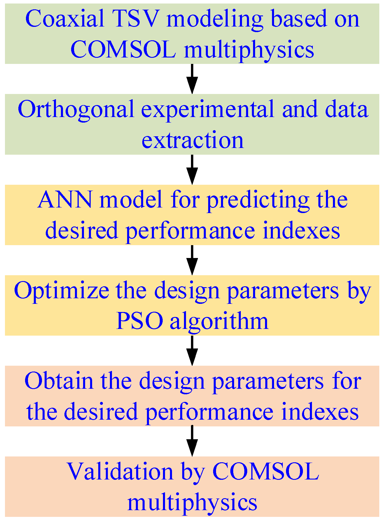
The mapping relationships between design parameters and thermal-stress performance indexes are described by ANN models to increase the efficiency of simulation design.
(2)
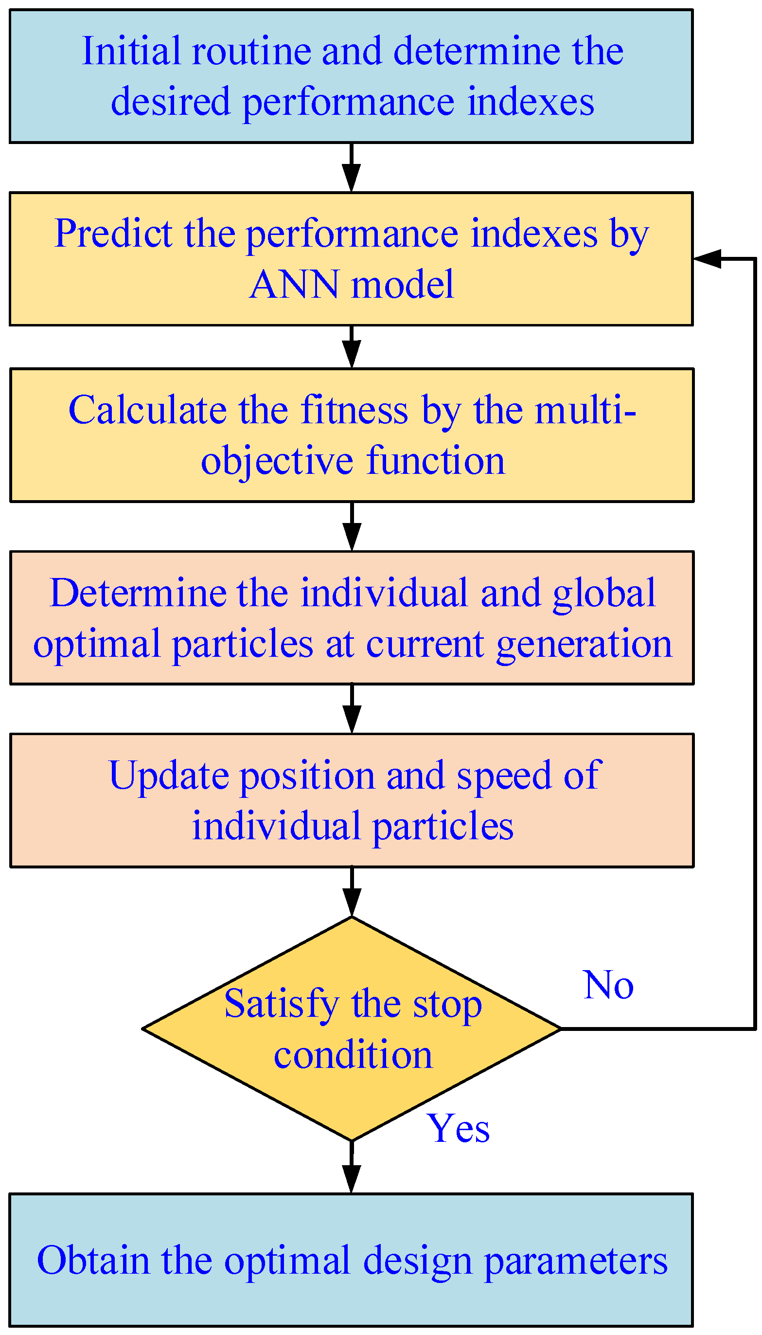
Based on the PSO algorithm, the thermal-stress coupling optimization method is proposed to control the thermal-stress distribution of coaxial TSV.
In Section 2, the FEM model of coaxial TSV is presented, then the simulation results are presented. Section 3 describes the thermal-stress coupling optimization method of coaxial TSV. In Section 4, the implementation and discussion of the proposed method are presented. Finally, Section 5 makes a conclusion.

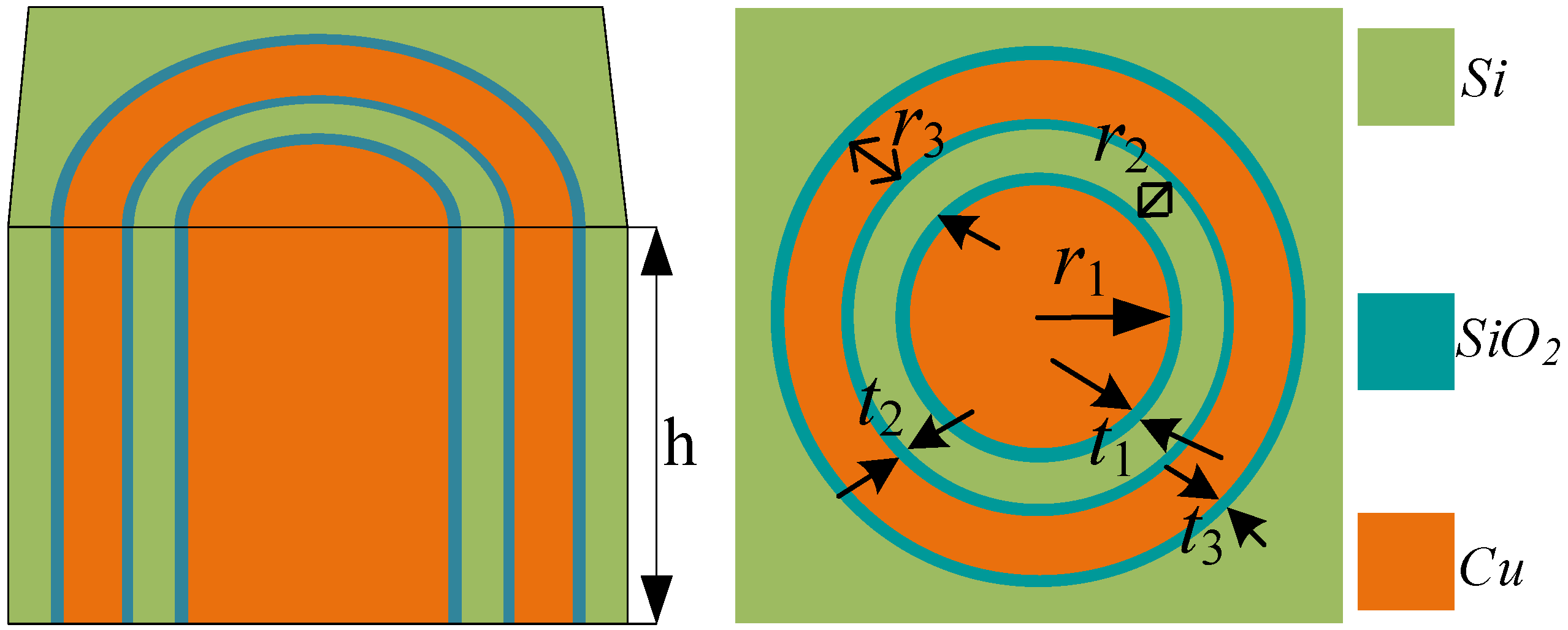
2. Finite Element Simulation of Coaxial TSV

2.1. Thermal-Stress Coupling Model

Due to the difference in the coefficient of thermal expansion, the architecture will expand or contract during temperature changes and generate thermal stress. Elastic mechanics is the foundation and branch of solid mechanics. Based on Hooke’s law, the elastic stress model can be expressed as
A σ + f = ρ μ + μ μ
ε = L μ
σ = D ε
A = x 0 0 y 0 z 0 y 0 x z 0 0 0 z 0 y x
where μ , σ and ε are displacement, stress and strain. A is the differential operator. L is equal to A T . f is the force. D is an elastic matrix, which is determined by Poisson’s ratio and Yang’s modulus of the material itself. ρ represents the density of the material.

2.2. Finite Element Model of Coaxial TSV

The schematic of coaxial TSV is shown in Figure 1, which is composed of a TSV copper column and coaxial cylinder. Obviously, the structure of coaxial TSV is symmetric. The electrical signal is transmitted by a copper column, and the coaxial cylinder is a shield layer. The signal and shield layers are filled with different materials. In addition, the height of the coaxial TSV is 50 μm. r1 is the radius of the copper column. r2 is the thickness of the dielectronic layer. r3 is the thickness of the coaxial cylinder. t1 is the thickness between the copper column and the dielectronic layer. t2 is the thickness between the dielectronic layer and the coaxial cylinder. t3 is the thickness between the coaxial cylinder and the substrate. The finite element simulation software is COMSOL Multiphysics, which can accurately present the thermal-stress distribution of coaxial TSV. The materials and parameters used in the FEM simulation are shown in Table 1, which shows the ideal material properties of Cu, SiO2 and Si. These material properties are idealized. Due to the good conductivity and compatibility with CMOS processes of Cu material, coaxial TSV conductive filling is currently generally achieved by copper plating. The goal of electroplating is low stress, with no holes and voids during the manufacturing of coaxial TSV. In the manufacturing of coaxial TSV, the critical material property deviation can make experiments deviate from the simulation and optimization [29,30,31]. Therefore, the material property deviation between actual and ideal conditions should be minimized.

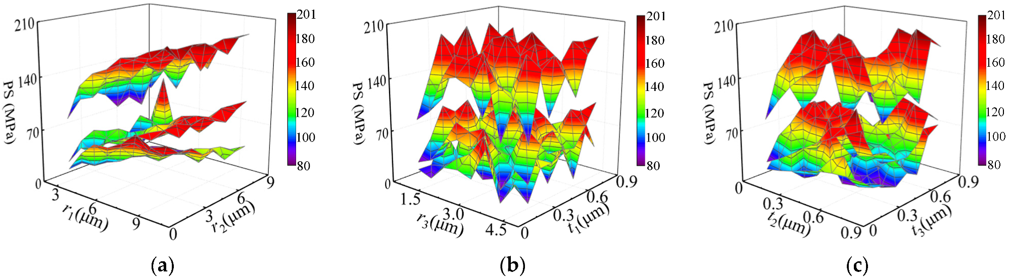
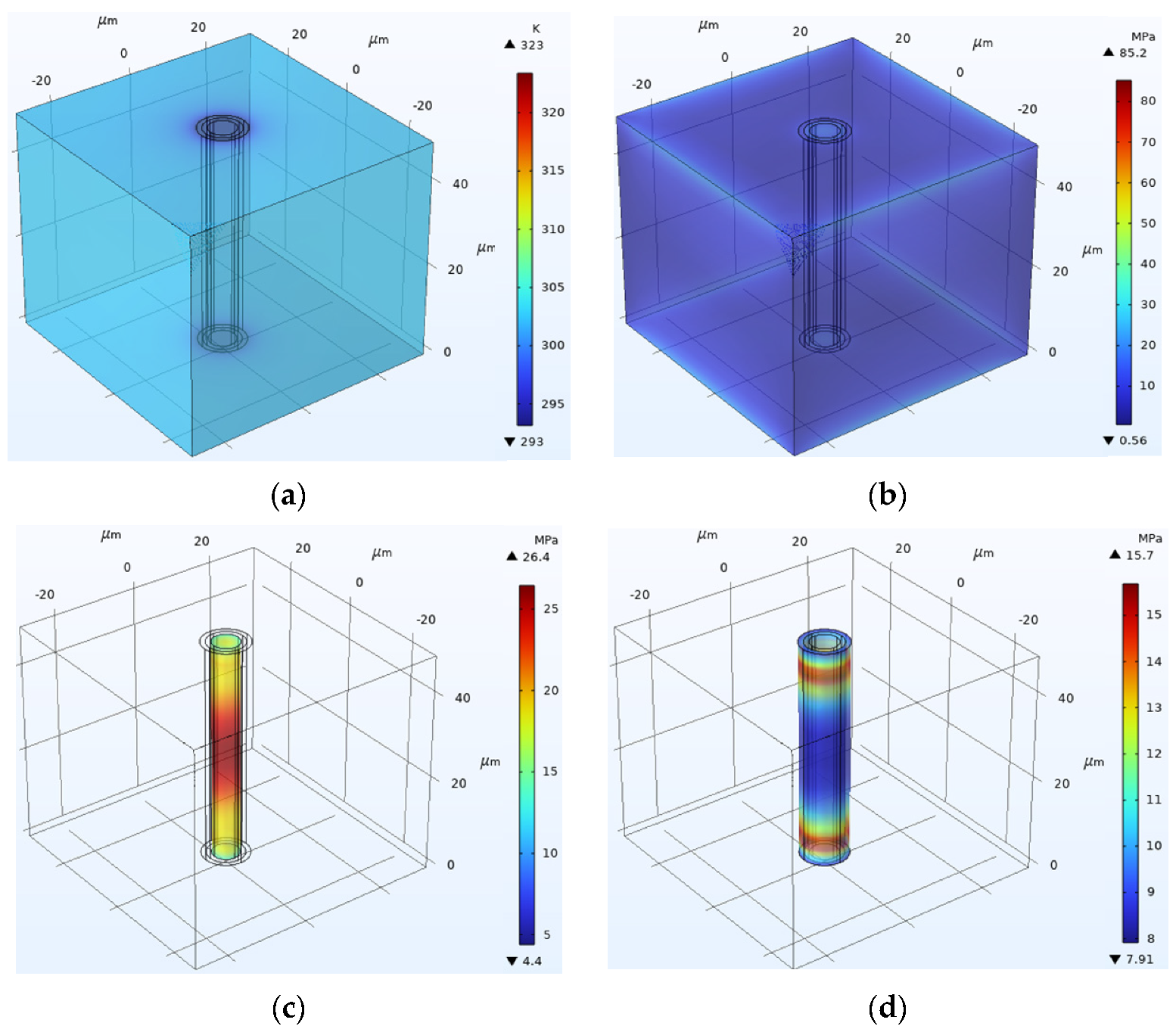
2.3. Simulation Results

In this study, the design parameters of coaxial TSV include r1, r2, r3, t1, t2 and t3. Basically, the performance indexes are affected by the design parameters of coaxial TSV. The orthogonal experiment was conducted to reduce the number of experiments. The ranges of r1, r2 and r3 are [3, 10], [1, 8] and [1, 4.5] μm, respectively. The ranges of t1, t2 and t3 are [0.1, 0.8] μm. The performance indexes are the peak temperature (PT) and peak stress (PS1) of the whole model, the peak stress of the copper column (PS2) and the peak stress of the coaxial cylinder (PS3). The current density of the copper column is set to 8 × 10¹⁰ A/m2. Based on different design parameters, the thermal-stress coupling simulation results can be obtained, as shown in Figure 2 and Figure 3. The ranges of PT, PS1, PS2 and PS3 are [321.48, 364.89] K, [80.559, 200.84], [24.825, 111.38] and [4.2823, 89.42] MPa, respectively. Based on current research, it can be seen that the design parameters of coaxial TSV have a large impact on its performance indexes. With the increase of r3, the peak temperature is firstly increased and then decreased. Based on different design parameters, the differences between the maximum and minimum values of PT, PS1, PS2 and PS3 are 43.41 K, 120.281, 86.555 and 85.1357 MPa, respectively. Therefore, the performance indexes are affected by the design parameters. The PT, PS1, PS2 and PS3 are varied with the design parameters, and the relationship between design parameters and performance indexes is irregular and complex, which indicates that high-reliability coaxial TSV is hard to design. Therefore, it is necessary to optimize the design parameters for thermal-stress coupling coaxial TSV to improve its reliability.

3. Thermal-Stress Coupling Optimization of Coaxial TSV

In this study, a thermal-stress coupling optimization for coaxial TSV was developed based on the ANN model and PSO algorithm. The flowchart of the proposed method for coaxial TSV is shown in Figure 4. Based on the orthogonal design, the thermal-stress coupling simulation data were obtained by FEM. Then, the mapping relationships between design parameters and performance indexes were described by ANN models. Then, the design parameters were optimized by the modified PSO algorithm. Finally, the optimal design parameters of coaxial TSV were obtained by the proposed strategy. The details of the developed strategy are described as follows.

3.1. ANN Models for Performance Indexes

In this study, the mapping relationships between the design parameters and the performance indexes are described by ANN models. The architecture of the ANN model is shown in Figure 5, which is composed of an input layer, hidden layer and output layer. The inputs are the coaxial TSV design parameters (r1, r2, r3, t1, t2 and t3). The outputs are the performance indexes (PT, PS1, PS2 and PS3). According to the manual experience, the number of neurons in the hidden layer is 13. The equations of the ANN model for performance indexes can be calculated by
h 1 ( k ) = W 1 ( k ) [ r 1 f ( k ) ; r 2 f ( k ) ; r 3 f ( k ) ; t 1 f ( k ) ; t 2 f ( k ) ; t 3 f ( k ) ]
h 2 ( k ) = 1 e h 1 ( k ) 1 + e h 1 ( k )
PT f ( k ) / PS 1 f ( k ) / PS 2 f ( k ) / PS 3 f ( k ) = W 2 ( k ) h 2 ( k )
where W1 and W2 represent the weight matrices. h1 and h2 are the input and output of the hidden layer. The ANN model is trained by a back propagation neural network algorithm, and the weights update formula can be expressed as
W 1 ( k ) = W 1 ( k ) + η h 2 ( k ) [ 1 h 2 ( k ) ] h 1 ( k ) k = 1 m W 2 ( k ) e k
W 2 ( k ) = W 2 ( k ) + η h 2 ( k ) e k
where η represents the learning velocity of the ANN model. m is the number of nodes of the output layer. e is the error between the desired output and the predicted output.
In addition, the weight-updating formula of the hidden output can be expressed as
Δ Wp 2 i = η E Wp 2 i = η E y m ( k + 1 ) y m ( k + 1 ) np 2 np 2 Wp 2 i
where
E y m ( k + 1 ) = - [ y ( k + 1 ) - y m ( k + 1 ) ] ,   y m ( k + 1 ) np 2 = y m ( k + 1 ) × ( 1 y m ( k + 1 ) ) , np 2 Wp 2 i = hp 1 i
y ( k + 1 ) is the practical output of the thermal-stress coupling system. y m ( k + 1 ) is the output of the ANN model. Thus, the weight-updating formula Δ Wp 2 i can be expressed by
Δ Wp 2 i = η × [ y ( k + 1 ) y m ( k + 1 ) ] × y m ( k + 1 ) × ( 1 y m ( k + 1 ) ) × hp 1 i
Similarly, the bias-term-updating formula of the hidden-output layer can be expressed as
Δ bp 2 = η E bp 2 = η E y m ( k + 1 ) y m ( k + 1 ) bp 2 np 2 bp 2
where np 2 bp 2 = 1 . Therefore, Δ bp 2 can be computed as
Δ bp 2 = η × [ y ( k + 1 ) y m ( k + 1 ) ] × y m ( k + 1 ) × ( 1 y m ( k + 1 ) )
The weight-updating formula of the input-hidden layer can be expressed as
Δ Wp 1 i j = η E Wp 1 i j = η E y m ( k + 1 ) y m ( k + 1 ) np 2 np 2 hp 1 i hp 1 i np 1 i np 1 i Wp 1 i j
where np 2 hp 1 i = Wp 2 i , hp 1 i np 1 i = hp 1 i × ( 1 hp 1 i ) , np 1 i Wp 1 i j = U j . Thus, Δ Wp 1 i j can be expressed by
Δ Wp 1 i j = η × [ y ( k + 1 ) y m ( k + 1 ) ] × y m ( k + 1 ) × ( 1 y m ( k + 1 ) ) × Wp 2 i × hp 1 i × ( 1 hp 1 i ) × U j
Similarly, the bias-term-updating formula of the input-hidden layer can be expressed as
Δ Wp 1 i j = η × [ y ( k + 1 ) y m ( k + 1 ) ] × y m ( k + 1 ) × ( 1 y m ( k + 1 ) ) × Wp 2 i × hp 1 i × ( 1 hp 1 i ) × U j
Δ bp 1 i = η E bp 1 i = η E y m ( k + 1 ) y m ( k + 1 ) np 2 np 2 hp 1 i hp 1 i np 1 i np 1 i bp 1 i
where np 1 i bp 1 i = 1 . Therefore, Δ bp 1 i can be computed as
Δ bp 1 i = η × [ y ( k + 1 ) y m ( k + 1 ) ] × y m ( k + 1 ) × ( 1 y m ( k + 1 ) ) × Wp 2 i × hp 1 i × ( 1 hp 1 i )

3.2. Multi-Objective Optimization Function

In this study, the performance indexes are the PT, PS1, PS2 and PS3. Therefore, the multi-objective optimization function can be expressed as
F = α ( P T P T des P T max P T min ) 2 + β ( P S 1 P S 1 des P S 1 max P S 1 min ) 2 + γ ( P S 2 P S 2 des P S 2 max P S 2 min ) 2 + λ ( P S 3 P S 3 des P S 3 max P S 3 min ) 2
where α , β , γ and λ represent the weight coefficients. PTdes, PS1des, PS2des and PS3des are the desired PT, PS1, PS2 and PS3, respectively. PTmax, PTmin, PS1max, PS1min, PS2max, PS2min, PS3max and PS3min represent the maximum and minimum of PT, PS1, PS2 and PS3, respectively.

3.3. Optimize Parameters by Particle Swarm Optimization Algorithm

In this study, the modified PSO algorithm was adopted to optimize the design parameters of coaxial TSV, as shown in Figure 6. The parameters of the developed strategy are presented in Table 2. The flowchart of the modified PSO algorithm can be expressed.
Step 1. The parameters of the PSO algorithm should be initialized, and the desired performance indexes should be determined.
Step 2. The performance indexes can be predicted by the established ANN model.
Step 3. The fitness can be calculated based on the established multi-objective criteria.
Step 4. The individual and global optimal particles at the current generation can be determined by comparing the fitness of particles.
Step 5. The position and speed of individual particles should be updated to
v i ( t + 1 ) = w ( i t e r ) v i ( t ) + c 1 r 1 ( p i x i ( t ) ) + c 2 r 2 ( p g x i ( t ) )
x i ( t + 1 ) = x i ( t ) + v i ( t + 1 )
w ( i t e r ) = i t e r max i t e r i t e r max ( w max w min ) + w min
where c 1 and c 2 represent the learning factor. p i and p g represent the best previous positions of the ith individual and all particles in the current generation. r 1 and r 2 are the random values uniformly distributed in the range of [0, 1]. w , w min and w max represent the inertia weight, and its lower and upper bounds, respectively. iter is the current iteration of the algorithm; i t e r max is the maximum number of iterations.
Step 6. Determine whether the stop conditions have been reached. If it is not satisfied, return to the second step. Otherwise, go to the next step.
Step 7. The optimal design parameters are obtained.
From Figure 2 and Figure 3, it can be seen that the ranges of PT, PS1, PS2 and PS3 are [321.48, 364.89] K, [80.559, 200.84], [24.825, 111.38] and [4.2823, 89.42] MPa, respectively. In order to control the thermal-stress distribution, the desired PT, PS1, PS2 and PS3 are 325 K, 85, 25 and 16 MPa. In this study, these values of desired performance indexes were determined based on data analysis and were within manageable limits.

4. Implementation and Discussion

In order to verify the effectiveness of the developed thermal-stress coupling optimization strategy for coaxial TSV, the FEM simulation experiment was conducted. In addition, the design efficiency of coaxial TSV is discussed.

4.1. Implementation

In order to verify the effectiveness of the developed thermal-stress coupling optimization of coaxial TSV, the COMSOL Multiphysics software was used to simulate the thermal-stress coupling coaxial TSV at the optimized parameters. In case A, the optimized design parameters (r1, r2, r3, t1, t2 and t3) of coaxial TSV are 3.02, 1.02, 1, 0.103, 0.103 and 0.103, respectively. The simulation results of coaxial TSV under the optimized parameters are shown in Figure 7. The PT, PS1, PS2 and PS3 of FEM simulation at the optimized parameters are 323.38 K, 85.28, 26.46 and 16.41 MPa, respectively. The PT, PS1, PS2 and PS3 of FEM simulation at the optimized parameters agree well with the desired ones (325 K, 85, 25 and 16 MPa). In order to better test the effectiveness of the developed strategy, different constraints have been imposed on the developed strategy. In case B, the optimized r1, r2, r3, t1, t2 and t3 of coaxial TSV are 3, 1, 1.46, 0.1, 0.1 and 0.1, respectively. The PT, PS1, PS2 and PS3 of FEM simulation at the optimized parameters are 321.58 K, 80.51, 24.96 and 15.6 MPa, respectively. The PT, PS1, PS2 and PS3 of FEM simulation at the optimized parameters of case B also agree well with the desired ones. Therefore, the developed strategy can efficiently optimize the design parameters of coaxial TSV to control the thermal-stress distribution.

4.2. Comparison and Discussion

In this research, the desired, optimized and simulated performance indexes of thermal-stress coupling optimization for coaxial TSV are shown in Table 3. The optimized performance indexes agree well with the desired ones. In case A, the errors of PT, PS1, PS2 and PS3 between the desired and simulated results are 0.49%, 0.33%, 5.8% and 2.56%, respectively. In case B, the errors of PT, PS1, PS2 and PS3 between the desired and simulated results are 0.49%, 0.63%, 16.8% and 3.85%, respectively. This is because the error between the ANN model and FEM existed. However, the simulated and optimized performance indexes also agree well with the desired ones, which indicates the high reliability of the developed thermal-stress coupling optimization strategy for coaxial TSV. So, the developed strategy can control the temperature and stress distributions to improve the reliability of coaxial TSV. Compared with the reported work in ref. [32], it can be seen that the peak stress is about 562 MPa when the cylindrical metal diameter is 7 μm. However, the peak stress of the developed method is 85.28 MPa. Therefore, the developed method can control thermal-stress performance indexes of coaxial TSV.
In addition, the CPU of the computer is Intel(R) Core (TM) i5-10500. The random-access memory is 8 GB. The run time of the ANN model is 0.05 s, while the run time of FEM software is 170 s. Obviously, the FEM software is time-consuming and inefficient, which can increase the development cycle and cost. However, in the developed method, the ANN model was used to replace the FEM software, which can reduce the run time. In addition, the PSO algorithm was used to optimize the design parameters, which does not require manual iteration optimization. Moreover, the optimized parameters of case A are almost at the boundary. In future research, the range of design parameters will be expanded to improve the effectiveness of the developed method. Different sets of constraints have been imposed on the developed thermal-stress coupling optimization strategy to test its effectiveness to deliver a suitable configuration. When the PT and PS1 are decreased, the FEM simulation results and optimized results are close to the desired performance indexes. However, the design parameters of coaxial TSV are almost determined at the design boundary, which indicates that the range of design parameters is limited. In future research, the range of design parameters will be expanded to investigate the high-reliability thermal-stress coupling optimization design scheme.

5. Conclusions

This paper presented a thermal-stress coupling optimization for coaxial TSV based on the ANN model and modified PSO algorithm. The developed strategy can control the thermal-stress distribution of coaxial TSV. Based on COMSOL Multiphysics software, the finite element model of coaxial TSV was established to analyze the relationship between design parameters and performance indexes. In addition, the ANN model was utilized to describe the mapping relationships between the design parameters and the performance indexes. Under the framework of the PSO algorithm, the thermal-stress coupling optimization for coaxial TSV was developed to optimize the design parameters and further improve its reliability. The performance indexes (323.38 K, 85.28, 26.46 and 16.41 MPa) of FEM simulation at the optimized parameters agree well with the desired ones (325 K, 85, 25 and 16 MPa). Therefore, the design parameters can effectively be optimized by the developed thermal-stress coupling optimization strategy to control the thermal-stress distribution of coaxial TSV.

Author Contributions

Conceptualization, X.W. and D.C.; Resources, X.W. and Y.L.; Writing—Original draft preparation, X.W. and D.C.; Data curation, D.L.; Writing-Reviewing and Editing, D.C., C.X. and D.L.; Supervision, Y.Y. All authors have read and agreed to the published version of the manuscript.

Funding

This research was funded by the Youth Talent Fund of the Joint Fund of the Ministry of Education for Equipment Pre-Research (No: 8091B032138), Wuhu and Xidian University special fund for industry-university-research cooperation (No: XWYCXY-012021008), the Cooperation Program of XDU-Chongqing IC Innovation Research Institute (No. CQIRI-2022CXY-Z01) and the Fundamental Research Funds for the Central Universities and the Innovation Fund of Xidian University.

Institutional Review Board Statement

Not applicable.

Informed Consent Statement

Not applicable.

Data Availability Statement

Not applicable.

Conflicts of Interest

The authors declare no conflict of interest.

References

  1. Burns, J.A.; Aull, B.F.; Chen, C.K.; Chen, C.L.; Keast, C.L.; Knecht, J.M.; Suntharalingam, V.; Warner, K.; Wyatt, P.W.; Yost, D.R. A wafer-scale 3-D circuit integration technology. IEEE Trans. Electron Dev. 2006, 53, 2507–2516. [Google Scholar] [CrossRef]
  2. Wang, X.; Yang, Y.; Chen, D.; Li, D. A High-Efficiency Design Method of TSV Array for Thermal Management of 3D Integrated System. Available online: https://ieeexplore.ieee.org/document/9915793 (accessed on 11 October 2022).
  3. Knickerbocker, J.U.; Patel, C.S.; Andry, P.S.; Tsang, C.K.; Buchwalter, L.P.; Sprogis, E.J.; Gan, H.; Horton, R.R.; Polastre, R.J.; Wright, S.L.; et al. 3-D Silicon Integration and Silicon Packaging Technology Using Silicon Through-Vias. IEEE J. Solid-State Circ. 2006, 41, 1718–1725. [Google Scholar] [CrossRef]
  4. Shulaker, M.M.; Hills, G.; Park, R.S.; Howe, R.T.; Saraswat, K.; Wong, H.S.; Mitra, S. Three-dimensional integration of nanotechnologies for computing and data storage on a single chip. Nature 2017, 547, 74–78. [Google Scholar] [CrossRef]
  5. Xu, Z.; Lu, J.Q. Three-Dimensional Coaxial Through-Silicon-Via (TSV) Design. IEEE Electr. Device Lett. 2012, 33, 1441–1443. [Google Scholar] [CrossRef]
  6. Qian, L.; Qian, K.; He, X.; Chu, Z.; Ye, Y.; Shi, G.; Xia, Y. Through-Silicon Via-Based Capacitor and Its Application in LDO Regulator Design. IEEE Trans. VLSI Syst. 2019, 27, 1947–1951. [Google Scholar] [CrossRef]
  7. Qu, C.; Ding, R.; Liu, X.; Zhu, Z. Modeling and Optimization of Multiground TSVs for Signals Shield in 3-D ICs. IEEE Trans. Electromagn. Compat. 2017, 59, 461–467. [Google Scholar] [CrossRef]
  8. Yin, X.; Zhu, Z.; Yang, Y.; Ding, R. Thermo-Mechanical Characterization of Single-Walled Carbon Nanotube (SWCNT)-Based Through-Silicon via (TSV) in (100) Silicon. Nanosci. Nanotechnol. Lett. 2015, 7, 481–485. [Google Scholar] [CrossRef]
  9. Dong, G.; Shi, T.; Zhao, Y.B.; Yang, Y.T. An analytical model of thermal mechanical stress induced by through silicon via. Chin. Phys. B 2015, 24, 056601. [Google Scholar] [CrossRef]
  10. Zhao, W.S.; Wang, X.P.; Xu, X.L.; Yin, W.Y. Electrothermal modeling of coaxial through silicon via (TSV) for three-dimensional ICs. In Proceedings of the 2010 IEEE Electrical Design of Advanced Package & Systems Symposium, Singapore, 7–9 December 2010; pp. 1–4. [Google Scholar]
  11. Zhao, W.S.; Yin, W.Y.; Wang, X.P.; Xu, X.L. Frequency- and Temperature-Dependent Modeling of Coaxial Through-Silicon Vias for 3-D ICs. IEEE Trans. Electron Dev. 2011, 58, 3358–3368. [Google Scholar] [CrossRef]
  12. Qian, L.; Xia, Y.; He, X.; Qian, K.; Wang, J. Electrical Modeling and Characterization of Silicon-Core Coaxial Through-Silicon Vias in 3-D Integration. IEEE Trans. Compon. Packag. Manuf. Technol. 2018, 8, 1336–1343. [Google Scholar] [CrossRef]
  13. Dixit, P.; Yaofeng, S.; Miao, J.; Pang, J.H.; Chatterjee, R.; Tummala, R.R. Numerical and Experimental Investigation of Thermomechanical Deformation in High-Aspect-Ratio Electroplated Through-Silicon Vias. J. Electrochem. Soc. 2008, 155, H981. [Google Scholar] [CrossRef]
  14. Tsai, H.Y.; Kuo, C.W. Thermal Stress and Failure Location Analysis for Through Silicon via in 3D Integration. J. Mech. 2016, 32, 47–53. [Google Scholar] [CrossRef]
  15. Chen, D.D.; Lin, Y.C.; Wu, F. A design framework for optimizing forming processing parameters based on matrix cellular automaton and neural network-based model predictive control methods. Appl. Math. Model. 2019, 76, 918–937. [Google Scholar] [CrossRef]
  16. Lin, Y.C.; Chen, D.D.; Chen, M.S.; Chen, X.M.; Li, J. A precise BP neural network-based online model predictive control strategy for die forging hydraulic press machine. Neural Comput. Appl. 2018, 9, 585–596. [Google Scholar] [CrossRef]
  17. Garud, K.S.; Seo, J.H.; Cho, C.P.; Lee, M.Y. Artificial Neural Network and Adaptive Neuro-Fuzzy Interface System Modelling to Predict Thermal Performances of Thermoelectric Generator for Waste Heat Recovery. Symmetry 2020, 12, 259. [Google Scholar] [CrossRef] [Green Version]
  18. Abuzneid, M.A.; Mahmood, A. Enhanced Human Face Recognition Using LBPH Descriptor, Multi-KNN, and Back-Propagation Neural Network. IEEE Access 2018, 6, 20641–20651. [Google Scholar] [CrossRef]
  19. Wei, J. Application of Hybrid Back Propagation Neural Network in Image Compression. In Proceedings of the 2015 8th International Conference on Intelligent Computation Technology and Automation (ICICTA) 2015, Nanchang, China, 14–15 June 2015; pp. 209–212. [Google Scholar]
  20. Bogiatzis, A.; Papadopoulos, B. Papadopoulos. Global Image Thresholding Adaptive Neuro-Fuzzy Inference System Trained with Fuzzy Inclusion and Entropy Measures. Symmetry 2019, 11, 286. [Google Scholar] [CrossRef] [Green Version]
  21. Xu, L.; Zhang, Z.; Yao, Y.; Yu, Z. Improved Particle Swarm Optimization-Based BP Neural Networks for Aero-Optical Imaging Deviation Prediction. IEEE Access 2022, 10, 26769–26777. [Google Scholar] [CrossRef]
  22. Lu, Y.; Yan, D.; Zhang, J.; Levy, D. Direct back propagation neural dynamic programming-based particle swarm optimization. Connect. Sci. 2014, 26, 367–368. [Google Scholar] [CrossRef]
  23. Ullah, I.; Fayaz, M.; Kim, D. Improving Accuracy of the Kalman Filter Algorithm in Dynamic Conditions Using ANN-Based Learning Module. Symmetry 2019, 11, 94. [Google Scholar] [CrossRef]
  24. Chen, D.D.; Lin, Y.C. A particle swarm optimization-based multi-level processing parameters optimization method for controlling microstructures of an aged superalloy during isothermal forging. Met. Mater. Int. 2019, 25, 1246–1257. [Google Scholar] [CrossRef]
  25. Chen, D.D.; Lin, Y.C.; Chen, X.M. A strategy to control microstructures of a Ni-based superalloy during hot forging based on particle swarm optimization algorithm. Adv. Manuf. 2019, 7, 238–247. [Google Scholar] [CrossRef]
  26. Chen, D.; Zhao, J.; Fei, C.; Li, D.; Zhu, Y.; Li, Z.; Guo, R.; Lou, L.; Feng, W.; Yang, Y. Particle swarm optimization algorithm-based design method for ultrasonic transducers. Micromachines 2020, 11, 715. [Google Scholar] [CrossRef] [PubMed]
  27. Li, D.; Wang, X.; Chen, D.; Zhang, Q.; Yang, Y. A precise ultra-wideband ranging method using pre-corrected strategy and particle swarm optimization algorithm. Measurement 2022, 194, 110966. [Google Scholar] [CrossRef]
  28. Yang, Y.; Wang, X.; Li, D.; Chen, D.; Zhang, Q. An Improved Indoor 3-D Ultrawideband Positioning Method by Particle Swarm Optimization Algorithm. IEEE Trans. Instrum. Meas. 2022, 71, 1–11. [Google Scholar] [CrossRef]
  29. Fritz, T.; Mokwa, W.; Schnakenberg, U. Material characterisation of electroplated nickel structures for microsystem technology. Electrochim. Acta 2001, 47, 55–60. [Google Scholar] [CrossRef]
  30. Read, D.T.; Cheng, Y.W.; Geiss, R. Morphology, microstructure, and mechanical properties of a copper electrodeposit. Microelectron. Eng. 2004, 75, 63–70. [Google Scholar] [CrossRef]
  31. Al Farisi, M.S.; Tsukamoto, T.; Tanaka, S. Tailoring material properties of electrochemically deposited Al film from chloroaluminate ionic liquid for microsystem technology using pulsed deposition. Sens. Actuators A Phys. 2020, 316, 112384. [Google Scholar] [CrossRef]
  32. Wang, F.; Zhu, Z.; Yang, Y.; Liu, X.; Ding, R. Thermo-mechanical performance of Cu and SiO2 filled coaxial through-silicon-via (TSV). IEICE Electron. Express 2013, 10, 20130894. [Google Scholar] [CrossRef]
Figure 1. Schematic of coaxial TSV: 3D view and the cross-sectional view of coaxial TSV configuration.
Symmetry 15 00264 g001
Figure 2. Peak temperature of coaxial TSV with different design parameters: (a) r1 and r2; (b) r3 and t1; (c) t2 and t3.
Symmetry 15 00264 g002
Figure 3. Peak stress of coaxial TSV with different design parameters: (a) r1 and r2; (b) r3 and t1; (c) t2 and t3.
Symmetry 15 00264 g003
Figure 4. Flowchart of the developed thermal-stress coupling optimization for coaxial TSV.
Symmetry 15 00264 g004
Figure 5. Architecture of the artificial neural network model.
Symmetry 15 00264 g005
Figure 6. Flowchart of the modified particle swarm optimization algorithm.
Symmetry 15 00264 g006
Figure 7. Simulation results of coaxial TSV: (a) PT; (b) PS1; (c) PS2; (d) PS3.
Symmetry 15 00264 g007
Table 1. Materials and parameters used in the FEM simulation.
MaterialsCuSiO2Si
Thermal conductivity (W/(m*K))4011.4130
Thermal expansivity (ppm/K)170.52.3
Young modulus (GPa)11071130
Poisson ratio0.350.160.28
Table 2. Parameters of the developed thermal-stress coupling optimization for coaxial TSV.
Parameters of the multi-objective optimization functionDesired performance indexes P T des = 325 , P S 1 des = 85 , P S 2 des = 25 , P S 3 des = 16
Weight coefficients α = 0 . 2 , β = 0 . 3 , γ = 0 . 3 , λ = 0 . 2
Parameters of PSO algorithmConstant parameters c 1 = c 2 = 2
Maximum generation M G = 100
Population size N = 50
Range of inertia weight w [ 0.4 , 0.9 ]
Range of particle position x r 1 [ 3 , 10 ] , x r 2 [ 1 , 8 ] , x r 1 [ 1 , 4.5 ] , x t 1 , t 2 , t 3 [ 0.1 , 0.8 ]
Range of particle velocity v r 1 , r 2 , r 3 [ 1 , 1 ] , v t 1 , t 2 , t 3 [ 0.1 , 0.1 ]
Table 3. Performance indexes of desired, optimized and simulated.
IndexesCase
AB
DesiredPT (K)325320
PS1 (MPa)8580
PS2 (MPa)2530
PS3 (MPa)1615
OptimizedPT (K)323.42321.94
PS1 (MPa)85.7181.08
PS2 (MPa)26.6129.74
PS3 (MPa)16.3319.47
SimulatedPT (K)323.38321.58
PS1 (MPa)85.2880.51
PS2 (MPa)26.4624.96
PS3 (MPa)16.4115.6
Disclaimer/Publisher’s Note: The statements, opinions and data contained in all publications are solely those of the individual author(s) and contributor(s) and not of MDPI and/or the editor(s). MDPI and/or the editor(s) disclaim responsibility for any injury to people or property resulting from any ideas, methods, instructions or products referred to in the content.

