Article

Application of a Novel Synergetic Control for Optimal Power Extraction of a Small-Scale Wind Generation System with Variable Loads and Wind Speeds

by
Hamza Boudjemai
1,
Sid Ahmed El Mehdi Ardjoun
1,
Houcine Chafouk
2,
Mouloud Denai
3,
Z. M. Salem Elbarbary
4,5,*,
Ahmed I. Omar
6 and
Mohamed Metwally Mahmoud
7,*
1
IRECOM Laboratory, Faculty of Electrical Engineering, Djillali Liabes University, Sidi Bel-Abbes 22000, Algeria
2
IRSEEM, ESIGELEC, UNIROUEN, Normandie University, 76000 Rouen, France
3
School of Physics, Engineering and Computer Science, University of Hertfordshire, Hatfield AL10 9AB, UK
4
Electrical Engineering Department, College of Engineering, King Khalid University, Abha 61421, Saudi Arabia
5
Electric Engineering Department, Faculty of Engineering, Kafrelsheikh University, Kafrelsheikh 33516, Egypt
6
Electrical Power and Machines Engineering Department, The Higher Institute of Engineering at El-Shorouk City, El-Shorouk Academy, Cairo 11837, Egypt
7
Electrical Engineering Department, Faculty of Energy Engineering, Aswan University, Aswan 81528, Egypt
*
Authors to whom correspondence should be addressed.
Symmetry 2023, 15(2), 369; https://doi.org/10.3390/sym15020369
Submission received: 15 January 2023 / Revised: 21 January 2023 / Accepted: 27 January 2023 / Published: 30 January 2023
(This article belongs to the Section Engineering and Materials)

Abstract

:
The synergetic control technique (SCT) has the solution for understanding the symmetry inherent in the non-linear properties of wind turbines (WTs); therefore, they achieve excellent performance and enhance the operation of the WT. Small-scale WTs are efficient and cost-effective; they are usually installed close to where the generated electricity is used. This technology is gaining popularity worldwide for off-grid electricity generation, such as in rural homes, farms, small factories, and commercial properties. To enhance the efficiency of the WT, it is vital to operate the WT at its maximum power. This work proposes an efficient and fast maximum power point tracking (MPPT) technique based on the SCT to eradicate the drawbacks of the conventional methods and enhance the operation of the WT at the MPP regardless of wind speed and load changes. The SCT has advantages, such as robustness, simplified design, fast response, no requirement for knowledge of WT characteristics, no need for wind sensors or intricate power electronics, and straightforward implementation. Furthermore, it improves speed convergence with minimal steady-state oscillations at the MPP. The investigated configuration involves a wind-driven permanent magnet synchronous generator (PMSG), uncontrolled rectifier, boost converter, and variable load. The two converters are used to integrate the PMSG with the load. Three scenarios (step changes in wind speed, stochastic changes in wind speed, and variable electrical load) are studied to assess the SCT. The results prove a high performance of the suggested MPPT control method for a fast convergence speed, boosted WT efficacy, low oscillation levels, and applicability under a variety of environmental situations. This work used the MATLAB/Simulink program and was then implemented on a dSPACE 1104 control board to assess the efficacy of the SCT. Furthermore, experimental validation on a 1 kW Darrieus-type WT driving a PMSG was performed.

1. Introduction

The small wind turbine (WT) market is expected to experience promising growth during the next decade due to the increasing demand for low-power wind generation in isolated areas, such as rural homes, farms, and small businesses. For urban use, small vertical axis WTs (VAWTs) are the most suitable [1,2,3,4]. They are relatively quiet compared to horizontal axis WTs (HAWTs) and can operate independently of the wind direction and even capture weak winds. The development of the small-scale WT market segment has triggered an increased interest within the research/work community to augment the dynamic performance and maximize the efficiency of this technology [5,6,7]. The motivation of this work is mainly to improve the energy efficacy and production of small WTs.
Enhancing energy efficiency is mainly concerned with the operation of WTs at an optimal rotational speed to obtain the maximal allowable power [8,9,10]. However, this desired machine speed varies based on different operating scenarios (wind speed changes/electrical load). Maximal power point tracking (MPPT) techniques are employed for maintaining the machine’s speed at the optimum operating point. MPPT methods are implemented in different ways depending on whether the WT is fortified with an anemometer and whether the power curves’ (PC) characteristics are known.
Among the MPPT techniques that require knowledge of the WT’s PC characteristics and the use of an anemometer, we can mention the techniques based on optimal torque control (OTC) [11,12,13], tip speed ratio (TSR) [14,15], and power signal feedback (PSF) control [16]. These MPPT strategies are characterized by their speed of response and robustness. However, there are some difficulties that make the implementation of these techniques complex: (i) selecting the location of the anemometer; and (ii) the non-linearity of the WTs PC characteristic, the difficulty in obtaining these curves, and their uncertainties following the aging of the WT [17,18]. This has prompted many researchers to develop other more efficient MPPT techniques, such as the perturb & observe (P&O), that do not require data on the WT characteristics or the use of an anemometer. The P&O consists of applying a small disturbance around the initial value of the controlled variable (rotation speed, voltage, current, duty cycle, etc.) and then observing its effect at the level of the power signal at the machine’s output in order to define the direction to follow to reach the optimal operating point. The P&O control principle is simple but has some drawbacks, such as bad convergence towards the optimal power point during a sudden change in the wind speed and degradation in the power dynamic response because of the difficulty to select the appropriate step size for the algorithm (large steps can cause oscillations in the power and a long response time) [19]. To improve this technique, the authors in [20] proposed a new P&O technique built on the knowledge of the WT’s inertia stored energy. This method has good performance for following the MPP, thus eliminating the problems of slow response and misdirection that exist in the conventional P&O. However, its shortcoming is that it requires knowledge of the WT’s inertia. In [21], the authors suggested a new P&O method that uses the output voltage and current of the rectifier (AC/DC) stage to regulate the boost converter’s duty cycle (D) without any a priori knowledge about the incoming wind speed or the parameters of the WT. Hence, the D’s step size is automatically adjusted to achieve fast and accurate convergence to the optimum power point. The authors in [22] proposed a method based on a linear connection between the optimal machine speed and the measured wind speed. In addition, a large-step forward and small-step back initial following strategy has also been proposed to progress the accuracy of the classic large-step P&O technique and to ensure a better MPPT under rapidly varying received wind speeds.
The MPPT technique based on fuzzy logic does not necessitate any a priori data of the parameters of the WT system. This technique brings numerous advantages and gives a fascinating performance for MPPT, especially with fluctuated wind speeds [23,24,25,26]. However, this technique exhibits poor performance under variable load conditions, which must be taken into consideration. Numerous MPPT techniques have been implemented and investigated in the literature survey with and without knowledge of the characteristics of the WT. However, most of these works do not address the impact of electrical load variations and WT inertia.
This study proposes a novel MPPT technique based on synergetic control, which presents the solution for understanding the symmetry inherent in the non-linear properties of wind turbines (WTs); therefore, they achieve excellent performance and enhance the operation of the WT. A MPPT technique based on the SCT is applied to force the WT to operate at the MPP even under variable wind speed and load conditions. The proposed MPPT is simple, easy to implement, and does not necessitate data on the WT’s PC characteristics and machine parameters. Therefore, an anemometer is not required, and complex power electronics are not needed; as a result, the cost is decreased, and the reliability of the system is enhanced.
The remainder of the article is structured as follows: Section 2 offers a general description of the studied small WT system. Section 3 presents the suggested MPPT technique. The simulation and experimental results are analyzed and investigated in Section 4 and Section 5, respectively. Section 6 presents the conclusions and perspectives of the proposed study.

2. Description and Modeling of the Investigated Wind System

The configuration of the low-power, variable-speed WT system used in this work is depicted in Figure 1 [27]. It is made up of a permanent magnet synchronous generator (PMSG) driven by a Darrieus-type VAWT and connected to an electrical load via two converters: an uncontrolled rectifier and a controlled boost chopper. The efficiency and feasibility of this wind energy conversion system have been used in several research works and are commonly used in hybrid renewable energy systems [6,14,17,28].
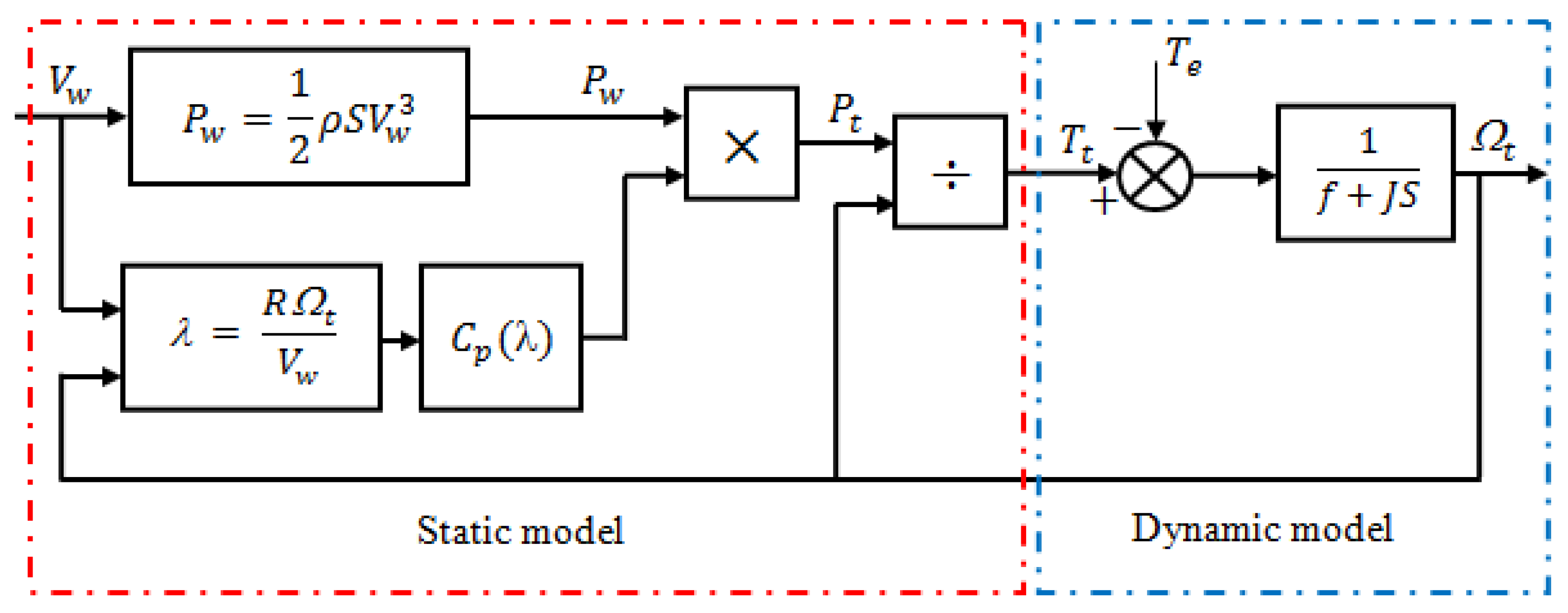
WTs alter the kinetic energy (KE) of wind into mechanical power/energy (ME). However, during this conversion process, the WT can take only a portion of the wind power. Therefore, the aerodynamic power accessible on the slow shaft of the WT is written by:
P t = 1 2 ρ S V w 3 C p ( λ )
where V w denotes the wind speed ( m / s ) ,   S is the surface area by the blades of the WT ( m 2 ) , λ represents the relative speed or speed ratio ( rad / s ) , ρ is the air density ( kg / m 3 ) ,   and   C p is the power coefficient that is specific to each WT and defines the capacity of the WT to alter the KE of the wind into ME. This coefficient is limited to a maximal value of 0.593 that is called the Betz limit, which should not be exceeded. The WT considered in this work is characterized by the next power coefficient [6].
C p ( λ ) = 0.00054 λ 4 0.01098 λ 3 + 0.057456 λ 2 0.02493 λ + 0.110898
with:
λ = R t V w
where R represents the WT’s radius ( m ) , and t is the WT’s rotational speed ( rad / s ) .
In addition, the power extracted by the WT is transmitted to the generator by a mechanical shaft, which is represented by the next differential equation:
J d m d t = T t T e f m
where f and J are the total coefficient of friction and total inertia of the WT-generator system, respectively. T t denotes the torque supplied by the WT to the PMSG ( N · m ) , T e is the electromagnetic torque of the PMSG ( N · m ) , and m represents the rotation speed of the shaft coupling the WT and the PMSG ( rad / s ) . In our case, m = t since there is no gearbox. Furthermore, the WT’s model and the mechanical shaft are depicted in Figure 2.
PMSGs are currently among the most widely used electrical machines in the design of wind systems due to their high efficiency and the absence of an excitation system [29,30,31]. These machines have many poles and, therefore, can be directly connected to the WT without the need for a gearbox, which then reduces the cost and mechanical losses in the wind chain [32,33].
The model of the PMSG can be simplified by assuming that the self-resistances and inductances are constant and by neglecting the effects of saturation in the magnetic circuit, the skin effect, Foucault currents, and the hysteresis phenomena. Furthermore, since the neutral in the machine is not included, the homopolar component will be zero. Based on these assumptions, the PMSG with a permanent magnet in the reference ( d q ) can be described with the next equations:
{ v d = R s i d L d d i d d t + m L q i q v q = R s i q L q d i q d t m ( L d i d φ f )
The PMSG mechanical equation is expressed with the next equation:
J m d m d t = T t T e f m m
The parameters T e and the output power of the PMSG are given by:
T e = 3 2 N p [ ( L d L q ) i d i q + i q φ f ]
P g = v d i d + v q i q
where J m is the PMSG’s inertia ( kg · m 2 ) ;   f m is the coefficient of friction of the generator ( N · m · s / rad ) ; v d and v q denote the stator voltages in the reference ( d q ) ;   i d and i q represent the stator currents in the reference ( d q ) ; R s denotes the resistance of the windings; L d and L q are, respectively, the self-inductances of the axes d and q ; φ f is the permanent magnets’ flux ( W b ) ;   N p is the pole pairs’ number; and P g is the electrical power delivered by the machine in the reference ( d q ) .
The rectifier’s output voltage is defined as:
V i n = 3 6 π V P M S G
with:
V P M S G = ( k e m ) 2 ( I s L s m ) 2
where V P M S G is the phase voltage of the generator, k e is the voltage constant of the generator and k e m denotes the induced voltage, I s is the stator current, and L s denotes the self-inductance of the stator winding.
From Equations (9) and (10):
V i n = 3 6 π m k e 2 ( I s L s ) 2
From Equation (11), it can be observed that the output voltage of the rectifier is directly proportional to the m . Consequently, the voltage can be used to adjust the m of the PMSG and hence the power transported by the WT. The MPPT technique proposed in Section 3 uses this principle to force the WT to harvest the maximal power.
In the design of the variable speed wind system, power converters play a very significant role in the control of the energy transfer between the generator and the load. In this paper, a boost power converter is utilized to regulate and control the energy transfer, which simplifies the control law considerably. This converter can be modeled with the following state space equations:
{ x ˙ 1 = I i n C 1 x 2 C 1 x ˙ 2 = x 1 L ( 1 D ) V o u t L
where x = [ x 1 x 2 ] T = [ v i n i L ] T represents the state vector, and D ranges are ( 0 < d < 1 ) .

3. MPPT Technique Based on Synergetic Control

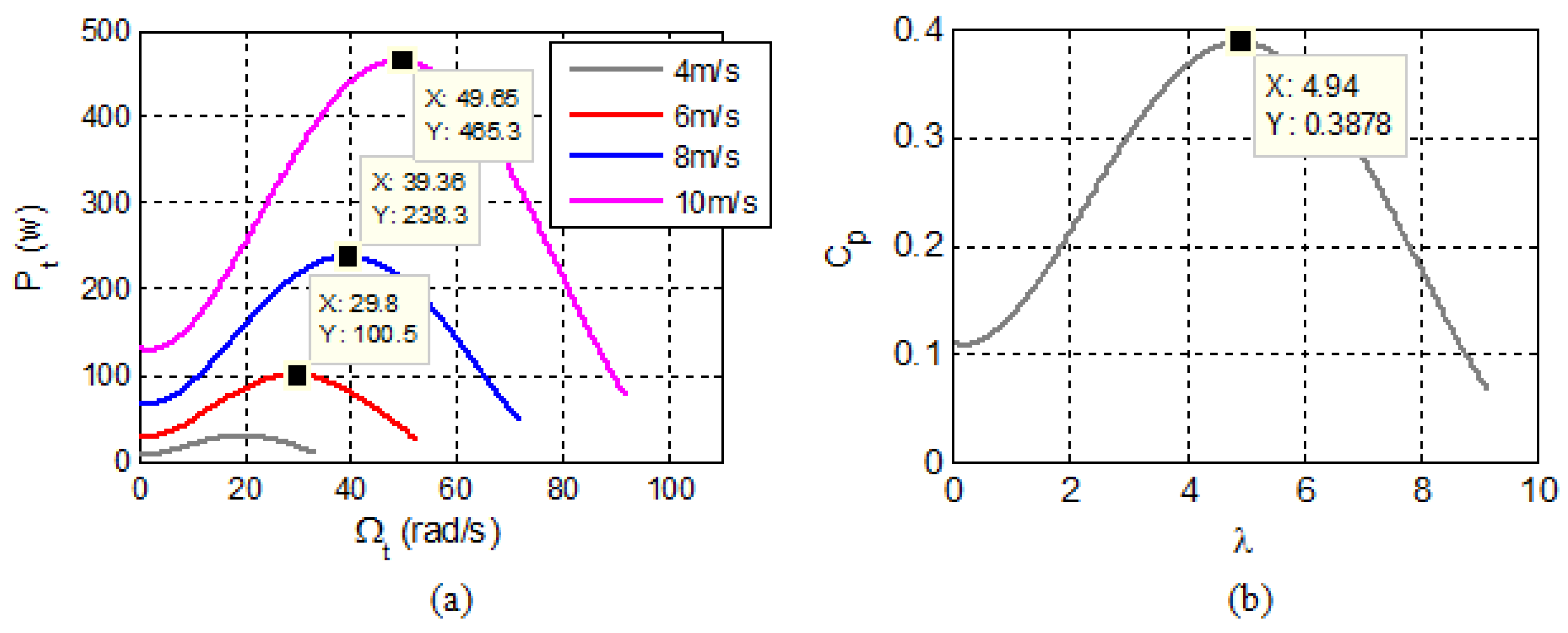
The WT’s power characteristics studied are depicted in Figure 3a. These characteristics show that the mechanical power obtained by the WT is maximum only at C p _ m a x = 0.388 ,   λ o p t = 4.94 (see Figure 3b). Thus, to run the WT at this point, regardless of the operating conditions, this work proposes a novel MPPT technique based on the synergetic control (SC) theory. The key point of our approach is that the control law is simple, does not need information on the real WT characteristics or the PMSG parameters, and does not need an anemometer.
SC is a powerful control technique for nonlinear systems for its ability to take into account the system’s nonlinearities in the control design. The SC theory has been successfully applied in several control areas [34,35,36,37]. The SC concept is similar to the sliding mode control, where the system under study is forced to evolve along a trajectory predetermined by the user (sliding surface is replaced by the macro-variable). The used algorithm is presented as follows.
Recall that a nonlinear dynamic system of order n is represented by the next differential equation:
d x ( t ) d t = f ( x , u , t )
where x is the vector of system state variables, and u represents the command signal.
The first and most important step in the design of the SC is the choice of the macro-variable, which is given by:
Ψ = h ( x , t )
The macro-variable is defined as a simple linear combination of state variables. Its main characteristics are chosen by the user according to the control objectives.
After the selection of the macro-variable, the objective of the SC is to force the states of the system to operate on the domain previously chosen by the user ( Ψ = 0 ) using the following law of convergence:
T Ψ ˙ + Ψ = 0
where
Ψ ˙ = d Ψ d t = d Ψ d x d x d t = d Ψ d x x ˙
where T is a positive constant that indicates the speed of convergence to the macro-variable.
The time-derivative of the macro-variable is given by:
d Ψ ( x , t ) d t = d Ψ ( x , t ) d x d x d t
Substituting (13) and (17) in (15) gives:
T d Ψ ( x , t ) d x f ( x , u , t ) + Ψ = 0
Solving this equation gives the control law u which is expressed as:
u = g ( x , t , Ψ , T )
The stability of the synthesized control law is ensured by using the Lyapunov theory (LT). Consider the following LT:
V = 1 2 Ψ 2
Taking the time-derivative of V gives:
d V d t = Ψ Ψ ˙ = 1 T Ψ 2
which is always negative, and hence, the system is asymptotically stable in the sense of LT.
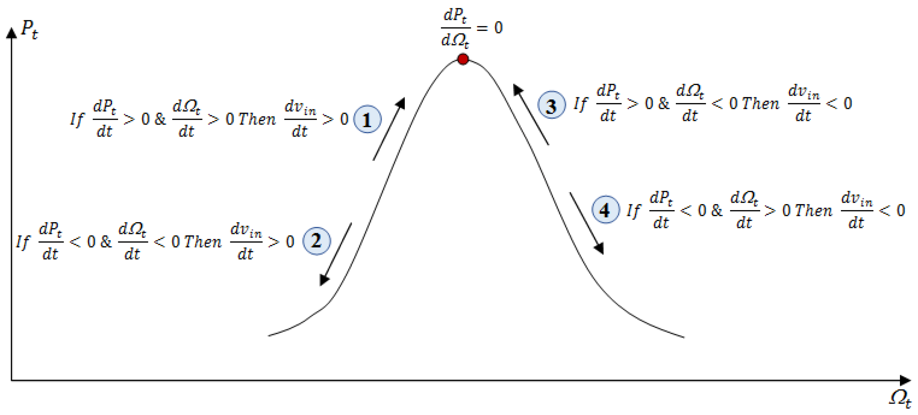
As discussed in the previous section, the variation in the voltage v i n at the input of the boost-converter can change the speed of rotation, consequently changing the power delivered by the WT. The evolution of this head voltage can be inferred from the progression of the WT power P t and the t , as illustrated in Figure 4. For example, in the first case, it is clearly noticed that the t and the power generated by the WT both increase; this means that the WT power approaches its maximum from the left side. To continue in the same direction, both the rotational speed and the voltage must be increased. The same principle applies to the other three cases.
Based on the results shown in Figure 4, it can be deduced that the derivative of the voltage d v i n d t can be chosen proportional to d P t d t .
d v i n d t = k d P t d t
where v i n is the input voltage of the boost converter, and k is a large positive constant.
The main steps for designing the new MPPT based on the SC are described below.
First, a macro-variable is defined so as to keep the WT operation in the MPP. Using Equation (22), the selected macro-variable is defined as follows:
Ψ = d v i n d t k d P t d t
The next step is to specify the control law of the converter, which guarantees the maximal power efficiency of the WT.
Substituting the first equation of system (12) in (23) gives:
Ψ = I i n C 1 x 2 C 1 k d P t d t
Since the two states x 1 and x 2 of the converter correspond to the v i n and the current i L of the inductance, then:
ψ ˙ = d Ψ d x 1 x ˙ 1 + d Ψ d x 2 x ˙ 2
and since Ψ is a function of x 2 only, Equation (25) becomes:
ψ ˙ = d Ψ d x 2 x 2 ˙ = 1 C 1 ( x 1 L ( 1 d ) V o u t L )
Substituting ψ ˙ from (26) in the law of synergetic convergence described in (13–21), we obtain:
v i n L C 1 + ( 1 d ) V o u t L C 1 = Ψ T
After simplifying Equation (27), the synergetic control law that represents the core of our MPPT technique is defined as follows:
d = 1 1 V o u t ( v i n Ψ L C 1 T )
Finally, it can be seen that the SC law remains simple, reliable, and easy to design and implement in practice. The constants T and k need to be defined for the design of the suggested MPPT technique in addition to the boost converter parameters L and C 1 . The schematic diagram of the control law obtained from the SC is depicted in Figure 5.

4. Discussion of Simulated Results

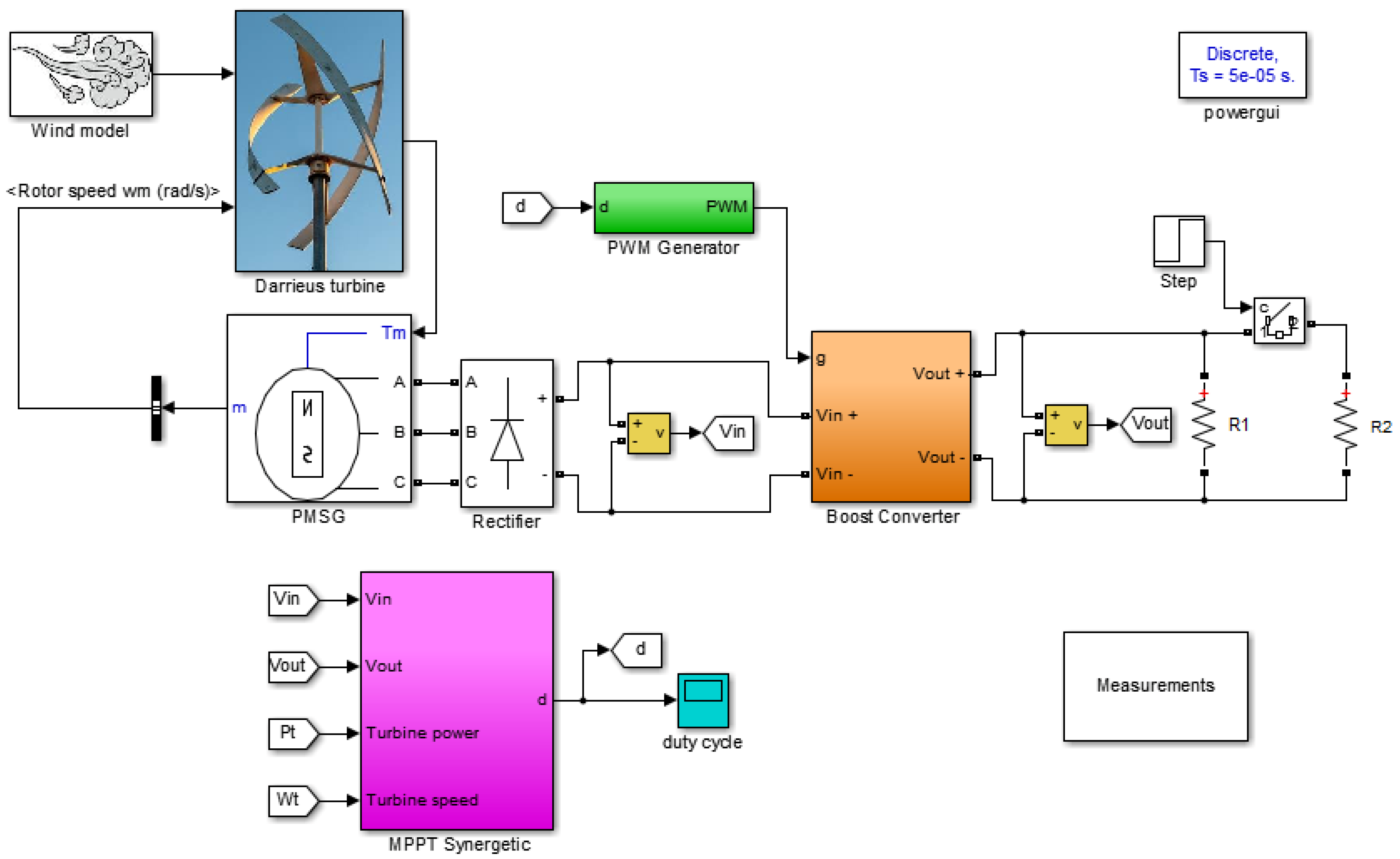
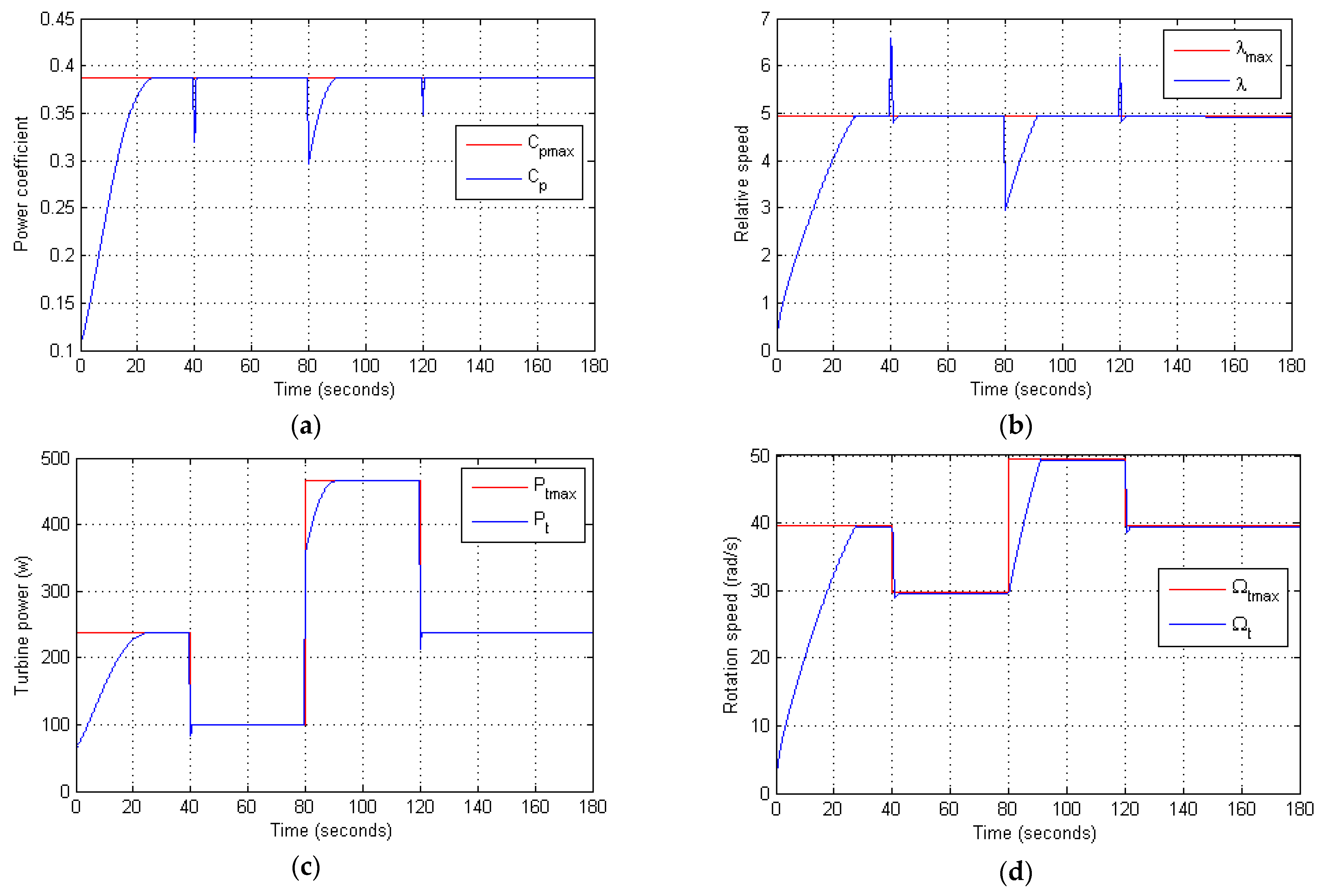
The overall model of the WT system and MPPT control scheme was developed in MATLAB/Simulink as seen in Figure 6. To assess the performance and robustness of the suggested MPPT technique, the following tests were carried out: (i) taking into consideration or not the WT’s inertia impact, (ii) applying a wind profile with four sudden jumps (Figure 7a), and (iii) variation of the load at t = 150 s. The obtained simulated results are shown in Figure 7 and Figure 8. The results obtained in this study are also compared with other researchers [6], who have used the same WT model but with other MPPT techniques.
It is realized from Figure 7 that, with the wind profile applied to the investigated WT (Figure 7a), all the responses of the power coefficient, relative speed, rotational speed, and power of the WT are fast and follow their optimal references accurately. Furthermore, all the optimal points mentioned in Figure 3 are successfully reached with the proposed MPPT technique. From Figure 7, it is observed that the suggested MPPT is very effective even under varying electrical load conditions. All the responses of the investigated system are maintained within their optimal values, except for the boost converter’s current and voltage, which are varied to maintain maximum power (Figure 7g,h).
Furthermore, the key objective of the test in which we do not take into account the inertia of the WT is only to show the rapidity of the proposed MPPT technique at following the point of maximum power. On the other hand, in the opposite case (see the results of Figure 8), the large impact of the WT inertia can be clearly observed causing a long response time of approximately 20 s for each variation of the wind speed (This was also observed in the results of reference [6]). This demonstrates the ability of the proposed MPPT technique to work perfectly well in the case of large WT inertia with a lower response time of approximately 8 s for each jump in the wind speed.
The results obtained in Figure 7 and Figure 8 demonstrate a higher performance of the investigated MPPT as compared with the reference [3] where the authors used the same WT characteristic. The suggested MPPT technique is faster and more effective than the MPPT technique based on the search for the extremum described in the article [6].

5. Discussion of Experimental Results

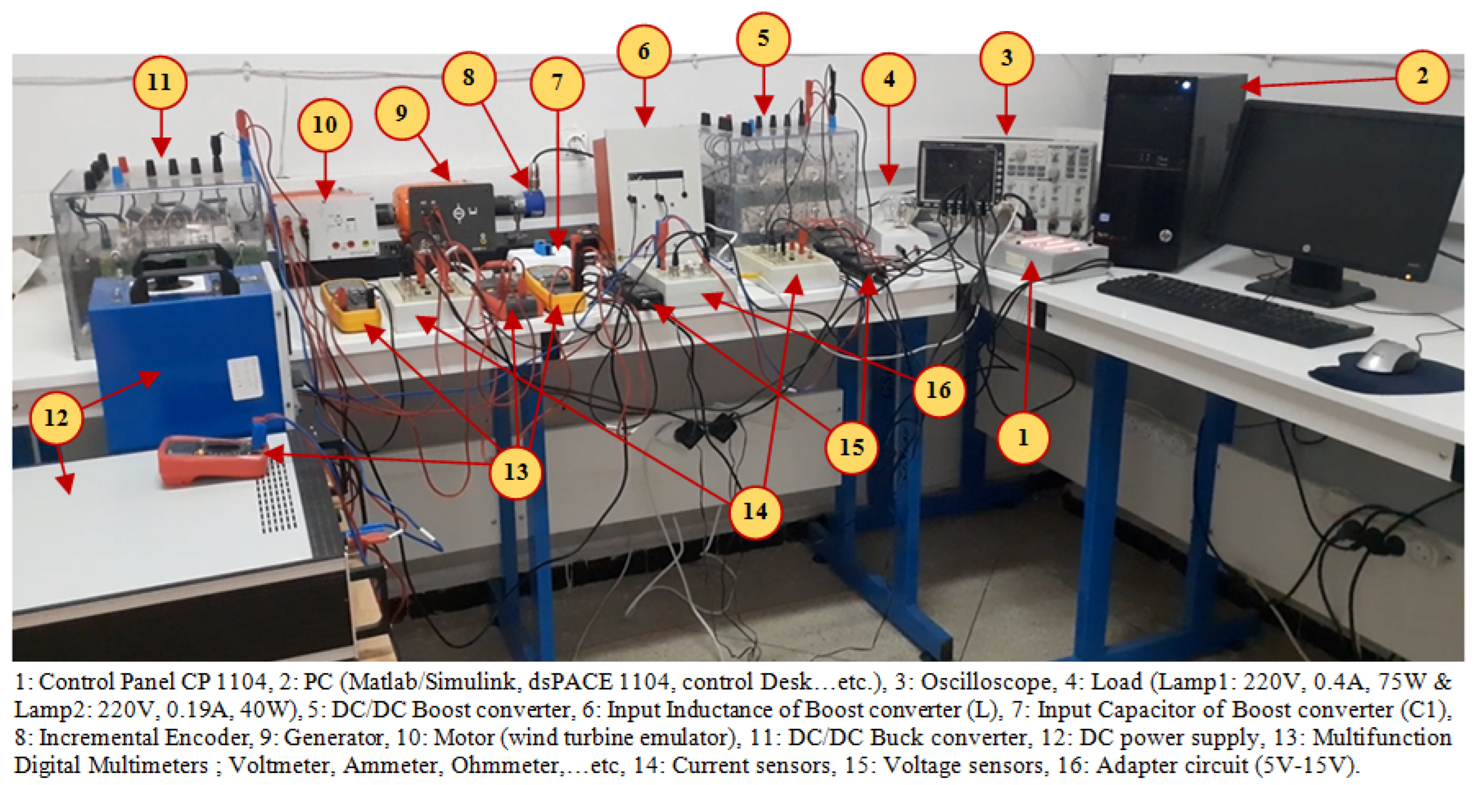
To assess the performance of the suggested MPPT technique under real-time conditions, an experimental setup was designed as seen in Figure 9. The system parameters are listed in Table 1 [38]. The setup consisted of a WT emulator, which can accurately reproduce the mechanical behavior of a real WT. A detailed description of this emulator is found in [38,39]. The controls and the MPPT were instigated on a dSPACE 1104 card and programmed using MATLAB/Simulink, as depicted in Figure 10, to validate the proposed control strategy. A low-pass filter with a cut-off frequency ( ω c = 100   rad / s ) was used to smooth the measured signals from the current sensors to be used in the MPPT. Several tests with variable wind and variable electrical load were carried out during this study. The effect of the WT’s inertia was considered. The series of conducted scenarios and their results are summarized below:

5.1. Consecutive Changes in Wind Speed with a Constant Electrical Load

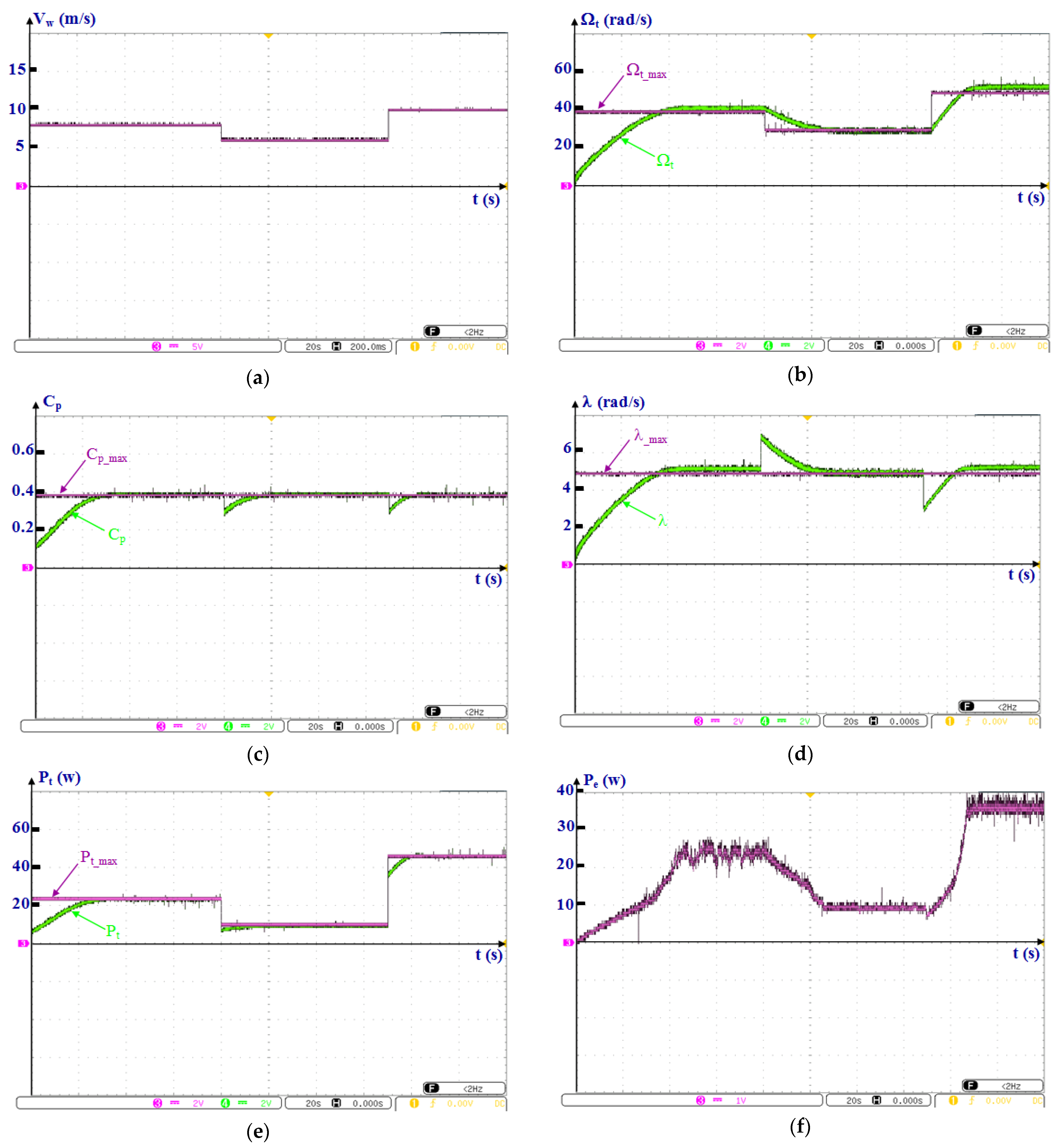
This scenario was aimed to assess the robustness and response time of the proposed MPPT technique to find all the optimal points mentioned in Figure 3. For this purpose, a variable wind speed profile included three-step changes in the range between 6 m/s and 10 m/s, as depicted in Figure 11a. The electrical power produced was transmitted to a fixed electrical load of 75 W. The main results obtained are shown in Figure 11.

5.2. Constant Wind Speed with Variable Electrical Load

The purpose of this scenario was to test the robustness of the suggested MPPT technique under variable electrical load while the passing wind speed is kept at 8 m/s. At time 60 s, a load of 40 W was added in parallel with a 75 W load. The main results obtained are illustrated in Figure 12.

5.3. Stochastic Change in Wind Speed with Constant Electrical Load

The wind is intermittent in nature, and wind speed exhibits significant fluctuations and changes in directions throughout the day depending on the climatic conditions and geographical location. Therefore, this scenario assessed the capability of the suggested MPPT technique to maintain the stability of the system during a stochastic fluctuation of the wind speed (see Figure 13a). The same load was used as in the first scenario. The main results obtained are shown in Figure 13.
Figure 11 and Figure 12 clearly show that the experimental results are similar to those with the simulation; they demonstrate the effectiveness of the designed experimental platform and, especially, the ability of the WT emulator to reproduce the same mechanical behavior as the real WT studied. The control law based on the SC successfully forced the WT to run at the MPP under various conditions while maintaining the robustness of the system in contrast to the turbulences and parameter changes. For example, for a wind speed of 6 m/s, the WT’s maximal power is 10 W (see Figure 11e). If a power adaptation ratio of 1/10 is applied, it is pragmatic that the WT’s maximum power is approximately 100 W for a rotational speed of 30 rad/s (see Figure 11b). In the same figure, we can also observe the considerable influence of the WT’s large inertia, which generates with each variation of the speed of the wind a slightly larger response time of approximately 20 s.
Furthermore, the efficiency and robustness of the investigated MPPT technique are noticed not only during a variable wind but also in the case of a variable electrical load, as shown in Figure 12, from which it can be clearly noticed that during the variation of the load over time 60 s, the power produced is maintained around their optimum value. Despite the impact of the inertia of the WT, the MPPT is able to effectively reject the effect of load variation for an acceptable lap of time of approximately 20 s. Following that, we can notice better stability in the electrical power produced.
Thus, from the responses of the electrical power, it is observed that, for each wind speed, better stability is maintained with less oscillation and less noise in the produced electrical power at the output of the boost converter. Thus, this power is very close to the ME produced by the WT with the presence of some losses from the test bench. For example, for a wind speed of 8 m/s, we managed to recover an electrical power of 22.33 W, which is similar to the power of 23.8 W generated by the WT due to the losses in the power electronics and the collective losses in the machines of the test bench that are not taken into consideration during the tests.
On the other hand, the tests carried out with a stochastic wind profile clearly show the ability of our MPPT technique to ensure the stability of the power coefficient around the optimal value of 0.388, and subsequently, the ME produced by the WT follows perfectly the maximum power reference with the presence of some losses for certain wind speed fluctuations but not very significant. Finally, these experimental results demonstrate that the investigated MPPT technique is very robust and responds very well to any variations in the wind speed or the electrical load; hence, it can be considered a very effective solution for the optimization of energy production without the information of the WT characteristics nor the parameters of the PMSG and can be applied to all types of WTs.

6. Conclusions

In this work, a very effective MPPT technique based on the SC theory was developed with the aim to overcome the many drawbacks of conventional MPPT techniques proposed for small-scale WTs, such as poor convergence, oscillation around the maximum power even for stable wind speeds, complexity, and implementation difficulty in real-time. Furthermore, the proposed technique enhances the system’s operating performance by attaining rapid speed followed with fewer oscillations. It uninterruptedly observes the operating rotor speed and tracks the MPP. For turbulent wind conditions, the method used to calculate the slope of the ME of the WT is a function of the rotation speed. The simulated and experimental outcomes clearly prove the efficiency and feasibility of the suggested MPPT technique to obtain the maximum power compared to other recently published strategies. In addition, this technique remains simple, robust, and easy to adjust even in the case of a WT’s large inertia. This will contribute to the large-scale integration of WTs into modern electrical networks. The investigated MPPT strategy improves the wind system efficiency and speedily tracks the MPP with a lower settling time of 0.09 s without inertia; however, when inertia is considered, it was approximately 7.89 s. Finally, it can be concluded that the studied MPPT strategy effectively enhances the system’s dynamic performance under the high variability of wind speed and changeable loads.
Future research can be directed as follows:
  • Application of the proposed strategy on large-scale WTs and photovoltaic (PV) systems.
  • Add the monitoring part (Diagnosis) to make the fault tolerant control, which remains an effective solution to reduce the repair costs of a WT.
  • Integration of the developed wind system in microgrids.
  • Compare the PV and WT operated with the SC theory to show the best option.
  • Studying this control impact on power quality and frequency stability of renewable systems.

Author Contributions

Conceptualization, S.A.E.M.A.; methodology, S.A.E.M.A., H.C. and M.D.; software, H.B. and S.A.E.M.A.; validation, H.B. and S.A.E.M.A.; formal analysis, S.A.E.M.A., A.I.O. and M.M.M.; investigation, M.D.; resources, Z.M.S.E.; data curation, H.C.; writing—original draft preparation, H.B. and S.A.E.M.A.; writing—review and editing, H.C., M.D. and A.I.O.; visualization, M.M.M.; supervision, M.D.; project administration, A.I.O.; funding acquisition, Z.M.S.E. All authors have read and agreed to the published version of the manuscript.

Funding

This work was supported by the Deanship of Scientific Research, King Khalid University, under Grant RGP.1/133/43.

Data Availability Statement

Data sharing is not applicable to this article as no datasets were generated or analyzed during the current study.

Conflicts of Interest

The authors declare no conflict of interest.

References

  1. Nimje, A.A.; Gandhi, N.M. Design and Development of Small Wind Turbine for Power Generation through High Velocity Exhaust Air. Renew. Energy 2020, 145, 1487–1493. [Google Scholar] [CrossRef]
  2. MacPhee, D.W.; Beyene, A. Performance Analysis of a Small Wind Turbine Equipped with Flexible Blades. Renew. Energy 2019, 132, 497–508. [Google Scholar] [CrossRef]
  3. Stepien, M.; Kulak, M.; Józwik, K. “Fast Track” Analysis of Small Wind Turbine Blade Performance. Energies 2020, 13, 5767. [Google Scholar] [CrossRef]
  4. Khaled, M.; Noby, H.; Mansor, E.S.; Elshazly, A.H.; Aissa, W.A. Waste High Impact Polystyrene (HIPS) Microfiltration Membranes for Water Treatment: A Thorough Experimental Study. Environ. Qual. Manag. 2022, 1–10. [Google Scholar] [CrossRef]
  5. Siddiqui, M.S.; Khalid, M.H.; Badar, A.W.; Saeed, M.; Asim, T. Parametric Analysis Using CFD to Study the Impact of Geometric and Numerical Modeling on the Performance of a Small Scale Horizontal Axis Wind Turbine. Energies 2022, 15, 505. [Google Scholar] [CrossRef]
  6. Aubrée, R.; Auger, F.; Macé, M.; Loron, L. Design of an Efficient Small Wind-Energy Conversion System with an Adaptive Sensorless MPPT Strategy. Renew. Energy 2016, 86, 280–291. [Google Scholar] [CrossRef]
  7. Aravindhan, N.; Natarajan, M.P.; Ponnuvel, S.; Devan, P.K. Recent Developments and Issues of Small-Scale Wind Turbines in Urban Residential Buildings—A Review. Energy Environ. 2022. [Google Scholar] [CrossRef]
  8. Ardjoun, S.A.E.M.; Denaï, M.; Chafouk, H. A Robust Control Approach for Frequency Support Capability of Grid-Tie Photovoltaic Systems. J. Sol. Energy Eng. 2023, 145, 1–11. [Google Scholar] [CrossRef]
  9. Aldin, N.A.N.; Abdellatif, W.S.E.; Elbarbary, Z.M.S.; Omar, A.I.; Mahmoud, M.M. Robust Speed Controller for PMSG Wind System Based on Harris Hawks Optimization via Wind Speed Estimation: A Real Case Study. IEEE Access 2023, 11, 5929–5943. [Google Scholar] [CrossRef]
  10. Mahmoud, M.M.; Atia, B.S.; Esmail, Y.M.; Bajaj, M.; Eutyche, D.; Wapet, M.; Ratib, M.K.; Hossain, B.; Aboras, K.M. Evaluation and Comparison of Different Methods for Improving Fault Ride-Through Capability in Grid-Tied Permanent Magnet Synchronous Wind Generators. Int. Trans. Electr. Energy Syst. 2023, 2023, 7717070. [Google Scholar] [CrossRef]
  11. Deng, X.; Yang, J.; Sun, Y.; Song, D.; Yang, Y.; Joo, Y.H. An Effective Wind Speed Estimation Based Extended Optimal Torque Control for Maximum Wind Energy Capture. IEEE Access 2020, 8, 65959–65969. [Google Scholar] [CrossRef]
  12. Yin, M.; Li, W.; Chung, C.Y.; Zhou, L.; Chen, Z.; Zou, Y. Optimal Torque Control Based on Effective Tracking Range for Maximum Power Point Tracking of Wind Turbines under Varying Wind Conditions. IET Renew. Power Gener. 2017, 11, 501–510. [Google Scholar] [CrossRef]
  13. Mahmoud, M.M. Improved Current Control Loops in Wind Side Converter with the Support of Wild Horse Optimizer for Enhancing the Dynamic Performance of PMSG-Based Wind Generation System. Int. J. Model. Simul. 2022, 1–15. [Google Scholar] [CrossRef]
  14. Yazici, I.; Yaylaci, E.K. Improving Efficiency of the Tip Speed Ratio-MPPT Method for Wind Energy Systems by Using an Integral Sliding Mode Voltage Regulator. J. Energy Resour. Technol. Trans. ASME 2018, 140. [Google Scholar] [CrossRef]
  15. Singh, J.; Ouhrouche, M. MPPT Control Methods in Wind Energy Conversion Systems. In Fundamental and Advanced Topics in Wind Power; Intech: Rijeka, Croatia, 2011. [Google Scholar]
  16. Barakati, S.M.; Kazerani, M.; Aplevich, J.D. Maximum Power Tracking Control for a Wind Turbine System Including a Matrix Converter. IEEE Trans. Energy Convers. 2009, 24, 705–713. [Google Scholar] [CrossRef]
  17. Abdullah, M.A.; Yatim, A.H.M.; Tan, C.W.; Saidur, R. A Review of Maximum Power Point Tracking Algorithms for Wind Energy Systems. Renew. Sustain. Energy Rev. 2012, 16, 3220–3227. [Google Scholar] [CrossRef]
  18. Kumar, M.B.H.; Saravanan, B.; Sanjeevikumar, P.; Blaabjerg, F. Review on Control Techniques and Methodologies for Maximum Power Extraction from Wind Energy Systems. IET Renew. Power Gener. 2018, 12, 1609–1622. [Google Scholar] [CrossRef]
  19. Mousa, H.H.H.; Youssef, A.R.; Mohamed, E.E.M. State of the Art Perturb and Observe MPPT Algorithms Based Wind Energy Conversion Systems: A Technology Review. Int. J. Electr. Power Energy Syst. 2021, 126, 106598. [Google Scholar] [CrossRef]
  20. Karabacak, M. A New Perturb and Observe Based Higher Order Sliding Mode MPPT Control of Wind Turbines Eliminating the Rotor Inertial Effect. Renew. Energy 2019, 133, 807–827. [Google Scholar] [CrossRef]
  21. Putri, R.I.; Pujiantara, M.; Priyadi, A.; Ise, T.; Purnomo, M.H. Maximum Power Extraction Improvement Using Sensorless Controller Based on Adaptive Perturb and Observe Algorithm for PMSG Wind Turbine Application. IET Electr. Power Appl. 2018, 12, 455–462. [Google Scholar] [CrossRef]
  22. Linus, R.M.; Damodharan, P. Maximum Power Point Tracking Method Using a Modified Perturb and Observe Algorithm for Grid Connected Wind Energy Conversion Systems. IET Renew. Power Gener. 2015, 9, 682–689. [Google Scholar] [CrossRef]
  23. Belmokhtar, K.; Doumbia, M.L.; Agbossou, K. Novel Fuzzy Logic Based Sensorless Maximum Power Point Tracking Strategy for Wind Turbine Systems Driven DFIG (Doubly-Fed Induction Generator). Energy 2014, 76, 679–693. [Google Scholar] [CrossRef]
  24. Sefidgar, H.; Asghar Gholamian, S. Fuzzy Logic Control of Wind Turbine System Connection to PM Synchronous Generator for Maximum Power Point Tracking. Int. J. Intell. Syst. Appl. 2014, 6, 29–35. [Google Scholar] [CrossRef] [Green Version]
  25. Zouirech, S.; Zerouali, M.; El Ougli, A.; Tidhaf, B. Maximum Power Extraction from a Wind Turbine Energy Source Based on Fuzzy and Conventional Techniques for Integration in Micro-Grid. In Proceedings of the Lecture Notes in Electrical Engineering, Saidia, Morocco, 13–15 April 2020; Volume 681, pp. 819–829. [Google Scholar]
  26. Mahmoud, M.M.; Aly, M.M.; Salama, H.S.; Abdel-Rahim, A.M.M. A Combination of an OTC Based MPPT and Fuzzy Logic Current Control for a Wind-Driven PMSG under Variability of Wind Speed. Energy Syst. 2022, 13, 1075–1098. [Google Scholar] [CrossRef]
  27. Tummala, A.; Velamati, R.K.; Sinha, D.K.; Indraja, V.; Krishna, V.H. A Review on Small Scale Wind Turbines. Renew. Sustain. Energy Rev. 2016, 56, 1351–1371. [Google Scholar] [CrossRef]
  28. Kumar, K.; Babu, R.N.; Prabhu, K.R. Design and Analysis of RBFN-Based Single MPPT Controller for Hybrid Solar and Wind Energy System. IEEE Access 2017, 5, 15308–15317. [Google Scholar] [CrossRef]
  29. Deng, F.; Liu, D.; Chen, Z.; Su, P. Control Strategy of Wind Turbine Based on Permanent Magnet Synchronous Generator and Energy Storage for Stand-Alone Systems. Chin. J. Electr. Eng. 2017, 3, 51–62. [Google Scholar] [CrossRef]
  30. Hansen, A.D.; Michalke, G. Modelling and Control of Variable-Speed Multi-Pole Permanent Magnet Synchronous Generator Wind Turbine. Wind Energy 2008, 11, 537–554. [Google Scholar] [CrossRef]
  31. Labidi, Z.R.; Schulte, H.; Mami, A. Modeling and Optimal Torque Control of Small Wind Turbines with Permanent Magnet Synchronous Generators. In Proceedings of the International Conference on Green Energy and Conversion Systems, GECS 2017, Hammamet, Tunisia, 23–25 March 2017. [Google Scholar]
  32. Kim, Y.; Kang, M.; Muljadi, E.; Park, J.W.; Kang, Y.C. Power Smoothing of a Variable-Speed Wind Turbine Generator in Association with the Rotor-Speed-Dependent Gain. IEEE Trans. Sustain. Energy 2017, 8, 990–999. [Google Scholar] [CrossRef]
  33. Haque, M.E.; Negnevitsky, M.; Muttaqi, K.M. A Novel Control Strategy for a Variable-Speed Wind Turbine with a Permanent-Magnet Synchronous Generator. IEEE Trans. Ind. Appl. 2010, 46, 331–339. [Google Scholar] [CrossRef]
  34. Benbouhenni, H.; Bizon, N. Terminal Synergetic Control for Direct Active and Reactive Powers in Asynchronous Generator-Based Dual-Rotor Wind Power Systems. Electronics 2021, 10, 1880. [Google Scholar] [CrossRef]
  35. Hagh, Y.S.; Fekih, A.; Handroos, H. Robust PI-Based Non-Singular Terminal Synergetic Control for Nonlinear Systems via Hybrid Nonlinear Disturbance Observer. IEEE Access 2021, 9, 97401–97414. [Google Scholar] [CrossRef]
  36. Malik, A.S.; Ahmad, I.; Rahman, A.U.; Islam, Y. Integral Backstepping and Synergetic Control of Magnetic Levitation System. IEEE Access 2019, 7, 173230–173239. [Google Scholar] [CrossRef]
  37. Zerroug, N.; Harmas, M.N.; Benaggoune, S.; Bouchama, Z.; Zehar, K. DSP-Based Implementation of Fast Terminal Synergetic Control for a DC–DC Buck Converter. J. Franklin Inst. 2018, 355, 2329–2343. [Google Scholar] [CrossRef]
  38. Hamza, B.; Sid Ahmed El Mehdi, A.; Houcine, C.; Mouloud, D. A New Method for the Parametric Identification of DC Machines Using MATLAB Identification Toolbox and Experimental Measurements. E3S Web Conf. 2022, 336, 00007. [Google Scholar] [CrossRef]
  39. Nouri, B.; Kocewiak, Ł.; Shah, S.; Koralewicz, P.; Gevorgian, V.; Sørensen, P. Test Methodology for Validation of Multi-Frequency Models of Renewable Energy Generators Using Small-Signal Perturbations. IET Renew. Power Gener. 2021, 15, 3564–3576. [Google Scholar] [CrossRef]
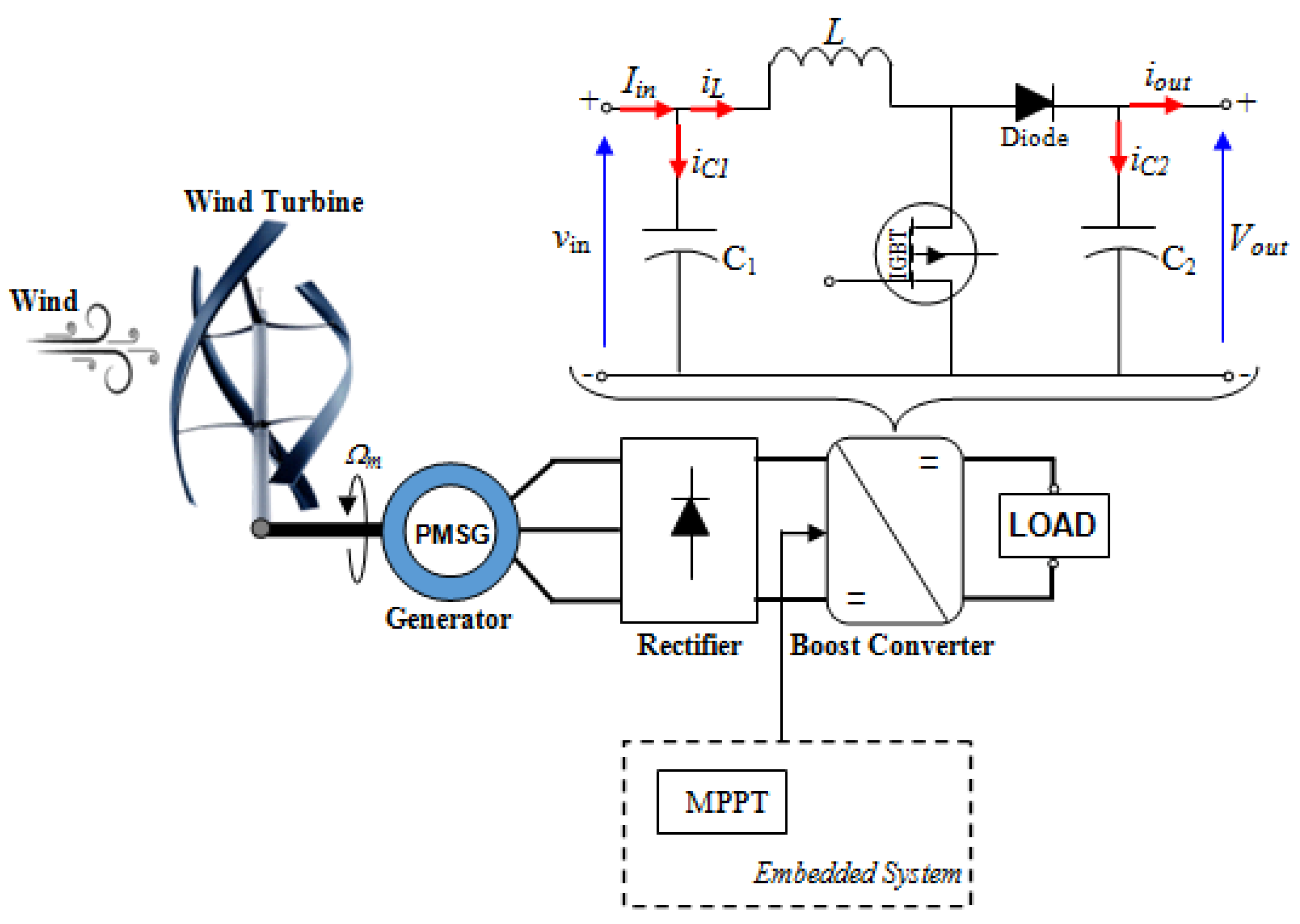
Figure 1. The architecture of the studied wind energy conversion chain.
Symmetry 15 00369 g001
Figure 2. Overall model of the WT.
Symmetry 15 00369 g002
Figure 3. WT characteristics; (a) power as a function of the rotation speed, (b) power coefficient as a function of the relative speed.
Symmetry 15 00369 g003
Figure 4. WT power vs. rotational speed characteristic with the four possible displacement cases.
Symmetry 15 00369 g004
Figure 5. Principle diagram of the control law obtained from the SC.
Symmetry 15 00369 g005
Figure 6. Simulink model of the wind chain studied.
Symmetry 15 00369 g006
Figure 7. Simulation results for the case where the WT’s inertia is not considered: (a) wind speed profile, (b) rotational speed, (c) power coefficient, (d) relative speed, (e) WT’s power, (f) load power, (g) the voltage at the input and at the output of the boost converter, (h) the current at the input and at the output of the boost converter.
Symmetry 15 00369 g007
Figure 8. Simulation results when the WT inertia is taken into account: (a) power coefficient, (b) relative speed, (c) power of WT, (d) rotational speed.
Symmetry 15 00369 g008
Figure 9. Experimental test bench of the wind turbine emulator.
Symmetry 15 00369 g009
Figure 10. Simulink/dSPACE model.
Symmetry 15 00369 g010
Figure 11. Experimental results in the case of consecutive wind speed change with constant electrical load: (a) wind profile applied to the WT, (b) rotational speed, (c) power coefficient, (d) relative speed, (e) power of the WT, (f) power at the terminals of the electrical load.
Symmetry 15 00369 g011
Figure 12. Experimental results in the case of constant wind speed with variable electrical load: (a) wind profile applied to the WT, (b) rotational speed, (c) power coefficient, (d) relative speed, (e) power of the WT, (f) power at the terminals of the electrical load.
Symmetry 15 00369 g012
Figure 13. Experimental results in the case of stochastic wind speed change with constant electrical load: (a) wind profile applied to the WT, (b) power coefficient, (c) power of the WT.
Symmetry 15 00369 g013
Table 1. Parameters used in the experimental validation [38].
ParametersValueUnit
WTNominal power1.5kW
Air density1.2kg/m3
Blade radius1m
Height2m
Moment of inertia5kg·m2
Coefficient of friction0.00908N·m·s/rad
Maximum power coefficient
Maximum relative speed
0.388
4.94
---
rad
MPPT
 
Constant k
Constant T
900
0.0038
---
---
Boost ConverterInput capacitor
Output capacitor
Inductance
Switching frequency
10
1100
50
1
mF
µF
mH
kHz
Disclaimer/Publisher’s Note: The statements, opinions and data contained in all publications are solely those of the individual author(s) and contributor(s) and not of MDPI and/or the editor(s). MDPI and/or the editor(s) disclaim responsibility for any injury to people or property resulting from any ideas, methods, instructions or products referred to in the content.