Article

Variability of Elastic Properties of Two-Layered Tubes from Six-Constant Tetragonal Crystals

by
Mikhail A. Volkov
*,
Valentin A. Gorodtsov
and
Dmitry S. Lisovenko
Ishlinsky Institute for Problems in Mechanics RAS, Prospekt Vernadskogo 101-1, 119526 Moscow, Russia
*
Author to whom correspondence should be addressed.
Symmetry 2023, 15(3), 685; https://doi.org/10.3390/sym15030685
Submission received: 21 November 2022 / Revised: 9 February 2023 / Accepted: 3 March 2023 / Published: 8 March 2023

Abstract

:
An analytical analysis of the problem of the longitudinal tension of two-layered tubes with walls made of tetragonal crystals was carried out together with numerical calculations of the effective Young’s moduli and Poisson’s ratios of the tubes, using the known experimental data on the elastic characteristics of such crystals. The study of the effective elastic properties of two-layered tubes was carried out in the cases of layers of the same thickness, equal volumes, and greater arbitrariness. The effective Young’s modulus often exceeds the largest Young’s modulus of a pair of layers, and the effective Poisson’s ratio can be negative, even if the Poisson’s ratios are positive in both layers. In other words, an auxetic of the two-layered tube may correspond to a pair of non-auxetics in two layers of this tube.

1. Introduction

More than a hundred years ago, material with a negative Poisson’s ratio was discussed for the first time. This material was iron pyrite with elastic properties described in Love’s monograph [1]. More recent studies have not confirmed a negative Poisson’s ratio for this material [2,3]. Extensive investigation of materials with a negative Poisson’s ratio began after publication [4], where metal and polymer foams with a negative Poisson’s ratio were produced. Later, such materials became known as auxetics. They are divided into two groups: artificial materials (metamaterials and nanomaterials) and natural materials (anisotropic materials, such as crystals, zeolites, etc.). Re-entrant hexagonal structures [4,5], chiral structures [6,7], structures from rotating rigid blocks [8,9], triangular [10] and other cellular structures [11,12,13,14] can be attributed to the former category.
The anomalous elastic behavior of the auxetic type among anisotropic materials is widespread. The elastic features of crystals (including auxeticity) depend on their crystal system class number. Cubic crystals belong to the lowest class with three independent elastic parameters. The number of such parameters is doubled for two-layered composites (plates and tubes). Many auxetics are formed among cubic crystals despite the small number of elastic parameters in them. This is due to the wide spread of materials with a cubic structure in nature. Various features of auxetics among cubic crystals are reflected in the following publications: [15,16,17,18,19,20,21,22,23,24,25,26,27,28,29,30,31,32,33]. A change in auxeticity occurs in the presence of defects in cubic crystals. The role of one-dimensional and two-dimensional defects, such as nanochannels and nanolayers, in model cubic crystals has been studied in a number of works: [34,35,36,37,38,39,40,41,42,43,44,45]. The auxeticity of cylindrically anisotropic crystalline tubes from cubic and six-constant tetragonal crystals was investigated partially in [46,47]. It was shown that the number of auxetic tubes exceeds the number of auxetic crystals at the rectilinear anisotropy. The stress–strain state of tubes was supposed to be radially non-uniform. The analytical results were verified by atomistic simulation in [48,49], where for tubes of aluminum, copper and iron, they showed qualitative and, for some potentials, quantitative correspondence between the analytical and numerical results.
Longitudinal tension of two-layered tubes of cubic crystals depends on six defining elastic parameters and, therefore, exhibits many features of auxetic behavior and effective mechanical properties. For example, two-layered tubes produced from pairs of non-auxetics can have large negative effective Poisson’s ratios. The effective elastic properties (Young’s modulus and Poisson’s ratio) of longitudinally deformed two-layered composites of cubic crystals are not described by simple mixture rules [50,51]. The angle between differently oriented layers of a stretchable two-layered plate made of cubic crystals plays an important role in addition to the six elastic parameters. The effective Young’s modulus in this case exceeds Young’s modulus of each of the layers, and the Voigt’s mixture rule fails [52]. The longitudinal tension of two-layered plates formed from cubic and hexagonal crystals is characterized by a slightly larger number of elastic parameters (3+5). This is due to a different class of crystal system for hexagonal crystals. The different orientation of layers with cubic and hexagonal crystals is reflected in an important additional parametric dependence. A significant difference between the effective Young’s modulus and predictions by the mixture rule takes place in the case where one of the layers is auxetic. Significant influence on effective Poisson’s ratio has the ratio of Young’s moduli of cubic and hexagonal crystals [53]. Longitudinal tension of two-layered plates of hexagonal crystals depends on ten elastic parameters. It has been shown that the effective Young’s modulus of such plates always exceeds the results calculated by the Voigt’s mixture rule. Increasing the thickness of the auxetic layer allows to control the value of the negative effective in-plane Poisson’s ratio of a two-layered auxetic–non-auxetic plate [54].
Below, we consider the problem of the longitudinal tension of two-layered tubes filled with unidirectional six-constant tetragonal crystals. The analytical solution of this problem of elasticity theory with twelve elastic parameters is discussed in detail (Section 2). The experimental values of the elastic characteristics of crystals in layers were taken from a well-known handbook [55]. Section 3 is limited to the analysis of some two-layered tubes with equal thickness and volumes of layers. In Section 4, calculations of the effective Young’s modulus and Poisson’s ratio are mode for arbitrary values of the layers thicknesses of two-layered tubes. In the final Section 5, the results of the analysis of the longitudinal tension of two-layered tubular composites from unidirected six-constant tetragonal crystals are presented.

2. Two-Layered Tubes from Six-Constant Tetragonal Crystals under Longitudinal Tension

Let us consider a two-layered tube as pictured in Figure 1. The radial coordinate r changes at r 0 r r i and r i r R 0 for the inner and outer layers, respectively. Each layer consists of material with six-constant tetragonal anisotropy and it requires six independent coefficients (s11, s33, s44, s66, s12, s13) to describe its elastic behavior. Upper indices (1) and (2) will be used to denote the inner and outer layers, respectively. Local correspondence x 1 ( 1 , 2 ) z , x 2 ( 1 , 2 ) φ , x 3 ( 1 , 2 ) r between bases of the crystallophysic and cylindrical coordinate systems takes place for both layers of the tube. Taking into account the aforementioned assumptions, Hooke’s law has the following form:
r 0 r r i u z z ( 1 ) = s 11 ( 1 ) σ z z ( 1 ) + s 12 ( 1 ) σ φ φ ( 1 ) + s 13 ( 1 ) σ r r ( 1 ) u φ φ ( 1 ) = s 12 ( 1 ) σ z z ( 1 ) + s 11 ( 1 ) σ φ φ ( 1 ) + s 13 ( 1 ) σ r r ( 1 ) u r r ( 1 ) = s 13 ( 1 ) σ z z ( 1 ) + σ φ φ ( 1 ) + s 33 ( 1 ) σ r r ( 1 ) 2 u r z ( 1 ) = s 44 ( 1 ) σ r z ( 1 ) 2 u r φ ( 1 ) = s 44 ( 1 ) σ r φ ( 1 ) 2 u φ z ( 1 ) = s 66 ( 1 ) σ φ z ( 1 ) r i r R 0 u z z ( 2 ) = s 11 ( 2 ) σ z z ( 2 ) + s 12 ( 2 ) σ φ φ ( 2 ) + s 13 ( 2 ) σ r r ( 2 ) u φ φ ( 2 ) = s 12 ( 2 ) σ z z ( 2 ) + s 11 ( 2 ) σ φ φ ( 2 ) + s 13 ( 2 ) σ r r ( 2 ) u r r ( 2 ) = s 13 ( 2 ) σ z z ( 2 ) + σ φ φ ( 2 ) + s 33 ( 2 ) σ r r ( 2 ) 2 u r z ( 2 ) = s 44 ( 2 ) σ r z ( 2 ) 2 u r φ ( 2 ) = s 44 ( 2 ) σ r φ ( 2 ) 2 u φ z ( 2 ) = s 66 ( 2 ) σ φ z ( 2 )
With a rigid connection of the two layers of the tube, the displacements at the interface ( r = r i ) are continuous
u r ( 1 ) = u r ( 2 ) , u φ ( 1 ) = u φ ( 2 ) , u z ( 1 ) = u z ( 2 )
The stress components σ r z ( 1 , 2 ) , σ r φ ( 1 , 2 ) , σ φ z ( 1 , 2 ) on the inner ( r = r 0 ) and outer ( r = R 0 ) surfaces of the tube stretched along z-axis are assumed to be equal to zero:
σ r r ( 1 ) ( r 0 ) = σ r r ( 2 ) ( R 0 ) = 0 , σ r φ ( 1 ) ( r 0 ) = σ r φ ( 2 ) ( R 0 ) = 0 , σ r z ( 1 ) ( r 0 ) = σ r z ( 2 ) ( R 0 ) = 0
If there are no integral torques, then the tangential stress components σ r z ( 1 , 2 ) , σ r φ ( 1 , 2 ) , σ φ z ( 1 , 2 ) can be considered negligible over the entire cross-section of the tube. The normal stress components σ z z ( 1 , 2 ) correspond to the specific tensile force P:
r 0 r i 0 2 π σ z z ( 1 ) r d r d φ + r i R 0 0 2 π σ z z ( 2 ) r d r d φ = P r 0 R 0 0 2 π r d r d φ
Only one equation for normal stresses out of three equilibrium equations
σ φ φ ( 1 , 2 ) = d r σ r r ( 1 , 2 ) d r , d r σ r z ( 1 , 2 ) d r = 0 , d r 2 σ r φ ( 1 , 2 ) d r = 0
turns out to be non-trivial under these conditions.
Using the simplified Hooke’s law and the differential equations for the strain components in terms of displacement, we find the following possible type of the latter:
u r ( 1 , 2 ) = r u φ φ ( 1 , 2 ) ( r ) + f 1 ( 1 , 2 ) ( φ ) r + C 1 u φ ( 1 , 2 ) = C 1 ( 1 , 2 ) r d f 1 ( 1 , 2 ) ( φ ) d φ z + d f 2 ( 1 , 2 ) ( φ ) d φ u z ( 1 , 2 ) = ε ( 1 , 2 ) z f 1 ( 1 , 2 ) ( φ ) r + f 2 ( 1 , 2 ) ( φ ) f 1 ( 1 , 2 ) = C 2 ( 1 , 2 ) cos φ + C 3 ( 1 , 2 ) sin φ , f 2 ( 1 , 2 ) = C 4 ( 1 , 2 ) cos φ + C 5 ( 1 , 2 ) sin φ u z z ( 1 ) = ε ( 1 ) = c o n s t , u z z ( 2 ) = ε ( 2 ) = c o n s t , C i = c o n s t
Single-valued displacements require the following restriction on the strain:
u r r ( 1 , 2 ) = d ( r u φ φ ( 1 , 2 ) ) d r
Restrictions (2) and (7) lead to the following relations between the strains:
u φ φ ( 1 ) ( r i ) = u φ φ ( 2 ) ( r i ) , u r r ( 1 ) ( r i ) u r r ( 2 ) ( r i ) , u z z = ε = ε ( 1 ) = ε ( 2 )
Using Hooke’s law (1), equilibrium Equation (5) and restriction on the strains (7), it is possible to obtain the radial component of the stress field of the tube:
σ r r ( 1 , 2 ) ( r ) = a 1 ( 1 , 2 ) + a + ( 1 , 2 ) r r i λ + ( 1 , 2 ) + a ( 1 , 2 ) r r i λ ( 1 , 2 ) ε
Here,
a 1 ( 1 , 2 ) = s 12 ( 1 , 2 ) s 13 ( 1 , 2 ) s 33 ( 1 , 2 ) s 11 ( 1 , 2 ) + s 12 ( 1 , 2 ) 2 s 13 ( 1 , 2 ) 2 s 11 ( 1 , 2 ) 2 λ ± ( 1 , 2 ) = 1 ± k ( 1 , 2 ) , k ( 1 , 2 ) = s 33 ( 1 , 2 ) s 11 ( 1 , 2 ) s 13 ( 1 , 2 ) 2 s 11 ( 1 , 2 ) 2 s 12 ( 1 , 2 ) 2
Coefficients a ± ( 1 , 2 ) are defined by a system of linear equations which follows from boundary condition (3) for σ r r ( 1 , 2 ) :
A a + ( 1 ) a ( 1 ) a + ( 2 ) a ( 2 ) = b
Here,
A = 1 / ρ 1 λ + ( 1 ) 1 / ρ 1 λ ( 1 ) 0 0 0 0 ρ 2 λ + ( 2 ) ρ 2 λ ( 2 ) 1 1 1 1 Λ + ( 1 ) Λ ( 1 ) Λ + ( 2 ) Λ ( 2 )
b = a 1 ( 1 ) a 1 ( 2 ) a 1 ( 2 ) a 1 ( 1 ) s 12 ( 2 ) s 11 ( 2 ) + a 1 ( 2 ) t 11 ( 2 ) + t 13 ( 2 ) s 12 ( 1 ) s 11 ( 1 ) a 1 ( 1 ) t 11 ( 1 ) + t 13 ( 1 ) ,
where
Λ ± ( 1 , 2 ) = t 13 ( 1 , 2 ) ± k ( 1 , 2 ) t 11 ( 1 , 2 ) t 11 ( 1 , 2 ) = s 11 ( 1 , 2 ) s 12 ( 1 , 2 ) 2 s 11 ( 1 , 2 ) , t 13 ( 1 , 2 ) = s 13 ( 1 , 2 ) s 12 ( 1 , 2 ) s 13 ( 1 , 2 ) s 11 ( 1 , 2 ) ρ 1 = r i r 0 , ρ 2 = R 0 r i , ρ = R 0 r 0 = ρ 1 ρ 2
Coefficients a ± ( 1 , 2 ) can be obtained either analytically or numerically. In the article, it is supposed that the coefficients are obtained numerically. A detailed solution to the discussed problem and analytical expressions for the coefficients a ± ( 1 , 2 ) are presented in Appendix A. The remaining components of the stress field can be expressed through the σ r r ( 1 , 2 ) using the simplified Hooke’s law (1). With the use of boundary conditions (4) on σ z z , Young’s modulus E = P / ε and Poisson’s ratios (effective) ν φ z = u φ φ / u z z and ν r z = u r r / u z z can be defined as follows:
E = 1 s 11 ( 1 ) [ 1 a 1 ( 1 ) ( s 12 ( 1 ) + s 13 ( 1 ) ) 1 1 / ρ 1 2 ρ 2 2 1 / ρ 1 2 ± 2 s 13 ( 1 ) + 2 + λ ± ( 1 ) s 12 ( 1 ) λ ± ( 1 ) + 2 a ± ( 1 ) 1 1 / ρ 1 λ ± ( 1 ) + 2 ρ 2 2 1 / ρ 1 2 ] + 1 s 11 ( 2 ) [ 1 a 1 ( 2 ) ( s 12 ( 2 ) + s 13 ( 2 ) ) ρ 2 2 1 ρ 2 2 1 / ρ 1 2 ± 2 s 13 ( 2 ) + 2 + λ ± ( 2 ) s 12 ( 2 ) λ ± ( 2 ) + 2 a ± ( 2 ) ρ 2 λ ± ( 2 ) + 2 1 ρ 2 2 1 / ρ 1 2 ]
ν φ z ( 1 , 2 ) = [ s 12 ( 1 , 2 ) s 11 ( 1 , 2 ) + a 1 ( 1 , 2 ) ( t 13 ( 1 , 2 ) + t 11 ( 1 , 2 ) ) + ± t 13 ( 1 , 2 ) + ( 1 + λ ± ( 1 , 2 ) ) t 11 ( 1 , 2 ) a ± ( 1 , 2 ) ξ λ ± ( 1 , 2 ) ]
ν r z ( 1 , 2 ) = [ s 13 ( 1 , 2 ) s 11 ( 1 , 2 ) + a 1 ( 1 , 2 ) t 33 ( 1 , 2 ) + t 13 ( 1 , 2 ) + ± t 33 ( 1 , 2 ) + ( 1 + λ ± ( 1 , 2 ) ) t 13 ( 1 , 2 ) a ± ( 1 , 2 ) ξ λ ± ( 1 , 2 ) ]
Here, ξ = r / r i —dimensionless radial coordinate. Variability analysis is presented below for Young’s modulus and Poisson’s ratios of two-layered tubes from tetragonal crystals. In the handbook [55], elasticity coefficients are collected for more than 90 tetragonal crystals. Excluding tubes with the same material in both layers, for the elastic properties, 9506 combinations were analyzed. The further analysis considers tubes from all possible combinations of tetragonal crystals. In the present research, crystals with negative s 12 / s 11 or s 13 / s 11 are considered auxetic. According to [55], there are 26 crystals with s 12 > 0 or s 13 > 0 . Here and after, the values
E ( i ) = 1 s 11 ( i ) , ν 12 ( i ) = s 12 ( i ) s 11 ( i ) , ν 13 ( i ) = s 13 ( i ) s 11 ( i ) , i = 1 , 2
are named the Young’s modulus and Poisson’s ratio of the layers, correspondingly. Values of these engineering constants for the discussed materials are provided in Table 1.

3. Elastic Properties of Two-Layered Six-Constant Tetragonal Tubes with Equal Thicknesses and Volumes of Layers

In the present section, two particular cases of tube geometry are considered: tubes with equal thicknesses and equal volumes of layers. To be considered as a tube with equal thicknesses of layers h 1 = r i r 0 and h 2 = R 0 r i , the following relation between thickness parameters ρ 1 and ρ 2 has to be met:
ρ 1 = 1 2 ρ 2 , 1 < ρ 1 , 1 < ρ 2 < 2 .
In the case of tubes with equal volumes of layers, values of the thickness parameters are restricted by the following relations:
R 0 2 r i 2 = r i 2 r 0 2 , ρ 1 = 1 2 ρ 2 2 , 1 < ρ 1 , 1 < ρ 2 < 2
In the situation considered here, we are discussing tubes with thickness parameters ρ 1 = 1.11 , ρ 1 = 2 and ρ 1 = 10 , which correspond to ρ 2 = 1.1 , ρ 2 = 1.5 and ρ 2 = 1.9 for tubes with equal thickness of layers. In the case of tubes with equal volumes of layers, the same values of ρ 1 correspond to ρ 2 = 1.09 , ρ 2 = 1.32 and ρ 2 = 1.41 , respectively. The overall thickness of tube ρ is greater for tubes with layers of equal thickness. It equals ρ = 1.22 ; 3 ; 19 and ρ = 1.21 ; 2.65 ; 14.1 for ρ 1 = 1.11 ; 2 ; 10 for the cases of equal thicknesses and volumes, respectively. For the following discussion, it is convenient to denote Young’s modulus of the tube with equal thicknesses of layers as E t h , with equal volumes of layers as E v r and the largest Young’s modulus of layers as E max ( 1 , 2 ) = max ( E ( 1 ) , E ( 2 ) ) .
On average, among all materials combinations, ratios E t h / E max ( 1 , 2 ) and E v r / E max ( 1 , 2 ) have close values. They equal E t h / E max ( 1 , 2 ) = 0.7155; 0.7214; 0.7364 and E v r / E max ( 1 , 2 ) = 0.7154; 0.7194; 0.7363 for ρ 1 = 1.11; 2; 10, correspondingly. The difference in average values is significant if we consider two particular cases: E ( 2 ) > E ( 1 ) and E ( 2 ) < E ( 1 ) . In the first case, the ratios are 0.72, 0.80, 0.88 and 0.71, 0.72, 0.73 for ρ 1 = 1.11, 2, 10 for E t h / E max ( 1 , 2 ) and E v r / E max ( 1 , 2 ) , respectively. The average ratio of Young’s moduli E t h / E v r also increases with ρ 1 : 1.03, 1.12 and 1.22 for ρ 1 1.11, 2 and 10. When the inner layer is stiffer, the ratios of Young’s modulus to E max ( 1 , 2 ) are equal 0.69, 0.64, 0.68 and 0.71, 0.72, 0.73. The average ratio of Young’s moduli is 0.97, 0.88 and 0.77 for ρ 1 = 1.11, 2 and 10. The presence of an auxetic layer has no influence on the average values of Young’s modulus.
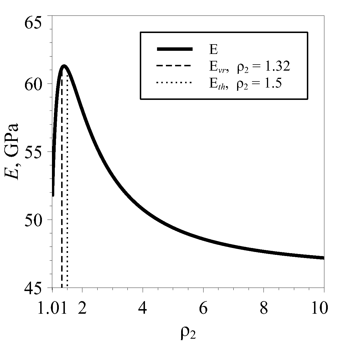
For some tubes, Young’s modulus exceeds the largest Young’s modulus of layers E max ( 1 , 2 ) . The number of such tubes is relatively small. There are 405, 539 and 823 for ρ 1 equal to 1.11, 2 and 10 in the case of equal thicknesses of the layers. In the case of equal volumes, the numbers are 396, 487 and 710, correspondingly. All of these tubes are characterized by close values of E ( 1 ) and E ( 2 ) or by a large difference between ν 12 ( 1 ) and ν 12 ( 2 ) . Values of Young’s modulus for different combinations are presented in Table 2 for tubes with equal thicknesses and volumes of layers. For some tubes, the maximum value of Young’s modulus can correspond to a distinctive peak value, as it happens for tube CoF2–RbH2AsO4 (Figure 2). On this figure, the value of Young’s modulus E is presented over the relative thickness of the second layer ρ 2 at the fixed thickness of the first layer ρ 1 . For the majority of the tubes, Young’s modulus E changes monotonously under the same conditions. It shows that certain combinations of materials allow enhanced effective properties for relatively low overall thickness.
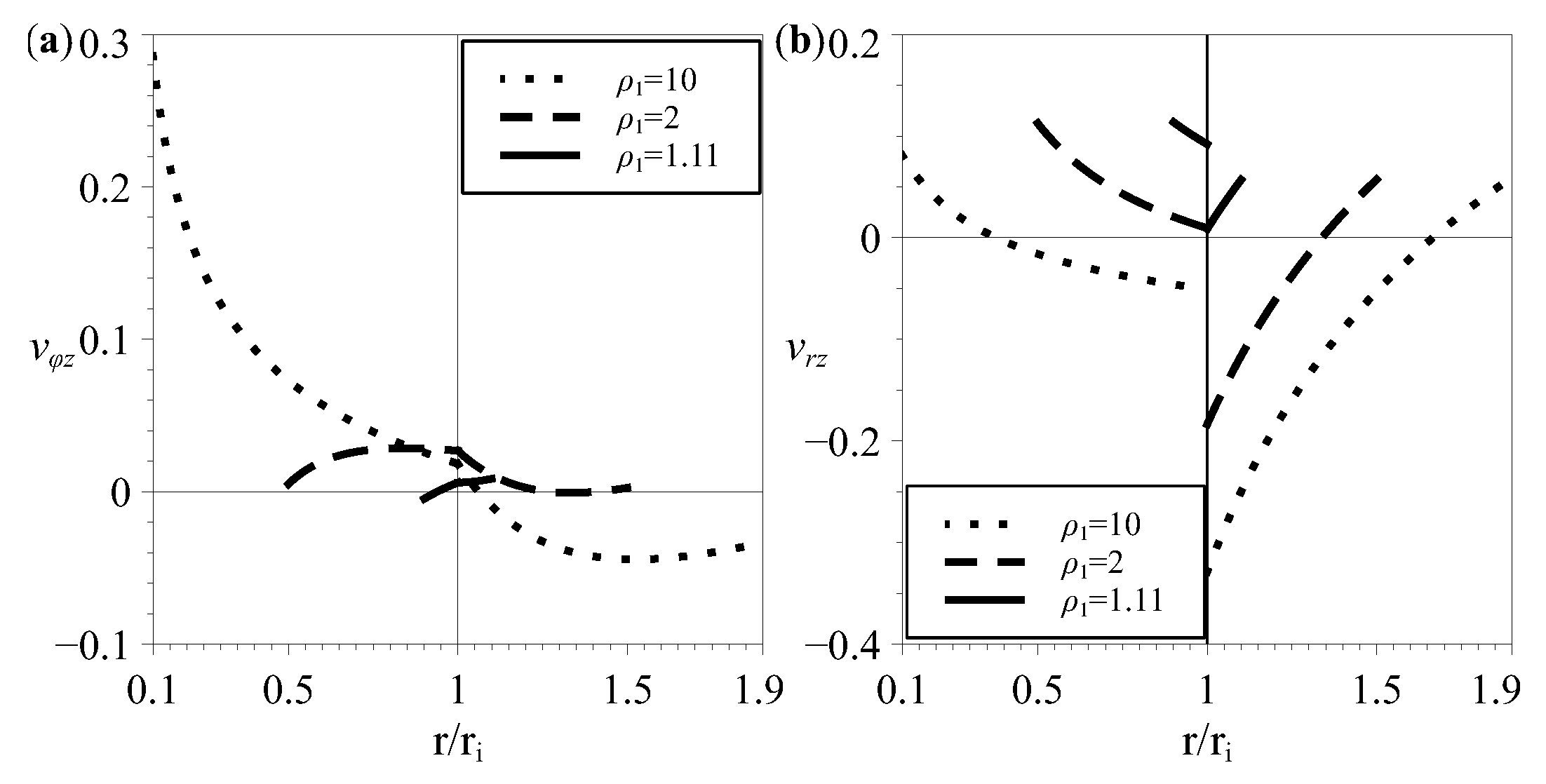
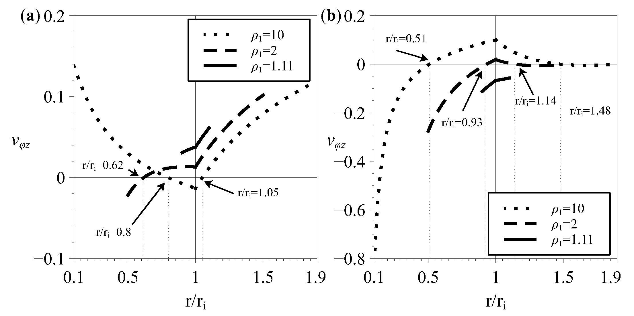
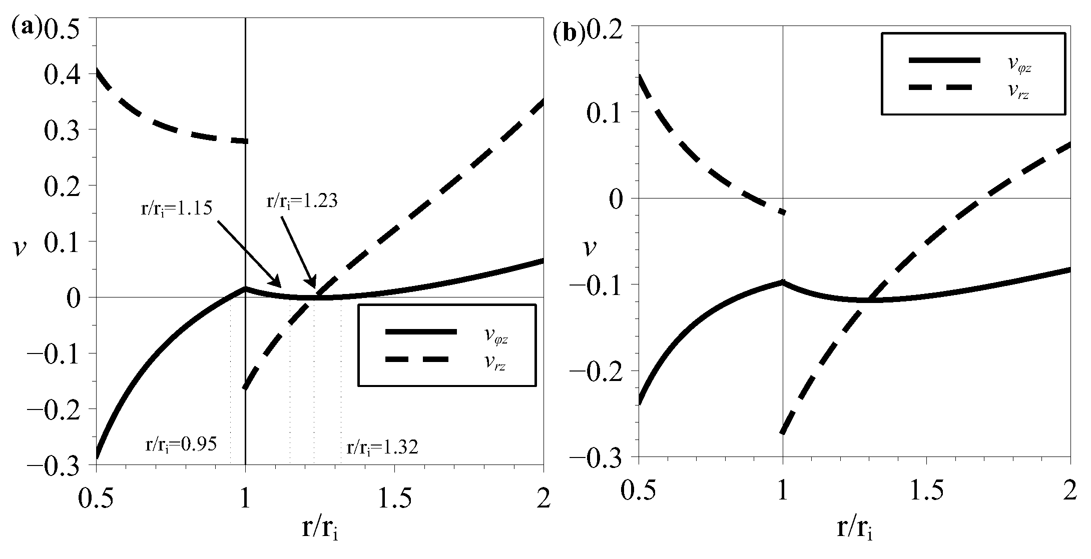
Poisson’s ratio ν φ z can be negative for some tubes with equal thicknesses of layers. There are 1349 tubes with negative ν φ z for ρ 1 = 1.11, 2667 for ρ 1 = 2 and 3896 for ρ 1 = 10, including tubes from a pair of non-auxetic crystals. There are 46 such combinations for ρ 1 = 1.11, 469 for ρ 1 = 2 and 1091 for ρ 1 = 10. Poisson’s ratios explicitly depend on the dimensionless radial coordinate ξ = r / r i and are defined within the range [ 1 / ρ 1 , ρ 2 ] for corresponding values of the thickness parameters. Its value can change significantly with the radial coordinate, and the variety of its behavior will be discussed below. The majority of auxetic tubes have an area of negative Poisson’s ratio located near one of the surfaces and the Poisson’s ratio becomes positive within the corresponding layer. For some tubes, the change of the sign of Poisson’s ratio can take place within the other layer, or it can be negative within whole thickness. The majority of auxetic tubes have an auxetic area near the inner surface, such as, for example CsH2AsO4–FeGe2 (Figure 3a). Every analyzed tube with negative ν φ z consists of crystals with a large difference in the Young’s moduli of the layers. Many of them have crystals of In and TI alloys(InTl, InCd, InPb) for the inner layer and a stiff material (WSi2, ZrSiO4) for the outer layer. A fewer amount of tubes have Poisson’s ratio ν φ z as being negative over the thickness. The number of fully auxetic tubes is 747 for ρ 1 = 1.11, 139 for ρ 1 = 2 and 56 for ρ 1 = 10. This behavior can be seen in the example of tube CsH2AsO4–FeGe2 (Figure 3a) for ρ 1 = 1.11 and FeGe2–RbH2AsO4 (Figure 3b) for various ρ 1 . The lowest values of ν φ z are achieved for the tube (NH2)2CO–RbD2AsO4. The minimal and maximal values of this Poisson’s ratio are equal to 0.49 ; 0.38 for ρ 1 = 1.11, 1.40 ; 0.34 for ρ 1 = 2 and 5.56 ; 0.11 for ρ 1 = 10. Only four combinations for ρ 1 = 2 and 13 combinations for ρ 1 = 10 have negative ν φ z near the outer surface.
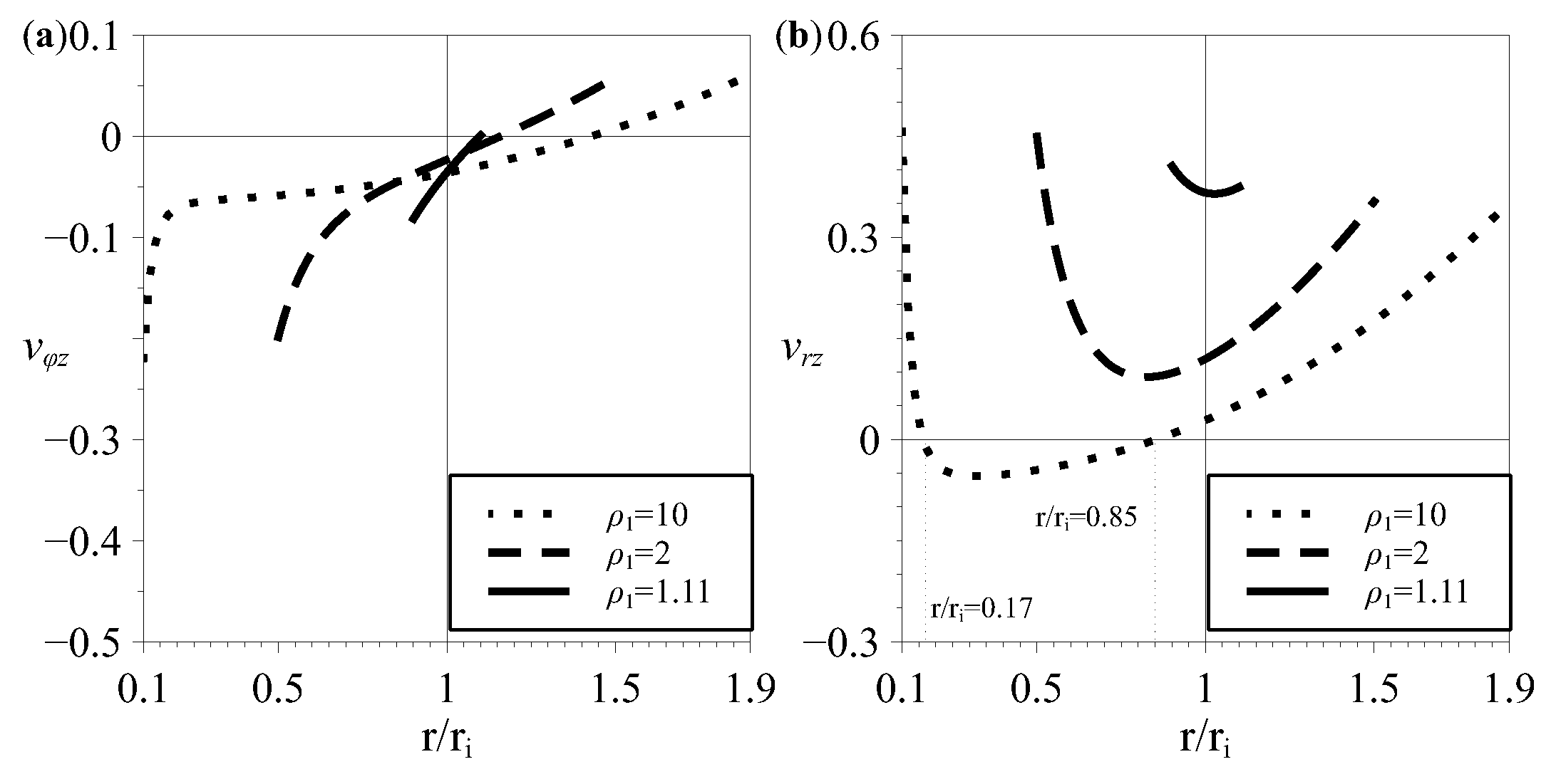
Poisson’s ratio ν r z , due to its discontinuity at the interface, is characterized by non-monotonous behavior over the thickness. There are 524, 1417 and 3187 tubes with negative ν r z for ρ 1 = 1.11, 2 and 10, respectively. The location of the auxetic area can be different. It can be located near one of the tube surfaces or interface. Examples of such behavior are tubes Ba2Si2TiO8, ( s E )–WSi2 (Figure 4a) and CsH2AsO4–Ba2Si2TiO8, ( s E ) (Figure 4b). There are no tubes found with ν r z negative over the whole thickness. There are also tubes with negative ν r z with positive ν 12 ( i ) and ν 13 ( i ) for both layers. There are 58 tubes for ρ 1 = 1.11, 659 for ρ 1 = 2 and 1490 for ρ 1 = 10 in the case of tubes with equal thicknesses of layers. In the case of equal volumes of layers, the number of such tubes is 49, 571 and 1533 for ρ 1 = 1.11, 2 and 10, respectively. Tube CoF2–Zr2Ni is an example of this behavior with both crystals having positive Poisson’s ratios and relatively close values of the Young’s modulus (see Table 1). For this tube, value ν r z reaches 0.57 for ρ 1 = 10 and the small auxetic area: Poisson’s ratio becomes positive for ξ = r / r i > 0.15 . Some of the tubes with ν r z < 0 do not change its sign at the interface. The number of such tubes is 25, 664 and 1937 for ρ 1 = 1.11, 2 and 10, correspondingly. Tubes of crystals CsNiF3–RbH2AsO4 (Figure 5) illustrate such behavior.
In the case of tubes with equal volumes of layers, the difference with the case of equal thicknesses is only quantitative. There are 1336, 2652 and 3875 tubes with ν φ z for ρ 1 = 1.11, 2 and 10, respectively. The number of fully auxetic tubes is 747 for ρ 1 = 1, 139 for ρ 1 = 2 and 56 for ρ 1 = 10. This is also correct for Poisson’s ratio ν r z of tubes with equal volumes. There were found 692 tubes with ν r z < 0 for ρ 1 = 1.11, 1543 for ρ 1 = 2 and 3102 for ρ 1 = 10.
Except for the aforementioned cases, the auxetic area can be located in such a way that the inner or outer surface of the tube is not included. In this case, Poisson’s ratio will change sign multiple times within the thicknesses of the tube, as it is for CsNiF3–LuAsO4 on Figure 6a. In the present analysis, Poisson’s ratio ν φ z for tubes with equal thicknesses of layers changes its sign 2 or more times for 9 combinations when ρ 1 = 2 and 53 when ρ 1 = 10. There are no such tubes found for ρ 1 = 1.11. Tubes CsNiF3–LuAsO4 (Figure 6a) and LuAsO4–RbH2AsO4 (Figure 6b) show the particular case of an area with negative ν φ z that includes the interface and typical case of multiple roots for ν φ z , respectively. On this and the following figures, thin dotted lines show points where Poisson’s ratio is equal to zero. They also can be interpreted as a boundary between auxetic and non-auxetic areas within a tube. Other examples of non-monotonous behavior are tubes FeGe2–RbH2AsO2 (Figure 3b) and Ba2Si2TiO8, ( s E )–WSi2 (Figure 4a). Poisson’s ratio ν r z also exhibits such non-monotonous behavior. It was found for 41 tubes for ρ 1 = 2 and 134 tubes for ρ 1 = 10 when the thicknesses of the layers are equal. In the example of tubes HgI2–RbH2AsO4 (Figure 7), ν r z can change its sign multiple times, even within a layer. Non-monotonous behavior is also observed for homogeneous tubes from six-constant tetragonal crystals, as it can be seen in the example of FeGe2 tube (Figure 8).

4. Effective Properties Variability for Two-Layered Tubes from Six-Constant Tetragonal Crystals with Arbitrary Thicknesses of Layers

In this section, the results of the analysis are discussed for the case of thickness parameters ρ 1 and ρ 2 varying within the range [1.01, 2].
Young’s modulus exceeds E max by more than 5% for 593 of the analyzed combinations. Values of Young’s modulus for some tubes are presented in Table 3, where values of ρ 1 and ρ 2 corresponding to the maximum are also presented. For analyzed tubes, the extrema of Young’s modulus correspond to the ends of the range [1.01, 2].
Poisson’s ratio ν φ z is negative for 5010 combinations, and its extreme values correspond to one of the surfaces or the interface. More than 1000 of them are fully auxetic. There are 5 tubes for which the sign of the Poisson’s ratio changes twice and one (LuAsO4–FeGe2) with the change of sign occurring three times (Figure 9a). It also can be noticed from Figure 9a, that the tube has the area where ν r z and ν φ z are simultaneously negative. These materials have close values of Young’s moduli and a close to zero negative Poisson’s ratio (see Table 1). The majority of fully auxetic tubes correspond to a combination of a thin layer ( ρ = 1.01) with a positive Poisson’s ratio and a thick auxetic layer ( ρ = 2). Young’s moduli can differ by dozens of GPa. Values of Poisson’s ratio ν r z can be negative for 2948 tubes, and almost every of them (2369) are tubes from crystals with positive ν 13 . There is a significant number of tubes (1488 combinations) with negative ν r z which do not change their sign at the interface. Tube CsNiF3–RbH2AsO4 is an example (Figure 9b) of such behavior. The major difference from the case of equal thicknesses (Figure 5) is that this tube has negative ν φ z over the thickness and simultaneously negative Poisson’s ratios for some values of dimensionless radial coordinate ξ .
The extrema of Young’s modulus and Poisson’s ratios of some tubes can correspond to values of thickness parameters ρ 1 and ρ 2 different from 1.01 and 2. The maximum of Young’s modulus corresponds to the intermediate value of ρ 1 or ρ 2 for 461 tubes, some of which are listed in Table 3. The same behavior takes place for the minimum of Poisson’s ratio ν φ z for 384 tubes and 613 for the maximum. In the case of Poisson’s ratio ν r z , the number of such tubes is 1808 and 1959 for the minimum and maximum, correspondingly. In Table 4 and Table 5, the values of Poisson’s ratios ν φ z and ν r z and corresponding values of thickness parameters and dimensionless radial coordinate ξ are presented.

5. Conclusions

Analytical analysis and numerical processing of the longitudinal elastic tension of two-layered tubes from six-constant tetragonal crystals were performed. It was found that the effective Young’s modulus of two-layered tubes with different layer thicknesses exceeds the Young’s moduli of both layers in many cases. The effective Poisson’s ratio becomes even more negative in such a situation (that is, the composite will be an auxetic). It was also found that the effective Poisson’s ratio is negative for many non-auxetic pairs in the layers of the same thickness, and effective Poisson’s ratios can change sign several times over the tube cross section.
An important influence on the variability of the elastic properties of tubes of two crystalline layers is exerted by their mutual angular orientation. The relative rotation of the crystals layers around the common axis of the tube by some angle (the angle of chirality) causes the effect of tension on the torsion and vice versa. This requires further research.

Author Contributions

Conceptualization, M.A.V.; software, M.A.V.; validation, M.A.V.; formal analysis, M.A.V.; writing—original draft preparation, M.A.V., V.A.G., D.S.L.; writing—review and editing, V.A.G., D.S.L.; visualization, M.A.V. All authors have read and agreed to the published version of the manuscript.

Funding

The study was supported by the government program (contract 123021700045-7).

Data Availability Statement

The numerical data used to support the findings of this study are included within the article.

Conflicts of Interest

The authors declare no conflict of interest.

Appendix A. Detailed Solution to the Problem of Longitudinal Tension of Two-Layered Tubes from Six-Constant Tetragonal Crystals

Differential relations between the displacement and strain fields have the following form for a cylindrical coordinate system:
u r ( r , φ , z ) r = u r r ( r ) , u z ( r , φ , z ) z = u z z ( r ) 1 r u φ ( r , φ , z ) φ + u r ( r , φ , z ) r = u φ φ ( r ) 1 r u r ( r , φ , z ) φ + r r u φ ( r , φ , z ) r = 2 u r φ ( r ) u φ ( r , φ , z ) z + 1 r u z ( r , φ , z ) φ = 2 u φ z ( r ) u r ( r , φ , z ) z + u z ( r , φ , z ) r = 2 u r z ( r )
Integration of the second, fifth and sixth relations gives the following expressions for the displacement components:
u z ( r , φ , z ) = u z z r + g 1 ( r , φ ) u φ ( r , φ , z ) = 2 u φ z ( r ) z z r g 1 ( r , φ ) φ + g 2 ( r , φ ) u r ( r , φ , z ) = u z z ( r ) r z 2 2 g 1 ( r , φ ) r 2 u r z ( r ) z + g 3 ( r , φ )
Here, g i ( r , φ ) are functions of radial and angular coordinates, which will be determined later. After constitution of (A2) into the remaining Equation (A1) and grouping the results on degrees of z, we obtain the following systems of equations:
d 2 u z z ( r ) d r 2 = 0 d u z z ( r ) d r = 0 2 u r z ( r ) r = 2 g 1 ( r , φ ) r 2 1 r 2 2 g 1 ( r , φ ) φ 2 1 r g 1 ( r , φ ) r + u r z ( r ) = 0 u φ z ( r ) r u φ z ( r ) r 2 r φ g 1 ( r , φ ) r = 0 u r r ( r ) = g 3 ( r , φ ) r r u φ φ ( r ) = g 2 ( r , φ ) φ + g 3 ( r , φ ) 2 u r φ ( r ) = r r g 2 ( r , φ ) r + 1 r g 3 ( r , φ ) φ
It can be seen from the first system that the longitudinal strain u z z ( r ) is constant. With use of the first equation of the second system (A3), g 1 has the following form:
g 1 ( r , φ ) = 2 u r z ( r ) d r + r A 1 cos φ + A 2 sin φ + A 3 φ + A 4 , A i = c o n s t
Substitution of g 1 ( r , φ ) into the third equation of the same system defines the u φ z strain component:
d d r u φ z ( r ) r = A 3 r , 2 u φ z ( r ) = A 3 r 1 + A 5 r , A i = c o n s t
Integration of the first equation of the third system (A3) gives
g 3 ( r , φ ) = u r r ( r ) d r + F ( φ )
The difference of the second and the third equations of the system, after differentiation on r and φ correspondingly, leads to the following equality:
r d d r 1 u r r ( r ) d r r u φ φ ( r ) = d 2 d φ 2 + 1 F ( φ )
This equality is possible only when both sides are equal to a constant ( A 6 ), which leads to the following expressions:
F ( φ ) = A 7 cos φ + A 8 sin φ + A 6 , u r r ( r ) d r r u φ φ ( r ) = A 9 r A 6
The third equation of the third system (A3), (A6) and (A8) gives function g 2 :
g 2 ( r , φ ) = r 2 u r φ ( r ) r d r + d F ( φ ) d φ + K ( φ ) r
The function K ( φ ) can be determined from the third equation of the third system, (A9) and (A6):
K ( φ ) = A 9 φ + A 10
Single-valued displacements require
A 3 = 0 , A 9 = 0
Taking into account (A2)–(A11), the displacement field for each layer is expressed as follows:
u z = ε z + 2 u r z ( r ) d r r f 1 ( φ ) + C 0 u φ = τ r z + C 1 r + z d f 1 ( φ ) d φ + d f 2 ( φ ) d φ + r 2 u r φ ( r ) r d r u r = r u φ φ ( r ) + z f 1 ( φ ) + f 2 ( φ )
Here,
f 1 ( φ ) = F 1 cos φ + F 2 sin φ , f 2 ( φ ) = F 3 cos φ + F 4 sin φ F i = c o n s t , C i = c o n s t , ε = u z z = c o n s t , τ r = 2 u φ z ( r )
Second expression of (A8), taking into account (A11), can be presented in the following form:
u r r ( r ) = d d r r u φ φ ( r )
These expressions for displacement field are obtained under the assumption of the radially nonuniform stress–strain state and are valid for each layer of the two-layered tube. It is supposed that displacements are continuous at the interface r = r i . Requirement
u r ( 1 ) = u r ( 2 ) , u φ ( 1 ) = u φ ( 2 ) , u z ( 1 ) = u z ( 2 )
leads to requiring the equality of every coefficient in the displacement expression:
F 1 ( 1 ) ( φ ) = F 1 ( 2 ) ( φ ) , F 2 ( 1 ) ( φ ) = F 2 ( 2 ) ( φ ) , C i ( 1 ) = C i ( 2 ) ε ( 1 ) = ε ( 2 ) = ε , τ ( 1 ) = τ ( 2 ) = τ , u φ φ ( 1 ) ( r ) = u φ φ ( 2 ) ( r )
This leads to the following relations between the strains:
u φ φ ( 1 ) ( r i ) = u φ φ ( 2 ) ( r i ) , u r r ( 1 ) ( r i ) u r r ( 2 ) ( r i ) , u z z = ε = ε ( 1 ) = ε ( 2 )
From Hooke’s law, the stress component σ r r ( 1 , 2 ) can be expressed as follows:
σ z z ( 1 , 2 ) = 1 s 11 ( 1 , 2 ) ε ( 1 , 2 ) s 12 ( 1 , 2 ) σ φ φ ( 1 , 2 ) s 13 ( 1 , 2 ) σ r r ( 1 , 2 )
Using this expression, the strain components u φ φ ( 1 , 2 ) , u r r ( 1 , 2 ) can be expressed as follows:
u φ φ ( 1 , 2 ) = s 12 ( 1 , 2 ) s 11 ( 1 , 2 ) ε + s 11 ( 1 , 2 ) s 12 ( 1 , 2 ) 2 s 11 ( 1 , 2 ) σ φ φ ( 1 , 2 ) + s 13 ( 1 , 2 ) s 12 ( 1 , 2 ) s 13 ( 1 , 2 ) s 11 ( 1 , 2 ) σ r r ( 1 , 2 ) u r r ( 1 , 2 ) = s 13 ( 1 , 2 ) s 11 ( 1 , 2 ) ε + s 13 ( 1 , 2 ) s 12 ( 1 , 2 ) s 13 ( 1 , 2 ) s 11 ( 1 , 2 ) σ φ φ ( 1 , 2 ) + s 33 ( 1 , 2 ) s 13 ( 1 , 2 ) 2 s 11 ( 1 , 2 ) σ r r ( 1 , 2 )
It is convenient to use notations
t 11 ( 1 , 2 ) = s 11 ( 1 , 2 ) s 12 ( 1 , 2 ) 2 s 11 ( 1 , 2 ) , t 13 ( 1 , 2 ) = s 13 ( 1 , 2 ) s 12 ( 1 , 2 ) s 13 ( 1 , 2 ) s 11 ( 1 , 2 ) , t 33 ( 1 , 2 ) = s 33 ( 1 , 2 ) s 13 ( 1 , 2 ) 2 s 11 ( 1 , 2 )
Using (A14), (5) and (A13), the system of differential equations for the stress components σ r r ( 1 , 2 ) can be obtained:
d d r r d d r r σ r r ( 1 , 2 ) k ( 1 , 2 ) 2 σ r r ( 1 , 2 ) + s 12 ( 1 , 2 ) s 13 ( 1 , 2 ) s 11 ( 1 , 2 ) 2 s 12 ( 1 , 2 ) 2 ε = 0
The solution to such equations has the form
σ r r ( r ) = A 1 ε + A + r 1 + k + A r 1 k
After constitution of the general solution to the differential equations, the stress component for each layer can be written as
σ r r ( 1 , 2 ) ( r ) = a 1 ( 1 , 2 ) + a + ( 1 , 2 ) r r i λ + ( 1 , 2 ) + a ( 1 , 2 ) r r i λ ( 1 , 2 ) ε
Here,
a 1 ( 1 , 2 ) = s 12 ( 1 , 2 ) s 13 ( 1 , 2 ) s 33 ( 1 , 2 ) s 11 ( 1 , 2 ) + s 12 ( 1 , 2 ) 2 s 13 ( 1 , 2 ) 2 s 11 ( 1 , 2 ) 2 λ ± ( 1 , 2 ) = 1 ± k ( 1 , 2 ) , k ( 1 , 2 ) = s 33 ( 1 , 2 ) s 11 ( 1 , 2 ) s 13 ( 1 , 2 ) 2 s 11 ( 1 , 2 ) 2 s 12 ( 1 , 2 ) 2
Coefficients a ± ( 1 , 2 ) can be obtained from boundary conditions (3), and requirements on radial stress σ r r and angular strain u φ φ are continuous at the interface r = r i . The leads to the system of Equation (9):
A a + ( 1 ) a ( 1 ) a + ( 2 ) a ( 2 ) = b
Here
A = 1 / ρ 1 λ + ( 1 ) 1 / ρ 1 λ ( 1 ) 0 0 0 0 ρ 2 λ + ( 2 ) ρ 2 λ ( 2 ) 1 1 1 1 Λ + ( 1 ) Λ ( 1 ) Λ + ( 2 ) Λ ( 2 )
b = a 1 ( 1 ) a 1 ( 2 ) a 1 ( 2 ) a 1 ( 1 ) s 12 ( 2 ) s 11 ( 2 ) + a 1 ( 2 ) t 11 ( 2 ) + t 13 ( 2 ) s 12 ( 1 ) s 11 ( 1 ) a 1 ( 1 ) t 11 ( 1 ) + t 13 ( 1 ) ,
where
Λ ± ( 1 , 2 ) = t 13 ( 1 , 2 ) ± k ( 1 , 2 ) t 11 ( 1 , 2 ) ρ 1 = r i r 0 , ρ 2 = R 0 r i , ρ = R 0 r 0 = ρ 1 ρ 2
The coefficients a ± ( 1 , 2 ) can be obtained by the elimination of variables, for example, and have the form
B a + ( 1 ) = s 12 ( 2 ) s 11 ( 2 ) s 12 ( 1 ) s 11 ( 1 ) 1 ρ 2 2 k ( 2 ) + + a 1 ( 1 ) t 13 ( 2 ) t 13 ( 1 ) ρ 1 λ + ( 1 ) 1 ρ 1 λ ( 1 ) 1 ρ 2 λ ( 2 ) λ + ( 2 ) a 1 ( 1 ) t 11 ( 2 ) k ( 2 ) 1 + ρ 2 2 k ( 2 ) ρ 1 λ + ( 1 ) 1 ρ 1 λ ( 1 ) + + a 1 ( 1 ) t 11 ( 1 ) k ( 1 ) ρ 1 λ ( 1 ) 1 ρ 2 2 k ( 2 ) a 1 ( 2 ) t 11 ( 2 ) 2 k ( 2 ) ρ 2 λ + ( 2 ) + λ ( 2 ) λ + ( 2 ) ρ 2 2 k ( 2 ) ρ 1 2 k ( 1 )
B a ( 1 ) = s 12 ( 2 ) s 11 ( 2 ) s 12 ( 1 ) s 11 ( 1 ) 1 ρ 2 2 k ( 2 ) a 1 ( 1 ) t 13 ( 2 ) t 13 ( 1 ) 1 ρ 2 2 k ( 2 ) 1 ρ 1 λ + ( 1 ) a 1 ( 1 ) t 11 ( 2 ) k ( 2 ) 1 + ρ 2 2 k ( 2 ) 1 ρ 1 λ + ( 1 ) a 1 ( 1 ) t 11 ( 1 ) 1 k ( 1 ) ρ 1 λ + ( 1 ) 1 ρ 2 2 k ( 2 ) a 1 ( 2 ) t 11 ( 2 ) 2 k ( 2 ) ρ 2 λ + ( 2 ) + λ ( 2 ) λ + ( 2 ) ρ 2 2 k ( 2 )
B a + ( 2 ) = s 12 ( 2 ) s 11 ( 2 ) s 12 ( 1 ) s 11 ( 1 ) ρ 2 2 k ( 2 ) 1 ρ 1 2 k ( 1 ) a 1 ( 1 ) t 11 ( 1 ) 2 k ( 1 ) ρ 1 λ + ( 1 ) + λ ( 1 ) λ + ( 1 ) ρ 1 2 k ( 1 ) ρ 2 2 k ( 2 ) + + a 1 ( 2 ) t 13 ( 2 ) t 13 ( 1 ) ρ 2 λ + ( 2 ) 1 ρ 2 λ ( 2 ) 1 ρ 1 2 k ( 1 ) a 1 ( 2 ) t 11 ( 2 ) k ( 2 ) + ρ 2 λ 2 ρ 2 λ + ( 2 ) 1 ρ 1 2 k ( 1 ) + + a 1 ( 2 ) t 11 ( 1 ) k ( 1 ) 1 + ρ 1 2 k ( 1 ) ρ 2 λ + ( 2 ) 1 ρ 2 λ ( 2 )
B a ( 2 ) = s 12 ( 2 ) s 11 ( 2 ) s 12 ( 1 ) s 11 ( 1 ) 1 ρ 1 2 k ( 1 ) + + a 1 ( 1 ) t 11 ( 1 ) 2 k ( 1 ) ρ 1 λ + ( 1 ) + λ ( 1 ) λ + ( 1 ) ρ 1 λ + ( 1 ) λ ( 1 ) 1 ρ 2 λ + ( 2 ) a 1 ( 2 ) t 13 ( 2 ) t 13 ( 1 ) 1 ρ 1 2 k ( 1 ) 1 ρ 2 λ + ( 2 ) + + a 1 ( 2 ) t 11 ( 2 ) 1 k ( 2 ) ρ 2 λ + ( 2 ) 1 ρ 1 2 k ( 1 ) + + a 1 ( 2 ) t 11 ( 1 ) k ( 1 ) 1 + ρ 1 2 k ( 1 ) 1 ρ 2 λ + ( 2 )
B = { t 11 ( 1 ) + t 13 ( 1 ) 1 ρ 1 2 k ( 1 ) + t 11 ( 1 ) λ ( 1 ) λ + ( 1 ) ρ 1 2 k ( 1 ) 1 ρ 2 2 k ( 2 ) t 11 ( 2 ) + t 13 ( 2 ) 1 ρ 2 2 k ( 2 ) + t 11 ( 2 ) λ ( 2 ) λ + ( 2 ) ρ 2 2 k ( 2 ) 1 ρ 1 2 k ( 1 ) }

References

  1. Love, A.E.H. A Treatise on the Mathematical Theory of Elasticity; Cambridge Unviersity Press: Cambridge, UK, 1892; Volume 1. [Google Scholar]
  2. Simmons, G.; Birch, F. Elastic Constants of Pyrite. J. Appl. Phys. 1963, 34, 2736–2738. [Google Scholar] [CrossRef]
  3. Benbattouche, N.; Saunders, G.A.; Lambson, E.F.; Honle, W. The dependences of the elastic stiffness moduli and the Poisson ratio of natural iron pyrites FeS2 upon pressure and temperature. J. Phys. D Appl. Phys. 1989, 22, 670–675. [Google Scholar] [CrossRef]
  4. Lakes, R. Foam structures with a negative Poisson’s ratio. Science 1987, 235, 1038–1040. [Google Scholar] [CrossRef]
  5. Friis, E.A.; Lakes, R.S.; Park, J.B. Negative Poisson’s ratio polymeric and metallic foams. J. Mater. Sci. 1988, 23, 4406–4414. [Google Scholar] [CrossRef]
  6. Grima, J.N.; Gatt, R.; Farrugia, P.S. On the properties of auxetic meta-tetrachiral structures. Phys. Status Solidi B 2008, 245, 511–520. [Google Scholar] [CrossRef]
  7. Bacigalupo, A.; Bellis, M.L.D. Auxetic anti-tetrachiral materials: Equivalent elastic properties and frequency band-gaps. Compos. Struct. 2015, 131, 530–544. [Google Scholar] [CrossRef]
  8. Grima, J.N.; Alderson, A.; Evans, K.E. Auxetic behaviour from rotating rigid units. Phys. Status Solidi B 2005, 242, 561–575. [Google Scholar] [CrossRef]
  9. Attard, D.; Grima, J.N. Auxetic behaviour from rotating rhombi. Phys. Status Solidi B 2008, 245, 2395–2404. [Google Scholar] [CrossRef]
  10. Larsen, U.; Signund, O.; Bouwsta, S. Design and fabrication of compliant micromechanisms and structures with negative Poisson’s ratio. J. Microelectromech. Syst. 1997, 6, 99–106. [Google Scholar] [CrossRef] [Green Version]
  11. Lim, T.C. Metamaterial honeycomb with sign-toggling expansion coefficients that manifests an Islamic mosaic pattern at the Alhambra Palace. Adv. Compos. Hybrid. Mater. 2021, 4, 966–978. [Google Scholar] [CrossRef]
  12. Lim, T.C. Adjustable positive and negative hygrothermal expansion metamaterial inspired by the Maltese cross. R. Soc. Open Sci. 2021, 8, 210593. [Google Scholar] [CrossRef]
  13. Nedoushan, R.J.; An, Y.; Yu, W.R.; Abghary, M.J. Novel triangular auxetic honeycombs with enhanced stiffness. Compos. Struct. 2021, 277, 114605. [Google Scholar] [CrossRef]
  14. Lim, T.C. Metamaterial with sign-toggling thermal expansivity inspired by Islamic motifs in Spain. J. Sci. Adv. Mater. Devices 2022, 7, 100401. [Google Scholar] [CrossRef]
  15. Baughman, R.H.; Shacklette, J.M.; Zakhidov, A.A.; Stafström, S. Negative Poisson’s ratios as a common feature of cubic metals. Nature 1998, 392, 362–365. [Google Scholar] [CrossRef]
  16. Paczkiewicz, T.; Pruchnik, M.; Wolski, S. Slowness surfaces and energy focusing patterns of auxetic cubic media. Comput. Meth. Sci. Technol. 2004, 10, 183–195. [Google Scholar] [CrossRef] [Green Version]
  17. Tokmakova, S.P. Stereographic projections of Poisson’s ratio in auxetic crystals. Phys. Status Solidi B 2005, 242, 721–729. [Google Scholar] [CrossRef]
  18. Norris, A.N. Poisson’s ratio in cubic materials. Proc. R. Soc. A 2006, 462, 3385–3405. [Google Scholar] [CrossRef]
  19. Paszkiewicz, T.; Wolski, S. Anisotropic properties of mechanical characteristics and auxeticity of cubic crystalline media. Phys. Status Solidi B 2007, 244, 966–977. [Google Scholar] [CrossRef] [Green Version]
  20. Paszkiewicz, T.; Wolski, S. Elastic properties of cubic crystals: Every’s versus Blackman’s diagram. J. Phys. Conf. Ser. 2008, 104, 012038. [Google Scholar] [CrossRef]
  21. Brańka, A.C.; Heyes, D.M.; Wojciechowski, K.W. Auxeticity of cubic materials. Phys. Status Solidi B 2009, 246, 2063–2071. [Google Scholar] [CrossRef]
  22. Brańka, A.C.; Heyes, D.M.; Wojciechowski, K.W. Auxeticity of cubic materials under pressure. Phys. Status Solidi B 2010, 248, 96–104. [Google Scholar] [CrossRef]
  23. Hughes, T.P.; Marmier, A.; Evans, K.E. Auxetic frameworks inspired by cubic crystals. Int. J. Solids Struct. 2010, 47, 1469–1476. [Google Scholar] [CrossRef] [Green Version]
  24. Goldstein, R.V.; Gorodtsov, V.A.; Lisovenko, D.S. Cubic auxetics. Dokl. Phys. 2011, 56, 399–402. [Google Scholar] [CrossRef]
  25. Brańka, A.C.; Heyes, D.M.; Maćkowiak, S.; Pieprzyk, S.; Wojciechowski, K.W. Cubic materials in different auxetic regions: Linking microscopic to macroscopic formulations. Phys. Status Solidi B 2012, 249, 1373–1378. [Google Scholar] [CrossRef]
  26. Goldstein, R.V.; Gorodtsov, V.A.; Lisovenko, D.S. Relation of Poisson’s ratio on average with Young’s modulus. Auxetics on average. Dokl. Phys. 2012, 57, 174–178. [Google Scholar] [CrossRef]
  27. Goldstein, R.V.; Gorodtsov, V.A.; Lisovenko, D.S. Classification of cubic auxetics. Phys. Status Solidi B 2013, 250, 2038–2043. [Google Scholar] [CrossRef]
  28. Krasavin, V.V.; Krasavin, A.V. Auxetic properties of cubic metal single crystals. Phys. Status Solidi B 2014, 251, 2314–2320. [Google Scholar] [CrossRef]
  29. Ho, D.T.; Park, S.D.; Kwon, S.Y.; Han, T.S.; Kim, S.Y. Negative Poisson’s ratio in cubic materials along principal directions. Phys. Status Solidi B 2016, 253, 1288–1294. [Google Scholar] [CrossRef]
  30. Lisovenko, D.S.; Baimova, J.A.; Rysaeva, L.K.; Gorodtsov, V.A.; Rudskoy, A.I.; Dmitriev, S.V. Equilibrium diamond-like carbon nanostructures with cubic anisotropy: Elastic properties. Phys. Status Solidi B 2016, 253, 1295–1302. [Google Scholar] [CrossRef]
  31. Epishin, A.I.; Lisovenko, D.S. Extreme values of the Poisson’s ratio of cubic crystals. Tech. Phys. 2016, 61, 1516–1524. [Google Scholar] [CrossRef]
  32. Gorodtsov, V.A.; Lisovenko, D.S. Auxetics among Materials with Cubic Anisotropy. Mech. Solids. 2020, 55, 461–474. [Google Scholar] [CrossRef]
  33. Epishin, A.I.; Lisovenko, D.S. Influence of the Crystal Structure and Type of Interatomic Bond on the Elastic Properties of Monatomic and Diatomic Cubic Crystals. Mech. Solids. 2022, 57, 1344–1358. [Google Scholar] [CrossRef]
  34. Tretiakov, K.V.; Pigłowski, P.M.; Hyżorek, K.; Wojciechowski, K.W. Enhanced auxeticity in Yukawa systems due to introduction of nanochannels in [001]-direction. Smart Mater. Struct. 2016, 25, 054007. [Google Scholar] [CrossRef]
  35. Narojczyk, J.W.; Kowalik, M.; Wojciechowski, K.W. Influence of nanochannels on Poisson’s ratio of degenerate crystal of hard dimers. Phys. Status Solidi B 2016, 253, 1324–1330. [Google Scholar] [CrossRef]
  36. Pigłowski, P.M.; Wojciechowski, K.W.; Tretiakov, K.V. Partial auxeticity induced by nanoslits in the Yukawa crystal. Phys. Status Solidi RRL 2016, 10, 566–569. [Google Scholar] [CrossRef]
  37. Pigłowski, P.; Narojczyk, J.; Poźniak, A.; Wojciechowski, K.; Tretiakov, K. Auxeticity of Yukawa Systems with Nanolayers in the (111) Crystallographic Plane. Materials 2017, 10, 1338. [Google Scholar] [CrossRef] [Green Version]
  38. Tretiakov, K.V.; Pigłowski, P.M.; Narojczyk, J.W.; Wojciechowski, K.W. Selective enhancement of auxeticity through changing a diameter of nanochannels in Yukawa systems. Smart Mater. Struct. 2018, 27, 115021. [Google Scholar] [CrossRef]
  39. Tretiakov, K.V.; Pigłowski, P.M.; Narojczyk, J.W.; Bilski, M.; Wojciechowski, K.W. High Partial Auxeticity Induced by Nanochannels in [111]-Direction in a Simple Model with Yukawa Interactions. Materials 2018, 11, 2550. [Google Scholar] [CrossRef] [Green Version]
  40. Narojczyk, J.W.; Wojciechowski, K.W. Poisson’s Ratio of the f.c.c. Hard Sphere Crystals with Periodically Stacked (001)-Nanolayers of Hard Spheres of Another Diameter. Materials 2019, 12, 700. [Google Scholar] [CrossRef] [Green Version]
  41. Narojczyk, J.W.; Wojciechowski, K.W.; Tretiakov, K.V.; Smardzewski, J.; Scarpa, F.; Piglowski, P.M.; Kowalik, M.; Imre, A.R.; Bilski, M. Auxetic Properties of a f.c.c. Crystal of Hard Spheres with an Array of [001]-Nanochannels Filled by Hard Spheres of Another Diameter (Phys. Status Solidi B 1/2019). Phys. Status Solidi B 2019, 256, 1970012. [Google Scholar] [CrossRef]
  42. Narojczyk, J.W.; Wojciechowski, K.W.; Smardzewski, J.; Imre, A.R.; Grima, J.N.; Bilski, M. Cancellation of Auxetic Properties in F.C.C. Hard Sphere Crystals by Hybrid Layer-Channel Nanoinclusions Filled by Hard Spheres of Another Diameter. Materials 2021, 14, 3008. [Google Scholar] [CrossRef]
  43. Narojczyk, J.W.; Bilski, M.; Grima, J.N.; Kędziora, P.; Morozow, D.; Rucki, M.; Wojciechowski, K.W. Removing Auxetic Properties in f.c.c. Hard Sphere Crystals by Orthogonal Nanochannels with Hard Spheres of Another Diameter. Materials 2022, 15, 1134. [Google Scholar] [CrossRef]
  44. Narojczyk, J.W.; Tretiakov, K.V.; Wojciechowski, K.W. Poisson’s Ratio of f.c.c. Hard-Sphere Crystals with Cubic Supercells Containing Four Nanochannels Filled by Hard Spheres of Another Diameter. Phys. Status Solidi B 2022, 259, 2200464. [Google Scholar] [CrossRef]
  45. Tretiakov, K.V.; Pigłowski, P.M.; Wojciechowski, K.W. Auxeticity modifications and unit cell doubling in Yukawa fcc crystals with [001]-nanochannels filled by hard spheres. Smart Mater. Struct. 2023, 32, 025008. [Google Scholar] [CrossRef]
  46. Goldstein, R.V.; Gorodtsov, V.A.; Lisovenko, D.S.; Volkov, M.A. Negative Poisson’s ratio for cubic crystals and nano/microtubes. Phys. Mesomech. 2014, 17, 97–115. [Google Scholar] [CrossRef]
  47. Goldstein, R.V.; Gorodtsov, V.A.; Lisovenko, D.S.; Volkov, M.A. Negative Poisson’s ratio for six-constant tetragonal nano/microtubes. Phys. Status Solidi B 2015, 252, 1580–1586. [Google Scholar] [CrossRef]
  48. Bryukhanov, I.A.; Gorodtsov, V.A.; Lisovenko, D.S. Chiral Fe nanotubes with both negative Poisson’s ratio and Poynting’s effect. Atomistic simulation. J. Phys. Condens. Matter 2019, 31, 475304. [Google Scholar] [CrossRef] [PubMed]
  49. Bryukhanov, I.A.; Volkov, M.A.; Gorodtsov, V.A.; Lisovenko, D.S. Elastic Properties of Chiral Metallic Nanotubes Formed from Cubic Crystals. Phys. Mesomech. 2021, 24, 464–474. [Google Scholar] [CrossRef]
  50. Goldstein, R.V.; Gorodtsov, V.A.; Lisovenko, D.S.; Volkov, M.A. Two-layer tubes from cubic crystals. Dokl. Phys. 2016, 61, 604–610. [Google Scholar] [CrossRef]
  51. Goldstein, R.V.; Gorodtsov, V.A.; Lisovenko, D.S. Longitudinal elastic tension of two-layered plates from isotropic auxetics-nonauxetics and cubic crystals. Eur. J. Mech. A. Solids 2017, 63, 122–127. [Google Scholar] [CrossRef]
  52. Goldstein, R.V.; Gorodtsov, V.A.; Lisovenko, D.S.; Volkov, M.A. Thin Homogeneous Two-Layered Plates of Cubic Crystals with Different Layer Orientation. Phys. Mesomech. 2019, 22, 261–268. [Google Scholar] [CrossRef]
  53. Volkov, M.A.; Gorodtsov, V.A.; Fadeev, E.P.; Lisovenko, D.S. Stretching of chiral tubes obtained by rolling-up plates of cubic crystals with various orientations. J. Mech. Mater. Struct. 2021, 16, 139–157. [Google Scholar] [CrossRef]
  54. Gorodtsov, V.A.; Lisovenko, D.S. Tension of thin two-layered plates of hexagonal crystals. Compos. Struct. 2019, 209, 453–459. [Google Scholar] [CrossRef]
  55. Nelson, D.F. (Ed.) Second and Higher Order Elastic Constants. In Landolt-Börnstein—Group III Condensed Matter; Springer: Berlin/Heidelberg, Germany, 1992; Volume 29a. [Google Scholar] [CrossRef]
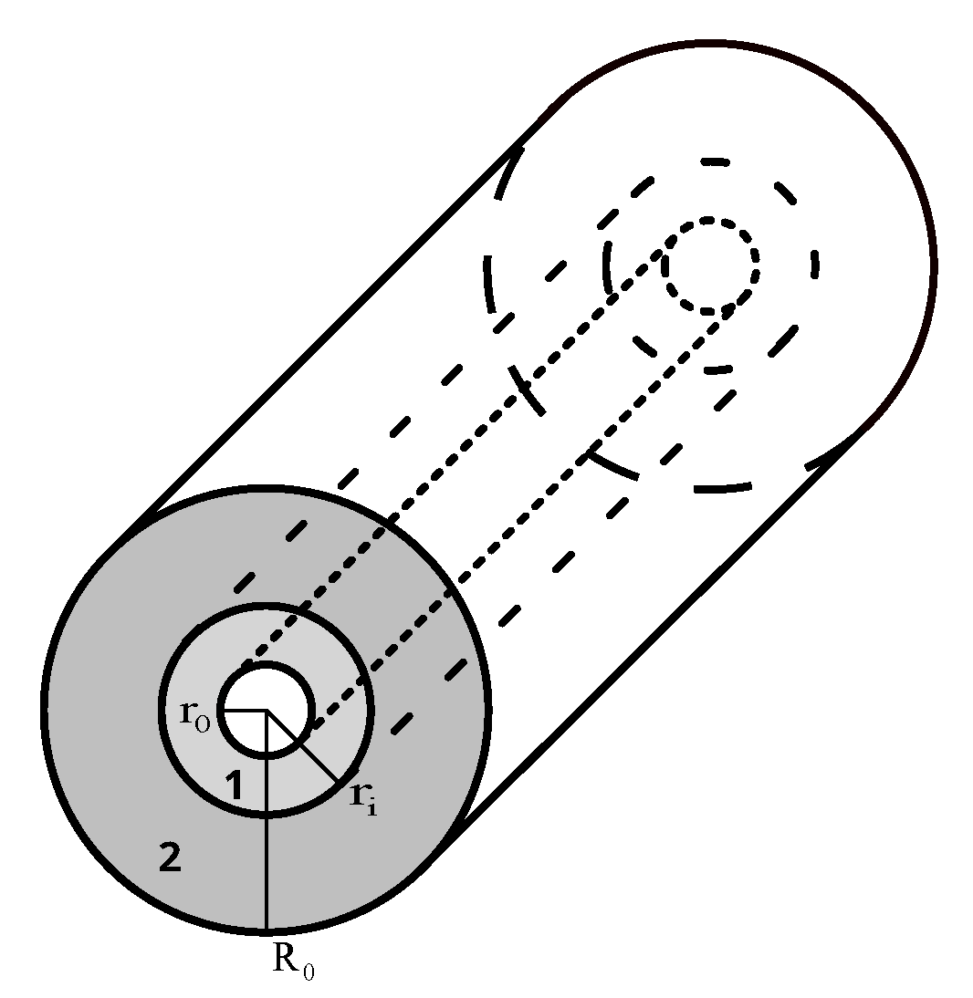
Figure 1. A two-layered hollow cylindrical tube. Layer 1: h 1 = r i r 0 , r 0 r r i and layer 2: h 2 = R 0 r i , r i r R 0 .
Symmetry 15 00685 g001
Figure 2. Young’s modulus dependence of tube CoF2–RbH2AsO4 on ρ 2 when ρ 1 = 2 .
Symmetry 15 00685 g002
Figure 3. Poisson’s ratio ν φ z for CsH2AsO4–FeGe2 (a) and FeGe2–RbH2AsO4 (b) at equal thicknesses of layers.
Symmetry 15 00685 g003
Figure 4. Poisson’s ratio ν r z for tubes Ba2Si2TiO8, ( s E )–WSi2 (a) and CsH2AsO4–Ba2Si2TiO8, ( s E ) (b) with equal thicknesses of layers.
Symmetry 15 00685 g004
Figure 5. Poisson’s ratios ν φ z (a) and ν r z (b) for CsNiF3–RbH2AsO4 tube with equal thicknesses of layers.
Symmetry 15 00685 g005
Figure 6. Poisson’s ratio ν φ z for tubes CsNiF3–LuAsO4 (a) and LuAsO4–RbH2AsO4 (b) at equal thicknesses of layers.
Symmetry 15 00685 g006
Figure 7. Poisson’s ratio ν r z for tubes HgI2–RbH2AsO4 at equal thicknesses of layers.
Symmetry 15 00685 g007
Figure 8. Poisson’s ratios ν φ z (a) and ν r z (b) of tube FeGe2 with equal thicknesses of layers.
Symmetry 15 00685 g008
Figure 9. Poisson’s ratios ν φ z and ν r z for tube LuAsO4–FeGe2 (a) and CsNiF3–RbH2AsO4 (b) for ρ 1 = 2 and ρ 2 = 2 .
Symmetry 15 00685 g009
Table 1. Engineering constants (Young’s modulus E and Poisson’s ratios ν 12 , ν 13 ) of six-constant tetragonal crystals.
Material E , GPa ν 12 ν 13
Ba2Si2TiO8, sE1360.26−0.32
CsH2AsO451.50.010.03
CsNiF334.40.450.06
CoF250.30.640.15
CoPt1750.430.32
In-17 at% Pb20.40.330.45
In-10 at% Tl4.460.430.53
In-15 at% Tl3.760.500.46
FeGe2209−0.040.39
LuAsO4244−0.020.32
HgI224.4−0.110.80
Hg2I21.850.880.03
PdPb26770.380.35
RbH2AsO443.9−0.370.08
Sn23.60.760.10
TiO21470.590.13
WSi24030.250.11
ZrSiO43770.070.28
Zr2Ni46.30.760.15
Table 2. Values of Young’s modulus E t h and E v r for tubes with equal thicknesses and volumes of layers.
Tube ρ 1 E th , GPa E th / E max ( 1 , 2 ) E vr , GPa E vr / E max ( 1 , 2 )
Sn–RbH2AsO41.1151.51.1750.91.16
CoPt–FeGe21.112060.982050.98
PdPb2–Sn1.113370.503540.52
LuAsO4–Hg2I21.111200.491260.52
Sn–RbH2AsO4251.91.1849.01.12
Hg2I2–RbH2AsO4234.20.7829.80.68
RbH2AsO4–Hg2I2222.60.5227.30.62
LuAsO4–RbH2AsO421250.511490.61
FeGe2–LuAsO422330.952280.93
Sn–RbH2AsO41051.71.1848.01.09
CsNiF3–RbH2AsO41048.61.1146.51.06
In–15 at% Tl-Hg2I2103.761.003.610.96
LuAsO4–FeGe2102240.912330.95
Sn–FeGe2101680.801290.62
PdPb2–In-15 at% Tl101890.283400.50
Table 3. Values of Young’s modulus E, its ratio to the largest Young’s modulus of layers E max ( 1 , 2 ) = max ( E ( 1 ) , E ( 2 ) ) and corresponding thickness parameters ρ 1 , ρ 2 for two-layered tubes from six-constant tetragonal crystals.
Tube E , GPa E / E max ( 1 , 2 ) ρ 1 ρ 2
RbH2AsO4–Zr2Ni68.51.481.341.18
Zr2Ni–RbH2AsO467.91.471.011.01
HgI2–Sn31.01.271.151.09
Sn–HgI231.01.271.011.02
RbH2AsO4–CoF263.61.261.251.19
CoF2–RbH2AsO463.31.261.011.01
HgI2–Zr2Ni49.51.071.842
Zr2Ni–HgI247.51.0321.01
PdPb2–WSi26700.9921.01
TiO2–In-17 at% Pb1460.9921.01
RbH2AsO4–Hg2I243.30.9921.01
WSi2–FeGe23990.9921.01
ZrSiO4–CoPt3730.9921.01
ZrSiO4–TiO23730.9921.01
LuAsO4–Zr2Ni2420.9921.01
FeGe2–CoF22070.9921.01
WSi2–CoPt3980.9921.01
PdPb2–Hg2I26590.9721.01
PdPb2–In-15 at% Tl6590.9721.01
Table 4. Minimal values of two-layered tubes for Poisson’s ratio ν φ z and corresponding thickness parameters ρ 1 , ρ 2 and radial coordinate ξ .
Tube ν φ z ρ 1 ρ 2 ξ
In-15 at% Tl-RbH2AsO4 2.56 220.5
In-15 at% Tl–LuAsO4 1.77 220.5
In-15 at% Tl–FeGe2 1.61 220.5
HgI2–LuAsO4 1.03 220.5
FeGe2–RbH2AsO4 0.54 1.0121.0
WSi2–RbH2AsO4 0.46 1.0121.0
HgI2–Sn 0.45 21.010.5
FeGe2–LuAsO4 0.23 1.5520.65
Sn–LuAsO4 0.23 1.4920.67
CoF2–LuAsO4 0.19 1.3420.75
FeGe2–Hg2I2 0.17 21.010.5
CoF2–ZrSiO4 0.07 1.6220.62
Zr2Ni–CsH2AsO40.021.0121.45
CoPt–CsH2AsO40.031.0121.55
CsH2AsO4–Zr2Ni0.0421.010.61
CsH2AsO4–WSi20.0421.010.68
Table 5. Minimal values of two-layered tubes for Poisson’s ratio ν r z and corresponding thickness parameters ρ 1 , ρ 2 and radial coordinate ξ .
Tube ν rz ρ 1 ρ 2 ξ
PdPb2–FeGe2 1.20 221
TiO2–FeGe2 1.14 221
CoPt–FeGe2 1.02 221
CoF2–RbH2AsO4 0.50 221
TiO2–CsH2AsO4 0.27 1.7621
Zr2Ni–HgI2 0.21 1.9021
Sn–HgI2 0.08 221
RbH2AsO4–TiO20.011.2821
RbH2AsO4–HgI20.02220.78
RbH2AsO4–CsH2AsO40.031.0121.68
TiO2–WSi20.061.941.771
CoF2–WSi20.071.301.011
HgI2–FeGe20.13221.21
Disclaimer/Publisher’s Note: The statements, opinions and data contained in all publications are solely those of the individual author(s) and contributor(s) and not of MDPI and/or the editor(s). MDPI and/or the editor(s) disclaim responsibility for any injury to people or property resulting from any ideas, methods, instructions or products referred to in the content.