Article

Electron Microscopy Study of Structural Defects Formed in Additively Manufactured AlSi10Mg Alloy Processed by Equal Channel Angular Pressing

by
Przemysław Snopiński
Department of Engineering Materials and Biomaterials, Silesian University of Technology, 18A Konarskiego Street, 44-100 Gliwice, Poland
Symmetry 2023, 15(4), 860; https://doi.org/10.3390/sym15040860
Submission received: 27 February 2023 / Revised: 22 March 2023 / Accepted: 3 April 2023 / Published: 4 April 2023
(This article belongs to the Special Issue Materials Science and Symmetry)

Abstract

:
This study focused on electron microscopy studies of microstructural defects formed in an additively manufactured (AM) AlSi10Mg alloy as a result of post-deformation by equal channel angular pressing (ECAP), with the aim of elucidating the fundamental deformation mechanisms that govern the plasticity of both the aluminium matrix and the silicon phase. This article focused on the process of grain refinement, metastable phase transformations, and microstructural defects such as stacking faults or amorphous areas that severely disrupt the face-centred cubic (FCC) crystal lattice symmetry. The findings presented in this study imply that deformation twinning, phase transformation, and amorphization are not mutually exclusive modes of Si phase deformation. Both can occur at an ECAP temperature of 150 °C. At a deformation temperature of 100 °C, amorphization is the dominant deformation mode of the Si phase. It was also discovered that dislocation slip was the predominant deformation mode of Al matrix at 150 °C, while at 100 °C, additionally stacking faults were formed within the Al matrix. The present findings provide not only a fundamental understanding of the deformation micro-mechanism of the SLMed AlSi10Mg alloy but also open a new horizon for the development of the next generation of structural materials.

1. Introduction

Over the past decade, additive manufacturing (AM) emerged as a cutting-edge manufacturing paradigm that revolutionised the field of material design and digital fabrication. AM is characterized by a wide range of processable materials that allow for reduced manufacturing costs and times, and the production of extremely complex lightweight parts that were previously beyond the capabilities of subtractive processing [1]. Among the various AM technologies, selective laser melting (SLM) is the most promising technique. In SLM process, a spherical metal powder is scattered on a building platform and then melted by a laser beam along a fixed 2D route [2,3]. Due to several rapid melting and solidification processes that increase the number of nucleation sites, the resulting microstructure of SLM parts is finer than that of their cast counterparts [4]. It was revealed that the microstructure of SLM-processed alloys consists of sub-micrometre cells with dense dislocations [5], which are essentially metastable, making the 3D printed alloys heterostructured materials [6]. Despite intensive characterization to unravel the complex nature of these cellular structures, there is still a debate about their formation, the impact on mechanical properties, and strategies to control their evolution in order to develop microstructures with improved mechanical properties [7].
To date, most research focused on post-processing of LPBF parts via heat treatment [8] and hot isostatic pressing (HIP) [8]. However, heat or HIP-treated parts generally exhibit lower yield strengths than as-built parts [9], which is mainly due to the coarsening of the microstructure and spheroidisation of the cellular eutectic network [10]. Additionally, surface treatment post-processing were used to eliminate surface defects, and achieve microstructure refinement [11].
Other less common techniques that can significantly improve the mechanical properties of LPBF components are based on plastic deformation. In this context, Ma et al. [12] applied cold rolling to the Al-Mg-Sc-Zr alloy. They reported a yield strength of 573 MPa with an average grain size of 2.4 ± 1.3 μm. Since SLMed alloys have a distinct initial microstructure that can be further refined [13], researchers also examined the capability of post-processing SLMed Al–Si alloys by severe plastic deformation (SPD) [14,15]. The term “severe plastic deformation” refers to a group of metalworking processes in which metallic materials are subjected to extremely high strains, in order to obtain ultrafine grains (UFG) typically <500 nm in size or even grains in the nanometer range (NG), thereby significantly improving the materials’ properties such as yield strength, wear, and corrosion behaviour [16,17,18]. These processes include high pressure torsion (HPT) [19], accumulative roll bonding (ARB) [20], twist extrusion (TE) [21], equal channel angular pressing (ECAP) [22], and many others [23,24,25]. Among the mentioned processes, ECAP is one of the most popular SPD because it produces a significant level of grain refinement [26], and generates large shear strains within a well-defined deformation zone in the angular ECAP die [27].
The SPD post-processing applied to the SLM parts allowed both higher strength and improved ductility in the metals/alloys studied. This is due to the fact that the pre-existing dislocation networks at the cell boundaries improve the material property by acting as barriers (slowing down the dislocation motion) for newly generated dislocations during plastic deformation [28]. Moreover, the heterogeneity of solutes in SLM-fabricated Al–Si alloys can affect the deformation mechanism; therefore, they are drastically different from those of conventionally manufactured alloys. Unfortunately, little attention was paid to the study of deformation mechanisms and defects such as dislocations, grain boundaries, stacking faults, or twins, which obviously contribute significantly to the improvement of mechanical strength. In addition, not much attention was paid to the deformation behaviour of the Si phase in SLMed-Al–Si alloys post-processed by SPD; therefore, there is a significant knowledge gap regarding this phenomenon.
This study was motivated by previous discoveries of the author [18,29] on SPD post-processing of SLMed Al–Si alloys, and aims to expand future application of a hybrid manufacturing variant combining low-temperature annealing and SPD post-processing aimed to improve mechanical properties of the alloy. This article provides experimental data on the microstructure, which can then be used to establish the relationship between the microstructure and the mechanical properties, and to develop novel post-processing techniques based on plastic deformation.

2. Methodology

A gas-atomised powder with a composition of Al-10.81Si-0.55Mg-0.15Ti-0.15 Cu-0.09Fe (wt%) was used for the SLM process. For high-density and crack-free samples, the ideal printing settings were as follows.
  • Laser power: 175 W;
  • Scan speed: 1.4 m/s;
  • Layer thickness: 20 µm.
After the 3D printing process, to increase the technological plasticity and to modify the unique cellular microstructure, the samples were annealed with the following scheme:
  • Low-temperature annealing at 280 °C for 9 min (sample designation–HT280);
  • Low-temperature annealing at 320 °C for 9 min (sample designation HT320).
The specimens were then machined to fit into an ECAP tool’s 14.75 × 14.75 mm rectangular mould. Before deformation, they were preheated at the deformation temperature and held at that temperature for 5 min.
The preheated specimens were lubricated with a molybdenum-based lubricant (MoS2) and then, immediately inserted into the ECAP mould having a channel angle of 90° and a corner angle of 20°. The 3D-printed samples were subjected to an ECAP pass at 100 °C (HT320E100) and at 150 °C (HT280E150).
Microstructural studies were performed by analysing secondary electron microscopy (SEM), transmission electron microscopy (TEM), high-resolution transmission electron images (HRTEM), and selected area electron diffraction patterns (SAED) acquired with Zeiss Supra 35 and S/TEM TITAN 80–300 microscopes. For TEM studies, focused ion beam (FIB) cut lamellae extracted along the extrusion direction (ED) were used. Transmission electron microscopy (TEM) images were further analysed using Digital Micrograph (Gatan Inc. version 2.32.888.0, United States) and CrysTBox (Crystallographic Toolbox, Institute of Physics Academy of Sciences of the Czech Republic, gpaGUI 0.01) software.

3. Results

3.1. Effect of Heat Treatment and Plastic Deformation on the Cellular Microstructure

Figure 1 presents the SEM micrographs of the AlSi10Mg alloy in as-build and heat-treated states. As shown, heat treatment significantly changed the unique cellular microstructure of the AlSi10Mg alloy. After low-temperature annealing, the HT320 sample exhibited a coarser Si network and there were more dot-like precipitates within the α-Al cells. On the other hand, the HT280 sample exhibited a thinner and more continuous Si network. Based on this study [30], it can be concluded that by modifying the cellular microstructure, we can influence the constraint of the Si phase. With a more resolved microstructure, more dislocations penetrate the cellular region during plastic deformation, leading to a decrease in strain incompatibility between the Al/Si phases, and finally, fewer geometrically necessary dislocations (GNDs) and statistically stored dislocations (SSDs) accumulate near this interface during plastic deformation.
Figure 2 shows the SEM micrographs of the heat-treated specimens subjected to ECAP processing. As can be seen, partial spheroidisation of the eutectic Si network occurred in both samples. However, from a direct comparison of Figure 2a,b, it can be concluded that a higher deformation temperature leads to a stronger fracture and globularization of the Si network, since sample HT280E150 had a thicker Si boundary network.

3.2. Submicrometric Microstructure Analysis

3.2.1. Sample HT280E150

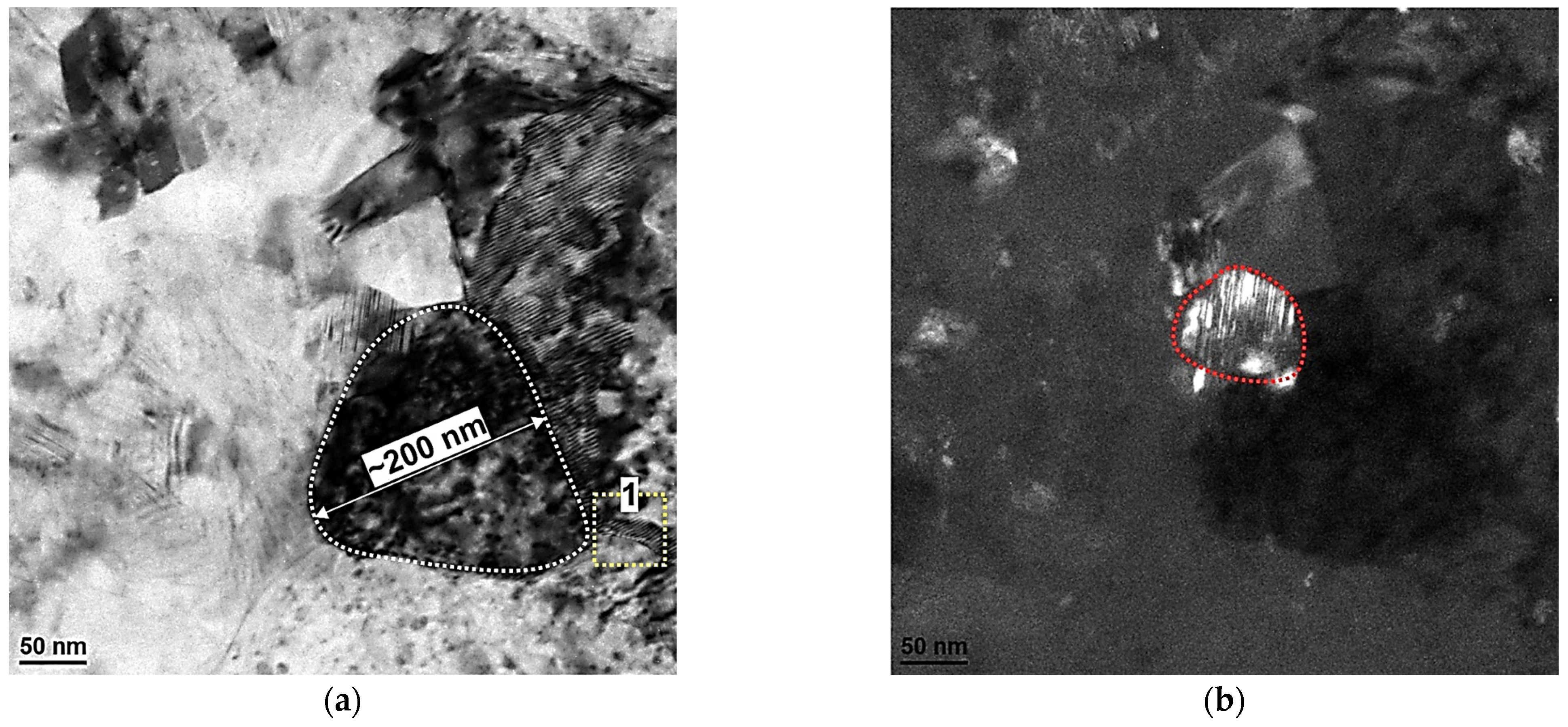
Figure 3a,b shows the subgrain microstructure of the sample HT280E150. Bright-field and dark-field TEM images revealed significant refinement of the microstructure as a result of ECAP processing at 150 °C. Several equiaxed subgrains with diameters of about 200 nm can be seen, as well as dislocation structures formed to reduce the total energy of the deformed crystal. In addition, TEM images revealed a considerable number of twins formed within the round Si particle with a diameter of about 50 nm (see the red outline in Figure 3b).
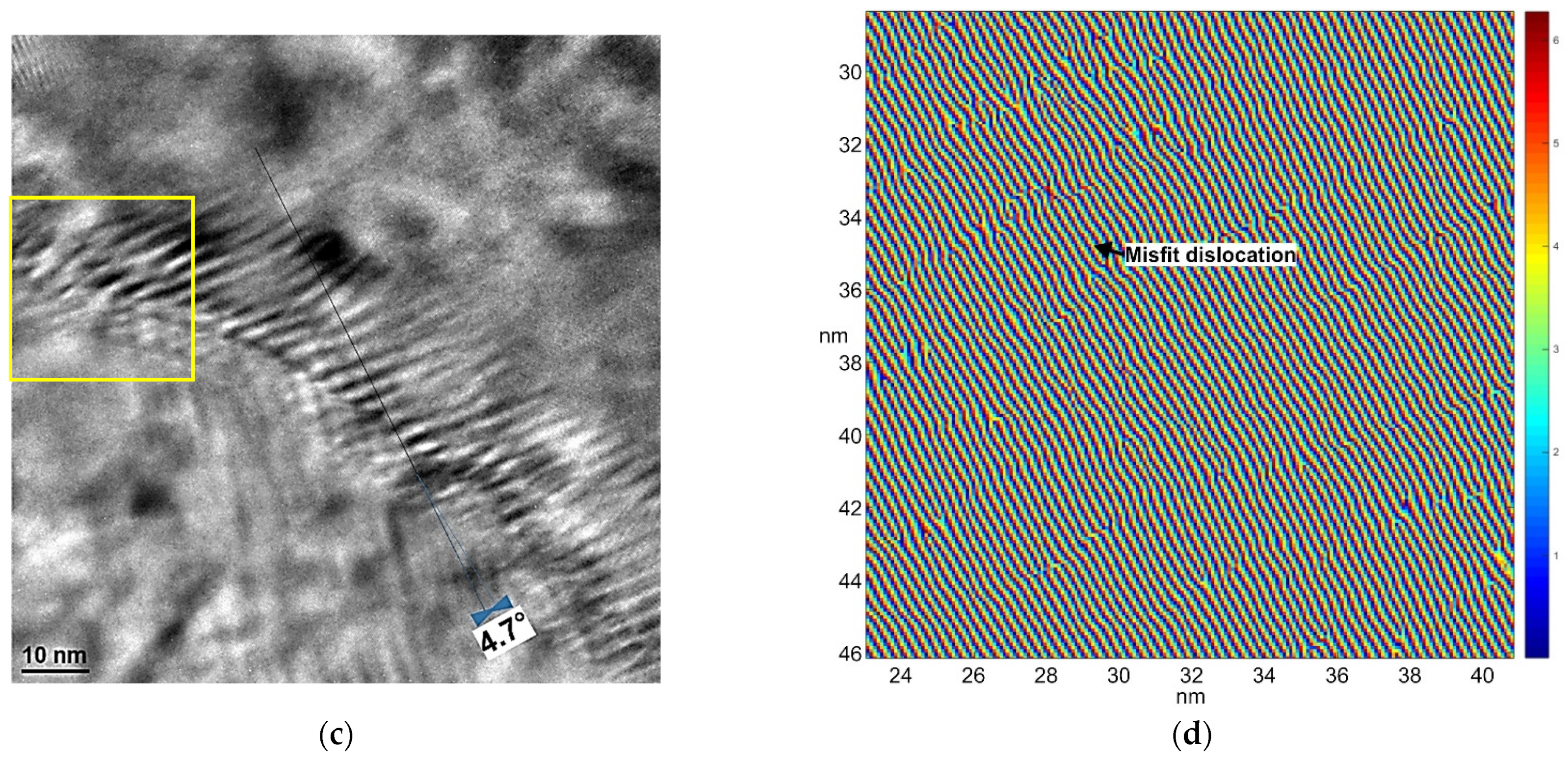
Figure 3c shows a closer view of the yellow box highlighted in Figure 3a. To reveal more details about the atomic arrangement in this region, high-resolution imaging was used. The HRTEM image uncovers a subgrain boundary with an estimated misorientation angle of approximately 4.7°. Furthermore, the geometric phase analysis (Figure 3d) showed that this boundary contained a high density of lattice dislocations typical of LAGBs [31].

3.2.2. Sample HT320E100

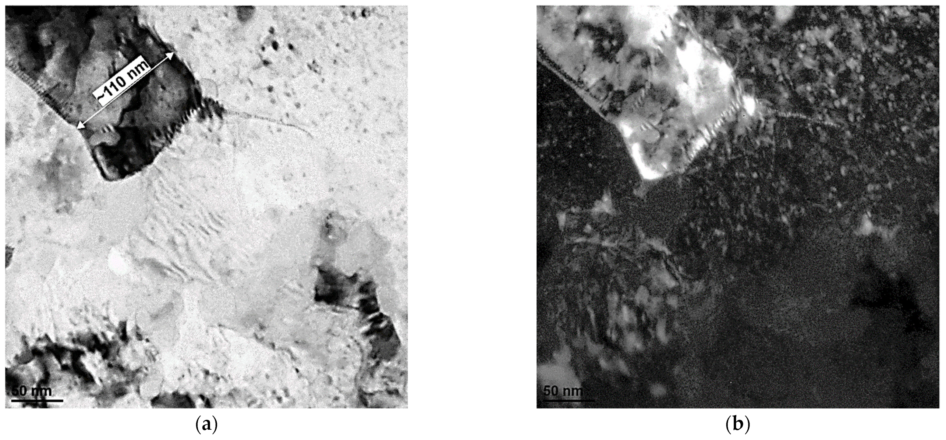
Figure 4 shows representative TEM images of the subgrain structure of the HT320E100 sample. ECAP processing at lower temperatures resulted in a finer structure consisting of subgrains around 100 nm in size. In addition, the development of microcrystallites with a high dislocation density can also be seen in the dark-field TEM image, see Figure 4b.
Pairs of bright-field (BF) and dark-field (DF) TEM images acquired inside the α-Al cell showed needle-shaped precipitates/intermetallics ranging from 30 to 80 nm in length and of several nanometres in width (Figure 4c,d). Their presence in the aluminium matrix indicated that some amount of Si was precipitated from the supersaturated solid solution during heat treatment at 320 °C and subsequent ECAP processing. It is worth noting that such precipitates, together with the Si network, could act as effective strengthening agents and increase the overall yield strength of the alloy.
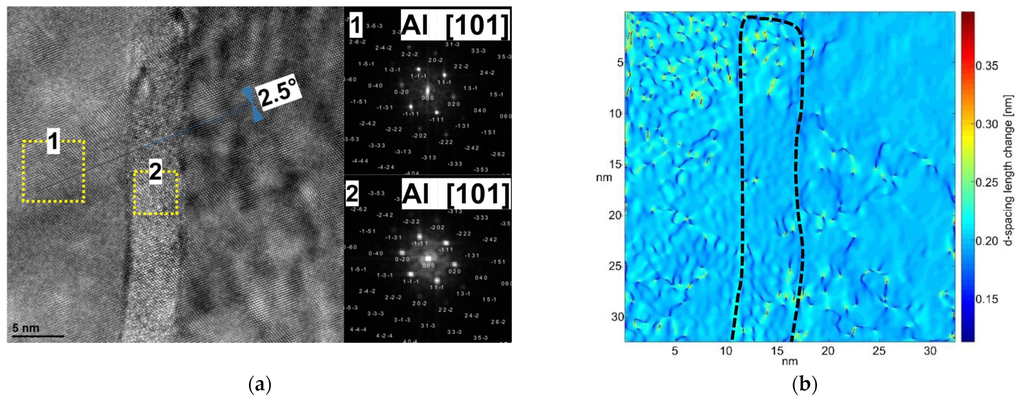
According to the high-resolution transmission microscopy image (Figure 5a), the needle-shaped precipitates were completely coherent and had the same crystal structure as the matrix. Moreover, their presence caused a lattice distortion that lead to the formation of an extremely low subgrain boundary (with a measured misorientation angle of about 2.5°).
Geometric phase analysis (Figure 5b) of the local distribution of d-spacings between the (111) crystal planes showed that there was a deviation from the expected inter-plane spacing of 0.233 nm (for aluminium) within the needle-shaped precipitate, suggesting that this region may have been enriched in Si. This image also showed several dislocation cores that compensated the lattice mismatch between the subgrain boundaries (see dark blue spots) and residual stresses within the aluminium matrix in the crystallographic direction.

3.3. Plastic Deformation Modes of the Si Phase at 150 °C

According to these studies [32,33,34,35], the main deformation modes of the silicone phase are twinning, phase transformation, and amorphization. In this section, these deformation modes were analysed in terms of the ECAP processing temperature.
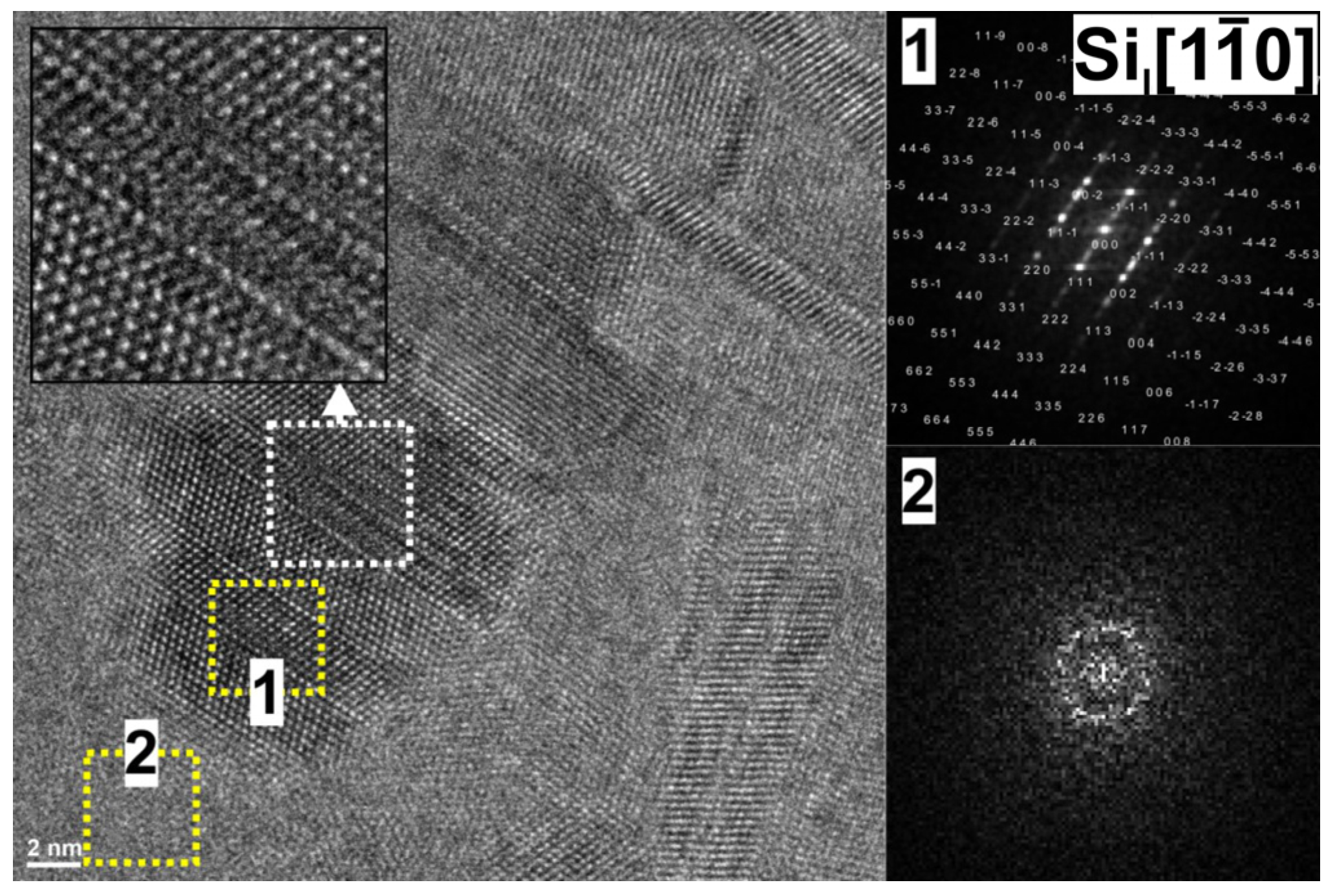
Figure 6 shows the HRTEM image of the Si crystallites in the microstructure of sample HT280E150. As can be seen, a considerable number of deformation twins and stacking faults that ran along the 111 planes were formed within this precipitate. According to the fast Fourier transform (FFT), this is a diamond cubic (Si-I) phase. It can be conjectured that the deformation twins formed as a result of the increased stresses originating from the piled-up dislocations at the Al/Si interface (stress inhomogeneity accumulation at phase boundaries). This observation is in agreement with the study of Kiran et al. [36], who found that the deformation by twinning dominates in the Si phase at 150 °C and 200 °C.
It can also be seen that this crystalline Si-I phase precipitate was embedded in an amorphous layer, as evidenced by the FFT with halo rings. This implies that an amorphous phase may originate from the surface, grain boundary, or interphase boundary as a result of high dislocation accumulation.
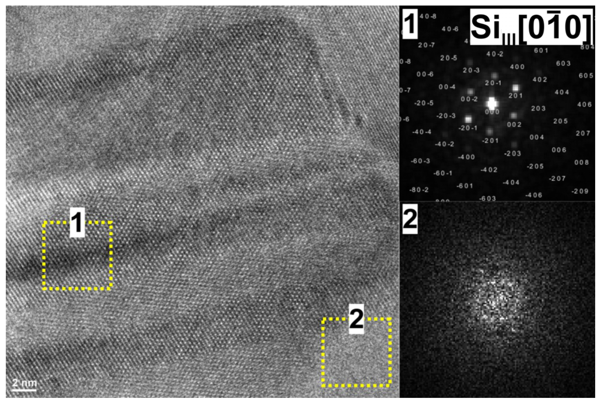
Figure 7 shows the HRTEM image of another silicone crystallite found in the microstructure of sample HT280E150. According to the fast Fourier transform (FFT), it was a Si-III phase embedded in an amorphous Si layer. The presence of the Si-III phase suggests that one of the deformation modes of the Si phase in the LPBF AlSi10Mg alloy could be phase transformation.
According to this study [34], the phase transformation can occur via two routes: (1) Si-I → α-Si → Si-XII in α-Si or (2) (i.e., Si-I → Si-II → Si-III/Si-XII or α-Si). In the following study [37], that the phase transformation Si-I Si-II required phase stresses of about 9–16 GPa, while the Si-III formed upon pressure relief. Considering that Si behaves elastically up to ∼10 GPa [38], and the observation of twin deformations in the Si-I phase (Figure 6), it can be concluded that the local phase stresses resulting from the dislocation accumulation could be high enough to cause the phase transformation that was experimentally demonstrated in this article. It can be speculated that the Si-III phase formed from the thermodynamically unstable Si-II phase during stress relief (after deformation). In this type of phase transformation, pressure is the main driving force, while temperature can overcome the activation barrier for phase transformation. In general, the results presented in this subsection indicate that the twinning, phase transformation, and amorphization phases are the preferred deformation mechanism of the Si phase when the alloy is deformed at 150 °C.

3.4. Plastic Deformation Modes of the Si Phase at 100 °C

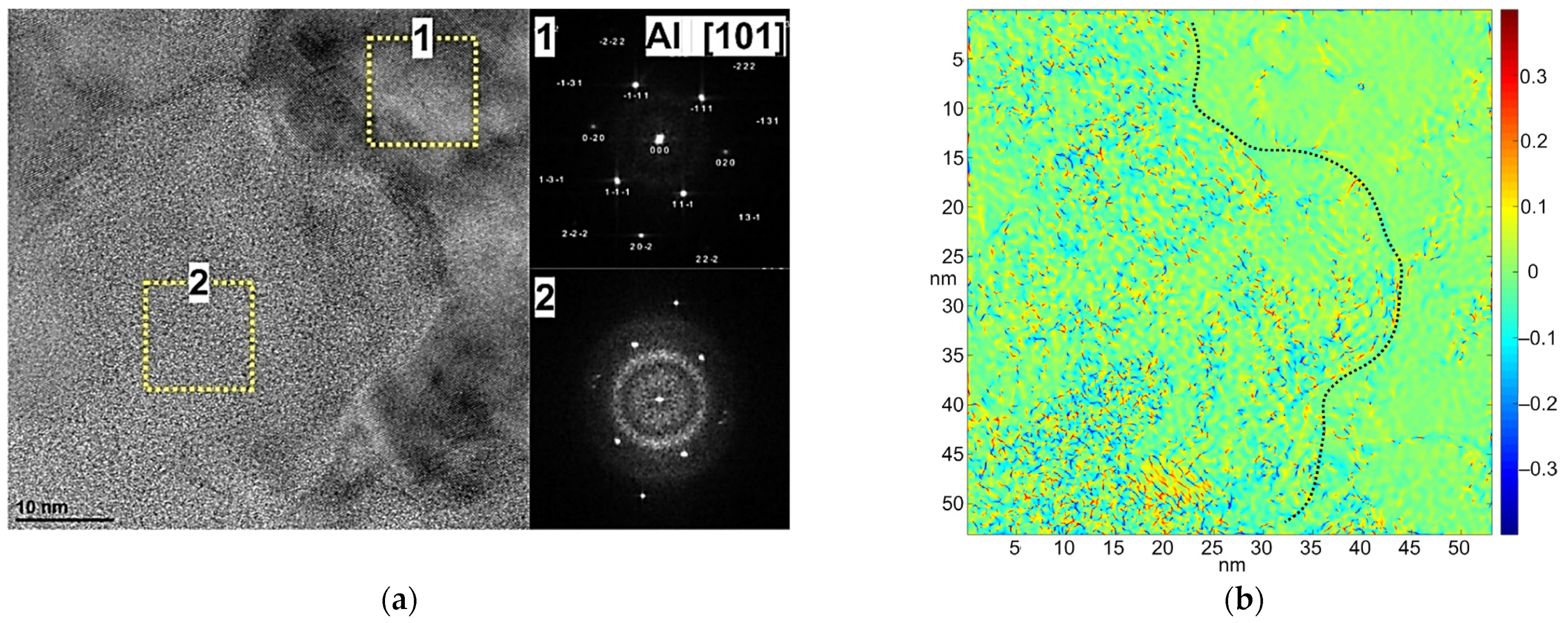
Figure 8 shows the HRTEM image of the eutectic Al/Si zone in sample HT320E100. The diffractograms obtained by fast Fourier transform corresponding to the yellow boxes confirmed the presence of the crystalline aluminium phase as well as the Si phase in amorphous form. Interestingly, in sample HT320E100, the silicon phase was found only in the form of interconnected non-crystalline islands. Therefore, it can be assumed that when the alloy was deformed at lower temperatures, more dislocations accumulated near the Al/Si interfaces, and when the dislocation density in the interface region reached a critical level, amorphization of the Si phase occurred. The geometric phase analysis in Figure 8a shows that the local shear stress in the amorphous region was much higher than that in the surrounding region (Figure 8b), indicating that the shear stress plays a crucial role in the amorphization. It can be concluded that the amorphization was initiated at the highly distorted, symmetry-breaking dislocation cores.
It is worth noting that the amorphous regions can exhibit excellent mechanical properties [39,40] and provide additional strengthening and/or toughening mechanisms that enhance the ability of the alloy to withstand extreme loading conditions.
Large deviatoric stresses generated at the intersections of defects (dislocations, stacking faults, and twins) or transformation packages can be released during the amorphization process. Furthermore, this release of stress concentrations prevents the formation of nanoscale fractures. In addition, since dislocations cannot propagate in the amorphous phase, it should be tougher than the crystalline phase, therefore leading to the material strengthening.
Following the work of Chen [41], the amorphization process started around the dislocation core regions and was initiated when the resolved shear stress exceeded the value of (8.6–9.3 GPa). On the other hand, it was also reported that in the case of a high accumulation [42] and large plastic shear [43], the critical shear stress required for amorphization can be much lower ~1.6 GPa. According to Jiapeng et al. [34] the amorphous Si forms directly from the cubic diamond Si or upon pressure release from the Si-II phase with a high rate of pressure relief [44]. The TEM microstructural analyses in this article showed the existence of amorphous Si in both samples. However, three different forms of Si phases were found only in sample HT280E150 (deformed at 150 °C). Therefore, it can be assumed that a lower deformation temperature prevents the long-distance migration of the elemental point defects introduced by ECAP processing; thus, at a higher deformation temperature, a larger accumulation may be required to initiate the direct transformation from the crystalline state to the amorphous state. In this case, observing the different crystalline phases together with an amorphous Si phase in the deformed region seems quite reasonable. On the other hand, if the sample is deformed at a lower temperature (100 °C), more dislocations accumulate at the Al/Si interface, leading to a larger step and a corresponding stress concentration; therefore, the higher accumulation leads directly to the phase transformation Si-I -> a-Si.

3.5. Aluminium Phase Deformation Mode

Plastic deformation in materials with face-centred cubic crystal structure (FCC) is caused by dislocation slip, mainly by the octahedral {1 1 1} < 1 1 0 > slip systems [45]. The thorough microstructural investigations in this article confirmed the enormous dislocation activity and its further accumulation (see Figure 3).
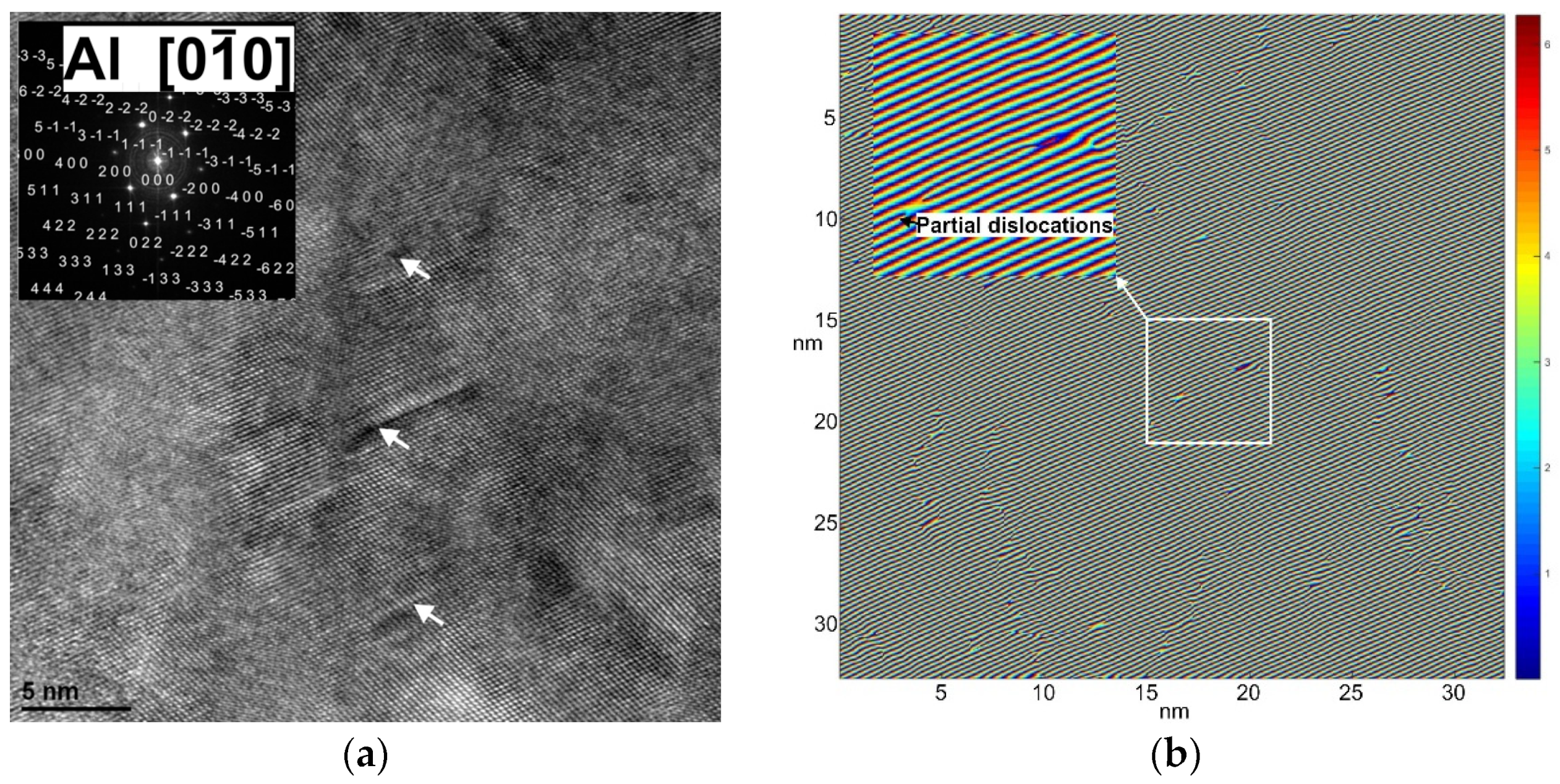
Microstructural examination in high-resolution mode revealed several planar defects (stacking faults (SFs)) formed within the aluminium matrix (see white arrows in Figure 9a). These SFs, which disrupt the ABCABC stacking sequence and the local lattice symmetry, were found only in sample HT320E100. Partial dislocations originating from the Al/Si interface regions are believed to promote the formation of stacking faults or “nanotwins” in the studied alloy. In an aluminium matrix, they can be formed when the grain size is very small—close to a critical value. Under such conditions, the activation of partial dislocations is easier than that of lattice dislocations [46]. It is also speculated that deformation incompatibility could lead to an increase in interfacial shear stress, resulting in a decrease in effective stacking fault energy, so that SFs form in the aluminium matrix [47]. This implies that both the nanocrystalline and heterogeneous microstructure in the HT320E100 sample might have favoured the formation of nanotwins/stacking faults within the aluminium phase.
Other symmetry breaking defects (generating lattice stresses) formed in the aluminium matrix are evaluated using the geometric phase analysis of the HRTEM image shown in Figure 9a. Based on the GPA analysis (Figure 9b), the defective structures (Figure 10) can be classified into different types, which are described as follows:
  • Defect (ii) is a single Y-like edge dislocation caused by the slippage of the atomic plane by half a layer;
  • The defects (i) and (iv) consist of a pair of (ii) defects with opposite Burgers vector interacting at a certain distance. Such a configuration is advantageous to reduce the total stress energy;
  • Defect (iii) is a single strain region extending over a relatively large area (more than 3–4 layers), where the lattice displacement is less than half of the interlayer.
Figure 10. Lattice defects formed within an aluminium matrix as a result of ECAP processing (from Figure 9b). Figure shows the result of GPA analysis of lattice defects formed in an aluminium matrix near stacking faults.
Symmetry 15 00860 g010
At this point, it should be noted that Figure 10 shows the magnified view of the defects formed within the area shown in Figure 9b.

4. Conclusions

In this work, transmission electron microscopy was used to analyse the microstructural evolution of the SLM AlSi10Mg alloy processed by equal channel angular pressing. It was found that:
  • The ECAP processing of additively manufactured AlSi10Mg alloy resulted in a very fine-grained microstructure sizes in the range of 0.1–0.2 µm. The refined microstructure consisted of dislocation arrays.
  • During ECAP processing, the dislocation slip was the dominant mechanism of the aluminium matrix in both investigated samples.
  • Partial dislocation-associated stacking faults formation was an additional deformation mechanism of the sample deformed at 100 °C.
  • The phase transformation of diamond cubic Si phase was a dominant deformation mode at higher deformation temperature (ECAP at 150 °C); whereas, at lower deformation temperature (ECAP at 100 °C), only amorphous Si phase was formed.
  • All of the deformation mechanisms shown could inhibit the initiation and propagation of cracks and significantly affect the ductility of an alloy. Materials scientists should incorporate these mechanisms when designing novel post-processing methods to accurately design the properties of SLMed Al–Si alloys.

Funding

The research was funded by the National Science Centre, Poland based on the decision number 2021/43/D/ST8/01946.

Data Availability Statement

The data presented in this study are available on request from the corresponding author.

Conflicts of Interest

The author declares no conflict of interests.

References

  1. Kurian, S.; Mirzaeifar, R. Deformation mechanisms of the subgranular cellular structures in selective laser melted 316L stainless steel. Mech. Mater. 2020, 148, 103478. [Google Scholar] [CrossRef]
  2. Pilgar, C.M.; Fernandez, A.M.; Lucarini, S.; Segurado, J. Effect of printing direction and thickness on the mechanical behavior of SLM fabricated Hastelloy-X. Int. J. Plast. 2022, 153, 103250. [Google Scholar] [CrossRef]
  3. Limbasiya, N.; Jain, A.; Soni, H.; Wankhede, V.; Krolczyk, G.; Sahlot, P. A comprehensive review on the effect of process parameters and post-process treatments on microstructure and mechanical properties of selective laser melting of AlSi10Mg. J. Mater. Res. Technol. 2022, 21, 1141–1176. [Google Scholar] [CrossRef]
  4. Cai, X.; Liu, T.; Yan, X.; Cheng, Z.; Pan, L.; Tian, Z.; Luo, L.; Su, Y. Effect of process parameters on microstructures and properties of Al–42Si alloy fabricated by selective laser melting. Heliyon 2022, 8, e09680. [Google Scholar] [CrossRef]
  5. Kong, D.; Dong, C.; Wei, S.; Ni, X.; Zhang, L.; Li, R.; Wang, L.; Man, C.; Li, X. About metastable cellular structure in additively manufactured austenitic stainless steels. Addit. Manuf. 2021, 38, 101804. [Google Scholar] [CrossRef]
  6. Liu, Y.; Sun, J.; Fu, Y.; Xu, B.; Li, B.; Xu, S.; Huang, P.; Cheng, J.; Han, Y.; Han, J.; et al. Tuning strength-ductility combination on selective laser melted 316L stainless steel through gradient heterogeneous structure. Addit. Manuf. 2021, 48, 102373. [Google Scholar] [CrossRef]
  7. Mohd Yusuf, S.; Chen, Y.; Yang, S.; Gao, N. Microstructural evolution and strengthening of selective laser melted 316L stainless steel processed by high-pressure torsion. Mater. Charact. 2020, 159, 110012. [Google Scholar] [CrossRef]
  8. Hirata, T.; Kimura, T.; Nakamoto, T. Effects of hot isostatic pressing and internal porosity on the performance of selective laser melted AlSi10Mg alloys. Mater. Sci. Eng. A 2020, 772, 138713. [Google Scholar] [CrossRef]
  9. Zhang, H.; Li, C.; Yao, G.; Zhang, Y. Hot isostatic pressing of laser powder-bed-fused 304L stainless steel under different temperatures. Int. J. Mech. Sci. 2022, 226, 107413. [Google Scholar] [CrossRef]
  10. Zhong, Y.; Liu, L.; Wikman, S.; Cui, D.; Shen, Z. Intragranular cellular segregation network structure strengthening 316L stainless steel prepared by selective laser melting. J. Nucl. Mater. 2016, 470, 170–178. [Google Scholar] [CrossRef]
  11. Maamoun, A.; Elbestawi, M.; Veldhuis, S. Influence of Shot Peening on AlSi10Mg Parts Fabricated by Additive Manufacturing. J. Manuf. Mater. Process. 2018, 2, 40. [Google Scholar] [CrossRef] [Green Version]
  12. Ma, R.; Peng, C.; Cai, Z.; Wang, R.; Zhou, Z.; Li, X.; Cao, X. Enhanced strength of the selective laser melted Al-Mg-Sc-Zr alloy by cold rolling. Mater. Sci. Eng. A 2020, 775, 138975. [Google Scholar] [CrossRef]
  13. Hosseinzadeh, A.; Radi, A.; Richter, J.; Wegener, T.; Sajadifar, S.V.; Niendorf, T.; Yapici, G.G. Severe plastic deformation as a processing tool for strengthening of additive manufactured alloys. J. Manuf. Process. 2021, 68, 788–795. [Google Scholar] [CrossRef]
  14. Mohd Yusuf, S.; Nie, M.; Chen, Y.; Yang, S.; Gao, N. Microstructure and corrosion performance of 316L stainless steel fabricated by Selective Laser Melting and processed through high-pressure torsion. J. Alloys Compd. 2018, 763, 360–375. [Google Scholar] [CrossRef]
  15. Yusuf, S.M.; Hoegden, M.; Gao, N. Effect of sample orientation on the microstructure and microhardness of additively manufactured AlSi10Mg processed by high-pressure torsion. Int. J. Adv. Manuf. Technol. 2020, 106, 4321–4337. [Google Scholar] [CrossRef] [Green Version]
  16. Langdon, T.G. The principles of grain refinement in equal-channel angular pressing. Mater. Sci. Eng. A 2007, 462, 3–11. [Google Scholar] [CrossRef]
  17. Snopiński, P.; Tański, T.; Gołombek, K.; Rusz, S.; Hilser, O.; Donič, T.; Nuckowski, P.M.; Benedyk, M. Strengthening of AA5754 Aluminum Alloy by DRECE Process Followed by Annealing Response Investigation. Materials 2020, 13, 301. [Google Scholar] [CrossRef] [Green Version]
  18. Snopiński, P.; Woźniak, A.; Pagáč, M. Microstructural Evolution, Hardness, and Strengthening Mechanisms in SLM AlSi10Mg Alloy Subjected to Equal-Channel Angular Pressing (ECAP). Materials 2021, 14, 7598. [Google Scholar] [CrossRef]
  19. Liu, M.; Roven, H.J.; Liu, X.; Murashkin, M.; Valiev, R.Z.; Ungár, T.; Balogh, L. Grain refinement in nanostructured Al-Mg alloys subjected to high pressure torsion. J. Mater. Sci. 2010, 45, 4659–4664. [Google Scholar] [CrossRef]
  20. Reza Toroghinejad, M.; Ashrafizadeh, F.; Jamaati, R. On the use of accumulative roll bonding process to develop nanostructured aluminum alloy 5083. Mater. Sci. Eng. A 2013, 561, 145–151. [Google Scholar] [CrossRef]
  21. Orlov, D.; Beygelzimer, Y.; Synkov, S.; Varyukhin, V.; Tsuji, N.; Horita, Z. Plastic flow, structure and mechanical properties in pure Al deformed by twist extrusion. Mater. Sci. Eng. A 2009, 519, 105–111. [Google Scholar] [CrossRef]
  22. Saxl, I.; Kalousová, A.; Ilucová, L.; Sklenička, V. Grain and subgrain boundaries in ultrafine-grained materials. Mater. Charact. 2009, 60, 1163–1167. [Google Scholar] [CrossRef]
  23. Ebrahimi, M.; Wang, Q.; Attarilar, S. A comprehensive review of magnesium-based alloys and composites processed by cyclic extrusion compression and the related techniques. Prog. Mater. Sci. 2023, 131, 101016. [Google Scholar] [CrossRef]
  24. Song, X.; Wang, L.; Wang, R.; Liu, Y. Effects of annealing on microstructure evolution and mechanical properties of constrained groove pressed pure titanium. Mater. Sci. Eng. A 2022, 831, 142245. [Google Scholar] [CrossRef]
  25. Zhang, L.; Ren, R.; Ren, J.; Liu, Y.; Liao, W.; Li, T.; Liu, C.; Wang, Q. Effects of cyclic closed-die forging on the microstructural evolution and mechanical properties of SiC/AZ91D nanocomposites. Int. J. Mod. Phys. B 2022, 36, 2240066. [Google Scholar] [CrossRef]
  26. Tang, L.; Peng, X.; Huang, J.; Ma, A.; Deng, Y.; Xu, G. Microstructure and mechanical properties of severely deformed Al-Mg-Sc-Zr alloy and their evolution during annealing. Mater. Sci. Eng. A 2019, 754, 295–308. [Google Scholar] [CrossRef]
  27. Frint, P.; Wagner, M.F.-X. Strain partitioning by recurrent shear localization during equal-channel angular pressing of an AA6060 aluminum alloy. Acta Mater. 2019, 176, 306–317. [Google Scholar] [CrossRef]
  28. Park, J.M.; Asghari-Rad, P.; Zargaran, A.; Bae, J.W.; Moon, J.; Kwon, H.; Choe, J.; Yang, S.; Yu, J.-H.; Kim, H.S. Nano-scale heterogeneity-driven metastability engineering in ferrous medium-entropy alloy induced by additive manufacturing. Acta Mater. 2021, 221, 117426. [Google Scholar] [CrossRef]
  29. Snopiński, P.; Matus, K.; Tatiček, F.; Rusz, S. Overcoming the strength-ductility trade-off in additively manufactured AlSi10Mg alloy by ECAP processing. J. Alloys Compd. 2022, 918, 165817. [Google Scholar] [CrossRef]
  30. Li, Z.; Li, Z.; Tan, Z.; Xiong, D.B.; Guo, Q. Stress relaxation and the cellular structure-dependence of plastic deformation in additively manufactured AlSi10Mg alloys. Int. J. Plast. 2020, 127, 102640. [Google Scholar] [CrossRef]
  31. Zhang, Z.; Ódor, É.; Farkas, D.; Jóni, B.; Ribárik, G.; Tichy, G.; Nandam, S.-H.; Ivanisenko, J.; Preuss, M.; Ungár, T. Dislocations in Grain Boundary Regions: The Origin of Heterogeneous Microstrains in Nanocrystalline Materials. Metall. Mater. Trans. A 2020, 51, 513–530. [Google Scholar] [CrossRef] [Green Version]
  32. Gerberich, W.W.; Mook, W.M.; Cordill, M.J.; Carter, C.B.; Perrey, C.R.; Heberlein, J.V.; Girshick, S.L. Reverse plasticity in single crystal silicon nanospheres. Int. J. Plast. 2005, 21, 2391–2405. [Google Scholar] [CrossRef]
  33. Fang, Q.; Zhang, L. Emission of partial dislocations in silicon under nanoindentation. J. Mater. Res. 2013, 28, 1995–2003. [Google Scholar] [CrossRef]
  34. Jiapeng, S.; Cheng, L.; Han, J.; Ma, A.; Fang, L. Nanoindentation Induced Deformation and Pop-in Events in a Silicon Crystal: Molecular Dynamics Simulation and Experiment. Sci. Rep. 2017, 7, 10282. [Google Scholar] [CrossRef]
  35. Huang, J.Y.; Yasuda, H.; Mori, H. Deformation-induced amorphization in ball-milled silicon. Philos. Mag. Lett. 1999, 79, 305–314. [Google Scholar] [CrossRef]
  36. Kiran, M.S.R.N.; Tran, T.T.; Smillie, L.A.; Haberl, B.; Subianto, D.; Williams, J.S.; Bradby, J.E. Temperature-dependent mechanical deformation of silicon at the nanoscale: Phase transformation versus defect propagation. J. Appl. Phys. 2015, 117, 205901. [Google Scholar] [CrossRef] [Green Version]
  37. Crain, J.; Ackland, G.J.; Maclean, J.R.; Piltz, R.O.; Hatton, P.D.; Pawley, G.S. Reversible pressure-induced structural transitions between metastable phases of silicon. Phys. Rev. B 1994, 50, 13043–13046. [Google Scholar] [CrossRef]
  38. Zhao, S.; Hahn, E.N.; Kad, B.; Remington, B.A.; Wehrenberg, C.E.; Bringa, E.M.; Meyers, M.A. Amorphization and nanocrystallization of silicon under shock compression. Acta Mater. 2016, 103, 519–533. [Google Scholar] [CrossRef] [Green Version]
  39. Follstaedt, D.M.; Knapp, J.A.; Myers, S.M. Mechanical properties of ion-implanted amorphous silicon. J. Mater. Res. 2004, 19, 33. [Google Scholar] [CrossRef]
  40. Kulikovsky, V.; Vorlíček, V.; Boháč, P.; Stranyánek, M.; Čtvrtlík, R.; Kurdyumov, A. Mechanical properties of amorphous and microcrystalline silicon films. Thin Solid Film. 2008, 516, 5368–5375. [Google Scholar] [CrossRef]
  41. Chen, H.; Levitas, V.I.; Xiong, L. Amorphization induced by 60° shuffle dislocation pileup against different grain boundaries in silicon bicrystal under shear. Acta Mater. 2019, 179, 287–295. [Google Scholar] [CrossRef]
  42. McBride, E.E.; Krygier, A.; Ehnes, A.; Galtier, E.; Harmand, M.; Konôpková, Z.; Lee, H.J.; Liermann, H.-P.; Nagler, B.; Pelka, A.; et al. Phase transition lowering in dynamically compressed silicon. Nat. Phys. 2019, 15, 89–94. [Google Scholar] [CrossRef] [Green Version]
  43. Gao, Y.; Ma, Y.; An, Q.; Levitas, V.; Zhang, Y.; Feng, B.; Chaudhuri, J.; Goddard, W.A. Shear driven formation of nano-diamonds at sub-gigapascals and 300 K. Carbon 2019, 146, 364–368. [Google Scholar] [CrossRef] [Green Version]
  44. Wu, Y.Q.; Huang, H.; Zou, J.; Zhang, L.C.; Dell, J.M. Nanoscratch-induced phase transformation of monocrystalline Si. Scr. Mater. 2010, 63, 847–850. [Google Scholar] [CrossRef]
  45. Zhang, W.; Hu, Y.; Ma, X.; Qian, G.; Zhang, J.; Yang, Z.; Berto, F. Very-high-cycle fatigue behavior of AlSi10Mg manufactured by selected laser melting: Crystal plasticity modeling. Int. J. Fatigue 2021, 145, 106109. [Google Scholar] [CrossRef]
  46. Shu, X.; Kong, D.; Lu, Y.; Long, H.; Sun, S.; Sha, X.; Zhou, H.; Chen, Y.; Mao, S.; Liu, Y. Size effect on the deformation mechanisms of nanocrystalline platinum thin films. Sci. Rep. 2017, 7, 13264. [Google Scholar] [CrossRef] [Green Version]
  47. Wang, M.; Knezevic, M.; Gao, H.; Wang, J.; Kang, M.; Sun, B. Phase interface induced stacking faults in Al-7.5Y alloy revealed by in-situ synchrotron X-ray diffraction and ex-situ electron microscopy. Mater. Charact. 2021, 179, 111322. [Google Scholar] [CrossRef]
Figure 1. SEM microstructures of the AM AlSi10Mg alloy (a) as-fabricated, (b) sample HT280, (c) sample HT320.
Symmetry 15 00860 g001
Figure 2. SEM microstructures of the ECAP processed samples (a) HT280E150, (b) HT320E100.
Symmetry 15 00860 g002
Figure 3. TEM microstructure of the HT280E150 showing subgrains and dislocations accumulated within them, (a) bright-field TEM image, (b) dark-field TEM image, (c) TEM microstructure of the yellow square region #1 in Figure 2a, (d) Raw phase image of the yellow square area in (c) showing multiple misfit dislocations located exactly at the subgrain boundary area.
Symmetry 15 00860 g003aSymmetry 15 00860 g003b
Figure 4. TEM microstructure of the HT320E100 showing a subgrain and dislocations accumulated within them, (a) bright-field TEM image, (b) dark-field TEM image, (c) bright-field TEM image showing a subgrains interior with multiple rod-like precipitates, and (d) the corresponding dark-field TEM image.
Symmetry 15 00860 g004aSymmetry 15 00860 g004b
Figure 5. (a) HRTEM image of the rod-shaped precipitate with corresponding Fast Fourier transform images of the analysed regions; (b) local d-spacing image showing a minor d-length shift near the precipitate and at a dislocation core. This image is consistent with the HRTEM image in (a). The dislocation cores are visible as dark blue or red regions.
Symmetry 15 00860 g005
Figure 6. HRTEM image of the twinned Si-I precipitate in the HT280E150 sample. The FFT reveals amorphous regions close to the twinned diamond cubic Si-I phase.
Symmetry 15 00860 g006
Figure 7. HRTEM image of the Si-III phase precipitate in the HT280E150 sample. An in-depth examination reveals amorphous regions close to the Si phase.
Symmetry 15 00860 g007
Figure 8. (a) HRTEM image of the boundary area in HT280E150 sample, (b) deformation map showing the shear component εxy obtained by geometric phase analysis (GPA). The black dotted line highlights the boundary region between a crystalline Al and amorphous Si. The colour scale shows the magnitude of the lattice strain, in which the positive values indicate the tensile strain whereas the negative values mean the compression strain.
Symmetry 15 00860 g008
Figure 9. (a) HRTEM image showing multiple stacking faults formed within the aluminium matrix in the HT320E100 sample, (b) raw phase image of Figure 9a.
Symmetry 15 00860 g009
Disclaimer/Publisher’s Note: The statements, opinions and data contained in all publications are solely those of the individual author(s) and contributor(s) and not of MDPI and/or the editor(s). MDPI and/or the editor(s) disclaim responsibility for any injury to people or property resulting from any ideas, methods, instructions or products referred to in the content.