1. Introduction
Metal arc gas (MAG) welding is a symmetrical welding process that yields the coalescence of metals by heating with a welding arc between the continuous consumable filler metal electrode and the work piece [
1]. As a deposition technology, the robotic MAG welding process has been provided with new promises for rapid prototyping (RP) of metallic parts [
2]. Currently, the traditional working mode of teaching-playback [
3] or offline programming prevails in robotic MAG welding processes [
4]. As these conventional practices are error-prone and tedious, many advanced techniques such as seam detection and tracking are gradually receiving increasing attention [
5].
When it comes to the robotic MAG welding process, to fulfil the required welding accuracy for robotic welding, a seam tracking algorithm was deemed necessary, which could enable the welding robot to plan its welding path along the actual welding line. Automatic welding seam tracking ensures that the robotic welding torch can follow the welding seam during the whole robotic welding process. Recently, an approach of teaching before welding is often applied in most robotic MAG welding equipment to implement welding seam tracking. The teaching method has been given a lot of attention by many researchers during the past decades. Fruitful results have also been obtained in this area.
It has been reported that Shen et al. [
6] developed a seam tracking system with visual sensing that was free from calibration for the robot applied in robotic welding, which presented a successful seam tracking technology for the “teaching-playback” robot [
3]. The accuracy of the seam tracking system was in the range of 0.5 mm for the flange product of the rocket. Park et al. [
7] proposed a modular welding seam tracking system on the ground of the moving average algorithm, which was successfully applied to offshore pipeline welding, in which the error was within 0.3 mm. Banafian et al. [
8] introduced a welding seam tracking system through laser and stereo vision structured light to achieve accurate tracking using improved image processing with an experimentally verified error of less than 0.4 mm. Xue et al. [
9] proposed a robotic seam tracking system based on vision sensing and human–machine interaction for the multi-pass MAG welding. The deviation was judged by comparing the left or right groove edge alternatively from the real-time images obtained by the industrial camera. The absolute errors were 0.64 mm and 0.34 mm in the horizontal and vertical directions, respectively.
Fang et al. [
10] designed a vision-based seam tracking system of a robotic laser welding for stainless steel insulated mugs. Firstly, the vision sensor scanned the weld seam and feature points were collected. A reconstructed algorithm was then presented to form the image containing the seam. Then, a least square fitting (LSF) method and random sample consensus (RANSAC) method were combined to detect the smooth seam from the feature points. Finally, a seam tracking system with a fuzzy logic control method was proposed to keep the robotic torch precisely on the seam.
Lots of efforts are being resulted in many improvements in the seam tracking performance. However, there are several limitations: the current studies are mainly focused on the two-dimensional (2D) planar welds [
11,
12]. For example, the author’s previous study also focused on both straight and curved welding seams [
13]. As the experimental errors were mainly caused by the calculation error of the feature points extracting algorithm, a second derivative algorithm was proposed to initially position the feature points, and then linear fitting was performed to achieve precise positioning. Experimental results showed that the average deviations in the X direction were reduced to 0.387 mm and 0.429 mm after precise positioning of the feature points, respectively.
Some spatial welds are just oriented towards the relative regular curves such as spirals and coherent lines [
14,
15]. Not much attention is paid to the three-dimensional (3D) complex welding seams with an arbitrary shape. However, they are widely used in a variety of scenarios, particularly in shipbuilding, automobile stamping parts, etc. [
16].
Regarding this issue, our proposed seam tracking policy deals with the tracking of 3D complex welding seams by means of four steps: segment scanning, combined filtering, feature-point extraction, and welding path planning. The 3D welding seam data was collected through segment scanning. The feature points are extracted using the second-order derivative maximum method and combined filtering. Path planning for the robotic welding torch was realized by means of three-order nonuniform rational B spline fitting (NURBS) to complete the welding seam tracking. In comparison with the other welding seam tracking techniques, the improvement of the welding accuracy of the 2D symmetrical S-shaped and 3D-curved welding seams was introduced by theoretical and experimental findings.
The rest of this study was structured as follows: the principle and composition of the proposed welding seam tracking system were introduced in
Section 2; In
Section 3, we proposed a novel seam tracking method oriented to typical complex welding seam consists of 2D symmetrical S-shaped and 3D curved weldments;
Section 4 and
Section 5 provide the experimental results and discussion for demonstrating the performance of the proposed method in sequence; Finally, the conclusions and perspectives were drawn in
Section 6.
2. Composition and Principle of Seam Tracking System
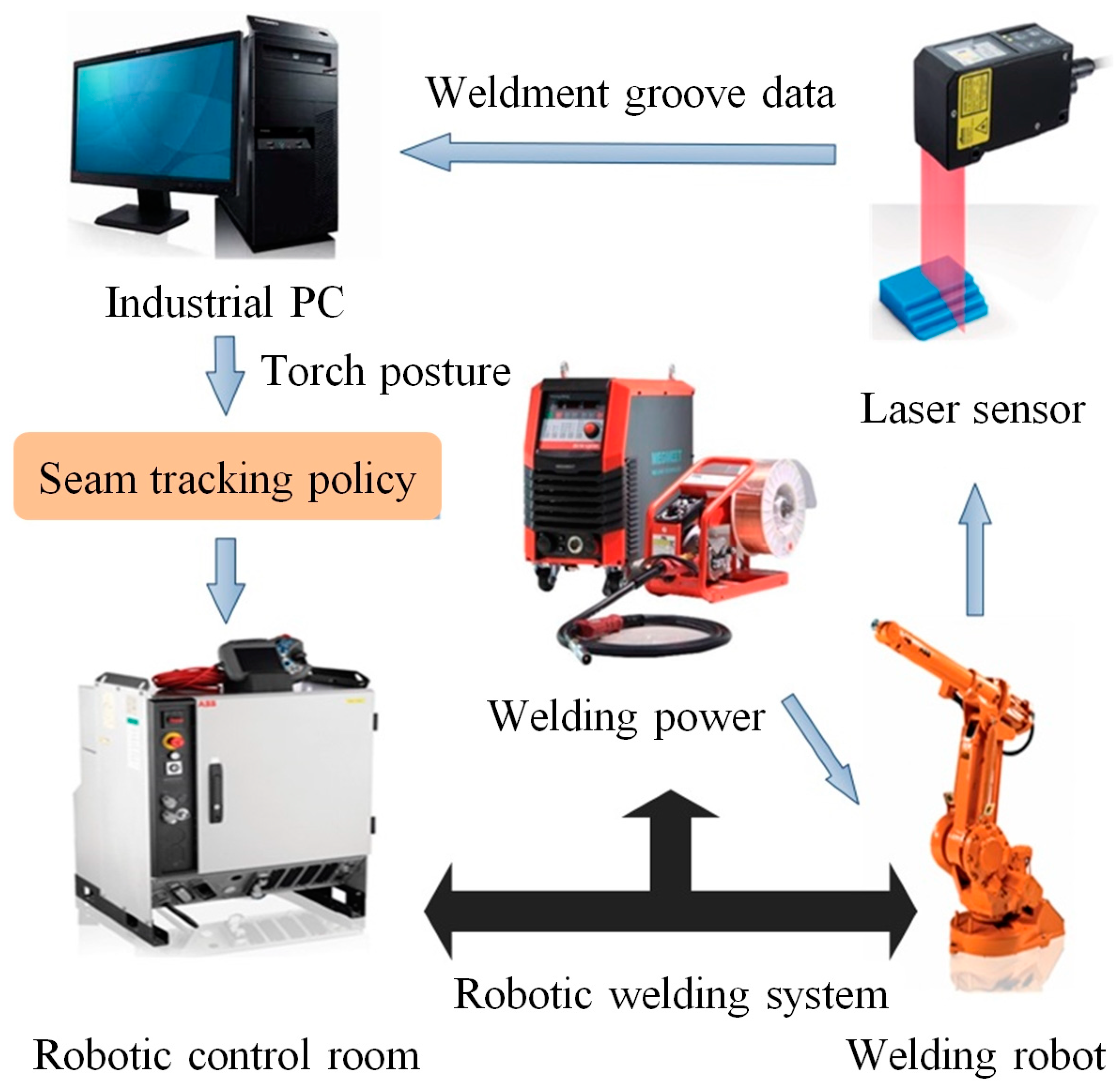
A welding seam tracking system consists of a welding robot, a sensor, an industrial personal computer (PC), a welding power supply, and a robotic control room. The scheme of the proposed system is shown in
Figure 1.
The sensors are set on the essential role in robotic seam tracking; many studies have been conducted on robotic seam tracking using sensors such as vision sensors, laser sensors, arc sensors, electromagnetic sensors, and ultrasonic sensors [
13]. In this paper, a laser displacement ranging sensor based on laser triangulation and projection conversion was used as a vision tool [
17]. By projecting and converting the captured image, and then calculating, and converting it into distance data, precise measurements of height and width can be achieved.
The proposed welding seam tracking system has been provided with laser measurement and computer vision technology. A basic laser sensor is mainly composed of a CCD camera, laser diode, and filter. The CCD camera is always assembled to the laser at an angle to capture the projection of laser on the weldment properly. The laser diode would generate a dot or stripe which would then be scanned by the camera. The offset of the welding robotic motion with respect to the robotic welding seam will be measured by the laser sensor.
As depicted in
Figure 1, the welding robot, robotic controller, and welding equipment make up the robotic welding system. A laser sensor is assembled at the bottom of the welding robot and driven by the welding robot to collect welding seam information, which is then transmitted through the connection between the laser sensor and the industrial PC. The welding path is generated by a novel seam tracking approach, which then will be transmitted to the robotic controller to instruct the robotic welding.
The main objectives of welding seam tracking are as follows: seam edge detection, starting and ending point detection, joint width measurement, and welding path positioning with regard to the co-ordinate frame of the robotic MAG welding.
3. Welding Seam Tracking Method
In this study, we proposed a novel welding seam tracking method oriented toward 3D complex weld seams through four steps: segment scanning, combined filtering processing, feature-point extraction, and welding path planning.
First, the original welding bevel data was collected by segmented scanning; the burr and distortion are removed by Lowess smoothing [
18] to restore the weld bevel contour shape. Subsequently, two successive derivatives, Gaussian [
19] filters and limiting [
20] filters were performed to obtain the bevel feature point coordinates in the laser sensor coordinate system {S}; through calibration, 2D coordinates of feature points located under laser sensor coordinate system {S} were transformed into 3D coordinates under the base coordinate system {B} [
21]; a series of welding points were then NURBS fitted [
22], and the welding path was finally be formed. A flow diagram of the proposed welding seam tracking method is presented in
Figure 2.
3.1. Segmented Scanning and Combined Filtering
The 3D spatial weldment has a large span in the vertical direction. When the distance to the laser sensor is relatively close during the scanning process, some welding seams may exceed the measurement range, and information cannot be collected, therefore resulting in the loss of information on some of the top weldment grooves. It is typically difficult to obtain the overall shape data of the spatial weldment grooves. Therefore, a segmented scanning method was proposed to obtain the 3D weldment groove shape data completely and accurately.
The welding robot drives the laser sensor to continuously scan the welding seam in a folded segmented approach to obtain the raw data, as shown in
Figure 3.
The experimental objects of this paper are the 2D symmetrical S-shaped and 3D spatial weldments. The 3D weldment was formed by a linear and a symmetrical S-shaped weldment. As the 3D weldment used in this paper was a two-segment overlapping type, intensive collection was conducted at the overlap, that is, at the junction of the Segment 3 and Segment 4 of the 3D weldment, the collection frequency was increased to prevent data distortion at the overlap of the weldment.
The principle and effect of segmented scanning for the 2D symmetrical S-shaped weldment are revealed in
Figure 4.
The data acquired by the laser sensor was affected by the natural light, reflections on the welding surface, and burr bumps. These effects resulted in the distortion of the acquired data. The combined filtering uses three methods: Lowess filtering, limiting filtering, and Gaussian filtering to smoothly correct the data graph.
Lowess filtering is a weighted linear least squares method combined with a first-order polynomial model, which can better smooth the volatile data and is used to deal with distortions such as welding surface burrs. The welding bevel data were averaged and regressed by Equation (1), and the process introduces the weighted smoothing of Equation (2) to derive the Lowess estimator Equation (3):
where
is the average value of the
y-axis coordinates of all points on the groove scanned by the laser sensor,
is the
y-axis coordinate of a point on the groove scanned by the laser sensor,
is the
x-axis coordinate of a point on the groove scanned by the laser sensor,
is the set of all points on a certain groove section,
is the horizontal coordinate of the initial scanning point, and
is the number of scanning points.
Additionally,
,
, where
is just a parameter, and
.
is the window width.
Here,
is the weight.
The limiting filtering principle is presented in Equation (4), which is used to deal with pulse disturbances caused by chance factors:
where
and
are the sampling values, and
is the threshold value.
Gaussian filtering can effectively suppress the interference signals of normal distribution and prevent local peaks in the detection results. The one-dimensional expression of the Gaussian function is written as:
where
is the mean value, which determines the position of the Gaussian function, and
is the standard deviation, which determines the amplitude of the distribution.
In the process of processing 3D spatial welding bevels, Lowess filtering is used to smooth the original shape of the welding bevel. Limiting filtering and Gaussian filtering are used to process the first-order and second-order derivatives to make the local great minima more significant. The different combined filtering effects are represented in
Figure 5, with
.
and
representing the values on the
x axis,
y axis, and
z axis, respectively.
3.2. Feature-Point Extraction
The final accuracy of welding seam tracking is influenced by the accuracy and speed of the feature-point extraction. A feature-point extraction algorithm consists of five steps for a 3D complex welding seam, as illustrated in
Figure 6.
As evident from the plot in
Figure 6, Lowess filtering smooths the seam welding bevel firstly; the first-order derivative of the welding bevel profile is then derived; the first-order derivative is smoothed using the limiting filtering and Gaussian filtering; the second-order derivative is then derived and smoothed; and finally, the global minimum and maximum values are calculated to find the required coordinates of the seam feature points.
3.3. Path Planning
As the seam data measured by the laser sensor is based on its own coordinate systems, converting the feature points into the base coordinate system {B} of the welding robot through pose calibration is necessary [
23]. A spatial conversion relationship between the coordinate systems in the seam tracking system is the basis to support subsequent research and calculations.
The coordinate conversion of experimental data could be used for path planning. That is, the experimental data of 2D coordinates under the sensor coordinate system {S} is converted into 3D coordinates under the base coordinate system {B}. This conversion process involves the end flange coordinate system {E}, and the robotic welding torch coordinate system {T}. Each coordinate system of the robotic welding system is compared in
Figure 7.
,
,
representing the coordinate axis of the sensor coordinate system {S}, respectively.
,
,
representing the coordinate axis of the base coordinate system {B}, respectively.
,
,
representing the coordinate axis of the end flange coordinate system {E}, respectively.
,
,
representing the coordinate axis of the robotic welding torch coordinate system {T}, respectively.
To perform the first step of the coordinate system conversion, the welding robot TCP (tool center point) calibration of welding torch was conducted [
24]. The compatibility conditions and the governing statics and dynamics equations have been combined to find the transformation matrix of the robot [
25]. The transformation matrix
of the welding torch coordinate system {T} to the end flange coordinate system {E} was found using the six-point method [
26]. By selecting a suitable fixed corner point on the calibration block as the calibration point, the welding robot’s motion was controlled to ensure that the welding torch posture changed significantly to the greatest extent, and conformed to a spherical uniform distribution, which can thereby effectively improve the accuracy and stability of the calibration.
Then, the laser sensor calibration was performed using the three-point method [
26] to find the transformation matrix
between the sensor coordinate system {S} and end flange coordinate system {E}. Three fixed points in space were selected as the calibration reference points; the laser sensor collects the coordinate data of the calibration point and records the pose data of the end flange coordinate system {E}, which can obtain the transformation matrix
of the base coordinate system {B} to the end flange coordinate system {E}.
To improve the reliability and accuracy of the calibration results, the welding torch calibration experiment was repeated three times to obtain three sets of welding robot pose data, and the results were then averaged. The computed results of the transformation matrix
and
are shown in Equation (6).
In addition, the coordinate transformation relationships of the calibration points between the base coordinate system {B} and the sensor coordinate system {S} are as follows:
where
,
.
The trivial NURBS fitting method is more convenient in fitting complex shapes, and the fitting and interpolation of NURBS curves are also the focus of research in this field. The NURBS curves fitting formula can be written as [
22]:
where
are the weight factors, and
, which is respectively associated with the control point
, and
is the number of control points. The first and last weight factors were
and
, with the other weight factors,
. All
weight factors arranged in order were not all arranged as zero at the same time to prevent the denominator from being zero.
is the
B spline basis function determined by the node vector
, as according to the de Boor-Cox evaluation scheme [
27].
4. Experimental Procedures
Experimental demonstrations were conducted using the proposed welding seam tracking algorithm to instruct the motion of the robotic welding torch. A prototype of whole welding experimental system in this paper is presented in
Figure 8, which includes a welding robot (ABB, IRB1410. Shanghai, China) with the position repeatability of 0.025 mm, a laser displacement ranging sensor (OPTEX, LS-100CN. Dongguan, China) with a linear accuracy of ±0.1%F.S and a sampling period of 0.5 ms, a robotic controller (ABB, IRC5, Shanghai, China), a welding power source (MEGMEET, Ehave CM350. Shenzhen, China), a welding torch, a communication module (TEXAS, RS-485. Chengdu, China), and a host computer (Lenovo, ThinkPad X1., Shanghai, China).
Through robotic MAG welding experiments under actual testing conditions, welding seam geometry and morphology images of seam molten pool under different welding characteristics were able to be produced.
As mentioned in
Section 3, we chose a 2D symmetrical S-shaped and a 3D spatial weldment as the two typical experimental weldments in this paper to verify the feasibility by measuring the tracking accuracy. Two typical welding grooves with a 2D symmetrical S-shape and a 3D curve are represented in
Figure 9.
In the experiment, the moving speed and acquisition frequency of the welding robot were set to be 20 mm/s and 12 Hz, respectively [
28]. The 2D information of the collected welding seam was retained and visualized with the time as the third dimension, as shown in
Figure 10.
It can be seen from the above figures that the overall characteristics of the welding seam without coordinate transformation are unapparent and does not display the overall shape of the symmetrical S-shaped welding seam. However, the bevel characteristics were not masked. Coordinate transformation was performed on the raw data to restore the spatial characteristics of the welding seam.
The welding seam information collected by the laser sensor was the 2D coordinate data, which was affected by the interference of the experimental environment and laser scattering, resulting in distortion and burrs of the data. The method described in
Section 3 was used to combine the raw data for filtering.
5. Results and Discussion
Using the methods mentioned in
Section 3, the welding seam feature points were extracted to obtain its coordinates under the laser sensor coordinate system {S}. Afterwards, the coordinates of the welding feature points under the base coordinate system {B} were calculated according to Equations (6) and (7). The welding points were obtained by taking the center points of each pair of feature points.
The weld points were then fitted using the NURBS function to produce a welding path. The end of the robotic welding torch was used to fall on the centerline of the welding seam, and the position data was recorded as a benchmark. The welding path obtained under the proposed tracking method was then compared with the benchmark to obtain the tracking error.
The fitted welding path of two typical welding seams together with the point clouds frame of the weldments were compared in
Figure 11. Comparing them with the characteristics shown in
Figure 10, the overall features of the welding seams were found to be restored, which therefore provides the basis for the implementation of welding seam tracking.
The experimental tracking results of the 3D complex welding seams are presented in
Figure 12. The red curve in the figure is the desired welding path, which was used as the welding path benchmark; the actual welding path is shown below the red curve.
The end of the welding torch was moved along the center line of the welding seam by the “teaching-playback” mode [
3], and the pose data of the welding robot during the movement was recorded to generate a reference path, which was then used as the basis for calculating the welding seam tracking error.
Two typical welding seam tracking errors for the 2D symmetrical S-shaped and 3D curved weldments in the paper are depicted in
Figure 13. As evident from the plot in
Figure 13, the average errors of the two typical weldments were 0.296 mm and 0.292 mm, respectively.
It is worth mentioning that the average deviations of the two typical welding seams of the 2D symmetrical S-shape and 3D curve are far less than 0.5 mm, which could therefore satisfy the needs of the minimum accuracy for the conventional welding robot as defined by Kovacevic et al. [
29].
In addition, the standard deviations of two typical welding seams were calculated as 0.0779 and 0.1129, respectively. It was noticeable that the smaller the standard deviation, the smaller the error fluctuation in the welding processes.
Comparison of the welding seam tracking errors under different methods conducted by five other scholastic studies (Shen et al. [
6]; Park et al. [
7]; Banafian et al. [
8]; Xue et al. [
9]; and Zhang et al. [
13]) is listed in
Table 1. Experimental investigations demonstrated the validity of our proposed welding seam tracking approach in this paper and can provide a reference for the research on high-precision seam tracking.
6. Conclusions
A novel welding seam tracking approach and experimental demonstrations oriented towards 2D symmetrical S-shaped and 3D curved welding seams in robotic MAG welding processes were introduced in this paper. Conclusions and perspectives are as follows:
This paper introduced the composition and structure of the welding seam tracking system, analyzed its working principle and process, and proposed a four-step seam tracking method with segmented scanning, combined filtering, feature-point extraction, and welding path planning for the 2D symmetrical S-shaped and 3D curved welding seams based on the laser sensor.
A set of seam four-step tracking systems was used to scan the welding seam in segments and obtain the original data; the data was smoothed using three combinations of filtering; the feature points of welding seam were extracted and then the coordinates of welding points were provided; and the welding path was obtained by interpolation of the welding points.
Welding seam tracking experimental investigation was conducted for two typical welding seams of a 2D symmetrical S-shape and a 3D curve. The tracking errors were 0.296 mm and 0.292 mm at a welding speed of 20 mm/s, respectively. Experiments showed that the proposed approach resulted in a far greater accuracy than those studies mentioned in
Section 1.
The possible directions of future work comprise the following ideas. In order to achieve better tracking performances for 3D complex welding seams, multi-sensor information fusion technology, reinforcement learning, and deep neural networks could be applied to the image processing flow of welding seams and the quality inspection of complex weldments. For instance, X-ray image and convolutional neural networks (CNNs) could be used for the detection and recognition of the weld seam defects; convolution filter and deep reinforcement learning (RL) could be combined to localize the weld feature point in each welding image; and visual tracking and object detection based on a deep learning (DL) framework could be proposed to address the problem of low welding precision caused by possible external environmental disturbances.
Author Contributions
Conceptualization, G.Z. and J.H.; methodology, G.Z. and Y.W.; software, Y.W. and G.Y.; validation, G.Z. and S.D.; formal analysis, G.Z. and J.H.; investigation, G.Z. and Y.W.; resources, G.Z. and X.C.; data curation, S.D. and Y.W.; writing—original draft, G.Z.; writing—review and editing, G.Z. and K.S.; visualization, X.C.; supervision, G.Z. and H.Y.; project administration, G.Z. and H.Y.; funding acquisition, G.Z. All authors have read and agreed to the published version of the manuscript.
Funding
This research was funded in part by the National Natural Science Foundation of China, grant number 62073092, the National Key Research and Development Project of China, grant number 2018YFA0902900, the Guangdong Provincial Natural Science Foundation, grant number 2021A1515012638, the Open Fund of Fujian Key Laboratory of Intelligent Machining Technology and Equipment (Fujian University of Technology), grant number KF-01-22005, the Guangzhou Municipal Basic Research Program, grant number 202002030320.
Institutional Review Board Statement
Not applicable.
Informed Consent Statement
Not applicable.
Data Availability Statement
The data presented in this study are openly available in [A Novel 3D Complex Welding Seam Tracking Method in Symmetrical Robotic MAG Welding Process Using a Laser Vision Sensing—research data] at [
https://cloud.huawei.com/home#/collection/v2/all] (accessed on 12 April 2023.).
Acknowledgments
The authors would like to express their thanks to the Guangzhou Institute of Advanced Technology for helping them with the experimental characterization.
Conflicts of Interest
The authors declare no conflict of interest.
References
- Kim, I.S.; Son, J.S.; Lee, S.H.; Yarlagadda, P.K.D.V. Optimal design of neural networks for control in robotic arc welding. Robot. Comput. Integr. Manuf. 2004, 20, 57–63. [Google Scholar] [CrossRef]
- Cao, Y.; Zhu, S.; Liang, X.B.; Wang, W.L. Overlapping model of beads and curve fitting of bead section for rapid manufacturing by robotic MAG welding process. Robot. Comput. Integr. Manuf. 2011, 27, 641–645. [Google Scholar] [CrossRef]
- Huang, Y.J.; Yong, Y.S.; Chiba, R.; Arai, T.; Ueyama, T.; Ota, I. Kinematic control with singularity avoidance for teaching-playback robot manipulator system. IEEE Trans. Autom. Sci. Eng. 2016, 13, 729–742. [Google Scholar] [CrossRef]
- Ogbemhe, J.; Mpofu, K. Towards achieving a fully intelligent robotic arc welding: A review. Ind. Robot. 2015, 42, 475–484. [Google Scholar] [CrossRef]
- Zhou, P.; Peng, R.; Xu, M.; Wu, V.; David, N.A. Path planning with automatic seam extraction over point cloud models for robotic arc welding. IEEE Robot. Autom. Lett. 2021, 6, 5002–5009. [Google Scholar] [CrossRef]
- Shen, H.Y.; Lin, T.; Chen, S.B.; Li, L.P. Real-time seam tracking technology of welding robot with visual sensing. J. Intell. Robot Syst. 2010, 59, 283–298. [Google Scholar] [CrossRef]
- Park, J.H.; Moon, H.S. Advanced automatic welding system for offshore pipeline system with seam tracking function. Appl. Sci. 2020, 10, 324. [Google Scholar] [CrossRef]
- Banafian, N.; Fesharakifard, R.; Menhaj, B. Precise seam tracking in robotic welding by an improved image processing approach. Int. J. Adv. Manuf. Tech. 2021, 114, 251–270. [Google Scholar] [CrossRef]
- Xue, K.X.; Wang, Z.J.; Shen, J.Q.; Hu, S.S.; Zhen, Y.H.; Liu, J.; Wu, D.Y.; Yang, H. Robotic seam tracking system based on vision sensing and human-machine interaction for multi-pass MAG welding. J. Manuf. Process. 2021, 63, 48–59. [Google Scholar] [CrossRef]
- Fang, Z.J.; Weng, W.W.; Wang, W.J.; Zhang, C.; Yang, G.L. A vision-based robotic laser welding system for insulated mugs with fuzzy seam tracking control. Symmetry 2019, 11, 1385. [Google Scholar] [CrossRef]
- Parameshwaran, R.; Maheswari, C.; Nithyavathy, N.; Govind, R.R.; Selvakumar, N.; Dharshan, V.R.D.; Vasanth, M. LABVIEW based simulation on weld seam tracking using edge detection technique. IOP Conf. Ser. Mater. Sci. Eng. 2021, 1055, 012026. [Google Scholar] [CrossRef]
- Lei, T.; Huang, Y.; Wang, H.; Rong, Y.M. Automatic weld seam tracking of tube-to-tube sheet TIG welding robot with multiple sensors. J. Manuf. Process. 2021, 63, 60–69. [Google Scholar] [CrossRef]
- Zhang, G.; Zhang, Y.H.; Tuo, S.H.; Hou, Z.C.; Yang, W.L.; Xu, Z.; Wu, Y.Y.; Yuan, H.; Shin, K.S. A novel seam tracking technique with a four-step method and experimental investigation of robotic welding oriented to complex welding seam. Sensors 2021, 21, 3067. [Google Scholar] [CrossRef] [PubMed]
- Hong, B.; Jia, A.T.; Hong, Y.X.; Li, X.W.; Gao, J.P.; Qu, Y.Y. Online extraction of pose information of 3D zigzag-line welding seams for welding seam tracking. Sensors 2021, 21, 375. [Google Scholar] [CrossRef] [PubMed]
- Inoue, F.; Derakhshandeh, J.; Lofrano, M.; Beyne, E. Fine-pitch bonding technology with surface-planarized solder micro-bump/hybrid for 3D integration. Jpn. J. Appl. Phys. 2021, 60, 026502. [Google Scholar] [CrossRef]
- Kou, R.K.; Sun, H.W.; Zhao, X.X.; Zhu, J.L. Domestic Research Progress of Ship Curved Seam Tracking Technology. Hot Work. Technol. 2022, 51, 7–12. [Google Scholar] [CrossRef]
- Xiao, R.Q.; Xu, Y.L.; Hou, Z.; Chen, C.; Chen, S.B. An automatic calibration algorithm for laser vision sensor in robotic autonomous welding system. J. Intell. Manuf. 2022, 33, 1419–1432. [Google Scholar] [CrossRef]
- Yi, Z.G.; Pan, N.; Liu, Y.; Guo, Y. Study of laser displacement measurement data abnormal correction algorithm. Eng. Comput. 2017, 34, 123–133. [Google Scholar] [CrossRef]
- Zheng, X.G. GPNRBNN: A robot image edge detection method based on Gaussian positive-negative radial basis neural network. Sens. Imaging 2021, 22, 33. [Google Scholar] [CrossRef]
- Aadhi, A.; Kovalev, A.V.; Kues, M.; Roztocki, P.; Reimer, C.; Zhang, Y.B.; Wang, T.; Little, B.E.; Chu, S.T.; Wang, Z.M.; et al. Highly reconfigurable hybrid laser based on an integrated nonlinear waveguide. Opt. Express 2019, 27, 25251–25264. [Google Scholar] [CrossRef]
- Xu, J.; Hoo, J.L.; Dritsas, S.; Fernandez, J.G. Hand-eye calibration for 2D laser profile scanners using straight edges of common objects. Robot. Comput. Integr. Manuf. 2022, 73, 102221. [Google Scholar] [CrossRef]
- Liu, Y.; Shi, L.; Tian, X.C. Weld seam fitting and welding torch trajectory planning based on NURBS in intersecting curve welding. Int. J. Adv. Manuf. Tech. 2018, 95, 2457–2471. [Google Scholar] [CrossRef]
- Muhammad, J.; Altun, H.; Abo-Serie, E. Welding seam profiling techniques based on active vision sensing for intelligent robotic welding. Int. J. Adv. Manuf. Tech. 2017, 88, 127–145. [Google Scholar] [CrossRef]
- Cakir, M.; Deniz, C. High precise and zero-cost solution for fully automatic industrial robot TCP calibration. Ind. Robot 2019, 46, 650–659. [Google Scholar] [CrossRef]
- Cammarata, A.; Sinatra, R.; Maddio, P.D. Static condensation method for the reduced dynamic modeling of mechanisms and structures. Arch. Appl. Mech. 2019, 89, 2033–2051. [Google Scholar] [CrossRef]
- Qiao, G.F.; Sun, D.L.; Song, G.G.; Wen, X.L.; Wei, Z.; Song, A.G. A rapid coordinate transformation method for serial robot calibration system. J. Mech. Eng. 2020, 56, 1–8. [Google Scholar] [CrossRef]
- Tsao, N.K.; Sun, T.C. On the numerical computation of the derivatives of a B-spline series. IMA J. Numer. Anal. 1993, 13, 343–364. [Google Scholar] [CrossRef]
- Zhang, K.; Jiang, H.T.; Meng, Q.; Tang, D.; Lin, H.T. Effect of the welding speed on the microstructure and the mechanical properties of robotic friction stir welded AA7B04 aluminum alloy. Chin. J. Eng. 2018, 40, 1525–1532. [Google Scholar] [CrossRef]
- Zhang, S.B.; Zhang, Y.M.; Kovacevic, R. Noncontact ultrasonic sensing for seam tracking in arc welding processes. J. Manuf. Sci. Eng. 1998, 120, 600–608. [Google Scholar] [CrossRef]
| Disclaimer/Publisher’s Note: The statements, opinions and data contained in all publications are solely those of the individual author(s) and contributor(s) and not of MDPI and/or the editor(s). MDPI and/or the editor(s) disclaim responsibility for any injury to people or property resulting from any ideas, methods, instructions or products referred to in the content. |
© 2023 by the authors. Licensee MDPI, Basel, Switzerland. This article is an open access article distributed under the terms and conditions of the Creative Commons Attribution (CC BY) license (https://creativecommons.org/licenses/by/4.0/).

 ,
, 


