Abstract
The rapid growth of energy demand requires progressive energy generation. This, together with the demand for higher efficiency and flexibility, has promoted the application of power electronics in energy systems. During the past decade, model predictive control (MPC) of power electronics has witnessed significant advancements in both dynamic performance and optimal control of the multi-objective terms. Several of these terms can have equal control priorities, resulting in a symmetrical cost function; however, most objectives have different priorities and require weighting factors to resolve the asymmetry in the cost function. Currently, researchers continue to encounter challenges in the optimal design of weighting factors. Moreover, the relative performance of different techniques that either utilize or avoid the weighting factor are uncertain. Therefore, this study focuses on weighting factor design techniques in the literature as applied to wind/solar energy conversion, microgrids, grid-connected converters, and other high-performance converter-based systems. These are grouped under the heuristic, offline tuning, sequential, and online optimization methods. This study demonstrates that optimal online tuning of weighting factors and sequential MPC methods can both offer improved robustness against parameter uncertainties. In addition, the advantages and limitations of different techniques are highlighted.
1. Introduction
Model predictive control is emerging as a popular control technique with applications in cross-disciplinary domains. Over the past half-century, it has found industrial relevance in petrochemical, aerospace, and automotive processing and manufacturing. Despite the initial introduction of MPC to power electronics control in the 1980s, its ascendancy has occurred over roughly the past two decades [1]. This resurgence has been attributed to the emergence of fast microprocessors with the capability to meet the high computational needs of MPC. MPC can be grouped into finite control set MPC (FCS-MPC) and generalized predictive control [2]. However, FCS-MPC (sometimes called direct MPC with reference tracking [1,3]) has been studied more extensively because of its intuitive features and ease of application. Despite its advantages, including high performance multi-objective control with constraints, FCS-MPC (henceforth simply called MPC) is limited by several challenges, among which is the optimal weighting factor design in the asymmetric cost function.
Three generic scenarios are typical in the design of weighting factors. First, certain multi-objective cost functions do not require weighting factors; they comprise sub-objectives with identical units or order of magnitudes. In cases such as this, there is usually a single variable being controlled which is split into different components in the cost function, for example, the voltage or current control of a voltage source converter or the control of complex power in a grid-connected converter. In the first case, where there is a three-phase or multi-phase system, the cost function has components for each coordinate axis (or phase) [4], e.g., . Similarly, complex power comprises active and reactive power, resulting in the weighting factor-free cost function [5,6].
Second, while the multi-objective terms are of equal priority, they have different units or magnitudes, making weighting factors necessary. In this case, the weighting factors must be set to 1 after ensuring that all magnitudes are made equal (usually by normalization) [7]. A common examble of this occurs in the torque and flux control of an induction machine drive [8]. Third, the multi-objective terms are of unequal priority, with certain terms having higher control priority than others. Examples of this case include predictive current control of a grid-connected rectifier with control input (switching frequency) regulation [9] and predictive current control with reactive power regulation [7].
The weighting factor is used to prioritize control objectives in the single asymmetric cost function to be optimized in MPC-based multi-objective control [10]. Thus, objectives with higher priority receive higher weight assignments. Based on this principle, researchers usually adjust values assigned to weight factors heuristically until performance indices are attained, including total harmonic distortion (THD), tracking error, average switching frequency, and steady-state stability. Nonetheless, this procedure hinders optimal MPC performance. Therefore, researchers in this field have devised several alternative approaches to overcome this challenge. These can be categorized as offline heuristic weighting factor tuning, sequential MPC, simplified model-based MPC, and online optimization tuning approaches comprising both artificial intelligence (AI)-based and non-AI-based methods.
Sequential MPC methods, called cascaded schemes in the literature, attempt to simplify the design process by indirectly achieving the purpose of the weighting factor, rendering it unnecessary [8]. Another method that avoids the weight factor is the simplified-model MPC. This can be applied where the competing control objectives can be analytically transformed into one parameter such that all objectives have the same unit [11,12,13]. Online optimization tuning utilizes an optimization algorithm to select the optimal weighting factor with respect to real-time plant and operational conditions [14,15], and can increase the computational burden of the controller. It comprises both non-AI-based and AI-based methods. AI-based online tuning schemes optimize the tuning process using genetic algorithms, fuzzy logic, and other AI schemes [16]. AI methods have been shown to have relatively low computational requirements in control applications [17].
These techniques have been validated in various applications. Sequential MPC has been applied to cascaded flying capacitor bridge (CFCB) multilevel converters [18], three-phase/two-leg/seven-level T-type nested NPC converters [19], and three-level neutral-point-clamped (NPC) back-to-back converter permanent magnet synchronous machine (PMSM) wind turbines [20]. The simplified model method has been applied to the induction motor and PMSM [11,12,21,22,23,24]. Online optimization of the weighting factor has been applied to quasi-Z-source PV inverters [25] and DC–DC single-ended primary-inductor converters (SEPIC) [26]. A more comprehensive classification and listing of applications is provided in Table 1.

Table 1.
Classification of weighting factor design techniques.
Review studies on MPC for power electronics and drives have been reported in past publications, revealing the basic concepts, strategies, applications, and benchmarking with classical control methods. In [2,58], the authors surveyed MPC of power converters with a focus on both academic and industrial aspects of the prediction model, the cost function, and the optimization algorithm. The predictive torque control of switched reluctance machine drives was covered in [59,60]. In [61], the authors surveyed the application of predictive control in battery and supercapacitor energy storage systems. In the field of electrical drives, [62] presented weighting factor calculation in the most relevant contributions published in the last few years, while [63] presented a performance comparison. The authors of [64,65] reviewed MPC applications for microgrid converters. In [66], the authors discussed the future trends and challenges of digital twins in the field of MPC for power electronics. However, none of these publications carried out a detailed study on the design of the weighting factor in the asymmetric cost function of MPC for converters and drives. In addition, there is as yet no study that provides a detailed quantitative comparison of the performance of different weighting factor design methods. To close this research gap, the present study focuses specifically on the methods for designing weighting factors (or indirectly achieving their purpose while avoiding their explicit use), which is a significant challenge that has been highlighted in several studies. Here, we provide a detailed comparison of design methods using their underlying mathematical principles, control schemes, and numerical results of dynamic performances. The contributions of this paper include:
- A detailed review of the design of weighting factors for the predictive control of power electronic converters;
- A detailed comparison of the design methods based on their underlying mathematical principles, control schemes, and numerical results of dynamic performances;
- Guidelines for the choice of weighting factor design method in power electronic applications.
The paper introduces the fundamentals of MPC and heuristic weighting factor tuning in Section 2. Three weighting factor design methods are presented as follows: sequential MPC in Section 3, simplified model MPC in Section 4, and online optimization-based tuning in Section 5. The relative performance of the different methods are compared in Section 6 on a symmetrical two-level back-to-back topology, and the final conclusions are drawn in Section 7.
2. Fundamentals of MPC for Power Converters
In this section, the underlying principles of MPC are discussed, including the system model and weighting factor.
2.1. System Model
The generic discrete model of a power converter is provided by (1), where is the discrete time step, is the state vector (with state variables that include the filter current/voltage and machine fluxes [58]), and is the output vector (with output variables including output current, voltage, active/reactive power, speed, and torque):
Considering a sequence of input variables over a prediction horizon time steps, a sequence of possible power converter switching states that the controller can implement can be defined as follows [58,67]:
The predictive controller seeks an optimal switching sequence
where J is the cost function that captures the control objectives for the optimization problem. In power converter systems, the control objective can track a reference by minimizing a tracking error magnitude as follows:
where is the penalty matrix on the tracking error, is the predicted output, is the reference, penalizes the control effort , and . MPC is a receding horizon scheme; therefore, only the first term of the sequence is applied to the plant. Recalculation of the next sampling instant’s predictions and optimal sequence is performed after the measurements/estimates of the states have been updated.
Detailed discussions on holistic design considerations for MPC, including the prediction horizon, control effort, weighting factor, and performance assessment, are outside the scope of this article, but can be found in [1]. In this work, the focus is on the design methods for optimal weighting factor tuning.
2.2. Heuristic Weighting Factor Tuning
As mentioned earlier, MPC can facilitate the optimal control of the multi-objective terms/parameters in a predictive cost function. Several of these parameters might have equal control priorities [68,69,70,71], which is ideal for symmetrical cost function designs. However, other control objectives may have differing priorities, e.g., torque and flux control in electrical machine drives. The latter case requires weighting factors in order to set the relative importance between the control objectives for optimal system performance (e.g., low current THD) in an asymmetric cost function. The conventional means of determining the value of the weighting factors rely on offline heuristic tuning, leading to sub-optimal control results [1]. In the following discourse, proposed solutions from the literature are subjected to objective analyses while highlighting the advantages and disadvantages associated with each method.
3. Sequential Model Predictive Control
Sequential MPC is a relatively new method that offers a solution to the challenges associated with tuning the weighting factors for MPC of power electronic converters. This method was introduced by [8], and operates on the concept of using multiple cost functions arranged in a cascaded/sequential order of computational execution, as shown in Figure 1. In the figure, n cost functions are arranged sequentially in decreasing order of priority, representing the cost function J (5a) broken into cascaded cost functions to (5b):
Note that here is the predicted term and is the reference . After the model prediction stage, the first cost function (representing the criterion of highest priority) is executed. The output of block comprises a sorted list of selected optimal voltage vectors that is made available to all subsequent cost function stages to . Stages to each optimize their respective individual cost functions using information about the prediction model and references. The final stage provides the switching signals of the overall optimal voltage vector for each sampling time.
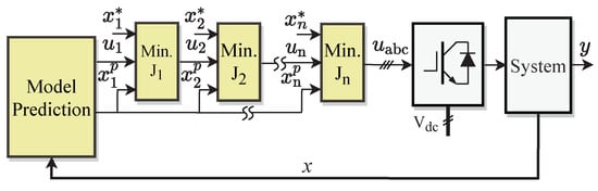
Figure 1.
Generic sequential MPC [8].
Two challenges arise with basic sequential MPC: first, the number of selected switching vectors from each stage could be too limited for optimal control of subsequent stages, and second, because the first stage is implicitly afforded the highest priority, there is a problem with applications in which all criteria/cost functions have equal priorities in a symmetrical structure. The first challenge is addressed to an extent by dynamic sequential MPC [20], while the second challenge can be solved using generalized sequential MPC [32] or even-handed MPC [29]. The dynamic sequential MPC approach shown in Figure 2 adaptively modifies the sorted list of selected optimal voltage vectors from each stage to include all vectors that satisfy a minimum error criterion [20], thereby providing better dynamic performance than when a static number of switching vectors is selected. Furthermore, both generalized sequential MPC [32] and even-handed MPC [29] overcome the inherent challenges of using a fixed sequence of execution for the cost functions. The even-handed method shown in Figure 3, for instance, adaptively selects the order of execution based on the simultaneous optimality of all criteria using a cross-error minimization process.
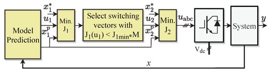
Figure 2.
Dynamic sequential MPC [20].
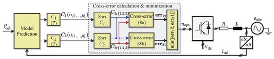
Figure 3.
Even-handed sequential MPC [29].
For instance, in a two-level inverter with eight voltage vectors , the control objectives can be for states and to track their references and , respectively. The criteria can be computed by normalization of the predicted errors for predicted terms and (where and are the rated values of and ):
Applying conventional sequential MPC sets as the priority criterion. However, this results in suboptimal results for , as illustrated in Figure 4. In this case, the three most optimal vectors relative to are , while is selected as the applied voltage vector; however, is not as optimal for as . Nonetheless, is excluded from the selection. Even-handed sequential MPC (EH-SMPC) provides a solution to this limitation.
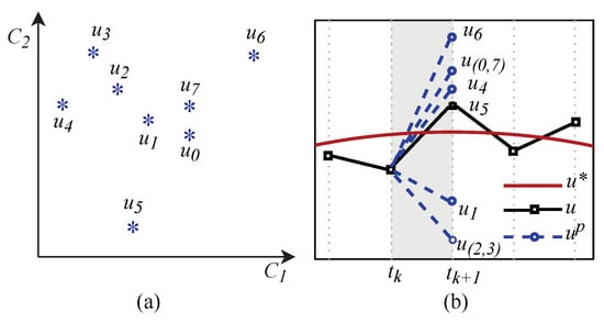
Figure 4.
Optimization limitations of conventional sequential MPC: (a) the plot of optimal voltage vectors and (b) the predicted and reference voltage vectors.
EH-SMPC improves optimization performance by introducing the concept of cross-errors. At each sampling instant, the following steps are executed:
Step 1: The voltage vectors are ranked for as follows: = , with rank being the most optimal and the least optimal.
Step 2: The three highest ranking voltage vectors for each of are selected for the cross-error stage, i.e., and .
Step 3: The cross-errors are computed as follows:
where , .
Step 4: The vectors of all cross-errors are minimized and mapped to the corresponding voltage vector for application to the plant.
Despite their relative ease of implementation, sequential MPC techniques have been shown to result in sub-optimal performance [1] to optimally-tuned weighting factors.
4. Simplified Model-Based MPC
Simplified model-based MPC methods aim to avoid the use of weighting factors by unifying the control objectives. This is possible where these control objectives are (in)directly interrelated. For instance, flux and torque can be unified in drive applications [11,12,13,21,22,23,24,35]. In addition, the model of multilevel converters can be simplified by reducing the number of switching states or introducing redundant voltage vectors without sacrificing good control performance [36,37]. The two cases of this method, i.e., unified control objectives and reduced switching states, are discussed in detail in this section.
The overall control scheme of a simplified MPC model with unified control objectives is shown in Figure 5 for a generic power converter system. It involves three basic control stages: state prediction, reference conversion, and cost function minimization. Without loss of generality, the figure applies to the case in which two states ( and ) need to be controlled via a single predictive cost function without the use of a weighting factor. Because these states are usually defined in different units, e.g., flux and torque, the crucial step in this method is the reference conversion of both states to the same unit. This can be accomplished by converting one state’s reference to the other (e.g., to , or vice-versa), as was the case in [11,12,13,21,23,24,35] for torque to flux reference conversion and [72,73] for flux to torque reference conversion. Alternatively, a third variable can be introduced, and references and can both be converted to , as was the case in [11] for flux and torque to voltage reference conversions. For improved steady-state performance, modifications to Figure 5 can include two optimal switching vectors per cycle instead of one. To achieve this, two stages can be added for second vector selection, duty ratio optimization, and pulse generation control (Figure 6) [11].
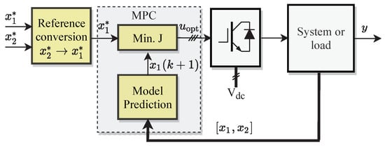
Figure 5.
Generic simplified FCS-MPC of power converter systems.
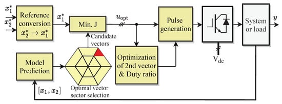
Figure 6.
Simplified FCS-MPC with two-vector control for electrical drive [11].
The use of reduced switching states/redundant voltage vectors is a means of simplifying the MPC of multilevel converters such as neutral-point clamped converters [43], nested neutral-point clamped converters [44], matrix converters [39], rectifiers [43], and quasi-Z-source converters [42]. These converters are modeled with per-phase (e.g., MMC for HVDC [36,37,38,45,46]), and the three-phase concepts (e.g., motor drives [39]). The control objectives include the DC-link current ripple, sub-module voltage ripple, circulating current, output current, and sub-module capacitor voltage. Furthermore, while most studies were on FCS-MPC, few reported modulated MPC with constant switching frequency [45,46].
Due to the modular design of multilevel converters, the calculation burden of the control scheme increases with the number of sub-modules or cells. Therefore, in order to decrease the computational burden, methods of reducing the number of applied switching states have been investigated in the literature. Figure 7 shows a simplified MPC scheme for application in multilevel converters. It requires a current reference generation stage to optimize the cost function J. This is not done for all the available switching states, which could be as large as (where N is the number of sub-modules per arm); instead, an optimized set of redundant voltage vectors is generated for the cost function optimization process, reducing the computational burden to [38]. The literature has focused significantly on applying variants of this scheme to modular multilevel converters for HVDC [36,37,38,43,45,46]. Among these, only [45,46] have presented designs for modulated MPC with fixed switching frequencies, with all others using variable switching frequencies.
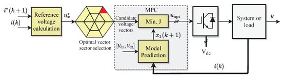
Figure 7.
Generic simplified FCS-MPC for multilevel converters [38].
5. Online Optimization Methods
In this section, the online calculation of the optimal weight factor is discussed under the headings of AI-based tuning and non-AI-based optimization.
5.1. Artificial Intelligence-Based Tuning Methods
Artificial intelligence (AI) is associated with enabling machines to use intelligence in ways that mimic human learning and reasoning [74]. In the broad field of power electronics, four groups of AI techniques have been applied: expert systems, fuzzy logic, metaheuristic techniques, and machine learning [74]. Among these, the latter three have been applied to MPC weighting factor design in the literature.
Fuzzy logic, the most popular among AI methods in weighting factor design, forms rules using Boolean logic while taking uncertainties into consideration. It has been applied to electrical machine drives [56,57].
Metaheuristic techniques (e.g., genetic algorithms, particle swarm optimization) utilize biological processes for mathematical optimization [74]. A multi-objective genetic algorithm was employed in [16] to tune weighting factors for torque, flux, and switching frequency for model predictive torque control of an induction motor drive. The dynamic performance was reported to be better than when using a heuristic tuning process. Machine learning can be categorized into supervised learning (using labeled training datasets), unsupervised learning (using unlabeled datasets), and reinforcement learning (which does not require training datasets) [74]. Among several existing machine learning methods, only neural networks (a form of supervised learning) have been applied to online weighting factor optimization. The neural network approach has been used for a three-level neutral-point clamped converter [54], a two-level voltage source converter [55], and predictive torque control of an induction machine [17]. In contrast to previous methods that are trained offline, an online self-training neural network method was proposed in [53] for a seven-level modified packed U-cell (MPUC7) active rectifier, combining particle swarm algorithm optimization for multi-weight factor tuning and a decoupled Lyapunov stability objective to guarantee control stability. In summary, machine learning methods are notable and have promising potential because they do not add significantly to the computational burden and can provide high accuracy.
5.2. Non-AI-Based Online Optimization
Online optimization techniques carry out real-time optimization of the weighting factors in multi-objective predictive control of power converters. Because all calculations required to accurately determine the optimal weighting factor are performed online, these techniques generally increase the computational burden of the predictive control process. Methods employed in the literature include tracking error optimization [14,25,26,47,48], coefficient of variation [50], state normalization/variable sensitivity balance [51], and continuous function of pre-existing error [52]. To facilitate the optimal weight factor calculation for predictive torque and flux control in particular, algebraic methods are presented in [75], and these are not computationally-intensive. Figure 8 depicted an example for online autotuning of weighting factors [14,47], described in Algorithm 1.
| Algorithm 1 Autotune Weight Factor [14,47] |
|
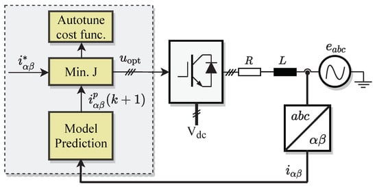
Figure 8.
Online optimization of weighting factors [14,47].
6. Case Studies
In this section, the relative dynamic and steady-state performances of the different methods reviewed above are compared.
6.1. System Description and Modeling
Figure 9 illustrates the system to be controlled. It comprises a machine-side converter (MSC) that functions as an active front-end rectifier connected to a DC-link capacitor, which supplies a grid-side converter (GSC). For greater modeling simplicity, the wind turbine is directly mounted on the PMSG shaft without any interfacing gearbox. The system parameters are provided in Table 2. In order to remain within the scope of this paper, the details of the mathematical models and state predictions for the MSC and GSC can be found in [76,77] and are not repeated here.
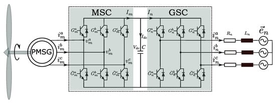
Figure 9.
Simplified power circuit of a grid-connected voltage source back-to-back power converter PMSG wind turbine system with RL filter, where and are the generator and grid-side current vectors, respectively, is the output voltage vector of the generator, is the grid voltage vector, and and are the filter stator resistance and inductance, respectively.
Table 2.
Parameters in the hardware-in-the-loop test.
Four control schemes in the references were implemented on real-time hardware-in-the-loop (HiL) PLECS RT-Box devices (Figure 10) and compared: classical MPC [76], sequential MPC [77,78], even-handed sequential MPC [29], and online-tuned weighting factor-based MPC [14]. The HiL approach executes the actually compiled codes on a real microprocessor. Hence, its verification is more convincing than simulations. In addition, the HiL test provides controller validation at a low cost and with great flexibility. The test bench, shown in Figure 10, is composed of two PLECS RT Boxes. One of the RT boxes emulates the PMSG wind turbine system. To obtain accurate results, the switching behavior of the power converter has been modeled here. The other is used as a real-time controller to run the mentioned control algorithm. The plant emulator captures the switching signals generated by the controller, and the controller then uses analog-to-digital (AD) input channels to receive the feedback signals from the plant. Therefore, the test bench is close to the real system, taking into account the time delays in sampling, transmission, and calculation.
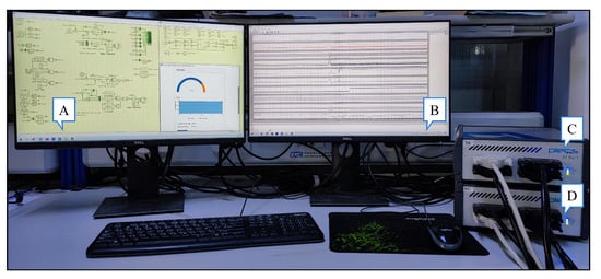
Figure 10.
Real-time hardware-in-the-loop test-bench. A: PLECS user interface; B: signal monitor; C: real-time controller; D: plant emulator.
Three key performance indices were used to compare the studied control methods, namely, power/voltage ripples, current THDs, and average switching frequency. These are defined as follows:
- Ripples (%): The total ripples of a state variable x, computed as follows:where x represents power or voltage, is the maximum value of x, is the average value of x, and is the rated value of x.
- Total harmonic distortion (THD): THD is a measure of the distortion of the signal that arises from harmonics. Current THD is calculated as follows:
- Average switching frequency (): This is computed as the average number of switch changes per sampling period:where N is the number of samples per second, is the sampling period, and represents the switch change at a given sampling instant.
6.2. Overall Performance
Figure 11 shows the overall control performance without any mismatch in the model parameters (Case A), while the ripple and THD data are collected in Table 3. For all four control methods, three step parameter changes were effected to test the transient performance of the control schemes. The speed reference was changed from 0.85 p.u. to 1.15 p.u. at 0.06 s. The DC-link voltage was changed by p.u. at 0.12 s. Finally, a pulse reactive power reference change of 1 p.u. was initiated at 0.18 s.
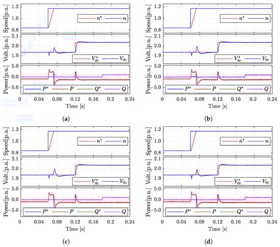
Figure 11.
Dynamic performance for Case A (without parameter mismatch): (a) classical model predictive control; (b) sequential model predictive control; (c) even-handed sequential model predictive control; (d) model predictive control with online-tuned weighting factor. Top to bottom: machine speed, DC-link voltage, and grid-side power, respectively.
Table 3.
Performance without parameter mismatch.
Under nominal parameter conditions, the performance of the DC-link voltage and power tracking for the four schemes were identical in their rapid response and low level of ripples. As presented in Table 3, there is little difference in the current THD and average switching frequency resulting from the four methods. On the other hand, the even-handed MPC scheme has the best tracking performance, with no spikes during any the transients described earlier. The online-optimized method has good tracking as well, with second-lowest reactive power spikes during transients. Sequential MPC has low ripples, but has the highest reactive power tracking error.
6.3. Performance under Parameter Uncertainties
Figure 12 shows the overall control performance with the actual inductance set to 1.5 versus in the controller. The same transients described earlier for the case without parameter mismatch were applied. Figure 13 and Figure 14 show the machine-side and grid-side current THD in steady-state. All data are summarised in Table 4. As in the previous case, the performance of the DC-link voltage and active power tracking for the four schemes is identical in terms of the rapid response and low levels of ripples. Although even-handed sequential MPC has the highest voltage overshoot after the reference voltage step change, it produces the best overall performance for reactive power tracking. Meanwhile, the tracking accuracy of classical MPC is the worst in the case of parametric mismatch.
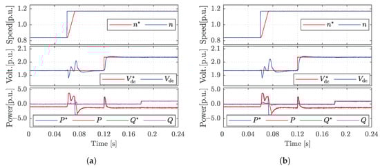
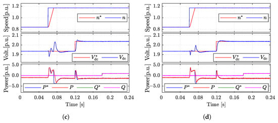
Figure 12.
Dynamic performance for Case B (with parameter mismatch): (a) classical model predictive control; (b) sequential model predictive control; (c) even-handed sequential model predictive control; (d) model predictive control with online-tuned weighting factor. From top to bottom: machine speed, DC-link voltage, and grid-side power, respectively.
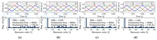
Figure 13.
Machine-side steady-state performance for Case B (with parameter mismatch): (a) classical model predictive control; (b) sequential model predictive control; (c) even-handed sequential model predictive control; (d) model predictive control with online-tuned weighting factor. From top to bottom: the machine-side current and its total harmonic distortion (THD).
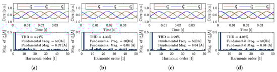
Figure 14.
Grid-side steady-state performance for Case B (with parameter mismatch): (a) classical model predictive control; (b) sequential model predictive control; (c) even-handed sequential model predictive control; (d) model predictive control with online-tuned weighting factor. From top to bottom: the grid-side current and its total harmonic distortion (THD).
Table 4.
Performance with parameter mismatch.
Consistent with these results, a number of the aforementioned methods have been reported to provide enhanced robustness against parameter uncertainties. In particular, online optimization [14] and EH-SMPC [29]. When a system operates optimally at nominal parameter values, it has nominal operating-point weighting factors for all the weighted cost function elements. However, when there are model parameter mismatches this corresponds to a change in the operating point, and new weighting factors need to be computed. This is demonstrated by the predictive current control of a motor load (modeled as a back-electromotive force (EMF) in series with load) in Figure 3 (EH-SMPC) and Figure 8 (online optimization of weighting factor). In Figure 3, two cost functions (11) are optimized in an even-handed manner:
In Figure 8, a single cost function (12) with a weighting factor is used:
The zoomed plots in Figure 15 illustrate the current responses under two conditions: (i) a nominal inductance value L, and (ii) an inductance value of 0.5L. Using conventional MPC ( in (12)), current ripples at nominal inductance (phase A) are low and the reference is accurately tracked. The mismatch of filter values results in poor tracking of the reference and increased current ripples. However, with an optimally tuned weighting factor, better reference tracking is achieved along with slightly reduced ripples. Similarly, better reference tracking is achieved with EH-SMPC than with conventional MPC. This demonstrates the improved robustness of these techniques.
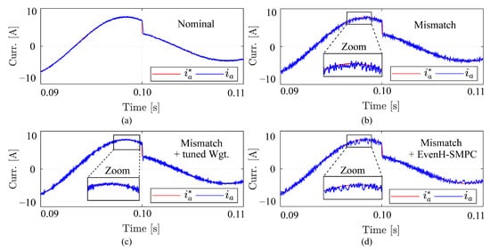
Figure 15.
Plots of grid current for a step in the amplitude of the reference current: (a) nominal parameter value, (b) 0.5L parameter mismatch, (c) 0.5L filter mismatch with optimally-tuned weighting factor, and (d) 0.5L filter mismatch with even-handed sequential MPC.
6.4. Performance Comparison
Table 5 summarizes the literature reporting the relative performance of different techniques for weighting factor design issues. Here, the classical heuristically-tuned weighting factor method is used as a reference for all other methods.
Table 5.
Summary of Different Methods.
Sequential MPC methods and online optimization methods are reported to demonstrate a measure of improved robustness against model parameter variations compared to classical MPC, while simplified MPC has identical robustness to classical MPC. Furthermore, the computational time required for sequential MPC methods and online optimization methods is typically higher than for classical MPC. Nonetheless, simplified MPC methods generally have lower computational time than classical MPC. Hence, in choosing a method for weighting factor design, several features need to be taken into consideration. First, where relative parametric robustness is of high priority, online weighting factor optimization and sequential MPC methods are recommended. The use of sequential MPC has a limitation in that it reduces optimal control performance [1]. Second, when lower computational time and hardware resources are a priority, simplified MPC becomes advantageous.
7. Conclusions
Weighting factor design for predictive control of power converters in renewable energy conversion, electric drives, smart/microgrids, etc., has faced asymmetry challenges, leading to cumbersome tuning requirements. For this reason, many researchers have resorted to suboptimal design methods which reduce the powerful optimal control potential of predictive control techniques. This article has presented a review of state-of-the-art methods in weighting factor design, showing that the choice of weighting factor techniques by researchers and practitioners can be guided by two main factors: first, where relative parametric robustness is of high priority, online weighting factor optimization and sequential MPC methods are superior; second, when lower computational time and low cost of hardware resources are a priority, the use of simplified MPC techniques becomes advantageous. The trend of development in optimal weighting factor design for predictive control of power electronics and motor drives indicates the potential for significant advancements thanks to emerging methods. Our future work will focus on hybrid design methods that combine features of two or more of the methods described above, e.g., sequential MPC with a computationally efficient selection of switching states.
Author Contributions
Conceptualization, Z.Z., O.B., and Y.Z.; methodology, O.B., Z.L.; software, Y.Z.; validation, O.B., Y.Z.; formal analysis, O.B.; investigation, Y.Z.; resources, Z.Z., Z.L.; data curation, Y.Z.; writing—original draft preparation, O.B., Y.Z.; writing—review and editing, Z.Z., Z.L.; visualization, O.B., Y.Z.; supervision, Z.Z., Z.L.; project administration, Z.Z.; funding acquisition, Z.Z. All authors have read and agreed to the published version of the manuscript.
Funding
This research was funded by National Key R&D Program of China (2022YFB4201700).
Data Availability Statement
Not applicable.
Conflicts of Interest
The authors declare no conflict of interest.
Nomenclature
| , , | State vector, output vector, switching state |
| , | Predictive and reference value of x |
| J | Cost function |
| Weighting factor | |
| P | Active power |
| Q | Reactive power |
| , | Generator and grid-side current vectors |
| Generator voltage vector | |
| Grid voltage vector | |
| , | Filter resistance and inductance |
References
- Karamanakos, P.; Geyer, T. Guidelines for the Design of Finite Control Set Model Predictive Controllers. IEEE Trans. Power Electron. 2020, 35, 7434–7450. [Google Scholar] [CrossRef]
- Vazquez, S.; Rodriguez, J.; Rivera, M.; Franquelo, L.G.; Norambuena, M. Model predictive control for power converters and drives: Advances and trends. IEEE Trans. Ind. Electron. 2016, 64, 935–947. [Google Scholar] [CrossRef]
- Liu, Y.; Shi, S.; Zhang, Z.; Di, Z.; Babayomi, O. Data-Driven Model Predictive Control for Wave Energy Converters Using Gaussian Process. Symmetry 2022, 14, 1284. [Google Scholar] [CrossRef]
- Heydari, R.; Dragicevic, T.; Blaabjerg, F. High-bandwidth secondary voltage and frequency control of VSC-Based AC microgrid. IEEE Trans. Power Electron. 2019, 34, 11320–11331. [Google Scholar] [CrossRef]
- Zhang, Y.; Liu, X.; Li, H.; Zhang, Z. A Model Independent Predictive Control of PMSG Wind Turbine Systems with a New Mechanism to Update Variables. Energies 2023, 16, 3764. [Google Scholar] [CrossRef]
- Babayomi, O.; Zhang, Z.; Dragicevic, T.; Hu, J.; Rodriguez, J. Smart grid evolution: Predictive control of distributed energy resources—A review. Int. J. Electr. Power Energy Syst. 2023, 147, 108812. [Google Scholar] [CrossRef]
- Cortes, P.; Kouro, S.; La Rocca, B.; Vargas, R.; Rodriguez, J.; Leon, J.I.; Vazquez, S.; Franquelo, L.G. Guidelines for weighting factors design in Model Predictive Control of power converters and drives. In Proceedings of the 2009 IEEE International Conference on Industrial Technology, Churchill, Australia, 10–13 February 2009; pp. 1–7. [Google Scholar] [CrossRef]
- Norambuena, M.; Rodriguez, J.; Zhang, Z.; Wang, F.; Garcia, C.; Kennel, R. A Very Simple Strategy for High-Quality Performance of AC Machines Using Model Predictive Control. IEEE Trans. Power Electron. 2019, 34, 794–800. [Google Scholar] [CrossRef]
- Babayomi, O.; Zhang, Z.; Li, Y.; Kennel, R. Adaptive Predictive Control with Neuro-Fuzzy Parameter Estimation for Microgrid Grid-Forming Converters. Sustainability 2021, 13, 7038. [Google Scholar] [CrossRef]
- Wang, Z.; Qu, Q.; Zhang, Y.; Min, Z. Model-Free Predictive Power Control for PWM Rectifiers under Asymmetrical Grids. Symmetry 2022, 14, 1224. [Google Scholar] [CrossRef]
- Zhang, Z.; Li, Z.; Kazmierkowski, M.P.; Rodriguez, J.; Kennel, R. Robust Predictive Control of Three-Level NPC Back-to-Back Power Converter PMSG Wind Turbine Systems with Revised Predictions. IEEE Trans. Power Electron. 2018, 33, 9588–9598. [Google Scholar] [CrossRef]
- Zhang, J.; Li, L.; Dorrell, D.G.; Norambuena, M.; Rodriguez, J. Predictive Voltage Control of Direct Matrix Converters with Improved Output Voltage for Renewable Distributed Generation. IEEE J. Emerg. Sel. Top. Power Electron. 2019, 7, 296–308. [Google Scholar] [CrossRef]
- Elmorshedy, M.F.; Xu, W.; Allam, S.M.; Rodriguez, J.; Garcia, C. MTPA-Based Finite-Set Model Predictive Control Without Weighting Factors for Linear Induction Machine. IEEE Trans. Ind. Electron. 2021, 68, 2034–2047. [Google Scholar] [CrossRef]
- Shadmand, M.B.; Jain, S.; Balog, R.S. Autotuning Technique for the Cost Function Weight Factors in Model Predictive Control for Power Electronic Interfaces. IEEE J. Emerg. Sel. Top. Power Electron. 2019, 7, 1408–1420. [Google Scholar] [CrossRef]
- Zaouche, K.; Benmerabet, S.M.; Talha, A.; Berkouk, E.M. Finite-Set Model Predictive Control of an Asymmetric Cascaded H-bridge photovoltaic inverter. Appl. Surf. Sci. 2019, 474, 102–110. [Google Scholar] [CrossRef]
- Guazzelli, P.R.U.; Pereira, W.C.d.A.; Oliveira, C.M.R.d.; Castro, A.G.D.; Aguiar, M.L.D. Weighting Factors Optimization of Predictive Torque Control of Induction Motor by Multiobjective Genetic Algorithm. IEEE Trans. Power Electron. 2019, 34, 6628–6638. [Google Scholar] [CrossRef]
- Novak, M.; Xie, H.; Dragicevic, T.; Wang, F.; Rodriguez, J.; Blaabjerg, F. Optimal Cost Function Parameter Design in Predictive Torque Control (PTC) Using Artificial Neural Networks (ANN). IEEE Trans. Ind. Electron. 2020, 68, 7309–7319. [Google Scholar] [CrossRef]
- Kim, S.; Jang, Y.; Kim, R. Modeling and Hierarchical Structure Based Model Predictive Control of Cascaded Flying Capacitor Bridge Multilevel Converter for Active Front-End Rectifier in Solid-State Transformer. IEEE Trans. Ind. Electron. 2019, 66, 6560–6569. [Google Scholar] [CrossRef]
- Wu, W.; Wang, D.; Liu, L. A Multi-Layer Sequential Model Predictive Control of Three-Phase Two-Leg Seven-Level T-Type Nested Neutral Point Clamped Converter Without Weighting Factors. IEEE Access 2019, 7, 162735–162746. [Google Scholar] [CrossRef]
- Cui, Z.; Zhang, Z.; Dragicevic, T.; Rodríguez, J. Dynamic Sequential Model Predictive Control of Three-Level NPC Back-to-Back Power Converter PMSG Wind Turbine Systems. In Proceedings of the IECON 2020 the 46th Annual Conference of the IEEE Industrial Electronics Society, Singapore, 18–21 October 2020; pp. 3206–3211. [Google Scholar] [CrossRef]
- Jlassi, I.; Cardoso, A.J.M. Enhanced and Computationally Efficient Model Predictive Flux and Power Control of PMSG Drives for Wind Turbine Applications. IEEE Trans. Ind. Electron. 2020, 68, 6574–6583. [Google Scholar] [CrossRef]
- Pei, W.; Zhang, Q.; Li, Y. Efficiency Optimization Strategy of Permanent Magnet Synchronous Motor for Electric Vehicles Based on Energy Balance. Symmetry 2022, 14, 164. [Google Scholar] [CrossRef]
- Lin, X.; Huang, W.; Jiang, W.; Zhao, Y.; Zhu, S. Predictive Torque Control for PMSM Based on Weighting Factor Elimination and Fast Voltage Vector Selection. IEEE J. Emerg. Sel. Top. Power Electron. 2020, 8, 3736–3750. [Google Scholar] [CrossRef]
- Luo, Y.; Liu, C. A Flux Constrained Predictive Control for a Six-Phase PMSM Motor with Lower Complexity. IEEE Trans. Ind. Electron. 2019, 66, 5081–5093. [Google Scholar] [CrossRef]
- Easley, M.; Jain, S.; Shadmand, M.; Abu-Rub, H. Autonomous Model Predictive Controlled Smart Inverter With Proactive Grid Fault Ride-Through Capability. IEEE Trans. Energy Convers. 2020, 35, 1825–1836. [Google Scholar] [CrossRef]
- Guler, N.; Biricik, S.; Bayhan, S.; Komurcugil, H. Model Predictive Control of DC–DC SEPIC Converters With Autotuning Weighting Factor. IEEE Trans. Ind. Electron. 2021, 68, 9433–9443. [Google Scholar] [CrossRef]
- Xiao, D.; Akter, M.P.; Alam, K.; Dutta, R.; Mekhilef, S.; Rahman, M.F. Cascaded Predictive Flux Control for a 3-L Active NPC Fed IM Drives Without Weighting Factor. IEEE Trans. Energy Convers. 2021, 36, 1797–1807. [Google Scholar] [CrossRef]
- Musunuru, N.S.P.; Srinivas, S. Cascaded Predictive Control of a Single Power Supply driven Four-level Open-end Winding Induction motor drive without weighting factors. IEEE J. Emerg. Sel. Top. Power Electron. 2020, 9, 2858–2867. [Google Scholar] [CrossRef]
- Davari, S.A.; Norambuena, M.; Nekoukar, V.; Garcia, C.; Rodriguez, J. Even-Handed Sequential Predictive Torque and Flux Control. IEEE Trans. Ind. Electron. 2020, 67, 7334–7342. [Google Scholar] [CrossRef]
- Kusuma, E.; Eswar, K.M.R.; Kumar, T.V. An Effective Predictive Torque Control Scheme for PMSM Drive without Involvement of Weighting Factors. IEEE J. Emerg. Sel. Top. Power Electron. 2020, 9, 2685–2697. [Google Scholar] [CrossRef]
- Bakeer, A.; Magdy, G.; Chub, A.; Vinnikov, D. Predictive control based on ranking multi-objective optimization approach for quasi Z-source inverter. CSEE J. Power Energy Syst. 2020, 7, 1152–1160. [Google Scholar] [CrossRef]
- Zhang, Y.; Zhang, B.; Yang, H.; Norambuena, M.; Rodriguez, J. Generalized Sequential Model Predictive Control of IM Drives With Field-Weakening Ability. IEEE Trans. Power Electron. 2019, 34, 8944–8955. [Google Scholar] [CrossRef]
- Li, Y.H.; Wu, T.X.; Zhai, D.W.; Zhao, C.H.; Zhou, Y.F.; Qin, Y.G.; Su, J.S.; Qin, H. Hybrid Decision Based on DNN and DTC for Model Predictive Torque Control of PMSM. Symmetry 2022, 14, 693. [Google Scholar] [CrossRef]
- Xie, H.; Du, J.; Ke, D.; He, Y.; Wang, F.; Hackl, C.; Rodríguez, J.; Kennel, R. Multistep Model Predictive Control for Electrical Drives—A Fast Quadratic Programming Solution. Symmetry 2022, 14, 626. [Google Scholar] [CrossRef]
- Meesala, R.E.K.; Kunisetti, V.P.K.; Thippiripati, V.K. Enhanced Predictive Torque Control for Open End Winding Induction Motor Drive Without Weighting Factor Assignment. IEEE Trans. Power Electron. 2019, 34, 503–513. [Google Scholar] [CrossRef]
- Yang, Y.; Wen, H.; Fan, M.; He, L.; Xie, M.; Chen, R.; Norambuena, M.; Rodríguez, J. Multiple-Voltage-Vector Model Predictive Control With Reduced Complexity for Multilevel Inverters. IEEE Trans. Transp. Electrif. 2020, 6, 105–117. [Google Scholar] [CrossRef]
- Liu, T.; Chen, A.; Qin, C.; Chen, J.; Li, X. Double Vector Model Predictive Control to Reduce Common-Mode Voltage without Weighting Factors for Three-Level Inverters. IEEE Trans. Ind. Electron. 2020, 67, 8980–8990. [Google Scholar] [CrossRef]
- Moon, J.W.; Gwon, J.S.; Park, J.W.; Kang, D.W.; Kim, J.M. Model Predictive Control With a Reduced Number of Considered States in a Modular Multilevel Converter for HVDC System. IEEE Trans. Power Deliv. 2015, 30, 608–617. [Google Scholar] [CrossRef]
- Siami, M.; Arab Khaburi, D.; Rodriguez, J. Simplified Finite Control Set-Model Predictive Control for Matrix Converter-Fed PMSM Drives. IEEE Trans. Power Electron. 2018, 33, 2438–2446. [Google Scholar] [CrossRef]
- Wu, X.; Song, W.; Xue, C. Low-Complexity Model Predictive Torque Control Method Without Weighting Factor for Five-Phase PMSM Based on Hysteresis Comparators. IEEE J. Emerg. Sel. Top. Power Electron. 2018, 6, 1650–1661. [Google Scholar] [CrossRef]
- Davari, S.A.; Rodriguez, J. Predictive Direct Voltage Control of Induction Motor With Mechanical Model Consideration for Sensorless Applications. IEEE J. Emerg. Sel. Top. Power Electron. 2018, 6, 1990–2000. [Google Scholar] [CrossRef]
- Xu, Y.; He, Y.; Li, S. Logical Operation-Based Model Predictive Control for Quasi-Z-Source Inverter without Weighting Factor. IEEE J. Emerg. Sel. Top. Power Electron. 2021, 9, 1039–1051. [Google Scholar] [CrossRef]
- Jun, E.S.; Nguyen, M.H.; Kwak, S.S. Model Predictive Control Method with NP Voltage Balance by Offset Voltage Injection for Three-Phase Three-Level NPC Inverter. IEEE Access 2020, 8, 172175–172195. [Google Scholar] [CrossRef]
- Liu, X.; Wang, D.; Peng, Z. A Computationally Efficient FCS-MPC Method Without Weighting Factors for NNPCs With Optimal Duty Cycle Control. IEEE/ASME Trans. Mechatron. 2018, 23, 2503–2514. [Google Scholar] [CrossRef]
- Jin, Y.; Xiao, Q.; Jia, H.; Mu, Y.; Ji, Y.; Dragieevic, T.; Teodorescu, R.; Blaabjerg, F. A Novel Sliding-Discrete-Control-Set Modulated Model Predictive Control for Modular Multilevel Converter. IEEE Access 2021, 9, 10316–10327. [Google Scholar] [CrossRef]
- Wang, J.; Liu, X.; Xiao, Q.; Zhou, D.; Qiu, H.; Tang, Y. Modulated Model Predictive Control for Modular Multilevel Converters With Easy Implementation and Enhanced Steady-State Performance. IEEE Trans. Power Electron. 2020, 35, 9107–9118. [Google Scholar] [CrossRef]
- Kaymanesh, A.; Chandra, A.; Al-Haddad, K. Model Predictive Control of MPUC7-Based STATCOM Using Autotuned Weighting Factors. IEEE Trans. Ind. Electron. 2021, 69, 2447–2458. [Google Scholar] [CrossRef]
- Yang, Y.; Pan, J.; Wen, H.; Zhang, X.; Wang, Y.; Perdikakis, W. Model Predictive Control with Auto-tuning Weighting Factors for Single-phase Six-Level Hybrid-Clamped Converters. IEEE Trans. Ind. Electron. 2020, 68, 7946–7956. [Google Scholar] [CrossRef]
- Davari, S.A.; Nekoukar, V.; Garcia, C.; Rodriguez, J. Online Weighting Factor Optimization by Simplified Simulated Annealing for Finite Set Predictive Control. IEEE Trans. Ind. Inform. 2021, 17, 31–40. [Google Scholar] [CrossRef]
- Bhowate, A.; Aware, M.; Sharma, S. Predictive Torque Control With Online Weighting Factor Computation Technique to Improve Performance of Induction Motor Drive in Low Speed Region. IEEE Access 2019, 7, 42309–42321. [Google Scholar] [CrossRef]
- Gong, C.; Hu, Y.; Ma, M.; Gao, J.; Shen, K. Novel Analytical Weighting Factor Tuning Strategy Based on State Normalization and Variable Sensitivity Balance for PMSM FCS-MPTC. IEEE/ASME Trans. Mechatron. 2020, 25, 1690–1694. [Google Scholar] [CrossRef]
- Caseiro, L.M.; Mendes, A.M.; Cruz, S.M. Dynamically Weighted Optimal Switching Vector Model Predictive Control of Power Converters. IEEE Trans. Ind. Electron. 2019, 66, 1235–1245. [Google Scholar] [CrossRef]
- Babaie, M.; Mehrasa, M.; Sharifzadeh, M.; Al-Haddad, K. Floating Weighting Factors ANN-MPC Based on Lyapunov Stability for Seven-Level Modified PUC Active Rectifier. IEEE Trans. Ind. Electron. 2021, 69, 387–398. [Google Scholar] [CrossRef]
- Machado, O.; Martín, P.; Rodríguez, F.J.; Bueno, E.J. A Neural Network-Based Dynamic Cost Function for the Implementation of a Predictive Current Controller. IEEE Trans. Ind. Inform. 2017, 13, 2946–2955. [Google Scholar] [CrossRef]
- Dragicevic, T.; Novak, M. Weighting Factor Design in Model Predictive Control of Power Electronic Converters: An Artificial Neural Network Approach. IEEE Trans. Ind. Electron. 2019, 66, 8870–8880. [Google Scholar] [CrossRef]
- Wang, S.; Dehghanian, P.; Alhazmi, M.; Nazemi, M. Advanced control solutions for enhanced resilience of modern power-electronic-interfaced distribution systems. J. Mod. Power Syst. Clean Energy 2019, 7, 716–730. [Google Scholar] [CrossRef]
- Rojas, C.A.; Rodriguez, J.R.; Kouro, S.; Villarroel, F. Multiobjective Fuzzy-Decision-Making Predictive Torque Control for an Induction Motor Drive. IEEE Trans. Power Electron. 2017, 32, 6245–6260. [Google Scholar] [CrossRef]
- Karamanakos, P.; Liegmann, E.; Geyer, T.; Kennel, R. Model Predictive Control of Power Electronic Systems: Methods, Results, and Challenges. IEEE Open J. Ind. Appl. 2020, 1, 95–114. [Google Scholar] [CrossRef]
- Valencia, D.F.; Tarvirdilu-Asl, R.; Garcia, C.; Rodriguez, J.; Emadi, A. A Review of Predictive Control Techniques for Switched Reluctance Machine Drives. Part I: Fundamentals and Current Control. IEEE Trans. Energy Convers. 2021, 36, 1313–1322. [Google Scholar] [CrossRef]
- Valencia, D.F.; Tarvirdilu-Asl, R.; Garcia, C.; Rodriguez, J.; Emadi, A. A Review of Predictive Control Techniques for Switched Reluctance Machine Drives. Part II: Torque Control, Assessment and Challenges. IEEE Trans. Energy Convers. 2021, 36, 1323–1335. [Google Scholar] [CrossRef]
- Dong, Z.; Zhang, Z.; Li, Z.; Li, X.; Qin, J.; Liang, C.; Han, M.; Yin, Y.; Bai, J.; Wang, C.; et al. A Survey of Battery–Supercapacitor Hybrid Energy Storage Systems: Concept, Topology, Control and Application. Symmetry 2022, 14, 1085. [Google Scholar] [CrossRef]
- Rodriguez, J.; Garcia, C.; Mora, A.; Flores-Bahamonde, F.; Acuna, P.; Novak, M.; Zhang, Y.; Tarisciotti, L.; Davari, S.A.; Zhang, Z.; et al. Latest Advances of Model Predictive Control in Electrical Drives—Part I: Basic Concepts and Advanced Strategies. IEEE Trans. Power Electron. 2022, 37, 3927–3942. [Google Scholar] [CrossRef]
- Rodriguez, J.; Garcia, C.; Mora, A.; Davari, S.A.; Rodas, J.; Valencia, D.F.; Elmorshedy, M.; Wang, F.; Zuo, K.; Tarisciotti, L.; et al. Latest Advances of Model Predictive Control in Electrical Drives—Part II: Applications and Benchmarking with Classical Control Methods. IEEE Trans. Power Electron. 2022, 37, 5047–5061. [Google Scholar] [CrossRef]
- Babayomi, O.; Li, Z.; Zhang, Z.; Sun, Y.; Dragicevic, T.; Rodriguez, J. The Role of Model Predictive Control in Microgrid Power Quality—A Survey. In Proceedings of the 2020 IEEE 11th International Symposium on Power Electronics for Distributed Generation Systems (PEDG), Dubrovnik, Croatia, 28 September–1 October 2020; pp. 340–345. [Google Scholar] [CrossRef]
- Razmi, D.; Babayomi, O.; Davari, A.; Rahimi, T.; Miao, Y.; Zhang, Z. Review of Model Predictive Control of Distributed Energy Resources in Microgrids. Symmetry 2022, 14, 1735. [Google Scholar] [CrossRef]
- Chen, H.; Zhang, Z.; Karamanakos, P.; Rodriguez, J. Digital Twin Techniques for Power Electronics-Based Energy Conversion Systems: A Survey of Concepts, Application Scenarios, Future Challenges, and Trends. IEEE Ind. Electron. Mag. 2022, accepted. [Google Scholar] [CrossRef]
- Geyer, T. Model Predictive Control of High Power Converters and Industrial Drives; John Wiley & Sons: Hoboken, NJ, USA, 2016. [Google Scholar]
- Zhang, Z.; Fang, H.; Gao, F.; Rodríguez, J.; Kennel, R. Multiple-Vector Model Predictive Power Control for Grid-Tied Wind Turbine System With Enhanced Steady-State Control Performance. IEEE Trans. Ind. Electron. 2017, 64, 6287–6298. [Google Scholar] [CrossRef]
- Kang, S.W.; Soh, J.H.; Kim, R.Y. Symmetrical Three-Vector-Based Model Predictive Control With Deadbeat Solution for IPMSM in Rotating Reference Frame. IEEE Trans. Ind. Electron. 2020, 67, 159–168. [Google Scholar] [CrossRef]
- Han, J.; Zhao, P.; Yao, G.; Chen, H.; Wang, Y.; Benbouzid, M.; Tang, T. Model predictive current control of asymmetrical hybrid cascaded multilevel inverter. J. Power Electron. 2022, 22, 580–592. [Google Scholar] [CrossRef]
- Yu, X.; Yang, Y.; Xu, L.; Ke, D.; Zhang, Z.; Wang, F. Luenberger Disturbance Observer-Based Deadbeat Predictive Control for Interleaved Boost Converter. Symmetry 2022, 14, 924. [Google Scholar] [CrossRef]
- Eswar, K.M.R.; Kumar, K.V.P.; Kumar, T.V. A Simplified Predictive Torque Control Scheme for Open-End Winding Induction Motor Drive. IEEE J. Emerg. Sel. Top. Power Electron. 2019, 7, 1162–1172. [Google Scholar] [CrossRef]
- Xu, H.; Yu, C.; Liu, C.; Wang, Q.; Liu, F.; Li, F. An Improved Virtual Capacitor Algorithm for Reactive Power Sharing in Multi-Paralleled Distributed Generators. IEEE Trans. Power Electron. 2019, 34, 10786–10795. [Google Scholar] [CrossRef]
- Zhao, S.; Blaabjerg, F.; Wang, H. An Overview of Artificial Intelligence Applications for Power Electronics. IEEE Trans. Power Electron. 2021, 36, 4633–4658. [Google Scholar] [CrossRef]
- Geyer, T. Algebraic Tuning Guidelines for Model Predictive Torque and Flux Control. IEEE Trans. Ind. Appl. 2018, 54, 4464–4475. [Google Scholar] [CrossRef]
- Zhang, Z.; Hackl, C.M.; Kennel, R. Computationally Efficient DMPC for Three-Level NPC Back-to-Back Converters in Wind Turbine Systems With PMSG. IEEE Trans. Power Electron. 2017, 32, 8018–8034. [Google Scholar] [CrossRef]
- Cui, Z.; Zhang, Z.; Yang, Q.; Kennel, R. Cascaded Model Predictive Control of Three-Level NPC Back-to-Back Power Converter PMSG Wind Turbine Systems. In Proceedings of the 2018 IEEE International Power Electronics and Application Conference and Exposition (PEAC), Shenzhen, China, 4–7 November 2018; pp. 1–6. [Google Scholar] [CrossRef]
- Li, Y.; Zhang, Z.; Kazmierkowski, M.P. Cascaded Predictive Control for Three-Level NPC Power Converter Fed Induction Machine Drives Without Weighting Factors. In Proceedings of the 2018 IEEE International Power Electronics and Application Conference and Exposition (PEAC), Shenzhen, China, 4–7 November 2018; pp. 1–5. [Google Scholar] [CrossRef]


Disclaimer/Publisher’s Note: The statements, opinions and data contained in all publications are solely those of the individual author(s) and contributor(s) and not of MDPI and/or the editor(s). MDPI and/or the editor(s) disclaim responsibility for any injury to people or property resulting from any ideas, methods, instructions or products referred to in the content. |
© 2023 by the authors. Licensee MDPI, Basel, Switzerland. This article is an open access article distributed under the terms and conditions of the Creative Commons Attribution (CC BY) license (https://creativecommons.org/licenses/by/4.0/).