Article

Grid Harmonics Suppression for Three Phase Dual-Frequency Grid-Connected Inverter Based on Feedforward Compensation

1
School of Automation and Electrical Engineering, University of Science and Technology Beijing, Beijing 100083, China
2
College of Electrical and Control Engineering, North China University of Technology, Beijing 100144, China
*
Author to whom correspondence should be addressed.
Symmetry 2023, 15(8), 1517; https://doi.org/10.3390/sym15081517
Submission received: 16 June 2023 / Revised: 28 July 2023 / Accepted: 30 July 2023 / Published: 1 August 2023
(This article belongs to the Section Engineering and Materials)

Abstract

:
Using a low pulse ratio, the electromagnetic interference and switching loss of an inverter can be effectively reduced, particularly in high-power applications. However, due to variations in grid impedance, it is a challenging task to achieve stable operation of an LCL-type grid-connected inverter (GCI) using the active damping method with low pulse ratio. Thus, a novel three-phase dual-frequency GCI is presented to ensure the symmetry of the output power and the stable operation of the system address stability issues. The proposed inverter topology in this article is composed of two inverters in parallel, which are, respectively, a power inverter unit (PIU) and an auxiliary harmonic elimination unit (AHEU). To reduce the switching loss and improve the inverter efficiency, the switching frequency of the PIU is relatively low, injecting current into the grid. Moreover, the feedforward compensation method is used in AHEU. AHEU operates at high switching frequency to generate a current component that is symmetrical with the ripple com-ponent, improving the power quality, without extracting the current harmonic as the current reference. The operating principle of feedforward compensation is explained, and a proper parameter design procedure is presented in this paper. Since L filters are used for the proposed inverter, the system can operate stably where the ratio of switching frequency to fundamental frequency is low. A 10 kW laboratory prototype was built. The experimental results showed that the grid current ripple could be effectively eliminated and the THD of the grid current was 3.01%. The proposed inverter has good stability in a weak grid, and the efficiency of the proposed inverter is 95.98% at rated current, which is 0.81% higher than the traditional GCI, effectively increasing the efficiency of the system.

1. Introduction

In recent years, photovoltaics has become one of the most promising energy sources due to its ease of installation, environmental friendliness and low maintenance costs [1,2,3,4]. As a result, solar photovoltaic power generation systems have attracted a lot of attention. As an interface between generation systems and the grid, the grid-connected inverter (GCI) can inject high quality power into the grid.
To improve the quality of grid current, the inverter is connected to the grid through various filters, such as L, LC and LCL filters [5]. The L filter has the simplest structure and high reliability but only −20 dB/dec attenuation. As a result, using an L filter, a high switching frequency is needed by the inverter, or the inductance must have a large value to comply with grid standards such as IEEE929-2000 and IEEE 519 [6,7]. It is not helpful for improving system efficiency and power density [8,9]. The LC filter is used to increase the harmonic attenuation which has −40 dB/dec attenuation rate, but it is not usually used in GCIs, because the resonance frequency varies with the change in the grid inductance. Compared with the previous two, the LCL filter is advantageous with a harmonic attenuation rate of −60 dB/dec [10]. Therefore, the LCL filter is an attractive solution in practical applications.
In [11], an algorithm for LCL filter design was implemented by analyzing the interrelationships between parameters. Nevertheless, various constraints must be considered to calculate the range of each parameter, such as the reactive power, grid-connected current harmonics, and inductor current ripple [12,13,14]. Inevitably, the design of the three-order LCL filter is extremely complex. It is worth noting that, even if the LCL filter is designed with various constraints, there are stability problems in the GCI due to the inherent resonance phenomenon of the LCL filter [15,16,17]. Generally, active damping solutions are used to suppress the resonance of the LCL filter, which only change the control loops without damping resistance. In [18], a filter-based damping method was proposed to prevent the resonance without additional sensors. Nevertheless, the variation in LCL filter resonance frequency had a significant influence on the stability. To increase the robustness, an additional state variable could be fed back. However, the digital control delay is generated by algorithm execution, which affects the characteristics of the virtual resistor. In addition, for high-power voltage source inverters (VSIs) with a low switching frequency, the ratio of switching to fundamental frequency is generally small [19,20]. To improve stability, the crossover frequency of the filters was supposed to be much lower than the switching harmonics, but higher than the current control bandwidth [14,21,22,23]. It brings great challenges for the design of LCL filters [24].
To solve the above-mentioned problems, a novel single-phase inverter was proposed in [25,26,27], which included two converters operating at different switching frequencies. One converter operated at low pulse ratio to inject current into the grid, while the other converter eliminated the grid current ripple with a high pulse ratio, using the feedforward compensation method. Thus, compared to the LCL inverter, the proposed inverter was highly robust concerning changes in grid impedance and grid voltage harmonics without the need for high current sampling accuracy. Furthermore, the power loss generated by the converter operating at a low switching frequency was significantly reduced. Accordingly, the efficiency of the inverter near the rated power was improved. However, the above research was aimed at single-phase GCI. Since three-phase systems have lower current per phase and lower hardware requirements than single-phase systems at the same power level, in high-power applications, three-phase GCIs are more appropriate. It is expected that the idea of the dual-frequency inverter is more suitable for the application of a three-phase inverter due to its lower switching losses.
In this paper, the topology of the three-phase GCI is proposed, the harmonic elimination principle is analyzed, and the control scheme based on feedforward compensation is proposed. In addition, the inverter parameter design method is proposed, including the inductance of the power inverter unit (PIU), the dc-link voltage of the auxiliary harmonic elimination unit (AHEU) and the inductance of the AHEU. The main contributions of this paper are given as follows:
  • The feedforward compensation method is used to control the AHEU to generate the output current which is symmetric with the current ripple of the PIU. Compared with an active power filter, it avoids extracting harmonics as current reference, which reduces the requirements for sampling accuracy and current control bandwidth.
  • A parameter design method for switching frequency and filter inductance is proposed considering system efficiency, and the influence of switching frequency and inductance changes on power loss is discussed. The experimental results verify that the proposed inverter has a significant improvement in efficiency.
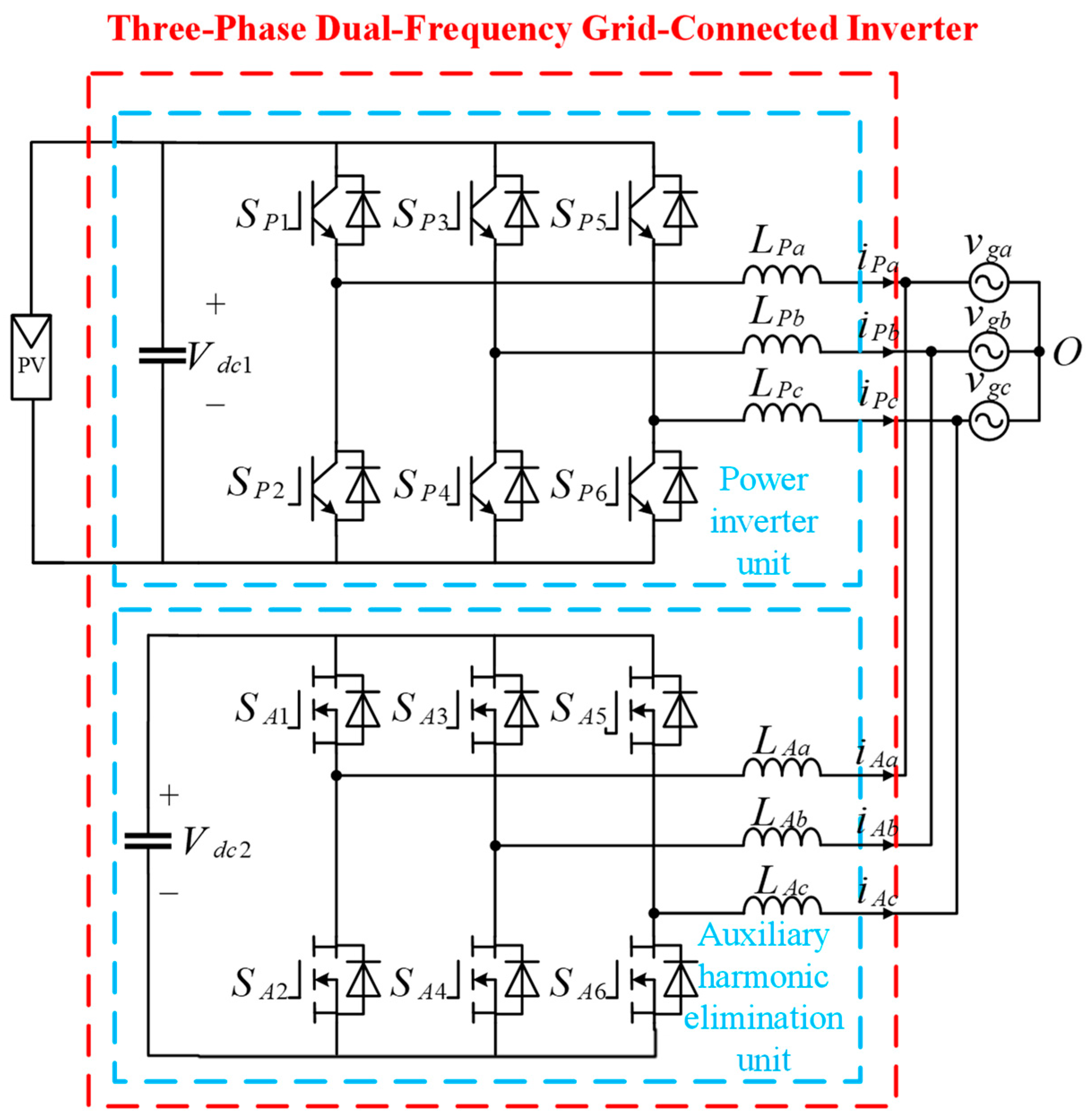
  • A three-phase dual-frequency GCI topology is presented which consists of PIU and AHEU. The PIU operates at a low pulse ratio to reduce the switching loss, and electric energy is transmitted to the power grid by PIU. The AHEU operates at high switching frequency to improve power quality. Furthermore, the stability of the system under a weak grid is analyzed; the proposed inverter can address the stability issue of the LCL filter in low pulse-ratio VSIs with high power in weak grid.
The remainder of the paper is organized as follows. The topology and harmonic elimination principle is introduced in Section 2. In Section 3, a detailed introduction is given to the design method of the proposed inverter parameters. In Section 4, the analysis of stability under weak grid conditions is presented. In Section 5, the control scheme of the PIU and AHEU is presented, based on feedforward compensation. Section 6 presents the experiment and simulation results and verifies the effectiveness of the theory and prototype. In the final section, the conclusion is given.

2. Proposed Inverter’s Topology and Principle of Operation

2.1. Proposed Topology

As shown in Figure 1, the main circuit topology of the proposed inverter is presented, which consists of a PIU and an AHEU. Here, Vdc1 and Vdc2 are the dc-links of the PIU and AHEU, vgn is the grid voltage of phase n, n = a, b, c. The filters of PIU and AHEU are LPn and LAn, respectively. To reduce the switching loss and improve the inverter efficiency, the switching frequency of the PIU is relatively low, injecting current into the grid. The AHEU generates the output current which is symmetric with the current ripple of the PIU. In addition, it operates at high switching frequency; hence, its current ripple is very low. As shown in Figure 1, the grid current is the sum of the AHEU current iAn and the PIU current iPn in each phase. So, the grid current does not include the current ripple generated by the PIU current, which guarantees the quality of the grid current.
Since the operating current of the AHEU is relatively low, the cost of switching elements and inductors is much lower than that of the PIU. Moreover, the proposed inverter does not primarily rely on filters to suppress ripple, indicating the total inductance can be reduced. Although the output voltage of the power inverter unit is used in the control loop of the AHEU, it can be estimated by drive signals without an additional voltage sampling circuit. The topology of the proposed inverter is similar to an active power filter [28]; thus, there has not been a significant increase in hardware costs, compared with existing solutions. In addition, for the proposed inverter, extracting harmonics as current reference is avoided, which reduces the requirements for sampling accuracy. Therefore, although more devices are used in the proposed inverter, the cost will not significantly increase.
If the common dc-link is shared by the PIU and the AHEU, the circulating current is generated due to the differences in the two units of the switching frequency and other parameters [29]. The circulating current can increase power loss, distort the harmonics of the output current and reduce the useful life of inverters [30,31]. According to [30], circulating current problems are more severe in space-vector modulation-controlled inverters. However, the circulating current is blocked with an isolated dc-link for the proposed inverter, so there is no circulating current with the traditional space-vector modulation. In order to maintain the dc-link voltage of the AHEU Vdc2, the voltage loop is used in the control strategy.
L filters are used in the proposed inverter, as shown in Figure 1. Compared with an LCL filter, there is no inherent filter resonance for an L filter. As a result, the system stability is greatly enhanced. Additionally, the system parameter design and the current control strategy can be simplified significantly.

2.2. Proposed Inverter’s Principle of Harmonic Elimination

In Figure 2, for the proposed inverter, neglecting the series resistances, the voltages uP and uA can be expressed as
u P = u P L + v G
u A = u A L + v G
where u P = u P a u P b u P c T and u A = u A a u A b u A c T are the output voltages of PIU and AHEU, u P L = u P L a u P L b u P L c T and u A L = u A L a u A L b u A L c T are the voltages across the LP and LA, v g = v g a v g b v g c T are the grid voltages. The grid currents can be expressed as
i g = i P + i A
where i g = i g a i g b i g c T , i P = i P a i P b i P c T and i A = i A a i A b i A c T are the output currents of inverter in PIU and AHEU, respectively.
Since the PIU operates at a low pulse ratio, the output currents iP contain obvious current ripples. Then, iP can be resolved into fundamental component iPf and current ripple component iPs, so iP can be expressed as
i P = i P f + i P s
Similarly, uPL can be resolved into fundamental component uPf and switching harmonic component uPs, i.e.,
u P L = u P f + u P s
In the steady state, iPf can be expressed as
i P f = 1 L P u P f d t
Correspondingly, iPs can be derived using (1), (4), (5) and (6), as follows
i P s = 1 L P u P s d t = 1 L P u P v g L P d i P f d t d t
Then, from (3) and (7), the expression of grid current ig can be obtained as
i g = i P f + i A + 1 L P u P v g L P d i P f d t d t
Since the switching frequency of the AHEU is far above than that of the PIU, the influence of high-frequency voltage harmonics on the output currents of the proposed inverter can be ignored.
To suppress current ripple, the ripple compensation voltage uE is designed as
u E = L A L P u P v g L P d i P f d t + v g
From Figure 2, the iA can be expressed as
i A = 1 L A u E v g d t
Substitute (10) and (9) into (8), the grid current ig is
i g = i P f
From (11), the current ripple component in iPs is completely eliminated by iA. Obviously, the resonance phenomenon of the LCL-type GCI can be eliminated by the proposed inverter. In consequence, the system stability can be improved, and the control algorithm is simplified significantly.

3. Proposed Inverter’s Parameter Design

3.1. Design of the PIU Filter Inductance LP

Due to low switching frequency of the PIU, its current ripple is significant compared with rated current. When the current ripple increases, it leads to an increase in the switching stress of the power semiconductor devices and the inductor loss, which can reduce the efficiency of the inverter [32]. Accordingly, it is essential to limit the current ripple. In general, the current ripple is limited to no more than 20% of the grid current amplitude Igm. However, the amplitude of the current ripple is subjected to the filter inductance of the PIU. Therefore, the lower limit of the filter inductance LP can be determined as follows
L P = V d c 1 20 % × 4 3 I g _ p e a k f P
where the fP is the switching frequency of the PIU.

3.2. Design of the AHEU Filter Inductance LA

The series resistances of the filter inductor LA can be neglected. For the AHEU, the transfer function from iA to uA is given as
i A ( s ) u A ( s ) = 1 L A s
In this paper, the magnitude of 1/(LAS) <−50 dB at the switching frequency of the AHEU must be satisfied. Consequently, LA can be obtained as
L A = 10 2.5 2 π f A

3.3. Design of the DC-Link Voltage of the AHEU

In order that the current ripple can be eliminated by the output current of the AHEU completely, the dc-side voltage Vdc2 of the AHEU should be larger than a certain voltage. In this paper, Vdc2 is maintained at its reference Vdc2* by the voltage control loop.
vg and ig can be expressed as
v g = v g a v g b v g c = V g m cos ω g t V g m cos ( ω g t + 2 π 3 ) V g m cos ( ω g t + 4 π 3 )
i g = i g a i g b i g c = I g m cos ω g t I g m cos ( ω g t + 2 π 3 ) I g m cos ( ω g t + 4 π 3 )
where Vgm and Igm are the grid voltage and current amplitude, respectively, ωg is the angular frequency of the grid. According to (9) and (11), the ripple compensation voltage uE can be expressed as
u E = V m cos ω g t + φ L A L P u P a V m cos ω g t + 2 π 3 + φ L A L P u P b V m cos ω g t + 4 π 3 + φ L A L P u P c
where
V m = 1 + L A / L P V g m 2 + L A ω g I g m 2
φ = tan 1 L A ω g I g m 1 + L A / L P V g m
Considering the different switch states of the PIU, the peak value of uE can be expressed as
u E m V m + 2 L A 3 L P V d c 1
According to the space vector pulse width modulation (SVPWM) technique, the dc-link voltage of the AHEU Vdc2 should satisfy
V d c 2 * 3 u E m

3.4. Design of the Switching Frequency

The switching frequency of the two units is selected by combining the power loss and dead time of the inverter. The switching loss of the power electronic devices is increased with increasing the switching frequency, but the inductance of the filter decreases correspondingly with increasing the switching frequency, which may reduce the power loss on the inductance. Therefore, it is necessary to comprehensively consider the impact of switching frequency on switch loss and filter loss.
In Figure 3, the power loss at different switching frequencies of the PIU when the switching frequency of AHEU fA is 60 kHz is shown. It can be seen that the power loss of the system is the lowest at about 6 kHz. However, the switching frequency of the GCI is usually set below 3 kHz in high-power applications. In order to simulate a high-power GCI and analyze the stability under low switching frequency, combined with the loss analysis results, a switching frequency of the PIU fP of 2.5 kHz was chosen in this paper.
Figure 4 shows the loss curve of the system at different switching frequencies of AHEU when the fP was 2.5 kHz. From Figure 4, it can be seen that the change in fA had no significant impact on the system loss, because the output currents of the AHEU were small. With increasing the fA, the loss of the system was gradually decreased. When the switching frequency was higher than 60 kHz, the total loss of system hardly changed. Considering the dead time effect of the power switching device, the fA is 60 kHz.

4. Stability Analysis of Proposed Inverter

The current control block diagram of the PIU is shown in Figure 5. From Figure 5, iPref is the current reference. GIP(s) is the current controller. The i P is the error between iPref and iP. GDP(s) is the system delay. KPWM is the gain of the inverter, which is equal to Vdc1/ 3 , GFP(s) is the grid voltage feedforward coefficient, which is equal to 1/ KPWM. Zg is the grid impedance. uPCC is the voltage at the point of common coupling (PCC). The grid equivalent resistance can provide certain damping, which can improve the stability of the system. In order to discuss the most unstable conditions, only the influence of the grid inductance Lg is considered here; that is, Zg = Lgs.
The open-loop transfer function in Figure 5 from i P to iP can be expressed as
G Δ iP _ iP ( s ) = K PWMP G DP ( s ) G IP ( s ) L P s + Z g K PWMP Z g G DP ( s ) G FP ( s )
The Bode plots of G i P _ i P under different grid conditions is shown in Figure 6. When Lg = 0 mH, the PIU operates with an ideal grid, the phase margin (PM) of G i P _ i P is 51.3°. As Lg increases, the PM of G i P _ i P decreases slightly. When Lg = 1 mH, the PM of G i P _ i P is 47.1°, and when Lg = 2 mH, the PM of G i P _ i P is 43.6°, indicating the PIU has good stability under weak grid conditions.
The current control block diagram of AHEU is the same as the PIU; the open-loop transfer function of the AHEU from i A to iA can be expressed as
G Δ iA _ iA ( s ) = K PWMA G DA ( s ) G IA ( s ) L A s + Z g K PWMA Z g G DA ( s ) G FA ( s )
The Bode plots of G i A _ i A under different grid conditions is shown in Figure 7. When Lg = 0 mH, the PM of G i A _ i A is 78.6°. When Lg = 1 mH, the PM is 67.5°, and when Lg = 2 mH, the PM is 59.2°. According to Figure 6 and Figure 7, the proposed inverter improved the stability.

5. Proposed Inverter’s Control Scheme

A reference-frame transformation-based control scheme is used for dual-frequency three-phase GCI as shown in Figure 8. The control structure consists of two independent control loops which are the power control loop and the auxiliary control loop, respectively. The synchronous reference frame phase-locked loop is used to extract the phase angle θg of the grid. The SVPWM is used to drive power electronic devices. Although the SVPWM algorithm has large amplitude harmonics near the switching frequency and its doubling frequency [33], the SVPWM method has a higher DC voltage utilization and lower THD [34]. And there is significant flexibility in switching state selection [35]. In this paper, the SVPWM used can suppress the low-order harmonics significantly and decrease the requirement for a dc-link voltage. The lower capacitance of AHEU is available, reducing the system cost.
The power control loop is used to control the output currents iP to transfer active power to the grid. The output currents iP are transformed into the dq-reference frame. In Figure 8, i*gd and i*gq are the grid current references in the dq-reference frame. In the power control loop, the current references i*gd and i*gq are compared with iPd and iPq, respectively. The power current controller block consists of two proportional resonant (PR) regulators [36,37]. uPd and uPq are the sum of the grid compensation voltages, outputs of the current controller and the coupling components, as shown in Figure 8.
The auxiliary control loop generates iA to eliminate the current ripple generated by the PIU. Similarly, the auxiliary current controller block consists of two PR regulators. In addition, the dc-link voltage Vdc2 is controlled by the auxiliary control loop to track its reference V*dc2. From Figure 8, the output of the voltage regulator AVR is i*Ad which is compared with iAd. The q-axis reference current i*Aq is equal to zero.
It was noted that iPf can be approximated as i*g in steady state. In (9), the differential item diPf/dt can be substituted as:
d i P f d t ω g I g m * sin ω g t ω g I g m * sin ( ω g t + 2 π 3 ) ω g I g m * sin ( ω g t + 4 π 3 )
where I*gm is the reference amplitude of the grid current.
According to (9), the ripple compensation voltages uE can be determined by
u E = L A L P u ^ P v g L P d i g * d t + v g
where the u ^ P is the estimation of uP. Since the control scheme of the proposed inverter is realized by one micro controller, the u ^ P can be obtained by the drive signals of the PIU. The modulation signals of auxiliary control loop can be expressed as
u A d = u A C C d + ω L i A q + u E d + v g d u A q = u A C C q ω L i A d + u E q + v g q
where uACCd and uACCq are the output of auxiliary current controllers, uEd and uEq represent the ripple compensation voltages in dq-reference frame, ωLiAd, ωLiAq and vgd and vgq are coupling components and grid compensation voltages, respectively.
For the above ripple elimination method, it is not necessary to sample the output voltage of the PIU. As a result, the hardware complexity of the control system can be reduced. i*g are current references rather than the measured values, thus, the differential item di*g/dt is a dc component which can eliminate the amplification effect of differential items on the measurement of noise. It can improve the inverter performance. Consequently, compared with other methods extracting the harmonics as the reference, the proposed method is not necessary for the requirements of current sampling accuracy, pulse ratio of the PIU or current control bandwidth.

6. Experiment Results

A laboratory prototype of a 10 kW three-phase dual-frequency GCI was developed to verify the performance of the proposed inverter. The laboratory prototype is shown in Figure 9. The IGBTs (IKW40N120T2) and the SiC-MOSFET (IMW120R220M1H) were used in the PIU and the AHEU respectively. The controller of the proposed inverter is based on a digital controller (STM32F407ZET6) and CPLD (EPM1270T144C5N). The control algorithm shown in Figure 8 was implemented by digital controller, and CPLD was used to generate PWM signals to drive the power electronic devices. According to the modulated signal generated from the ARM, the CPLD generated 12 gate pulses, which were fed to the respective eight switches of the proposed topology. The system parameters are listed in Table 1. The phase grid voltage (RMS) was 220 V, and the grid frequency was 50 Hz.

6.1. Suppression Effect of Current Ripple

The simulation results of the PIU output currents iP, grid currents ig and phase-a AHEU output current iAa are shown in Figure 10a,b,c, respectively. Figure 11 shows the FFT analysis of the output current of the PIU and the grid current. From Figure 10a, it can be observed that the output current ripple by the PIU was large, especially at the zero crossing. The THDs of iPa was 12.18%, and did not satisfy the grid standards, as shown in Figure 11. The peak-to-peak values of the AHEU output current in Figure 10b were relatively large near 0.205 s and 0.215 s, corresponding to the zero crossing of the phase-a PIU output current iPa. It indicates that the power quality was improved by the AEHU output current, according to the amplitude of the ripple component. It can be seen that the current ripple was suppressed effectively compared with iP, as shown in Figure 10c, particularly at the zero crossing. The improvement effect of the grid current could also be proven, as shown in Figure 11. The THD of iga was 3.91%, satisfying grid standards.
The PIU output currents iP, AHEU output currents iA and grid currents ig, are shown in Figure 12a,b,c,d, respectively. In Figure 12a, the RMS value of iP was about 15 A. The current ripples in the output currents of the PIU were significant. The three phase output currents of AHEU iA are shown in Figure 12b. The average value of iA was approximately 0, indicating that the power consumed by the AHEU is very small. Figure 12c shows the three phase grid currents ig. In Figure 12d, it can be observed that iAa was opposite to iPa. As a consequence, compared with iP, the current ripples of ig were reduced significantly. Meanwhile, the peak value of iAa was about 2 A, indicating that it was far less than the rated current. This shows that the conduction loss and cost of the AHEU are much lower than the PIU.
The FFT analysis of iPa and iga are shown in Figure 13. The THDs of iPa and iga were 7.33 and 3.01%, respectively. Compared to iPa, the THD of iga was significantly reduced, less than 5%, complying with grid standards.
From Figure 13, the harmonics around the switching frequency fP were reduced from about 3.7 to 0%. Furthermore, the harmonics around the integral multiple of the switching frequency fA could also be eliminated by the AHEU. The fundamental component of iPa was same as that of iga. This means that the active power is transmitted to the grid by the PIU.

6.2. Performance of the Proposed Inverter under Dynamic Changing Load Conditions

When the grid current reference was changed, the responses of iga, iAa and iPa are shown in Figure 14. From Figure 14, it can be seen that when the grid current reference changed, iPa responded quickly, without a large current overshoot and oscillation, and tracked the current reference value again within three cycles. Compared with iPa, iga had a decrease in ripple content and changed synchronously with iPa as the grid current reference changed, indicating that the dynamic process had no significant impact on the harmonic suppression effect.

6.3. Performance of the Proposed Inverter under a Weak Grid

To simulate the grid impedance, the inductors were added into the grid, as shown in Figure 15. The inductance of Lg was 2 mH. Figure 16 shows the a-phase uPCC and output currents of the proposed inverter under a weak grid. In Figure 16a, the harmonic component in uPCC was obviously affected by Lg. In Figure 16b, the harmonic component of iPa was also eliminated effectively by iAa. The THD of the grid current iga was 4.83%, lower than 5%, which satisfies the grid standard. The proposed inverter still had good performance and stability under weak grid conditions.

6.4. Circulating Current Analysis

The circulating current is generated among the parallel inverters owing to the inconsistency of system impedance and the switching action. However, regardless of the switching state of the power electronic devices, the circulating currents need to pass through a common dc-link to form a circulating current path, and the two units of the proposed inverter do not share a common dc-link. The experimental results are shown in Figure 17. It can be seen that for the waveforms of the filter inductance currents iPa1, iPa2, iAa1 and iAa2, as shown in Figure 17a,b, that iPa1 is equal to iPa2, and iAa1 is equal to iAa2. This means that the inverter proposed in this paper does not have circulation problems.

6.5. Efficiency Analysis

The efficiency curves of the three-phase dual-frequency GCI and the traditional GCI are shown in Figure 18, reflecting the efficiency advantages of the three-phase dual-frequency GCI. The switching frequency of the traditional GCI operates at approximately 9 kHz to comply with grid code requirements. To decrease the switching loss, the PIU operates at 2.5 kHz switching frequency. Due to the relatively low switching frequency of the proposed inverter in this paper, when the same switching frequency is used by traditional inverters, such as the PIU, the filter needs to use more inductance to satisfy the grid standards.
Figure 18 shows the efficiency curves of the traditional inverter and the proposed inverter at different currents. When the amplitude of the grid current was 21 A (rated current), the efficiency of the three-phase dual-frequency GCI was 95.99%, which is approximately 0.82% higher than the traditional GCI.
According to [38], the power losses of two inverters can be evaluated at rated current, as shown in Table 2. It can be seen that although the traditional inverter reduces switching losses, the power loss generated on the passive filter is too large, resulting in a much greater power consumption on the filter than on the AHEU. Therefore, under different currents, the efficiency of traditional inverters is lower than that of the proposed inverters.

7. Conclusions

In this paper, a novel three-phase dual-frequency GCI was proposed. The active power is supplied to the grid by the PIU at a low switching frequency. Based on a simple feedforward compensation method, the AHEU operates at a high switching frequency to eliminate the grid current ripple. The circulating current between the two units can be blocked by isolated dc-links. As the switching frequency of PIU is low, the efficiency of the inverter can be improved. Moreover, the proposed GCI addresses the stability issues arising from the inherent resonance of the LCL filter by using an L filter. The efficiency of the proposed inverter was more than 0.82% higher than the traditional GCI at rated current.

Author Contributions

Conceptualization, Z.C. and L.Y.; methodology, Z.C.; software, D.M.; validation, Z.C.; formal analysis, C.T. and Z.C.; investigation, D.M. and Y.Z.; resources, L.Y.; data curation, S.L.; writing—original draft preparation, D.M.; writing—review and editing, D.M.; visualization, Z.C.; All authors have read and agreed to the published version of the manuscript.

Funding

This research received no external funding.

Data Availability Statement

Not applicable.

Conflicts of Interest

The authors declare no conflict of interest.

References

  1. Blaabjerg, F.; Dan, M.I.; Yang, Y.; Wang, H. Renewable Energy Systems: Technology Overview and Perspectives; Renewable Energy Devices and Systems with Simulations in MATLAB® and ANSYS®; CRC Press: Boca Raton, FL, USA, 2017. [Google Scholar]
  2. Wang, L.; Shi, Y.; Shi, Y.; Xie, R.; Li, H. Ground Leakage Current Analysis and Suppression in a 60-kW 5-Level T-Type Transformerless SiC PV Inverter. IEEE Trans. Power Electron. 2018, 33, 1271–1283. [Google Scholar] [CrossRef]
  3. Vosoughi, N.; Hosseini, S.H.; Sabahi, M. A New Single-Phase Transformerless Grid-Connected Inverter With Boosting Ability and Common Ground Feature. IEEE Trans. Ind. Electron. 2020, 67, 9313–9325. [Google Scholar] [CrossRef]
  4. Jahan, H.K. A New Transformerless Inverter With Leakage Current Limiting and Voltage Boosting Capabilities for Grid-Connected PV Applications. IEEE Trans. Ind. Electron. 2020, 67, 10542–10551. [Google Scholar] [CrossRef]
  5. Bhunia, M.; Subudhi, B. A self-tuning adaptive control scheme for a grid-connected three-phase PV system. IEEE J. Emerg. Sel. Top. Power Electron. 2022, 10, 5709–5716. [Google Scholar] [CrossRef]
  6. Chen, M.; Xu, D.; Zhang, T.; Shi, K.; He, G.; Rajashekara, K. A Novel DC Current Injection Suppression Method for Three-Phase Grid-Connected Inverter Without the Isolation Transformer. IEEE Trans. Ind. Electron. 2018, 65, 8656–8666. [Google Scholar] [CrossRef]
  7. Cho, B.-G.; Sul, S.-K. LCL filter design for grid-connected voltage-source converters in high power systems. In Proceedings of the 2012 IEEE Energy Conversion Congress and Exposition (ECCE), Raleigh, NC, USA, 15–20 September 2012; pp. 1548–1555. [Google Scholar]
  8. Yao, W.; Yang, Y.; Zhang, X.; Blaabjerg, F.; Loh, P.C. Design and analysis of robust active damping for LCL filters using digital notch filters. IEEE Trans. Power Electron. 2016, 32, 2360–2375. [Google Scholar] [CrossRef] [Green Version]
  9. Guzman, R.; de Vicuña, L.G.; Castilla, M.; Miret, J.; de la Hoz, J. Variable structure control for three-phase LCL-filtered inverters using a reduced converter model. IEEE Trans. Ind. Electron. 2017, 65, 5–15. [Google Scholar] [CrossRef]
  10. Fantino, R.A.; Busada, C.A.; Solsona, J.A. Optimum PR control applied to LCL filters with low resonance frequency. IEEE Trans. Power Electron. 2017, 33, 793–801. [Google Scholar] [CrossRef]
  11. Jayalath, S.; Hanif, M. Generalized LCL-Filter Design Algorithm for Grid-Connected Voltage-Source Inverter. IEEE Trans. Ind. Electron. 2017, 64, 1905–1915. [Google Scholar] [CrossRef]
  12. Cha, H.; Vu, T.K. Comparative analysis of low-pass output filter for single-phase grid-connected Photovoltaic inverter. In Proceedings of the 2010 Twenty-Fifth Annual IEEE Applied Power Electronics Conference and Exposition (APEC), Palm Springs, CA, USA, 21–25 February 2010; pp. 1659–1665. [Google Scholar]
  13. Jiao, Y.; Lee, F.C. LCL filter design and inductor current ripple analysis for a three-level NPC grid interface converter. IEEE Trans. Power Electron. 2014, 30, 4659–4668. [Google Scholar] [CrossRef]
  14. Beres, R.N.; Wang, X.; Blaabjerg, F.; Liserre, M.; Bak, C.L. Optimal design of high-order passive-damped filters for grid-connected applications. IEEE Trans. Power Electron. 2015, 31, 2083–2098. [Google Scholar] [CrossRef] [Green Version]
  15. Pan, D.; Ruan, X.; Wang, X.; Yu, H.; Xing, Z. Analysis and design of current control schemes for LCL-type grid-connected inverter based on a general mathematical model. IEEE Trans. Power Electron. 2016, 32, 4395–4410. [Google Scholar] [CrossRef]
  16. Han, Y.; Yang, M.; Li, H.; Yang, P.; Xu, L.; Coelho, E.A.A.; Guerrero, J.M. Modeling and Stability Analysis of LCL-Type Grid-Connected Inverters: A Comprehensive Overview. IEEE Access 2019, 7, 114975–115001. [Google Scholar] [CrossRef]
  17. Wang, K.; Yuan, X. Stability Analysis of the Virtual Inductance for LCL Filtered Droop-Controlled Grid-Connected Inverters. IEEE J. Emerg. Sel. Top. Power Electron. 2022, 10, 2685–2698. [Google Scholar] [CrossRef]
  18. Dannehl, J.; Liserre, M.; Fuchs, F.W. Filter-based active damping of voltage source converters with LCL filter. IEEE Trans. Ind. Electron. 2010, 58, 3623–3633. [Google Scholar] [CrossRef]
  19. Bai, H.; Wang, X.; Loh, P.C.; Blaabjerg, F. An active trap filter for switching harmonic attenuation of low-pulse-ratio inverters. IEEE Trans. Power Electron. 2017, 32, 9078–9092. [Google Scholar] [CrossRef]
  20. Rockhill, A.; Liserre, M.; Teodorescu, R.; Rodriguez, P. Grid-filter design for a multimegawatt medium-voltage voltage-source inverter. IEEE Trans. Ind. Electron. 2010, 58, 1205–1217. [Google Scholar] [CrossRef] [Green Version]
  21. Liserre, M.; Blaabjerg, F.; Hansen, S. Design and control of an LCL-filter-based three-phase active rectifier. IEEE Trans. Ind. Appl. 2005, 41, 1281–1291. [Google Scholar] [CrossRef]
  22. Pena-Alzola, R.; Liserre, M.; Blaabjerg, F.; Sebastián, R.; Dannehl, J.; Fuchs, F.W. Analysis of the passive damping losses in LCL-filter-based grid converters. IEEE Trans. Power Electron. 2012, 28, 2642–2646. [Google Scholar] [CrossRef] [Green Version]
  23. Beres, R.N.; Wang, X.; Liserre, M.; Blaabjerg, F.; Bak, C.L. A review of passive power filters for three-phase grid-connected voltage-source converters. IEEE J. Emerg. Sel. Top. Power Electron. 2015, 4, 54–69. [Google Scholar] [CrossRef] [Green Version]
  24. Yang, Z.; Shah, C.; Chen, T.; Teichrib, J.; De Doncker, R.W. Virtual damping control design of three-phase grid-tied PV inverters for passivity enhancement. IEEE Trans. Power Electron. 2020, 36, 6251–6264. [Google Scholar] [CrossRef]
  25. Yang, L.; He, X.; Zhang, P.; Liu, S. Control scheme and performance analysis of dual-frequency single-phase grid-connected inverter interfaced with weak and distorted grids. IEEE Access 2020, 8, 178639–178650. [Google Scholar] [CrossRef]
  26. Yang, L.; He, X.; Chang, A.; Liu, S. Analysis and design of L+ LCL-filtered dual-frequency single-phase grid-connected inverter. IET Power Electron. 2020, 13, 1416–1425. [Google Scholar] [CrossRef]
  27. Yang, L.; Zhang, P.; Liu, S. Research on Topology and Control Method of Transformer-Free Dual-Frequency Grid-Connected Inverter. IEEE Trans. Power Electron. 2021, 36, 12596–12607. [Google Scholar] [CrossRef]
  28. Buła, D.; Grabowski, D.; Maciążek, M. A review on optimization of active power filter placement and sizing methods. Energies 2022, 15, 1175. [Google Scholar] [CrossRef]
  29. Ren, B.; Sun, X.; Yu, M.; Liu, J.; Zhang, Q. Circulating current analysis and the improved d–σ digital control strategy for multiparalleled three-level T-type grid-connected inverters. IEEE Trans. Ind. Electron. 2019, 67, 2810–2821. [Google Scholar] [CrossRef]
  30. Ravanji, M.H.; Ashtiani, N.A.; Parniani, M.; Mokhtari, H. Modeling and control of zero-sequence circulating current in parallel converters with space vector modulation. IEEE J. Emerg. Sel. Top. Power Electron. 2016, 5, 363–377. [Google Scholar] [CrossRef]
  31. Zhang, X.; Wang, T.; Wang, X.; Wang, G.; Chen, Z.; Xu, D. A coordinate control strategy for circulating current suppression in multiparalleled three-phase inverters. IEEE Trans. Ind. Electron. 2016, 64, 838–847. [Google Scholar] [CrossRef]
  32. Cai, Y.; He, Y.; Zhou, H.; Liu, J. Design method of LCL filter for grid-connected inverter based on particle swarm optimization and screening method. IEEE Trans. Power Electron. 2021, 36, 10097–10113. [Google Scholar] [CrossRef]
  33. Zhang, S.Y.; Wang, X.D.; Zhou, K.; Shao, X.; Liu, J.F. Chaotic ant colony algorithm-based frequency-optimized random switching frequency SVPWM control strategy. J. Power Electron. 2023. [Google Scholar] [CrossRef]
  34. Wang, C.; Zeng, W.; Wang, Y.; Dai, Q.; Wang, Y.; Yang, X. SVPWM Strategy with Minimum Common-mode Voltage for Multilevel Converter Combining the Concept of the Nearest Level. IEEE Trans. Power Electron. 2023, 38, 9933–9943. [Google Scholar] [CrossRef]
  35. Yao, H.; Yan, Y.; Shi, T.; Zhang, G.; Wang, Z.; Xia, C. A novel SVPWM scheme for field-oriented vector-controlled PMSM drive system fed by cascaded H-bridge inverter. IEEE Trans. Power Electron. 2021, 36, 8988–9000. [Google Scholar] [CrossRef]
  36. Jahan, S.; Biswas, S.P.; Haq, S.; Islam, M.R.; Mahmud, M.P.; Kouzani, A.Z. An advanced control scheme for voltage source inverter based grid-tied PV systems. IEEE Trans. Appl. Supercond. 2021, 31, 1–5. [Google Scholar] [CrossRef]
  37. Quan, X. Improved dynamic response design for proportional resonant control applied to three-phase grid-forming inverter. IEEE Trans. Ind. Electron. 2020, 68, 9919–9930. [Google Scholar] [CrossRef]
  38. Gupta, A.K.; Agrawal, H.; Agarwal, V. A novel three-phase transformerless H-8 topology with reduced leakage current for grid-tied solar PV applications. IEEE Trans. Ind. Appl. 2019, 55, 1765–1774. [Google Scholar] [CrossRef]
Figure 1. Proposed three-phase dual-frequency grid-connected inverter (GCI) topology.
Symmetry 15 01517 g001
Figure 2. Equivalent circuit of the three phase dual-frequency GCI.
Symmetry 15 01517 g002
Figure 3. System loss curve at different switching frequencies of PIU when fA = 60 kHz and grid current is 21 A.
Symmetry 15 01517 g003
Figure 4. System loss curve at different switching frequencies of AHEU when fP = 2.5 kHz and grid current is 21 A.
Symmetry 15 01517 g004
Figure 5. Current control block diagram of PIU.
Symmetry 15 01517 g005
Figure 6. Bode plots of G i P _ i P under different grid conditions.
Symmetry 15 01517 g006
Figure 7. Bode plots of G i A _ i A under different grid conditions.
Symmetry 15 01517 g007
Figure 8. Block diagram of three-phase dual-frequency GCI.
Symmetry 15 01517 g008
Figure 9. Photograph of the laboratory prototype.
Symmetry 15 01517 g009
Figure 10. The simulation of proposed inverter output currents. (a) PIU output currents iP, (b) grid currents ig, (c) phase-a AHEU output current iAa.
Symmetry 15 01517 g010
Figure 11. FFT analysis of the output current of PIU and grid current. (a) FFT of iPa; (b) FFT of iga.
Symmetry 15 01517 g011
Figure 12. Output currents of the proposed inverter. (a) Three-phase PIU output currents; (b) three-phase AHEU output currents; (c) three-phase grid currents; (d) zoomed-in view of iPa, iAa, and iga.
Symmetry 15 01517 g012
Figure 13. FFT analysis of the output current of PIU and grid-connected current. (a) FFT of iPa; (b) FFT of iga.
Symmetry 15 01517 g013
Figure 14. The response of iga, iAa and iPa when grid current reference is changed.
Symmetry 15 01517 g014
Figure 15. Equivalent circuit under weak grid.
Symmetry 15 01517 g015
Figure 16. The a-phase uPCC and output currents of the proposed inverter under weak grid. (a) Waveform of a-phase uPCC; (b) waveforms of iga, iAa and iPa.
Symmetry 15 01517 g016
Figure 17. The waveforms of the filter inductance currents: (a) iPa1 and iPa2, (b) iAa1 and iAa1.
Symmetry 15 01517 g017
Figure 18. Efficiency of the three-phase dual-frequency GCI and the traditional three phase GCI for different grid current amplitudes.
Symmetry 15 01517 g018
Table 1. Parameters of three-phase dual-frequency GCI.
ParametersPower Inverter Unit (PIU)Auxiliary Harmonic Elimination Unit (AHEU)
Switching frequency2.5 kHz60 kHz
Dc-link voltage700 V700 V
Filter inductance4.8 mH0.8 mH
Output power10 kW-
Table 2. Losses of the proposed GCI and traditional GCI at rated current.
ParametersProposed GCITraditional GCI
PIUAHEU
Switching loss59 W3 W59 W
Conduction loss55 W-55 W
Copper loss of the inductor279 W1 W383 W
Total power loss397 W497 W
Disclaimer/Publisher’s Note: The statements, opinions and data contained in all publications are solely those of the individual author(s) and contributor(s) and not of MDPI and/or the editor(s). MDPI and/or the editor(s) disclaim responsibility for any injury to people or property resulting from any ideas, methods, instructions or products referred to in the content.

