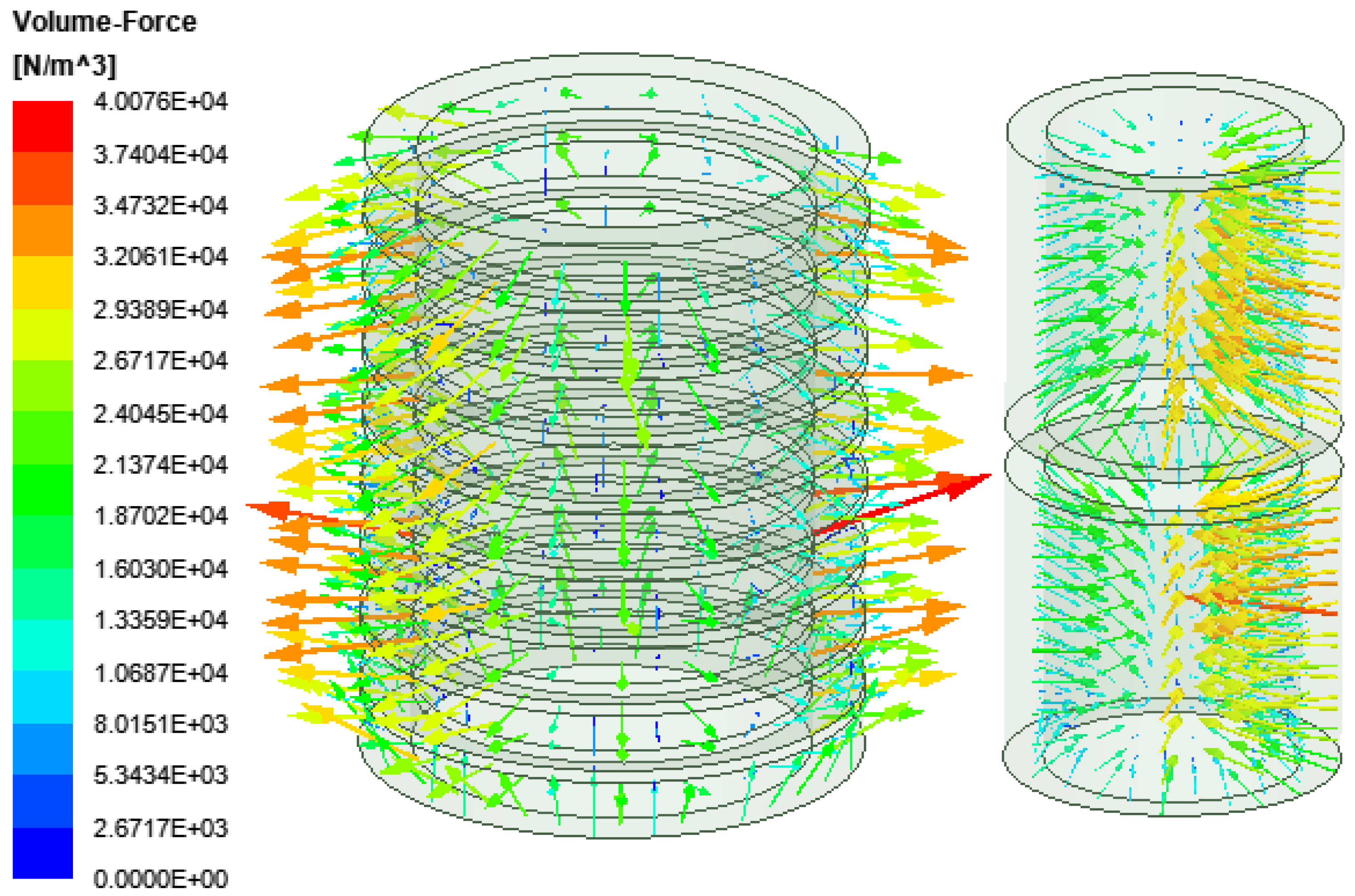
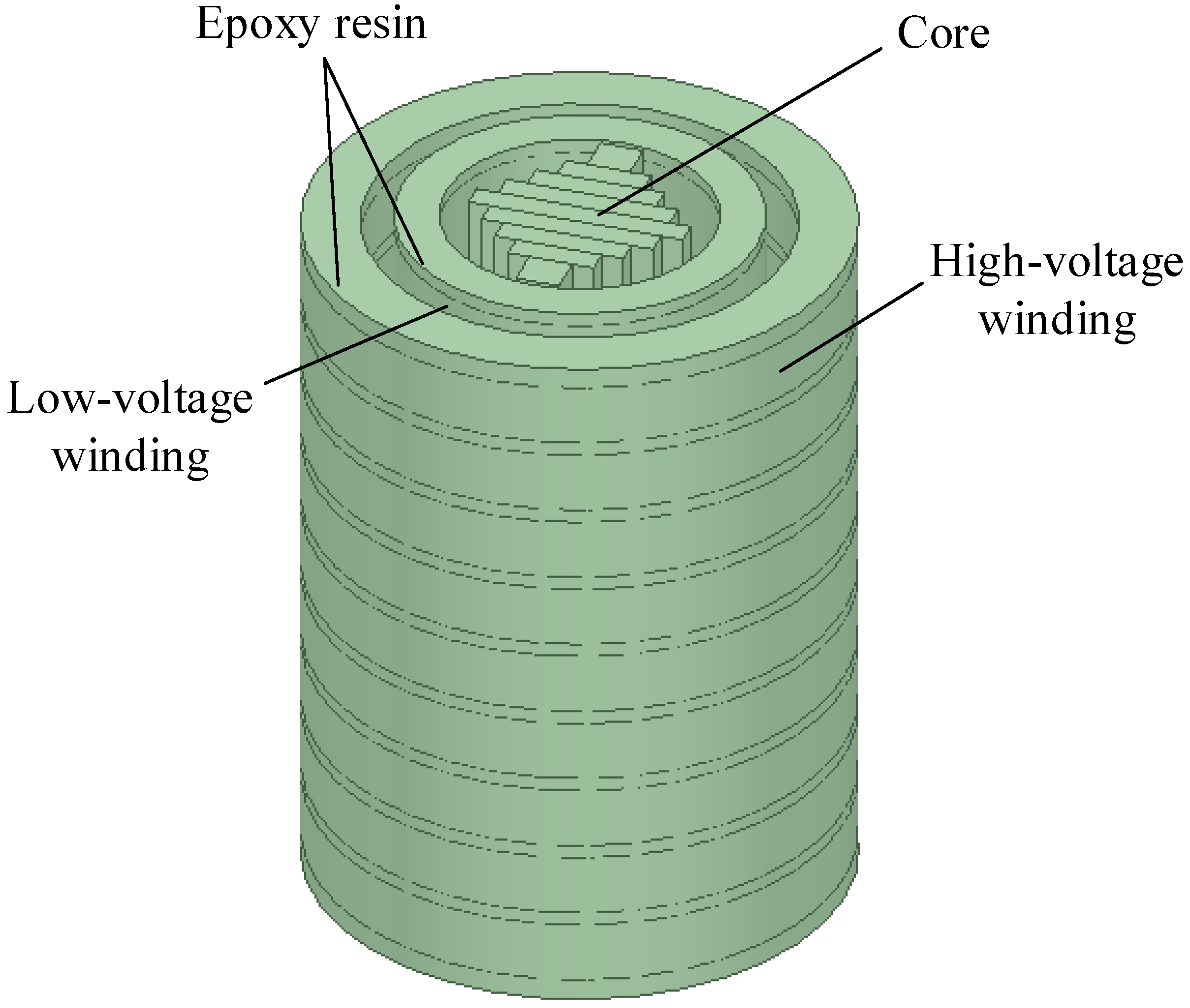
Under rated operating conditions, the electromagnetic forces in transformer windings are subjected to two forces: the radial electromagnetic force, and the axial electromagnetic force. The radial electromagnetic force is along the coil radius, the inner and the outer windings of the current direction are opposite, so that the inner coils bear the inward force, and the outer coils bear the outward force. The axial electromagnetic force is along the coil axis, and the coils also bear inward or outward force. When the transformer works under a short-circuit fault, if the short-circuit electromagnetic force is large enough, the winding will deform due to insufficient capability to resist short-circuit dynamic force. Therefore, when a transformer fault occurs, the magnitude and distribution of the electromagnetic forces in the winding will change. The electromagnetic force of a winding is an important indicator for monitoring the operating conditions of the transformer.
Accurate calculation of the electromagnetic forces provides a reliable assessment of the operating conditions of the transformer. According to the Lorentz law, the electromagnetic forces on the windings can be calculated by Equation (23).
where
is the electromagnetic force of a winding,
is the number of turns of coil in the winding,
is the magnetic leakage density,
is the current in the winding, and
is the length of wire in the winding.
5.1. Fractional Order Currents
To calculate the electromagnetic force, the winding current must be calculated. In the traditional circuit model, the current is expressed as:
where
is the integer order winding current,
is the supply voltage,
is the impedance of the winding, and
is the equivalent capacitance of the winding.
In the fractional order circuit model, the fractional-order capacitance is used instead of the integer-order capacitance, and the integer-order differentiation is changed to fractional-order differentiation by using the fractional-order differentiation operator. The expression is shown in Equation (25).
where
is the fractional order winding current, and
is the fractional order equivalent capacitance of the winding.
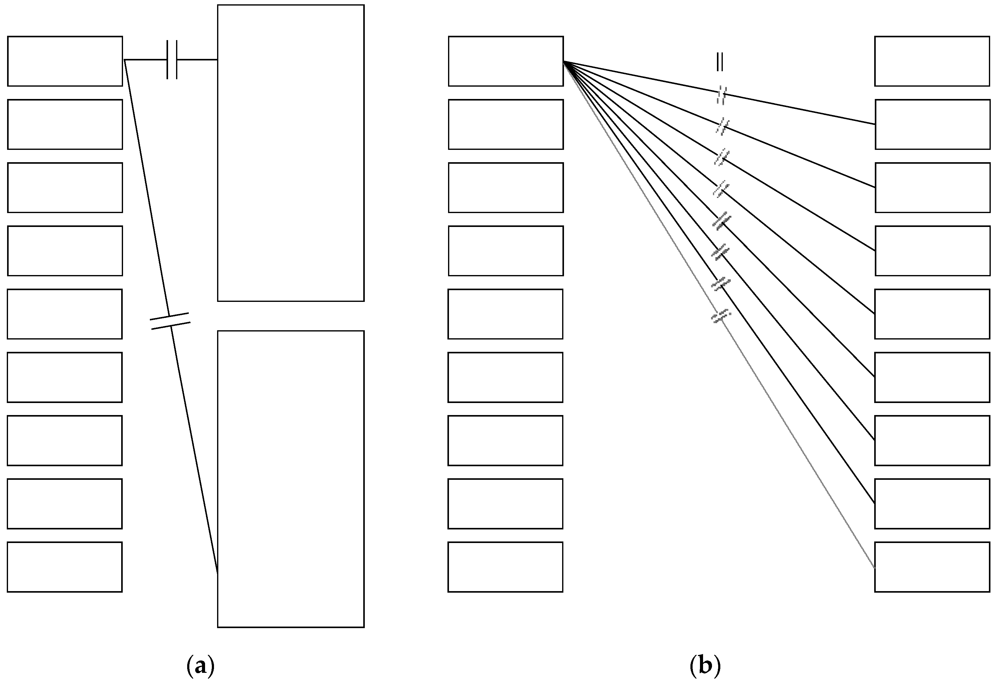
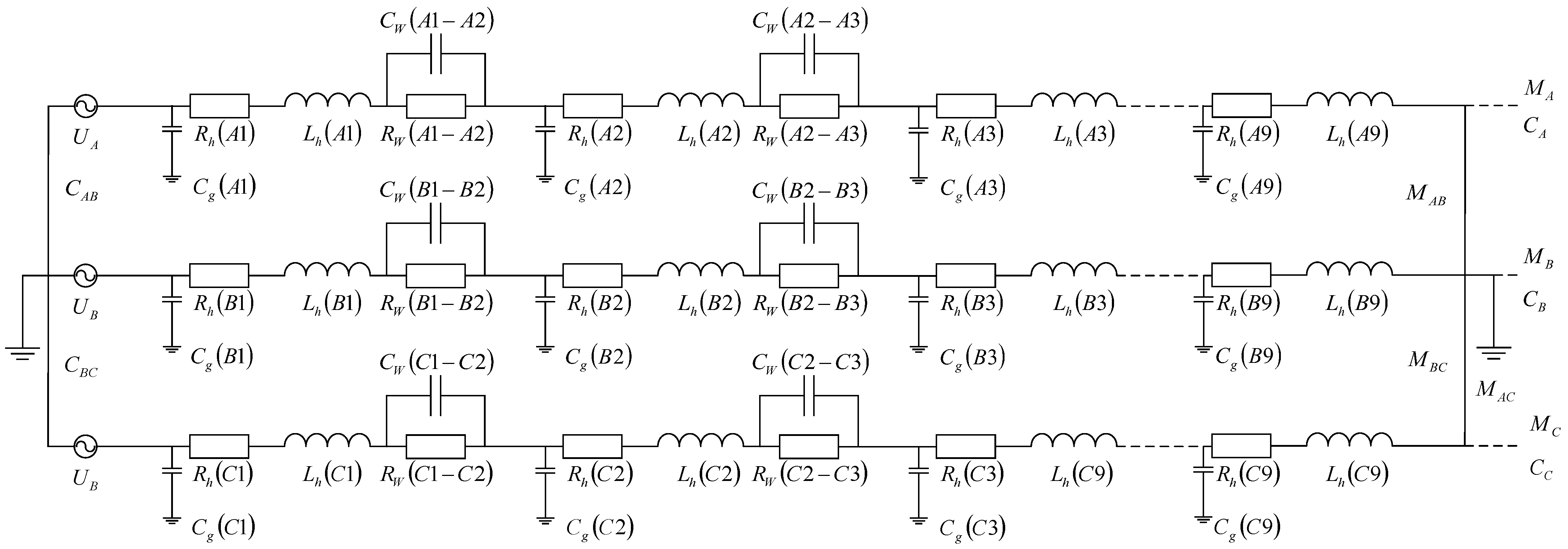
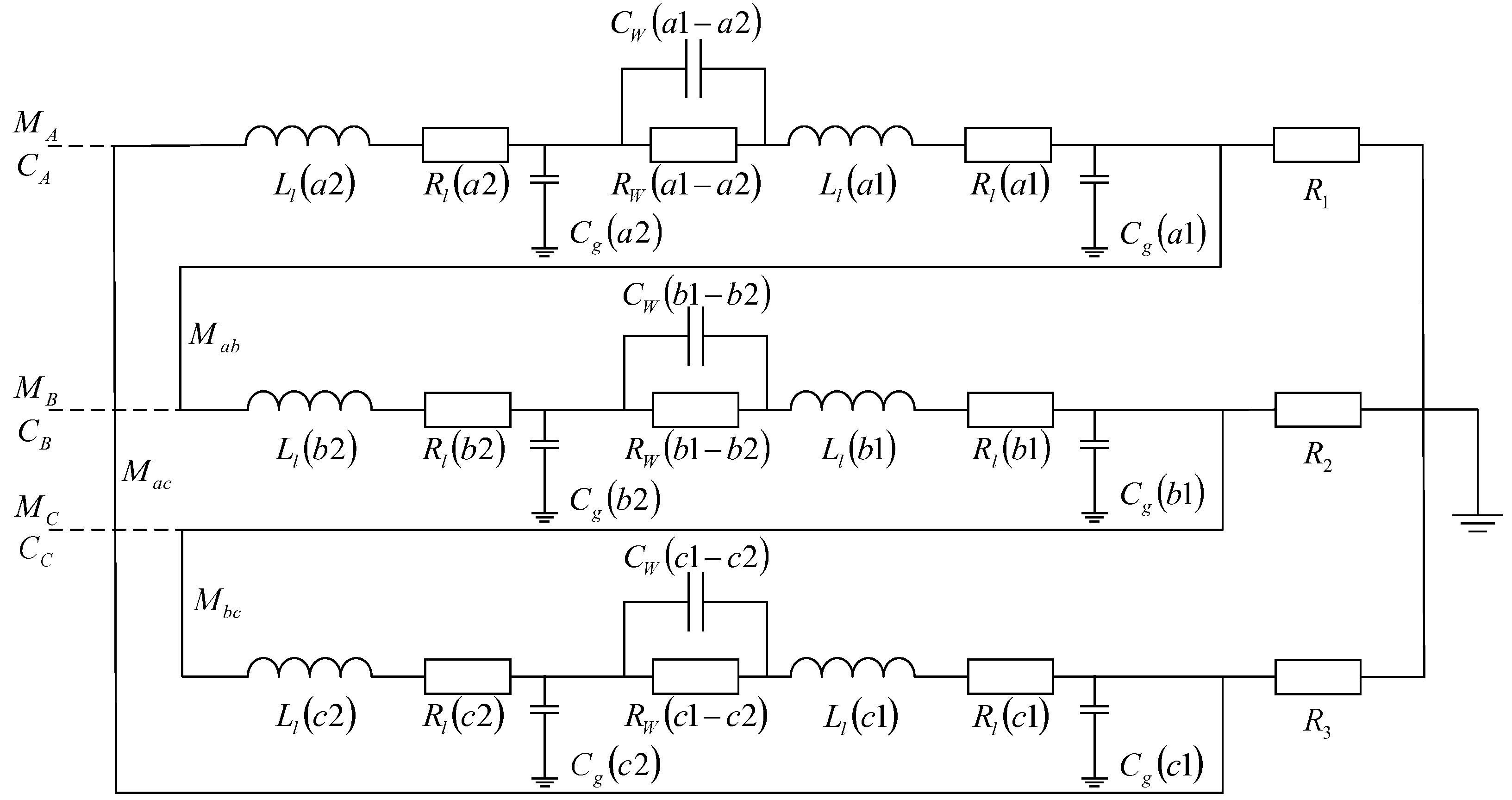
Take the A-phase winding as the example for calculation. Based on the lumped parameter equivalent circuit model, the fractional-order current expressions for the high-voltage winding and low-voltage winding of phase A are shown as follows.
where
is the high-voltage winding current,
is the low-voltage winding current,
is the impedance of the high-voltage winding of phase A,
is the impedance of the low-voltage winding of phase A,
is the potential of each segment of the high-voltage winding of phase A,
is the potential of each segment of the high-voltage winding of phase B,
is the potential of each segment of the low-voltage winding of phase A,
is the coupling capacitance between two adjacent series high-voltage windings of phase A,
is the coupling capacitance between two adjacent series low-voltage windings of phase A,
is the coupling capacitance between the high-voltage windings and the low-voltage windings of phase A,
is the coupling capacitance between the high-voltage windings of phase A and the high-voltage windings of phase B,
is the coupling capacitance between the windings and ground, and
is the fractional order.
At present, studies on fractional order capacitance mostly use the integer order to approximate fractional order, but there is still no clearer unified standard for obtaining the order. In this paper, 0.8 order is used as the reference value, the 0.02 order step is taken based on the reference value for simulation calculation, and the actual calculation results are more consistent with the transformer rated value when the fractional order is taken as 0.9. Therefore, the calculation in this paper is performed on the basis of 0.9 order.
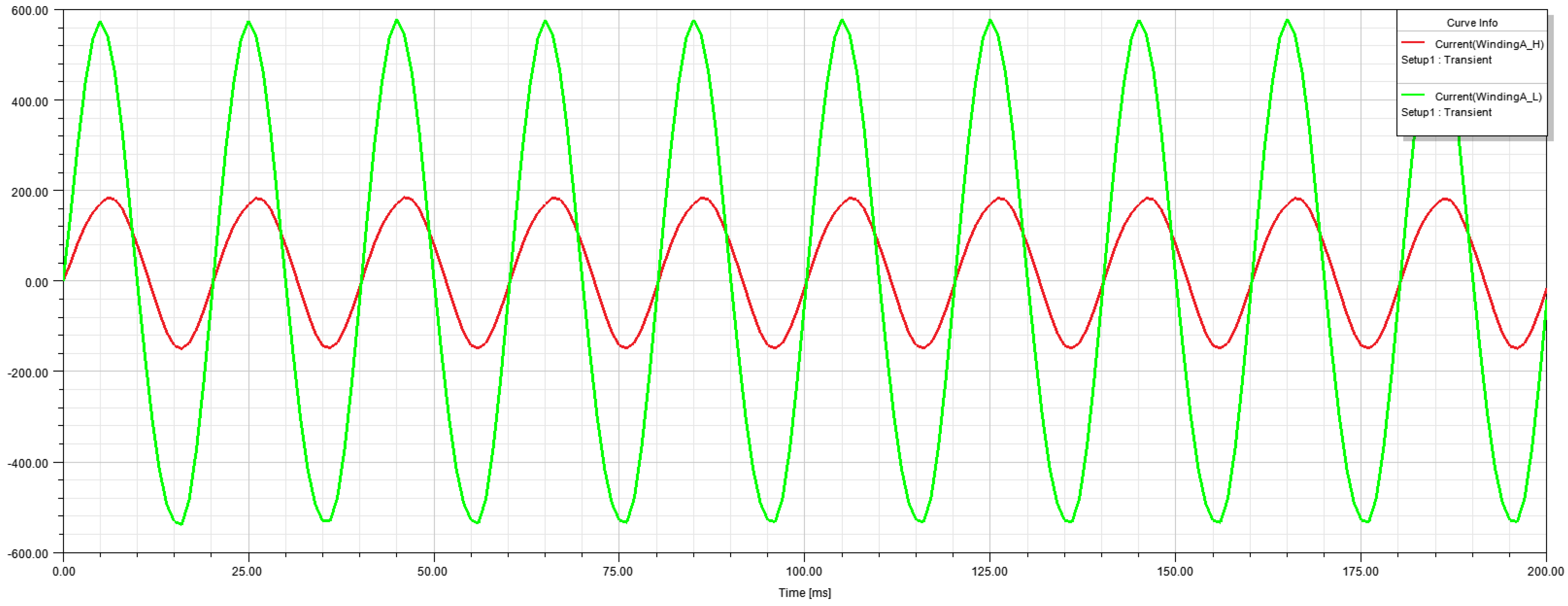
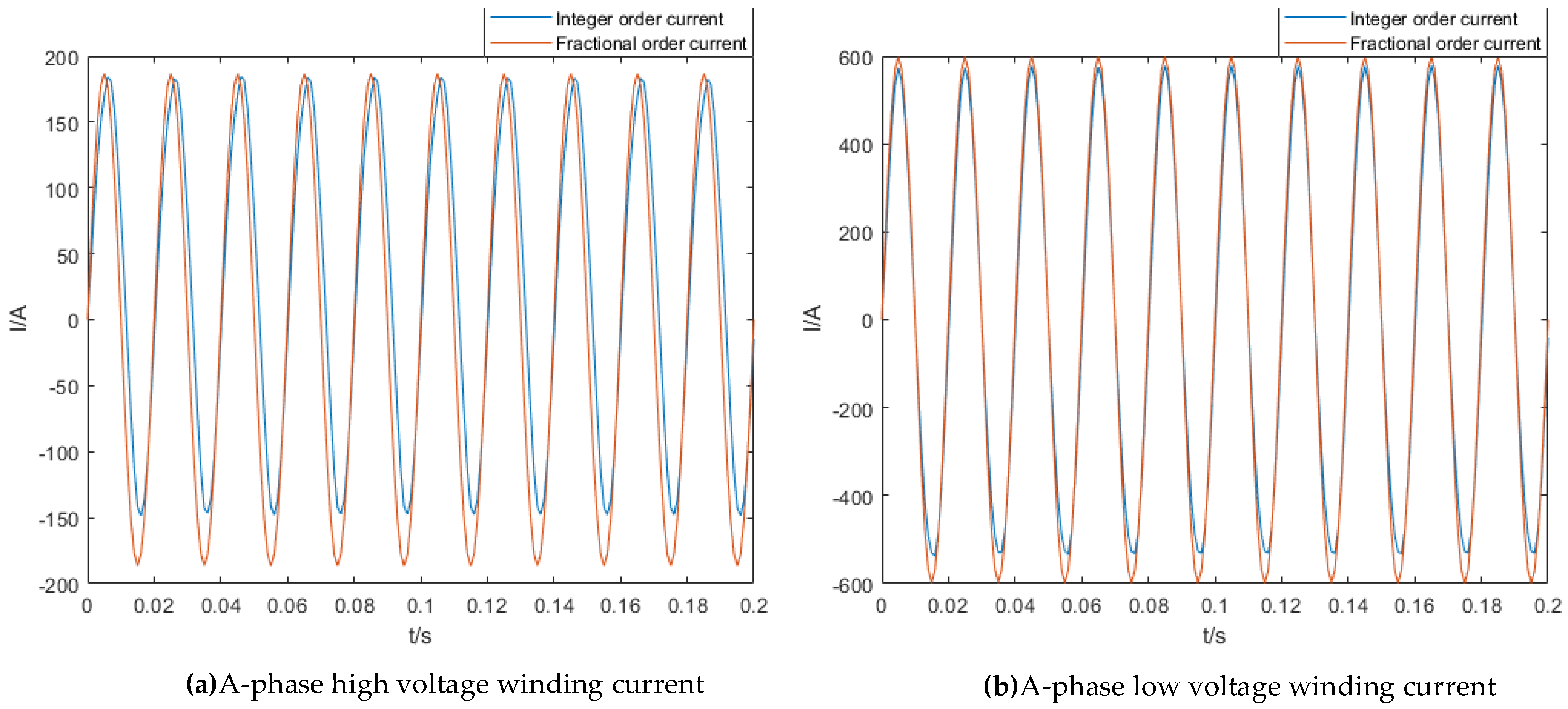
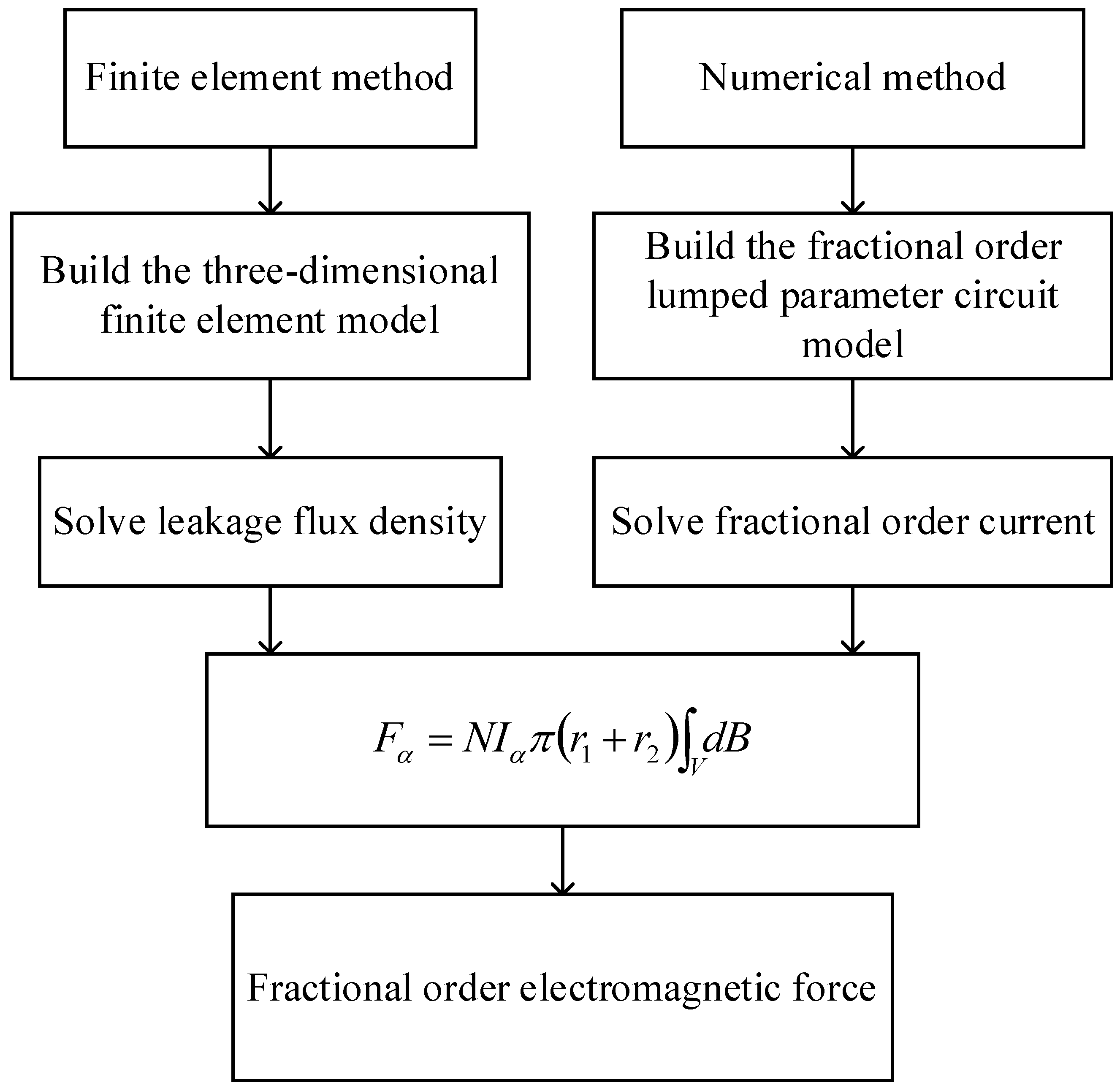
Use finite element method to calculate the integer order current of the transformer winding and numerical method to calculate the fractional order current of the transformer winding. Taking the A-phase winding as the example, the fractional order current waveforms of the A phase high-voltage and low-voltage windings under the rated operating conditions are obtained as shown in
Figure 15.
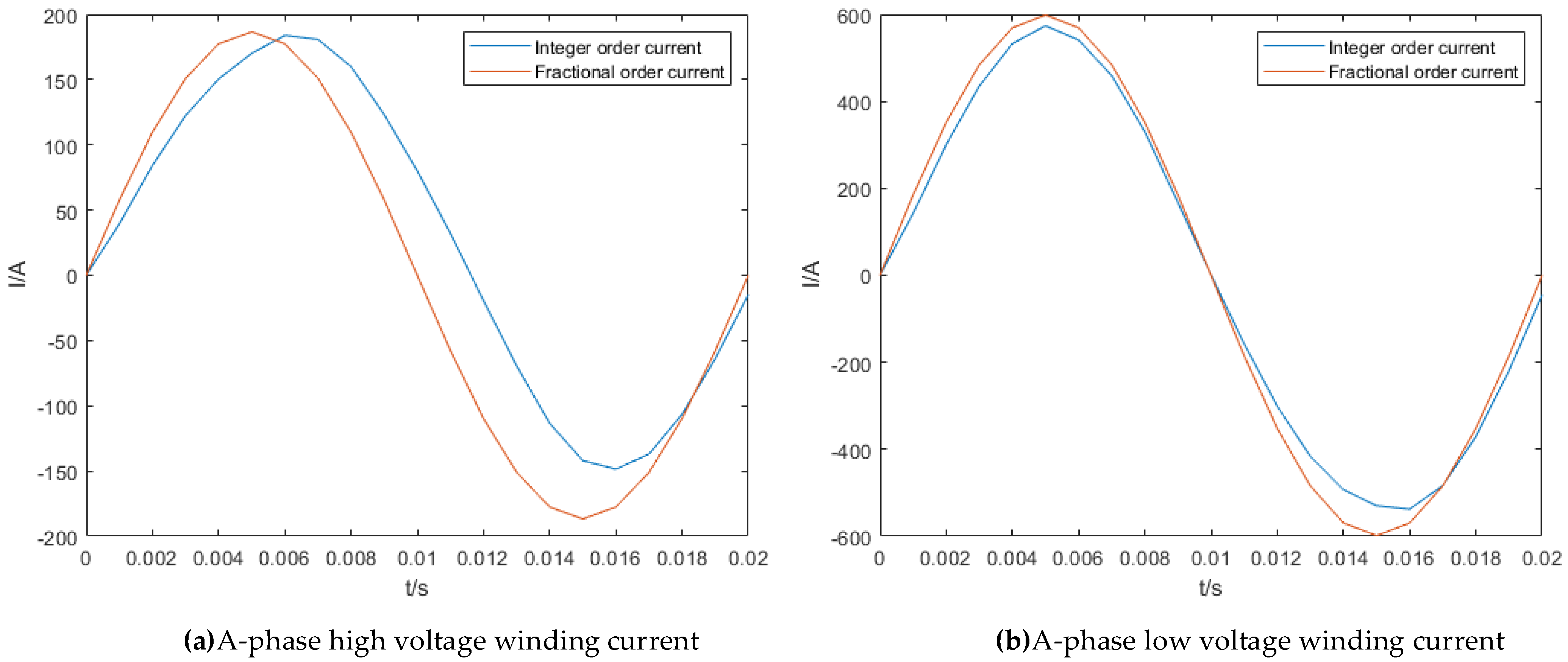
To analyze the results easily, the current waveforms were amplified within one period as shown in
Figure 16.
The rated amplitude value of the phase current of the high-voltage winding is 186.6762 A, and the rated amplitude value of the phase current of the low-voltage winding is 598.492 A. The simulation results show that in the positive half period, the values of fractional current and integer current are close, and the values of fractional current are higher and closer to the rated values. In the negative half period, the amplitude values of integer order phase current of the high-voltage winding and low-voltage winding are both significantly smaller than the rated values, and the waveforms of the integer order current are not the strictly sinusoidal waves. The results for the integer order current are not correct in the negative half period mainly because of the systematic error of the finite element method. The fractional order current is the standard sinusoidal wave, and the values are closer to the rated values. The simulation results for the fractional order model are more accurate than those for the integer order model.
To further verify the accuracy of the fractional order model, the amplitude value of the secondary phase current was calculated for five different operating conditions: 50% load rate, 80% load rate, 100% load rate, 150% load rate and 200% load rate. The results are shown in
Table 5.
As the load ratios increase, the calculation errors of the integer order simulation model become larger and larger. The calculation results are more accurate using the 0.9 order fractional order model.
Compare the above calculation results with existing research results to verify the accuracy of the fractional order model. The errors of the current on the secondary side at different load rates studied by paper [
25] are shown in
Table 6.
By comparing the error values, the fractional order model proposed in this paper is shown to be more accurate than the finite element model.
5.2. Fractional Order Electromagnetic Forces
Equation (23) is modified to give the expression for the fractional order electromagnetic force:
where
is the fractional order electromagnetic force,
is the fractional order current,
is the number of turns of the coil,
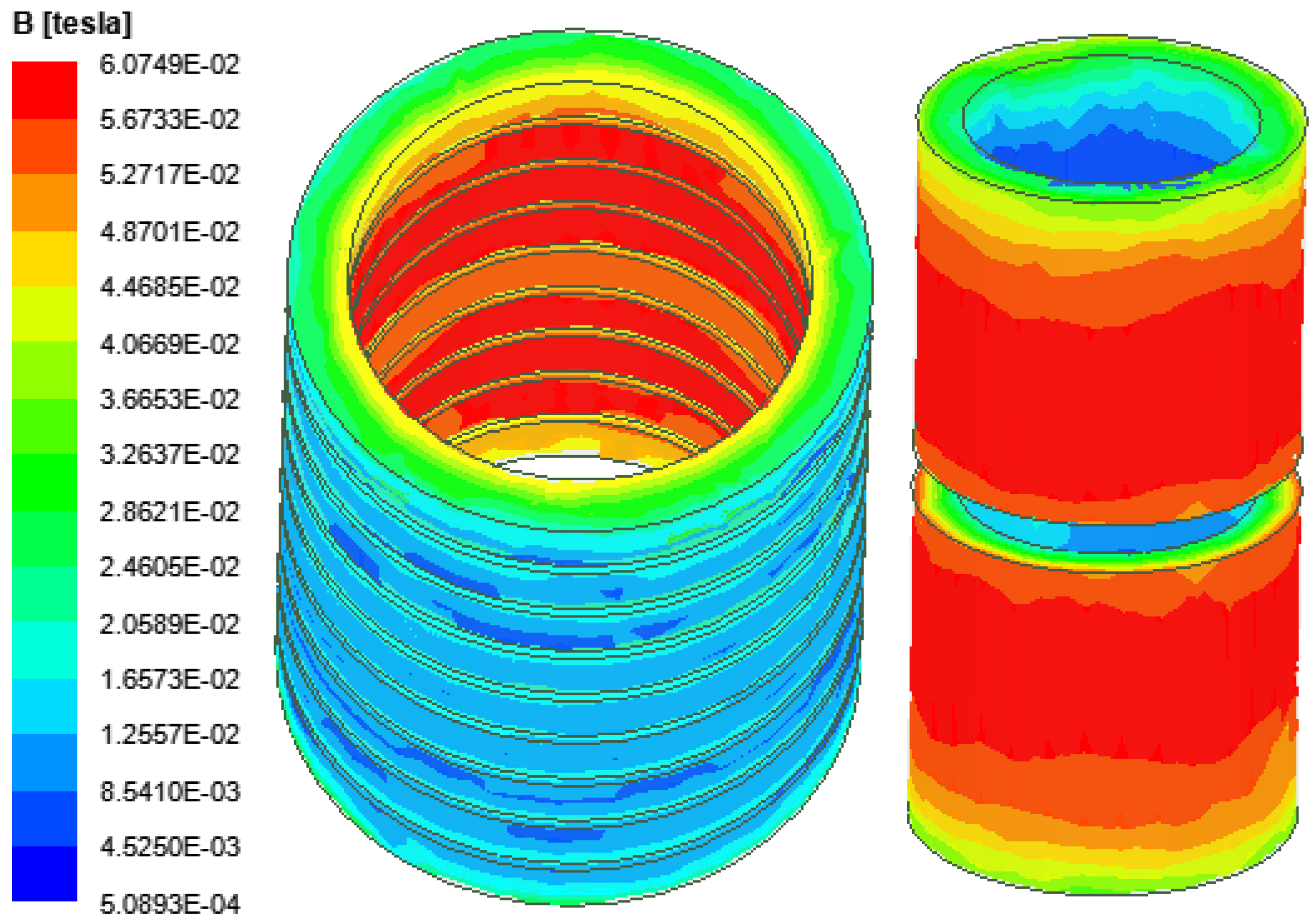
is the magnitude of the magnetic flux density, and
are the inner radius and outer radius of the winding, respectively.
After obtaining the magnitude of the magnetic flux density by Equation (4) and the fractional order current by Equation (25), the field-circuit coupling method is applied to solve for the fractional-order electromagnetic forces in the windings, as shown in
Figure 17.
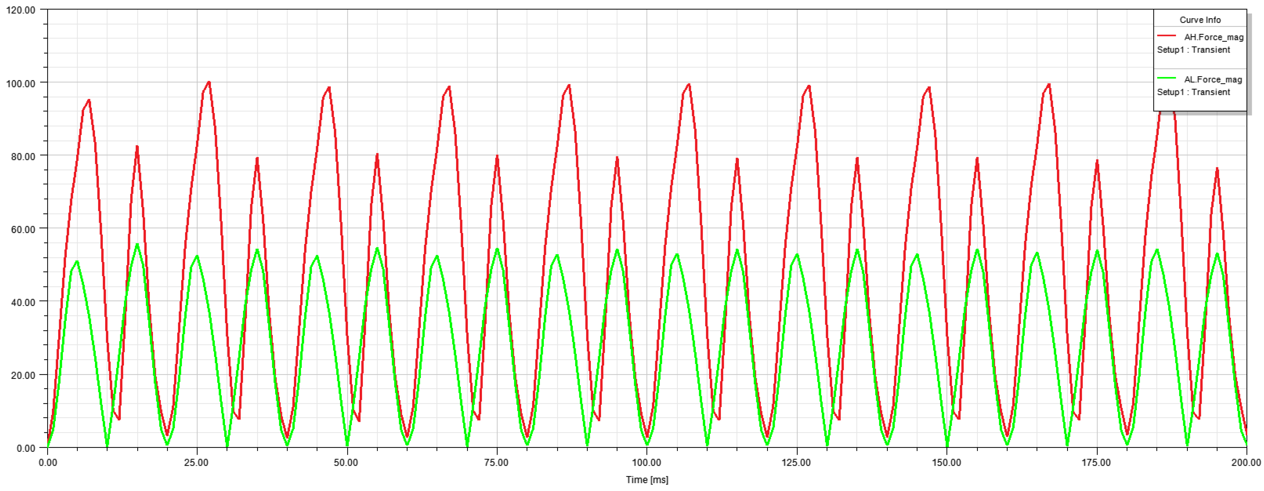
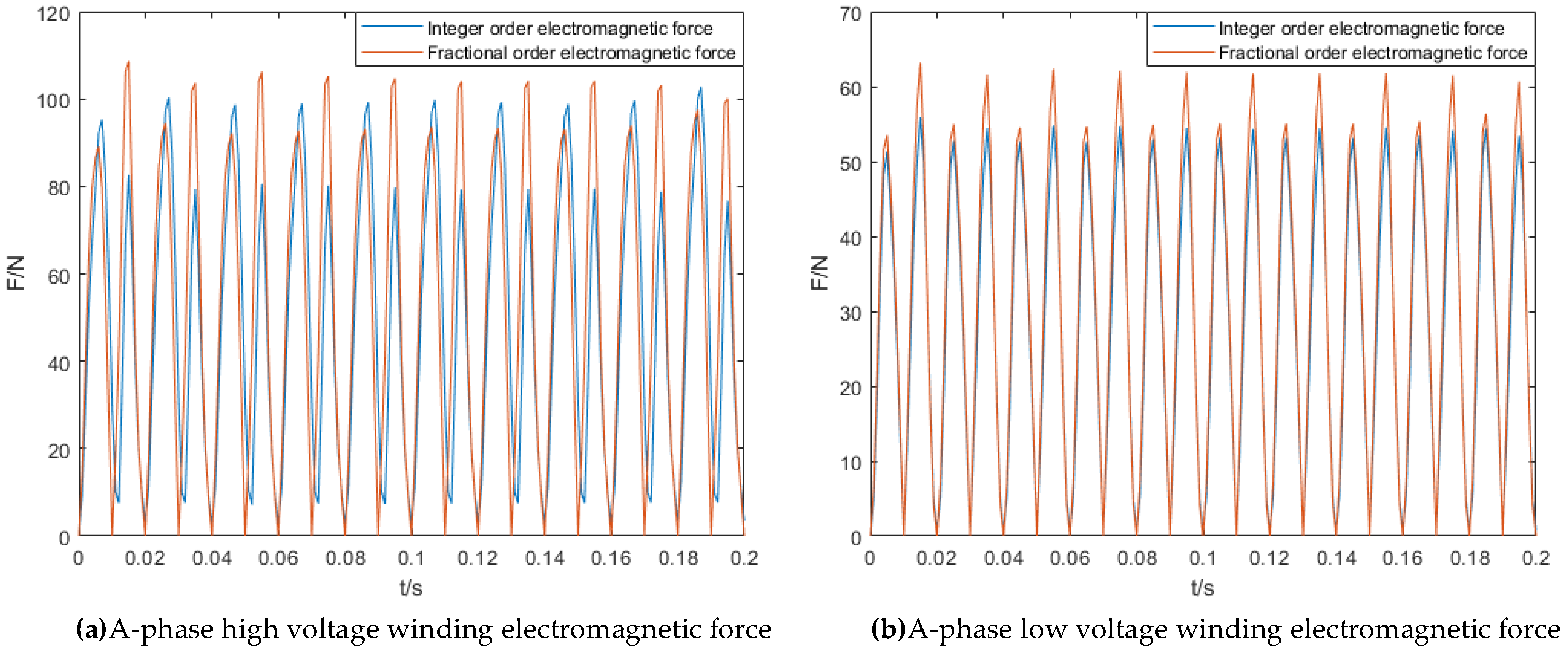
The integer order and fractional order electromagnetic forces in the A-phase winding under rated operating conditions are shown in
Figure 18.
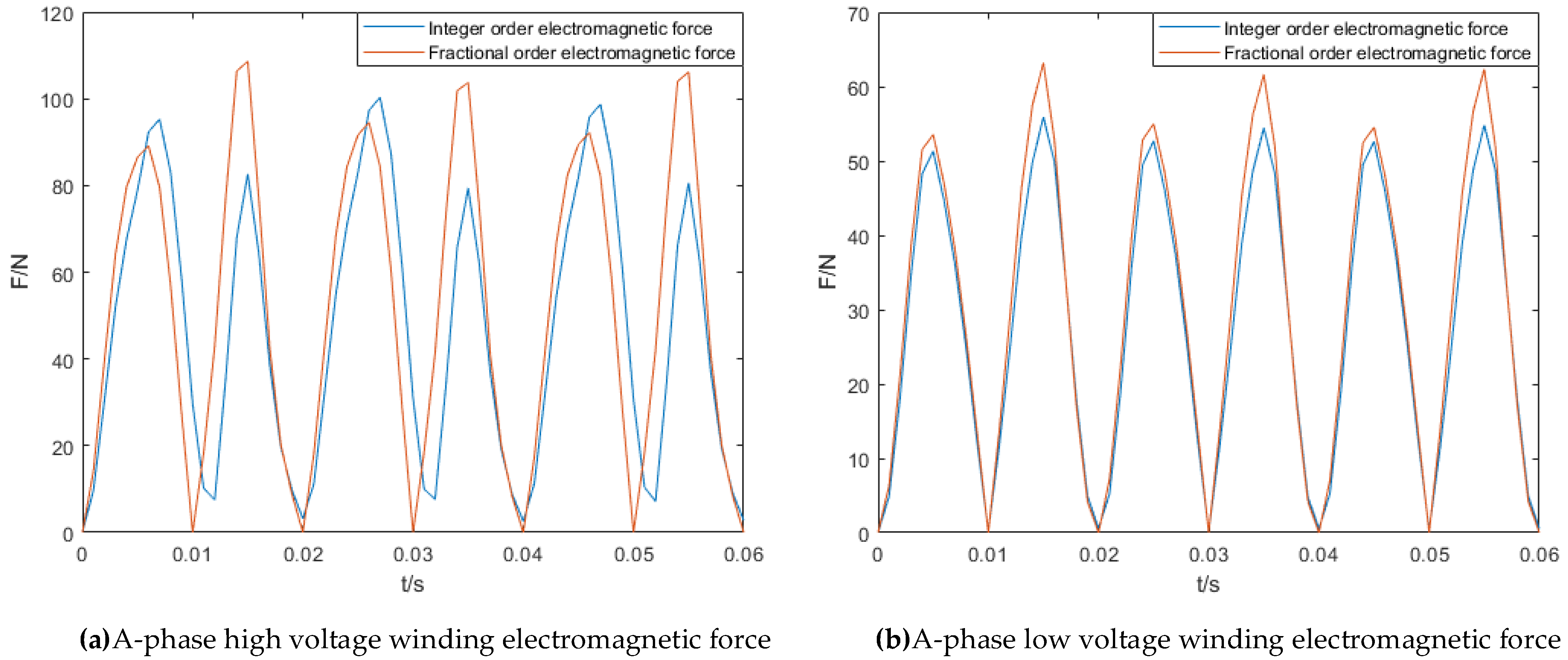
The waveform is amplified for convenient observation and analysis as shown in
Figure 19.
It can be seen that the maximum electromagnetic force of the high-voltage winding under normal conditions is around 105 newtons, and the maximum electromagnetic force of the low-voltage winding under normal conditions is around 62 newtons. The fractional order model is simpler, the calculation results are more accurate, and the running time of the program is shorter.
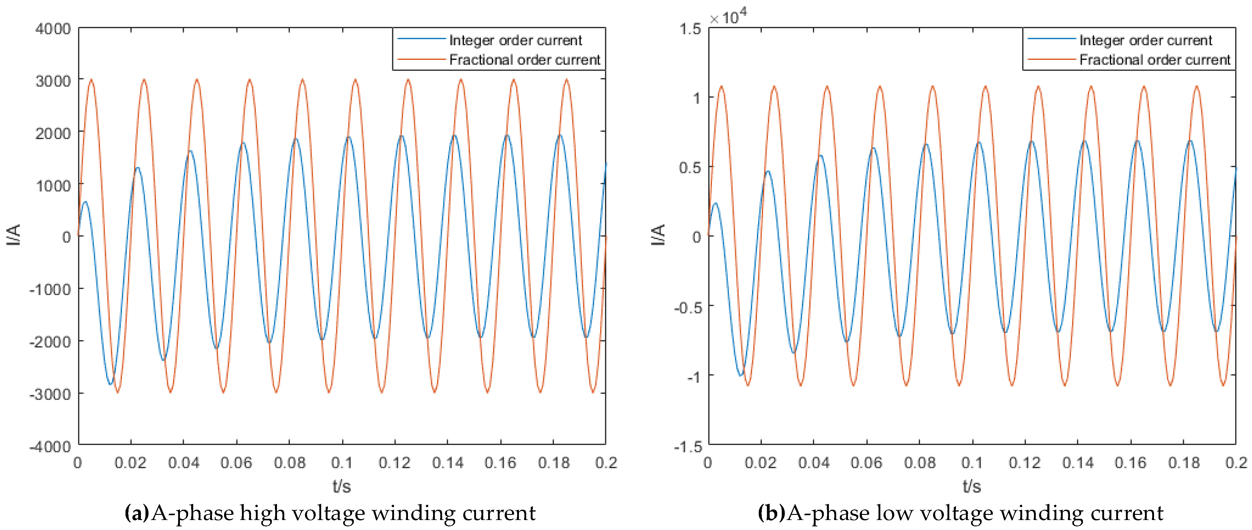
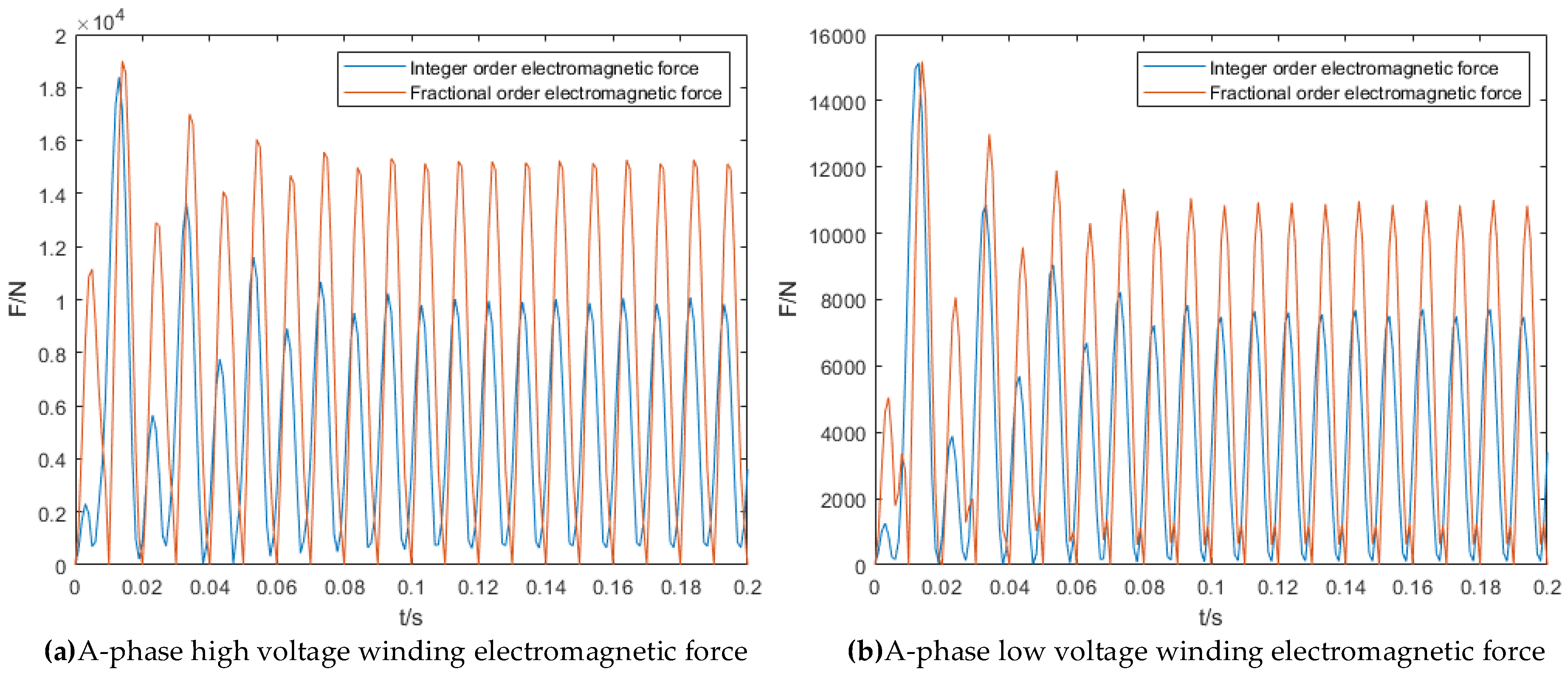
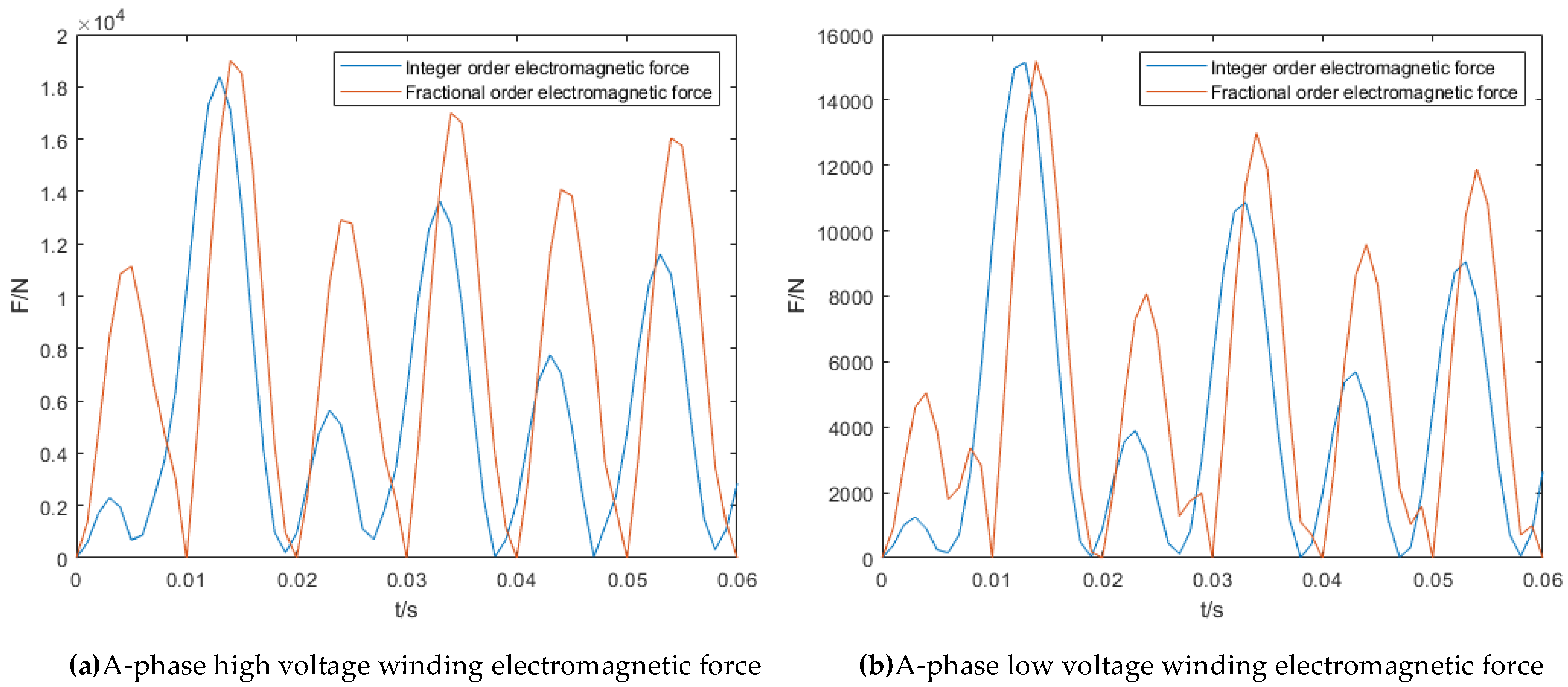
Three-phase short-circuit faults are the most serious faults in transformers. Inadequate short-circuit resistance of the winding is prone to cause winding deformation and, in severe cases, line tripping or even explosion and burning. Simulations have been carried out to calculate the fractional and integer order current and electromagnetic forces in three-phase short-circuited working conditions. The currents and electromagnetic forces are shown in
Figure 20 and
Figure 21.
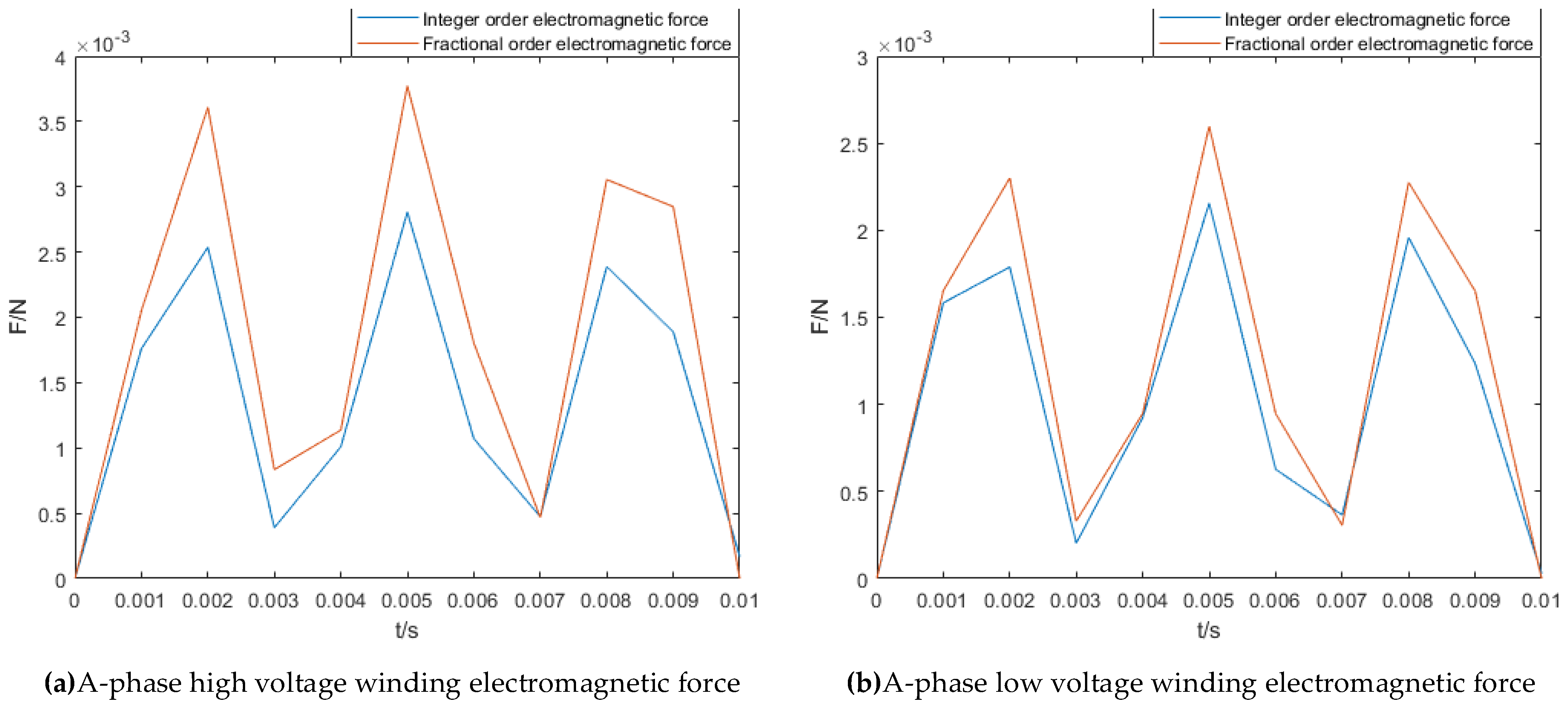
The waveform is amplified for convenient observation and analysis as shown in
Figure 22.
The figures show that the maximum short-circuit impulse current of the A-phase high-voltage winding under three-phase short-circuit conditions is 10 kA, the maximum short-circuit impulse current of the low-voltage winding is 3 kA, and the electromagnetic force applied to the winding reaches more than 14,000 N, which seriously endangers the operational safety of the transformer, which should be removed from operation in time before power failure.
Compare the above values with existing research results to verify the accuracy of the fractional order model. Authors of [
26] used the same transformer model as described in this paper and determined that under three-phase short-circuit conditions, the electromagnetic force of the high-voltage winding is about 14,000 N, and the electromagnetic force of the low-voltage winding is about 10,000 N. Similarly to the results obtained with the finite element method, the calculation results obtained by [
26] were smaller than those obtained with the fractional order model. If the transformer is designed based on inaccurate calculation results, it may be damaged because of insufficient mechanical strength when working under exceptional conditions. By accurately calculating the winding force, the operating state of the winding ground can be reliably determined to avoid causing instability of the power system.
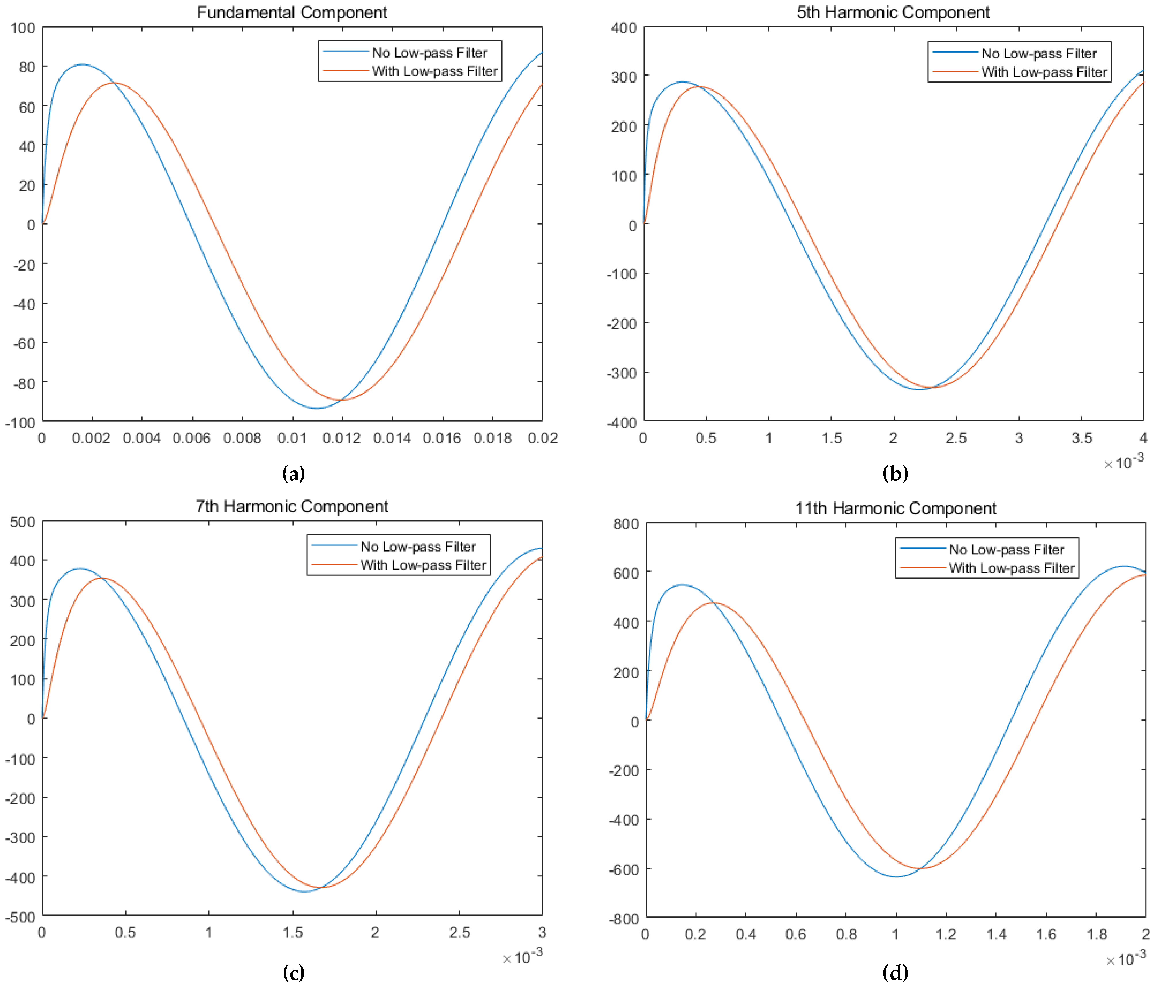
The transformer proposed in this paper is used in an offshore wind power platform. The offshore wind power system contains a large number of powered electronic devices, which may lead to an increase in the harmonic components in the power system. The effect of harmonic voltage and harmonic current on the transformer should be considered to obtain the accurate electromagnetic force in the windings. The forces on the fractional and integer orders of the A-phase winding in the 5th, 7th and 11th harmonic cases were simulated and analyzed. The electromagnetic forces are shown in
Figure 23.
Accompanying the presence of harmonics, the winding current will be disturbed within a certain scope. Although the transient value of the electromagnetic force does not exceed a limited value, prolonged operation in a harmonic environment may lead to overload and overheating, which would seriously damage the equipment. Therefore, it is essential to eliminate harmonics in time.


