Article

Mechanical Behavior of Large Symmetric Fiber Reinforced Polymer-Reactive Powder Concrete Composite Tanks with Floating Tops

1
Heilongjiang Key Laboratory of Disaster Prevention, Mitigation and Protection Engineering, Northeast Petroleum University, Daqing 163319, China
2
China-Pakistan Belt and Road Joint Laboratory on Smart Disaster Prevention of Major Infrastructures, Southeast University, Nanjing 211189, China
*
Author to whom correspondence should be addressed.
Symmetry 2024, 16(1), 51; https://doi.org/10.3390/sym16010051
Submission received: 19 October 2023 / Revised: 1 November 2023 / Accepted: 14 December 2023 / Published: 29 December 2023

Abstract

:
In order to investigate the mechanical behavior of FRP-reactive powder concrete composite tanks with floating tops (FRPCTs) subjected to gravity, twenty-two full-scale FRPCTs were designed with varying parameters for the inner diameter of the storage tank (D) and the thickness of the reactive powder concrete (tc). Based on nonlinear constitutive models and the contact of the materials, and considering tank–liquid coupling, three-dimensional finite element refined models of FRPCTs were established under gravity with ADINA8.5 finite element software, and finite element models of FRPCTs under gravity were verified based on theoretical frequency formulae and existing static tests. Then, the influence of the regularity of different parameters on the equivalent stress, hoop stress, radial stress, and axial stress of the FRPCTs was obtained, and the stress distributions of FRPCTs were clearly described. The results show that the natural frequency of FRPCTs increases gradually with an increase in the height of the tank liquid (Hw); however, the natural frequency of FRPCTs reduces with an increase in D. The equivalent stress, hoop stress, radial stress, and axial stress of the FRP plate and RPC decrease slowly with an increase in tc. The axial stress of the inner RPC increases with an increase in D. The equivalent stress of the inner FRP plate subjected to gravity is distributed in a W shape, the hoop stress, and the axial stress of the FRPCTs are distributed in a U shape, and the radial stress of the inner FRP plate is distributed in an I shape. The maximum displacement occurs in the middle of the FRPCTs, and the bonding between the FRP plate and the concrete is better. Finally, a calculation formula for the variation in the regularity of the tc is developed with different D, and design and construction suggestions for FRPCTs are given, which can provide technical support for the application of the FRPCTs in practical engineering.

1. Introduction

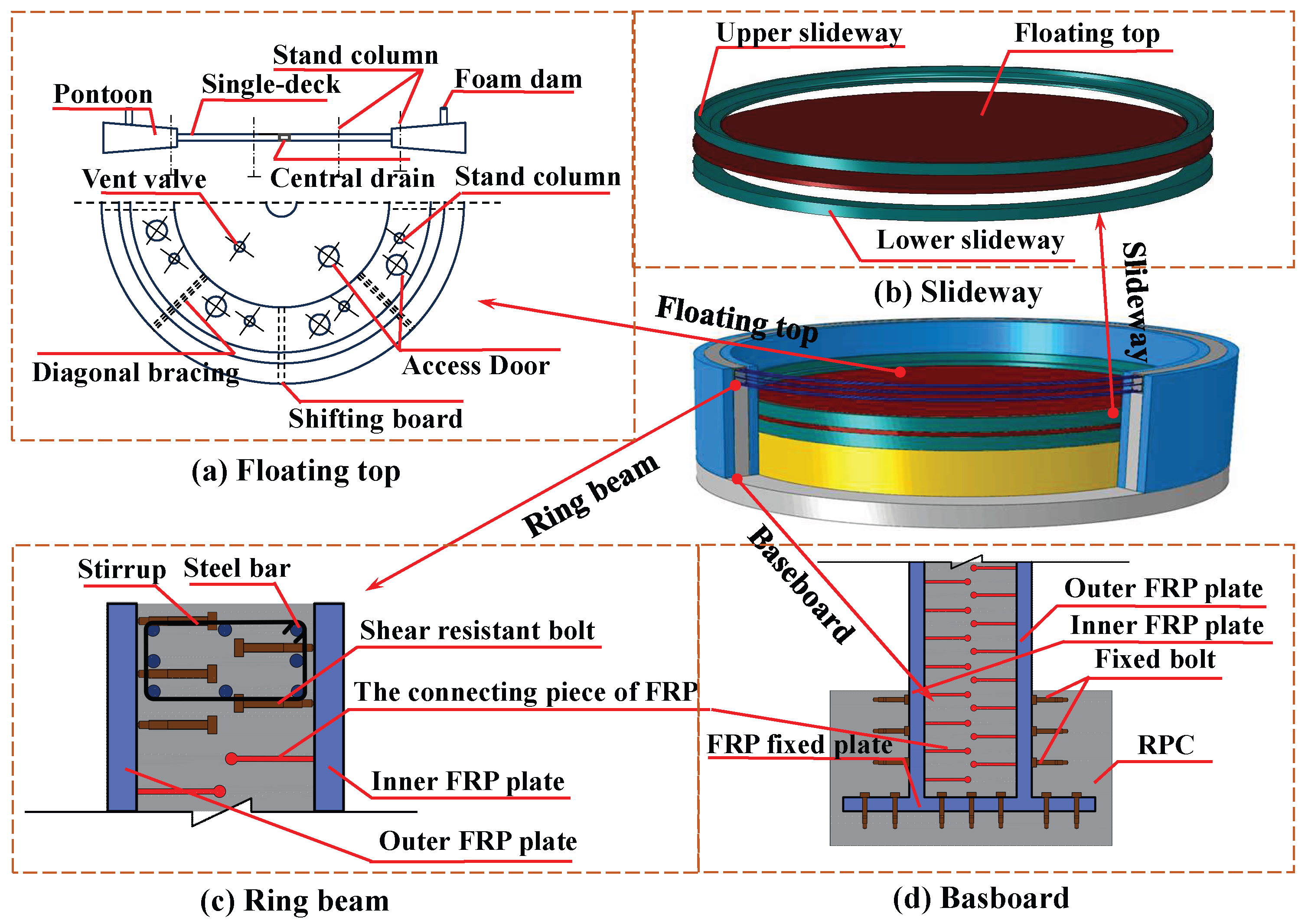
At present, large vertical steel storage tanks are widely used in the petrochemical field because of their large volumes and convenient construction [1]. However, with the development of storage tanks towards super-large volumes and corrosion resistance, a large vertical steel storage tank cannot meet the needs of practical engineering. Because of local instability [2,3,4] and corrosion [5] under the action of strong earthquakes and wind or humid environments, it is urgent to propose a novel type of vertical storage tank structure. As we all know, reactive powder concrete (RPC) has good mechanical properties and durability [6,7] with added fiber, so the brittle behavior of conventional cementitious composites can be improved significantly [8,9]. The combination of RPC and FRP can give full play to the excellent mechanical behaviors of the materials [10,11]. Based on this, a novel type of composite storage tank with a concentric double-layer FRP plate and RPC is proposed, as shown in Figure 1, and the tank wall can be formed by pouring RPC into the interlayer of the concentric double-layer FRP plate; then, the floating top is established. Finally, the top ring beam is built to form the novel composite storage tank. The concentric double-layer FRP plate subjected to loading has a restraint effect on the RPC, so the RPC is in a state of biaxial stress, and the compressive strength of the RPC can be improved. The RPC can also prevent local buckling of the FRP plate. This new type of composite storage tank can give full play to the excellent strain-hardening behavior and plastic deformation ability of the RPC [12]. The combination of the RPC and a concentric double-layer FRP plate can significantly improve the stability and corrosion resistance of the FRPCTs. During construction, a concentric double-layer FRP plate can be used as a template for pouring the RPC. This novel kind of composite storage tank will be widely applied to the freeze–thaw low-temperature corrosion environment.
So far, many studies on the mechanical behavior and structural design of storage tanks have been widely conducted by scholars at home and abroad. Numerical analysis of the elastic deformation of round tank walls was carried out by Beaufait F W [13], and the mid-point difference method was proposed to confirm the elastic deformation of round tank walls under axisymmetric effects, which could provide organization methods for the application of computers. A numerical analysis of the stress distribution of cylindrical steel tanks was carried out by Balendra T et al. [14], and the maximum shear force, the maximum overturning moment, and the maximum stress of the tank wall for full-scale steel tanks could be obtained, and design charts for cylindrical steel tanks were developed in this study, which could provide a reference for the design of the tanks. The influence of design methods on the tank walls of large storage tanks in API standard 650-2013 [15] was studied by Azzuni E et al. [16], and the theory of a basic thin-wall elastic matrix method for the wall thickness design of large steel tanks was proposed, which could give more accurate shell designs compared with the one-foot method (1FM) and the variable design point method (VDM). The influences of the design method on storage tanks on rigid foundations were studied by Wieland M [17], and a simplified design method for storage tanks considering liquid convection and pulsation on the tank wall was proposed, which was adopted by European standard 8-1998. However, the simplified design is still at the stage of linear analysis for storage tanks. A numerical analysis of the limit state of buckling failure for storage tanks under flood–hurricane coupling was carried out by Huang M [18], and a formula to calculate the limit state of storage tank buckling failure under flood–hurricane coupling was established. The influences of boundary conditions on the modes of square storage tanks were determined by Jhung M J [19], the natural frequencies and mode shapes of square storage tanks under different boundary conditions were obtained, and the results show that an increase in the fluid in the tank reduces the frequency. The influences of grid division on local defect stress in large storage tanks were analyzed by Wang L L [20]; simplified two-dimensional and three-dimensional models of large storage tanks were established; and the results showed that the simplified two-dimensional models of large storage tanks that were established had enough accuracy to simulate the static analysis of full-scale large storage tanks. A shaking table experiment on a steel storage tank was conducted by De Angelis M [21], and a simplified numerical model of the storage tank was established and proved. Experiments on the sloshing wave heights of steel storage tanks were conducted by Sun et al. [22,23]; the calculated results for sloshing wave heights in steel storage tanks with the different standards were compared, and the results showed that the results of API 650–2013 were conservative.
Although the research on traditional steel storage tanks is relatively mature, the research on the mechanical behavior of composite storage tanks has hardly been reported yet. The interaction between the FRP plate and the RPC has not been clarified. Meanwhile, there is a lack of in-depth understanding of the natural characteristics and force mechanisms of the FRPCTs. Therefore, it is of great theoretical significance and practical value in actual engineering to research the force mechanism of FRPCTs under gravity and the mode analysis of FRPCTs. In this paper, a total of twenty-two full-scale FRPCT specimens are designed. The numerical simulation studies on the stress distribution of FRPCTs are conducted based on theoretical verification. The influences of tc and D on the mechanical behavior of FRPCTs can be investigated. Then, the equivalent stress, hoop stress, radial stress, and axial stress of the FRP plate and RPC of FRPCTs are obtained. Finally, based on the simplified calculation model and the force mechanism of FRPCTs, the calculation formula for the variation regularity of tc is regressed with the different D by polynomial fitting methods, and the design suggestion of FRPCT is put forward, which can lay the foundation for the application of such composite storage tank in practical engineering.

2. Specimen Design

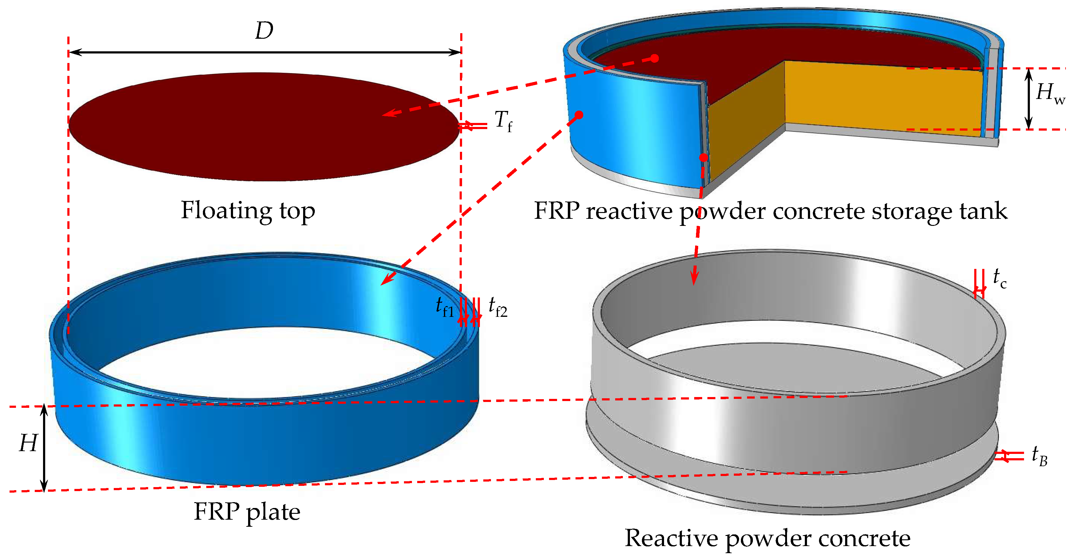
To investigate the mechanical behavior under gravity of FRPCTs with floating tops, a total of twenty-two full-scale FRPCTs are designed, taking the thickness of RPC (tc) and the inner diameter of the storage tank (D) as the main parameters. The specific parameters can be seen in Figure 2 and Table 1. The tf1 and tf2 represent the thickness of the FRP plate, the tB is the thickness of the baseplate of the storage tank, the Tf is the thickness of the floating top, and the Hw is the height of the tank liquid.

3. Finite Element Models (FEMs)

3.1. Simplified Mechanical Model of the FRPCTs

In this section, the simplified mechanical model of FRPCTs with floating tops is shown in Figure 3. According to the research on storage tanks carried out by the civil engineering department of Beijing University of Aeronautics and Astronautics [24,25], the principle of identical wall thickness and equal floor thickness of FRPCTs is adopted. The structure of the fully symmetrical cylindrical vertical of FRPCT is designed. It is assumed that the liquid in the storage tank is water, an ideal incompressible and non-rotational fluid.

3.2. Constitutive Models of Materials

3.2.1. Constitutive Models of FRP

The mechanical behavior of FRP is tested by test, which is a fiber-reinforced composite material with anisotropic properties, and the FRP is a thin-walled structure in practical engineering. Therefore, the FRP belongs to the category of plane stress (σ33 = τ23 = τ31). The material property constant of FRP is given in Equation (1).
σ 11 σ 22 τ 12 = E 1 1 v 12 v 21 v 12 E 2 1 v 12 v 21 0 v 21 E 2 1 v 12 v 21 E 2 1 v 12 v 21 0 0 0 G 12 ε 11 ε 22 γ 12 ( v 12 E 1 = v 21 E 2 )
where E1 represents elastic modulus along the fiber direction of the FRP, E2 represents elastic modulus in the vertical fiber direction of the FRP, v12 represents the Poisson ratio of the FRP, and G12 represents the shear modulus of the FRP.
When defining the ultimate strength of FRP in the ADINA, the ultimate tensile strength along the fiber direction (Xt), the ultimate tensile strength along the fiber direction (Yt), the ultimate compressive strength along the fiber direction (Xc), and the ultimate compressive strength along the vertical fiber direction (Yc) need to be defined. The specific formulae are derived in Equations (2)–(5).
X t = V f σ ftu
Y t = σ ftu [ 1 ( V f V f ) ( 1 E m E f ) ]
X c = V f σ fcu
Y c = σ mcu [ 1 ( V f V f ) ( 1 E m E f ) ]
where σftu represents the ultimate tensile strength of the fiber, σfcu represents the ultimate compressive strength of the fiber, σmtu represents the ultimate tensile strength of the resin, and σmcu represents the ultimate compressive strength of the resin.

3.2.2. Constitutive Models of the RPC

In this paper, the concrete damaged plasticity (CDP) model is adopted to simulate the RPC. The definition of the CDP is shown in Table 2.
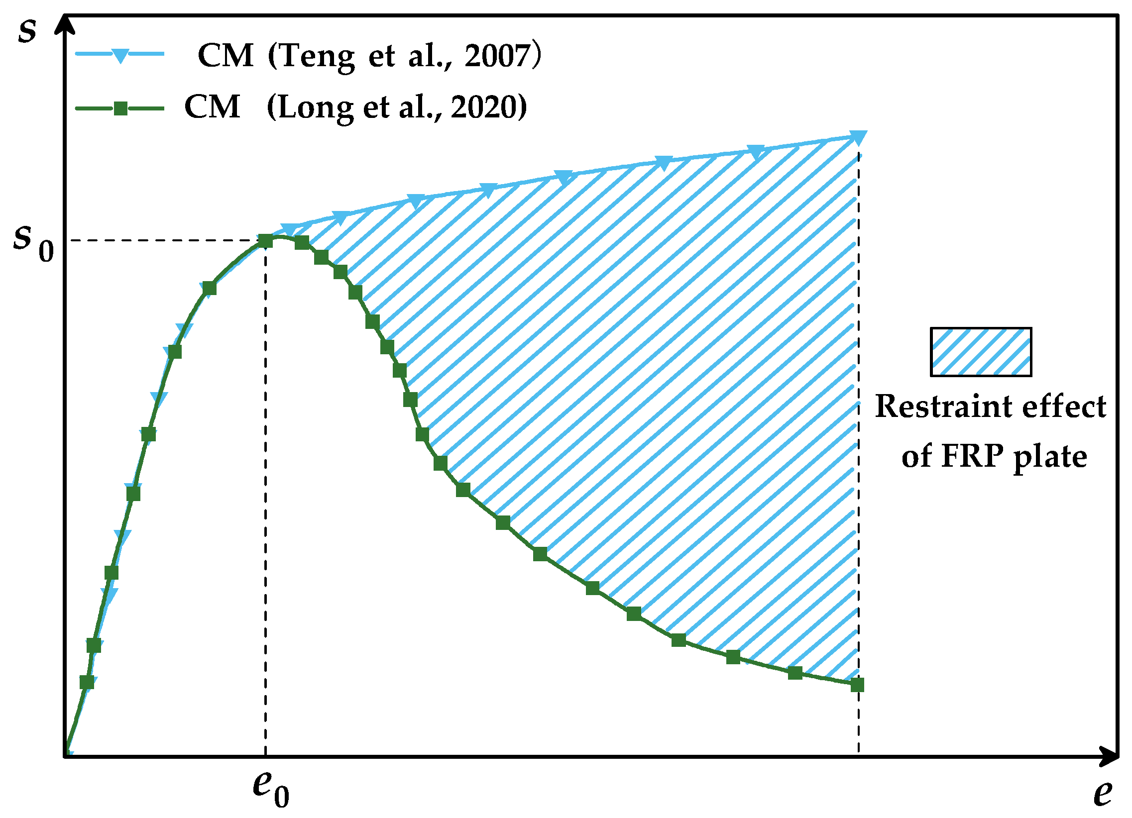
The constitutive model (CM) of concrete was studied by Long et al. [26] and Teng et al. [27], and the constitutive model of concrete is shown in Figure 4. Considering the constraint effect of the FRP, the CM for the RPC material is given by Teng et al. [27], which is adopted by Zhao et al. [28] and Lin et al. [29]. In this paper, the mechanical behavior of FRPCTs under gravity is analyzed. The strength grade of the RPC is C50 [30]. The specific parameters of materials of FRP are shown in Table 3.
The behavior of the RPC under compressive is given by Equation (6). The specific parameters are given in Equations (7) and (8).
σ c = E c ε c ( E c E 2 ) 2 4 f co ε c 2 ( 0 ε c ε t ) f co + E 2 ε c ( ε t ε c ε c c )
where σc represents the stress of the RPC under compressive strain when the strain of the RPC (ε) under compressive strain arrives at εc., Ec represents the initial modulus of elasticity, E2′ is the initial elastic modulus of the concrete, fco′ represents the axial compressive strength of the unconfined concrete, and εcc′ is the ultimate strain.
ε t = 2 f co E c E 2 E 2 = f cc f co ε cu
ε cu 0.002 = 1.75 + 12 f 1 f co ( ε h , rup ε co ) 0.45 f 1 = 2 E frp ε h , rup t D
where fcc′ represents the axial compressive strength of the confined concrete, and εh,rup represents the fracture strain of the FRP.

3.3. Element Selection and Contact

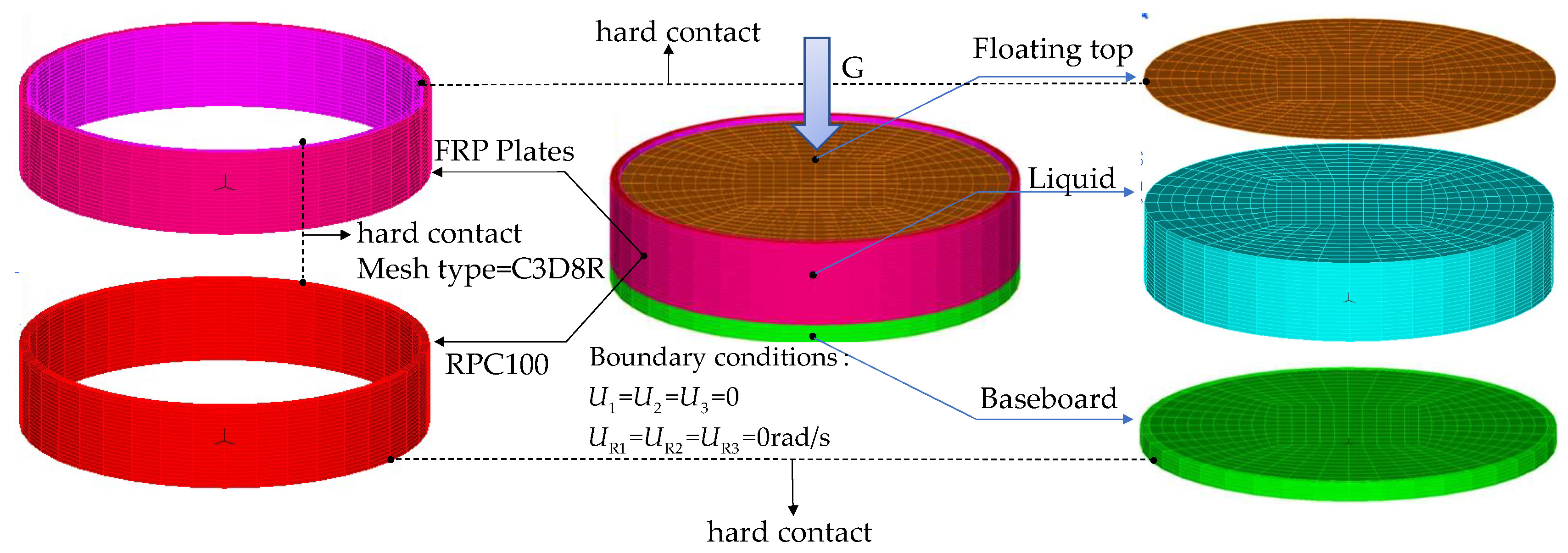
The eight-node solid element with reduced integration (C3D8R) is adopted for all parts of FEMs of FRPCTs. The CONTACT elements and TARGET elements matched with the SOLID elements are selected. The liquid surface is set as a free-surface fluid unit when considering the sloshing of the liquid storage, and the liquid surface is defined as a fluid–solid coupling element when considering the tank–liquid coupling. A flexible solid ring is adopted between the floating top and the tank wall. The contact between the FRP plate and RPC is defined as hard contact in the normal direction and a coulomb friction model in the tangential direction. The sliding contact is adopted between the floating top and the inner FRP plate. The interfacial contact of FRPCTs is shown in Figure 5.

3.4. Boundary Conditions and Mesh

While a boundary condition (U1 = U2 = U3 = UR1 = UR2 = UR3 = 0) is applied to the bottom plate [31], the gravity acceleration of 9.8 m/s2 is applied at the center of gravity. The mapped meshing is adopted to ensure mesh quality and calculation accuracy. The mesh shape is mainly hexahedral. The tank wall of FRPCTs below the liquid level is divided into 20 parts along the height direction, and 40 parts along the hoop direction, and the tank wall of FRPCTs above the liquid level is divided into two parts along the height direction. The inner and outer FRP plate is divided into one part along the thickness direction, and the RPC is divided into four parts along the thickness direction. The FEM of FRPCTs is shown in Figure 6.

4. FEM Verification

4.1. The Theoretical Verification of the FRPCTs without a Floating Top

Housner G. W., and Haroun M. A. [32,33] deduced the formula for calculating the natural vibration frequency of the liquid in the rigid cylindrical liquid storage structure through theoretical formula, as given by Equations (9) and (10), taking the inner diameter of FRPCT (D) and the height of tank liquid (Hw) as controlled parameters. The first-order natural frequency of liquid sloshing of FRPCT can be seen in Table 4.
w 2 = 27 8 g R tanh ( 27 8 h R )
w 1 S = tanh ( 1.84 h R ) 1.48 R
where w represents the natural frequency of the tank liquid. w1S represents the theoretical value of the first-order natural frequency of the tank liquid of FRPCTs without a floating top. g represents the acceleration of gravity. R and h represent the radius of the FRPCTs and the height of the FRPCTs, respectively.
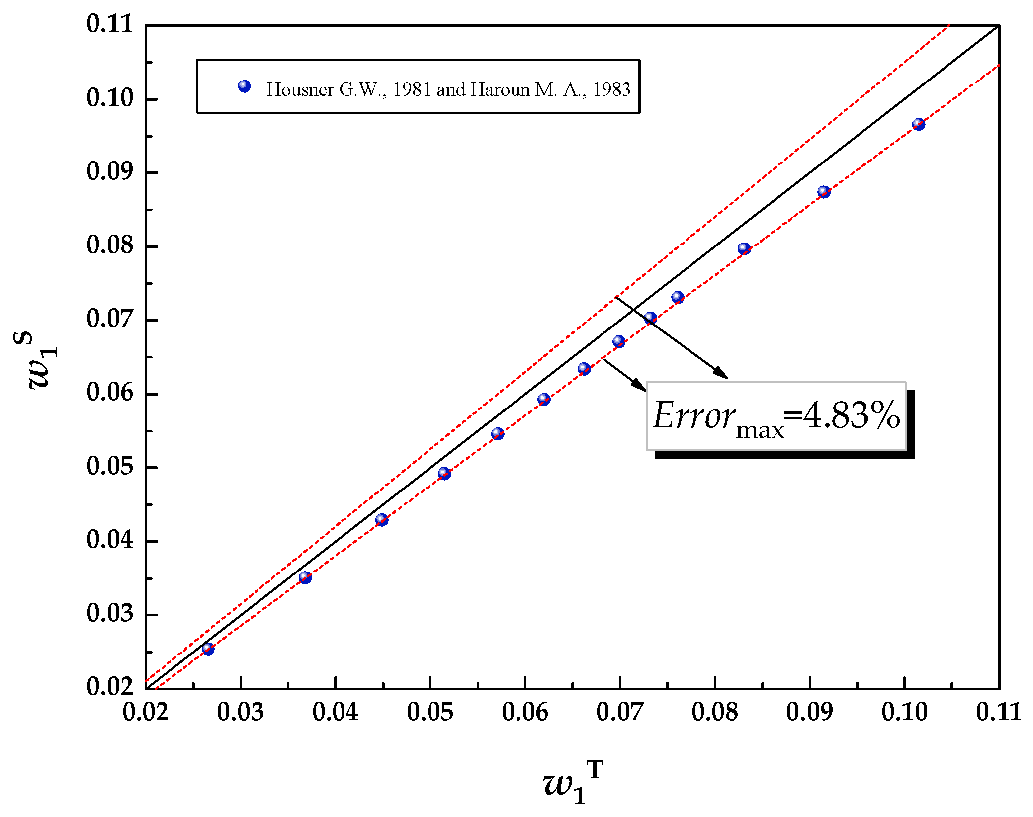
Based on the above modeling method, the 13 FEMs of FRPCTs are built according to API standard 650 [16], which is adopted by Li [24]. The mode analysis of the 13 FEMs of FRPCTs is carried out, and the FEMs are verified against the theoretical results in terms of the mode analysis. The comparisons of the first-order natural frequency of tank liquid of FRPCTs without a floating top between the calculation and the simulation are shown in Table 4. The mode of vibration of the T-FRPCT13 without a floating top is shown in Figure 7. The first-order vibration of the liquid of the T-FRPCT13 is slope-shape, and the second-order and third-order vibration of the liquid of the T-FRPCT13 is a groove shape and a basin shape, respectively. A good correlation between the theoretical and the FEM results is achieved in terms of the first-order natural frequency of the liquid sloshing of FRPCTs. The maximum error (Errormax) is 4.83% in Figure 8, indicating that the finite element model can better simulate the mechanical behavior of the FRPCTs.

4.2. The Test Validation of the LNG Storage Tank with a Floating Top

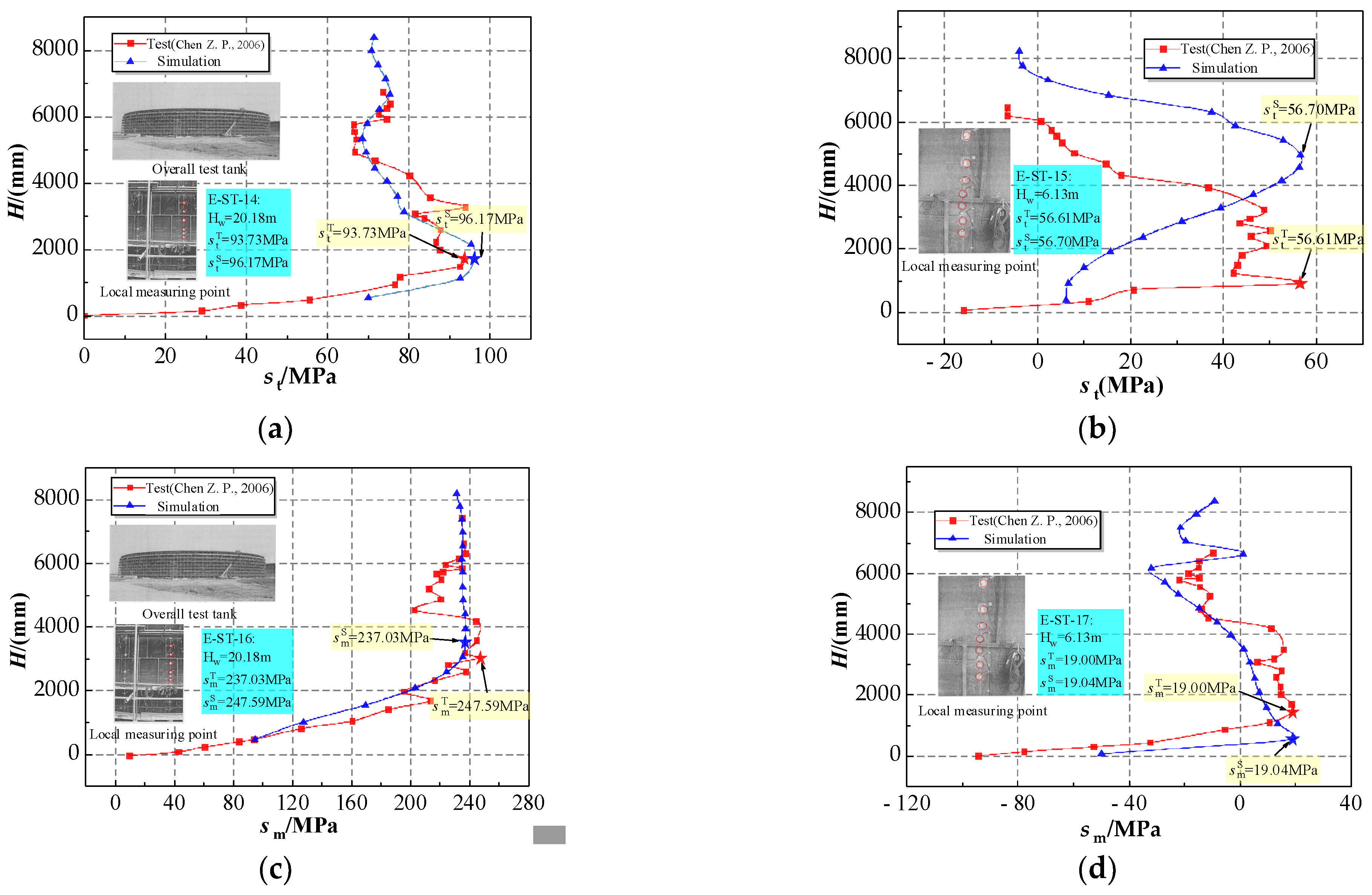
In order to verify the rationality of the modeling method of the FRPCTs with floating top, the FEMs for the mechanical behavior of the storage tank carried out by Chen et al. [34] are built. By comparisons with H-σt curves and H-σm curves with tests, H-σt curves and H-σm curves under the action of gravity can be obtained by simulation, which proves the rationality of adopting the modeling method of the storage tank with a floating top. The comparisons of four specimens are shown in Figure 9a–d. It can be seen that the trends of curves obtained by test and simulation remain consistent, and the peak stress can be accurately simulated. The hoop stress and axial stress of the storage tank simulated by the ADINA (σtS, σmS) and the hoop stress and the axial stress obtained by testing are compared in Table 5. It is analyzed that the maximum error (Errormax) is 4.27%, indicating that the modeling method of the storage tank has good application for the FRPCTs.

5. Parametrical Investigation

5.1. Influence of the Thickness of RPC (tc) on the Equivalent Stress

To comprehensively understand the mechanical behavior [35] of FRPCTs under gravity, a total of two designed parameters are considered in the numerical simulation [36,37]. Those are D and the tc. It can be obtained that the influences of different parameters on the stress distribution, equivalent stress, hoop stress, radial stress and axial stress of each part of FRPCT.

5.1.1. Influence of the Thickness of RPC (tc) on the Equivalent Stress with an Inner Diameter of the Storage Tank (D) of 100 m

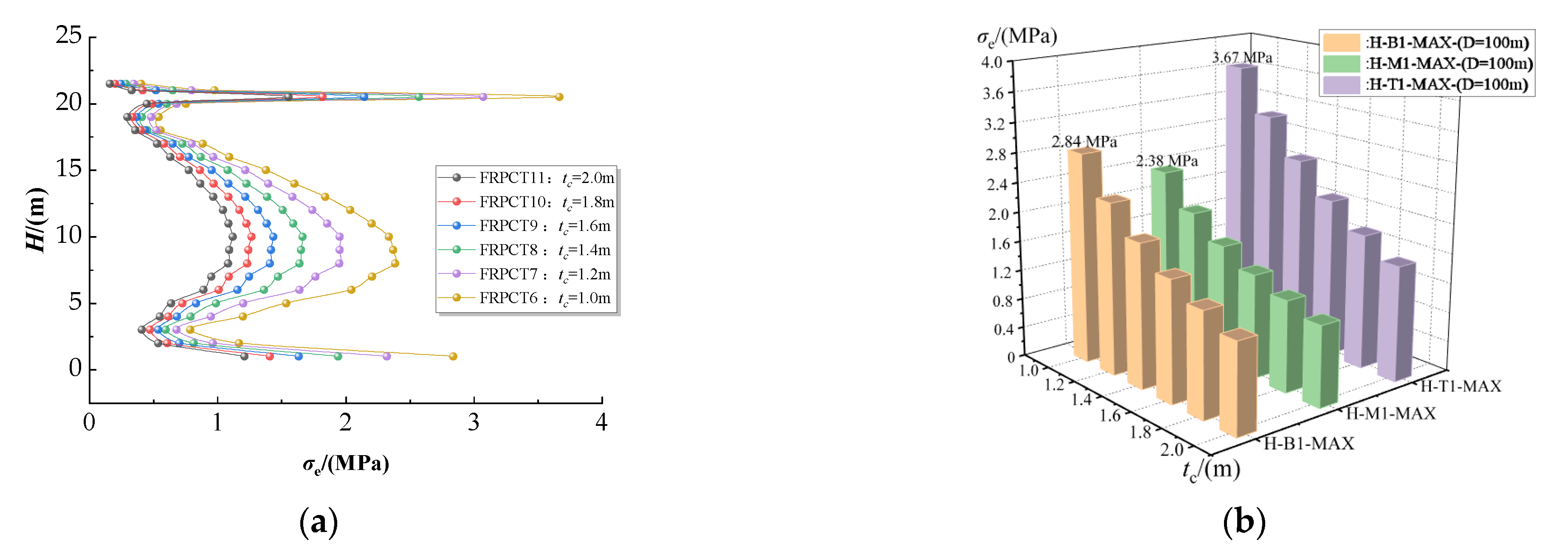
The influences of tc on the equivalent stress of the FRPCTs with an inner diameter of 100 m are simulated using different values of 1.0 m, 1.2 m, 1.4 m, 1.6 m, 1.8 m, and 2.0 m. The corresponding H-σe curves, σe-tc of FRPCTs with different tc, and the equivalent stress cloud diagram of FRPCTs are plotted in Figure 10. The peak equivalent stress of FRPCTs is shown in Table 6. The H-AB-MAX represents the location of the peak equivalent stress of the FRPCTs. Among them, “A” uses T, M, and B to determine the position of the peak equivalent stress of FRPCTs, and “B” uses 1, 2, 3, and 4 to determine the stress curves of different structural layers of the FRPCTs. Numbers 1, 2, 3, and 4 represent the inner FRP plate, the inner RPC, the outer RPC, and the outer FRP plate of the FRPCTs, respectively; T denotes the part of the tank wall at the height from 15 m to 21.5 m of FRPCTs; M represents the part of the tank wall at the height from 5 m to 15 m of FRPCTs, and B represents the part of the tank wall at the height from 0 m to 5 m of FRPCTs. For example, H-T1-MAX means the peak equivalent stress of the inner FRP plate at the height of the tank wall from 15 m to 21.5 m of FRPCTs.
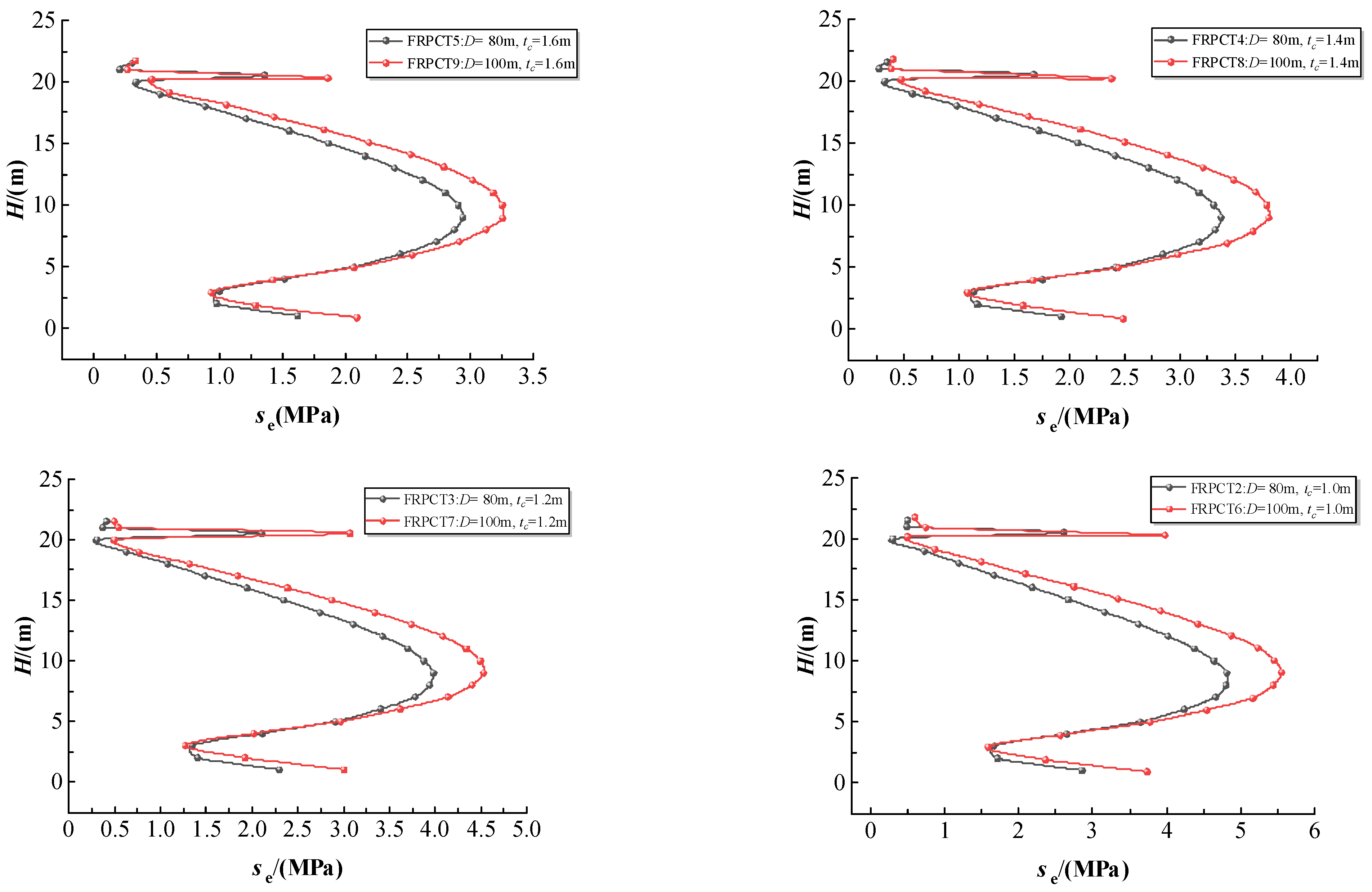
As seen in Figure 10a,b, when the values of the tc are given from 1.0 m to 2.0 m, the peak equivalent stress of the inner FRP plate (σ1max) can be decreased from 3.68 MPa to 1.55 MPa, which is reduced by 49.59%, as seen in Figure 10c,d, when the values of the tc are given from 1.0 m to 2.0 m, the peak equivalent stress of the inner RPC (σ2max) can be decreased from 5.45 MPa to 2.50 MPa, which reduces by 54.13%, as seen in Figure 10e,f, when the values of the tc are given from 1.0 m to 2.0 m, the peak equivalent stress of the outer RPC (σ3max) can be decreased from 5.15 MPa to 2.34 MPa, which reduces by 54.56%. As seen in Figure 10g,h, when the values of tc are given from 1.0 m to 2.0 m, the peak equivalent stress of the outer FRP plate (σ4max) can be decreased from 2.83 MPa to 1.19 MPa, which reduces by 57.95%. It can be seen that tc significantly influences the equivalent stress of FRPCT, and an increase in tc can indirectly reduce the equivalent stress of FRPCTs. With an increase in tc, the bearing capacity of FRPCTs increases. When the tc is more extensive than 1.4 m, a higher tc results in a less reduction in equivalent stress of FRPCT, which the increase in tc can explain, and the effective utilization rate of materials decreases.

5.1.2. Influence of the Thickness of RPC (tc) on the Equivalent Stress with an Inner Diameter of the Storage Tank (D) of 80 m

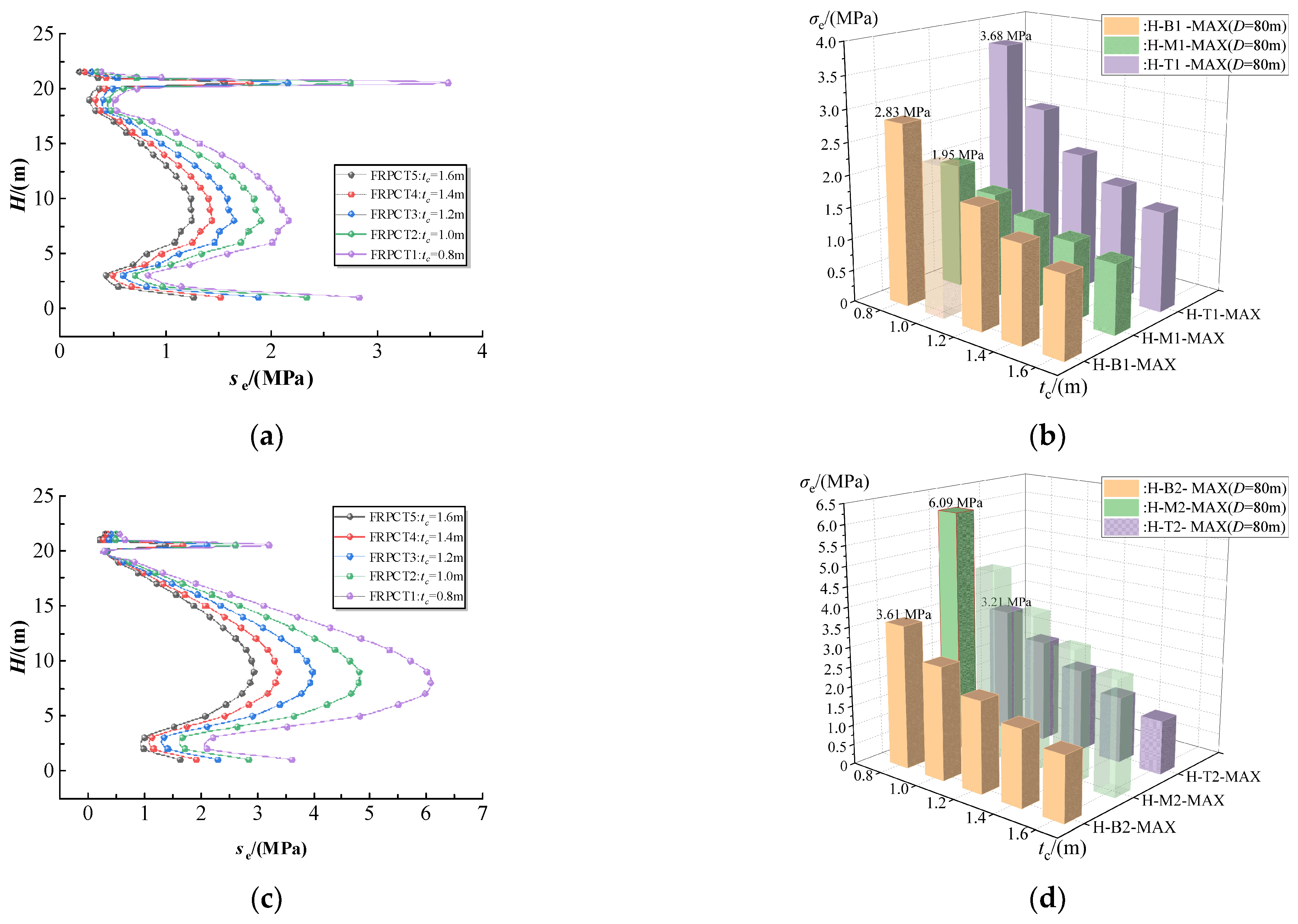
The influences of tc on the equivalent stress of the FRPCTs with an inner diameter of 80 m are simulated using different values of 0.8 m, 1.0 m, 1.2 m, 1.4 m, and 1.6 m. The corresponding H-σe curves and σe-tc of FRPCTs with the different tc are plotted in Figure 11, and the peak equivalent stress of FRPCTs is shown in Table 6. As seen in Figure 11a,b, when the values of tc are given from 0.8 m to 1.6 m, the σ1max can be decreased from 3.67 MPa to 1.55 MPa, which reduces by 49.48%, as seen in Figure 11c,d, the σ2max can be reduced from 6.08 MPa to 2.93 MPa, which decreases by 51.81%, as seen in Figure 11e,f, when the values of tc are given from 0.8 m to 1.6 m, the σ3max can be decreased from 5.14 MPa to 2.57 MPa, which reduces by 50.00%, and as seen in Figure 11g,h, when the values of tc are given from 0.8 m to 1.6 m, the σ4max can be decreased from 2.87 MPa to 1.32 MPa, which reduces by 54.01%. It can be summarized that the peak equivalent stress of the inner FRP plate appears at the top of the tank, and the peak equivalent stress of the inner RPC appears at the top of FRPCTs, which is the influence of the floating top on the tank wall. However, the equivalent stress of the outer RPC and the outer FRP plate reaches the peak stress at the bottom of FRPCTs, which is due to the effect of consolidation between the baseboard and the tank wall of FRPCTs.

5.1.3. Influence of the Thickness of the RPC (tc) on the Equivalent Stress with an Inner Diameter (D) of 120 m

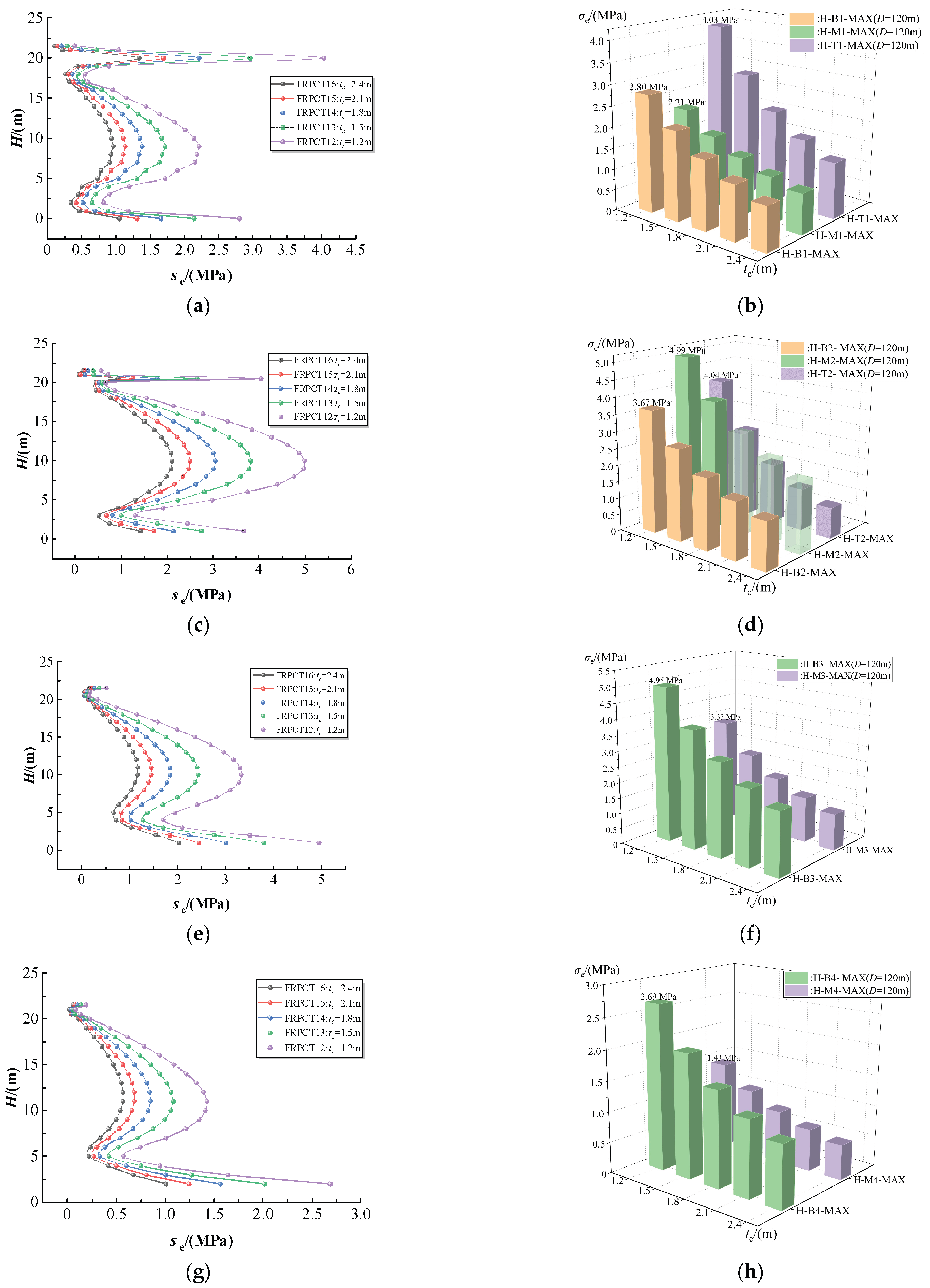
The influences of tc on the equivalent stress of the FRPCTs with an inner diameter of 120 m are simulated using different values of 1.2 m, 1.5 m, 1.8 m, 2.1 m, and 2.4 m. The corresponding H-σe curves and σe-tc of FRPCTs with different tc are plotted in Figure 12, and the peak equivalent stress of FRPCTs is shown in Table 6. As seen in Figure 12a,b, when the values of tc are given from 1.2 m to 2.4 m, the σ1max can be decreased from 4.03 MPa to 1.33 MPa, which reduces by 62.36%, as seen in Figure 12c,d, the σ2max can be reduced from 4.99 MPa to 2.10 MPa, which reduces by 57.92%, as seen in Figure 12e,f, when the values of tc are given from 1.2 m to 2.4 m, the σ3max could be decreased from 4.95 MPa to 2.04 MPa, which decreases by 58.79%, and as seen in Figure 12g,h, when the values of tc are given from 1.2 m to 2.4 m, the σ4max can be decreased from 2.69 MPa to 1.01 MPa, which reduces by 62.45%. It can be seen that the equivalent stress of the inner RPC changes slowly in the middle of the FRPCTs, and the trend of the equivalent stress of FRPCTs is similar when the inner diameter changes.

5.1.4. Influence of the Thickness of RPC (tc) on the Equivalent Stress with an Inner Diameter of the Storage Tank (D) of 150 m

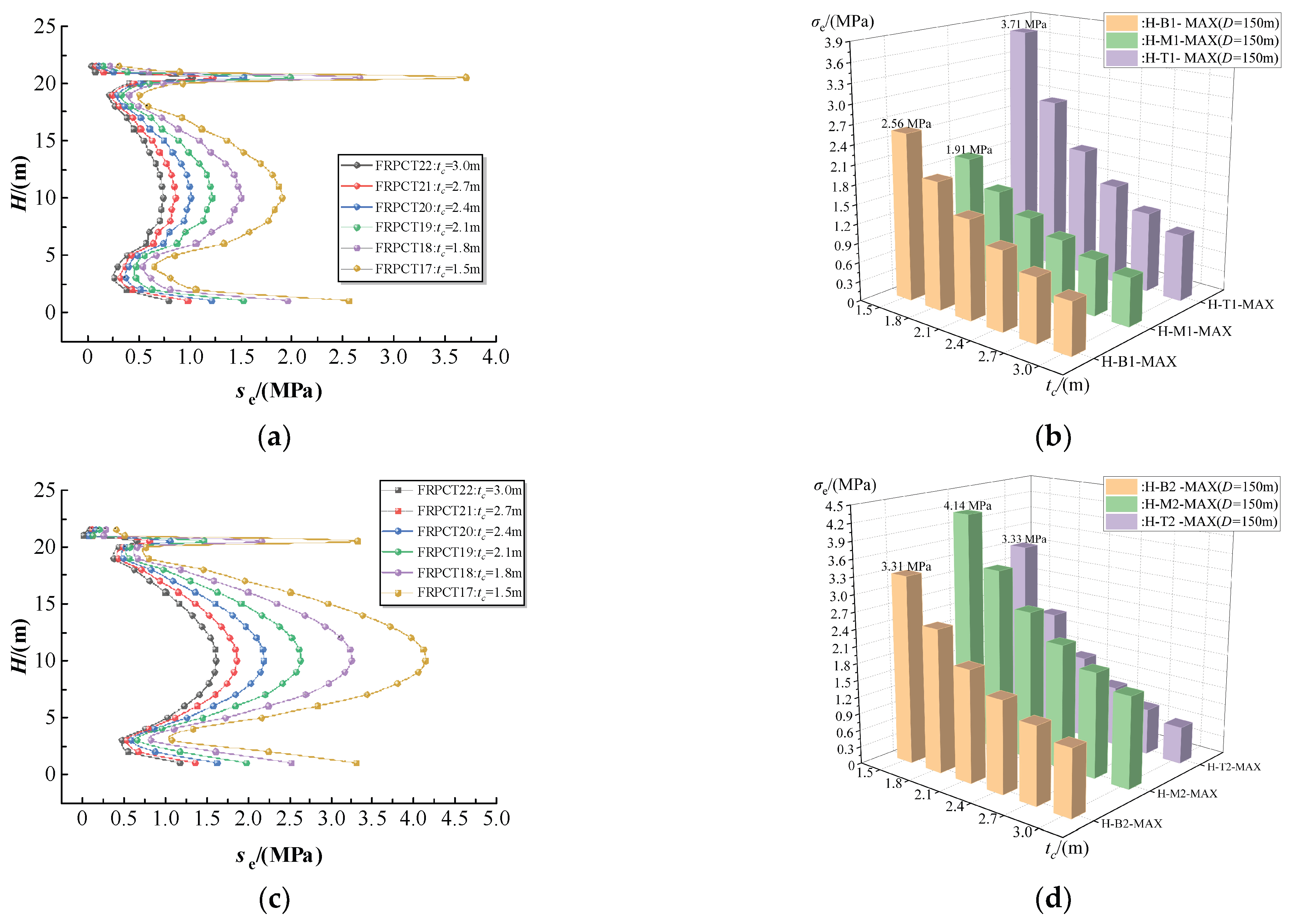
The influences of tc on the equivalent stress of the FRPCTs with an inner diameter of 150 m are simulated using different values of 1.5 m, 1.8 m, 2.1 m, 2.4 m, 2.7 m, and 3.0 m. The corresponding H-σe curves and σe-tc of FRPCT with different tc are plotted in Figure 13, and the peak equivalent stress of FRPCTs is shown in Table 6. As seen in Figure 13a,b, when the values of tc were given from 1.5 m to 3.0 m, the σ1max could be reduced from 3.71 MPa to 1.02 MPa, which reduced by 72.5%, as seen in Figure 13c,d, the σ2max could be reduced from 4.14 MPa to 1.61 MPa, which reduced by 61.11%, as seen in Figure 13e,f, when the values of tc were given from 1.5 m to 3.0 m, the σ3max could be reduced from 4.38 MPa to 1.58 MPa, which reduced by 63.93%, and as seen in Figure 13g,h, the σ4max could be reduced from 2.69 MPa to 1.01 MPa, which reduced by 62.45%. It can be seen that the equivalent stress of each part of FRPCTs is a W shape, the equivalent stress of the outer RPC and the outer FRP plate appear stress mutations. The stress mutations are more obvious with a reduction in tc. The equivalent stress of the inner FRP plate suddenly increases at the height of the tank wall of 20.5 m, and the equivalent stress of the outer RPC and the outer FRP plate suddenly increases at the bottom of FRPCTs.

5.2. Influence of the Thickness of RPC (tc) on the Hoop Stress

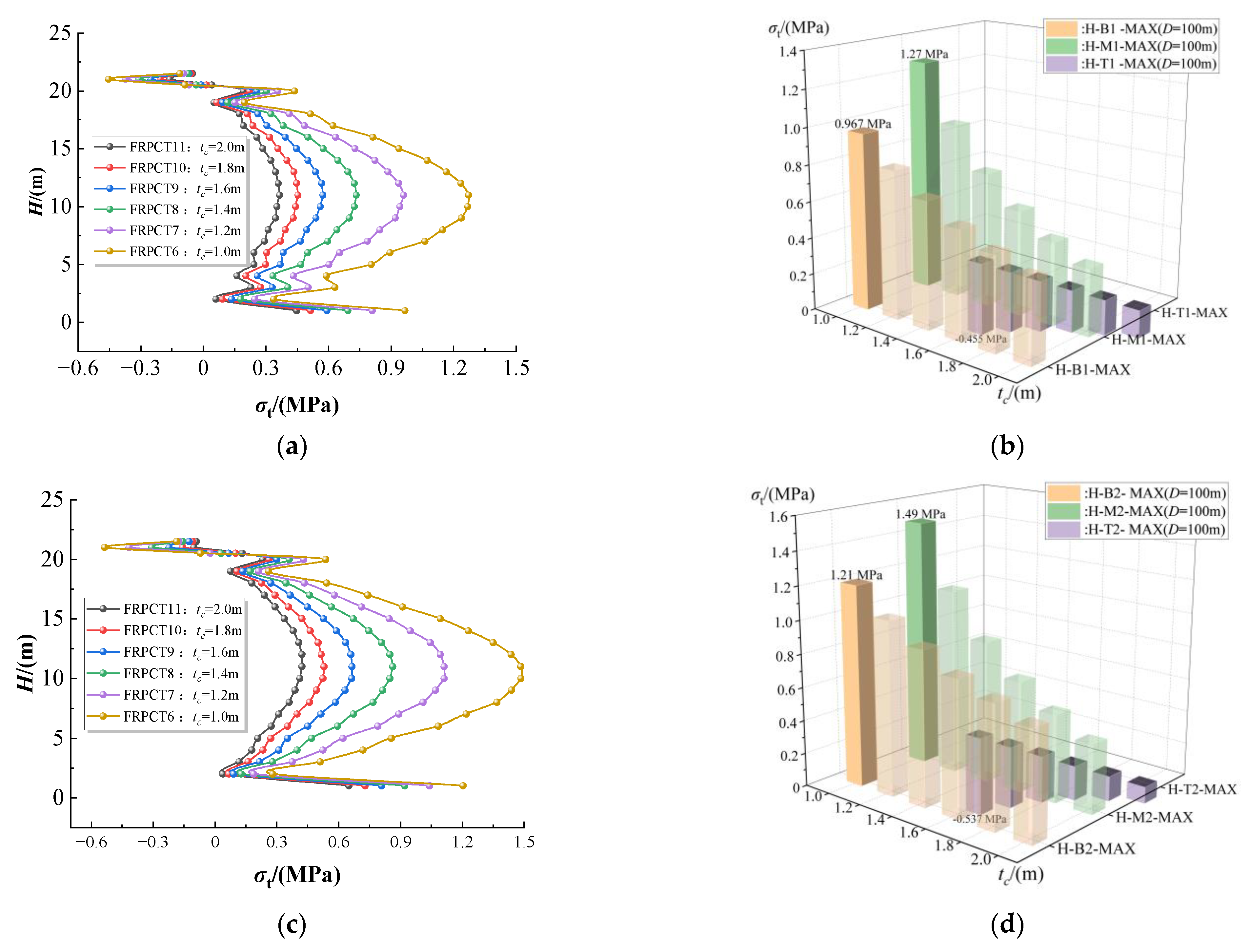
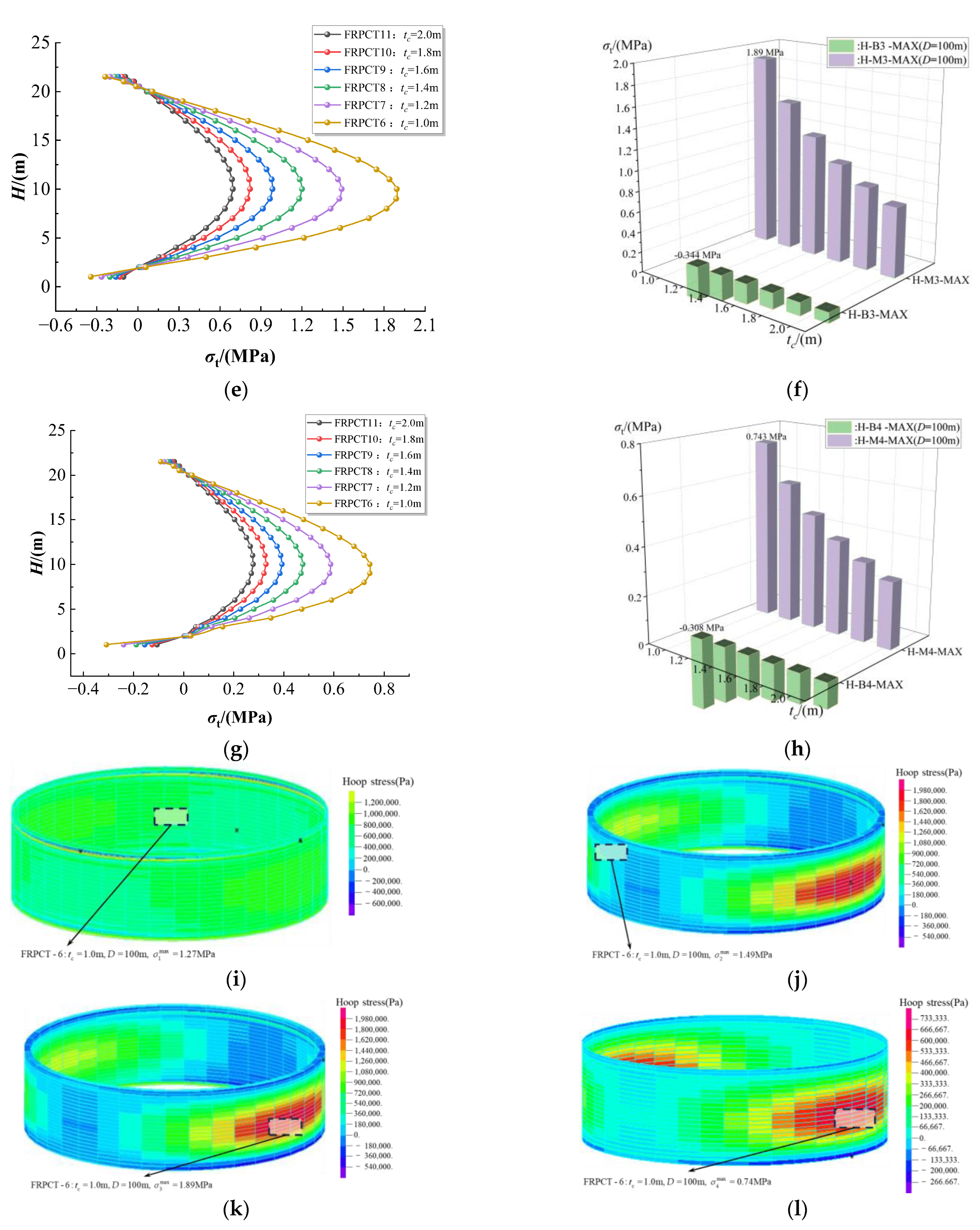
The influences of tc on the hoop stress of the FRPCTs with an inner diameter of 100 m are simulated using different values of 1.0 m, 1.2 m, 1.4 m, 1.6 m, 1.8 m, and 2.0 m. The corresponding H-σt curves and σt-tc of FRPCT are plotted in Figure 14. It can be seen that the top and bottom hoop stress of the inner FRP plate is complex. When the inner diameter is 1.0 m, the hoop stress of the inner FRP plate reaches the peak hoop tensile stress of 0.455 MPa and the hoop stress of the inner FRP plate and the inner RPC change from compressive stress to tensile stress at the height of the tank wall from 20 m to 19 m. The maximum difference value of hoop stress of the inner FRP plate is 0.88 MPa, and the stress mutation of the inner RPC is more obvious with a value of 1.06 MPa. It is found that tc greatly influences the variation in hoop stress. As seen in Figure 14a,c, at the same position, the hoop stress of the inner RPC is more significant than that of the inner FRP plate. The main reason is that the elastic modulus of the FRP is greater than that of concrete, and the RPC can effectively restrain the hoop deformation of the FRP plate. The changing trend of the hoop stress of the outer concrete and the outer FRP plate is consistent. The peak hoop stress of FRPCTs is 1.89 MPa in Figure 14, which is much less than the equivalent stress, so the hoop stress is not considered in this paper.

5.3. Influence of the Thickness of RPC (tc) on the Radial Stress

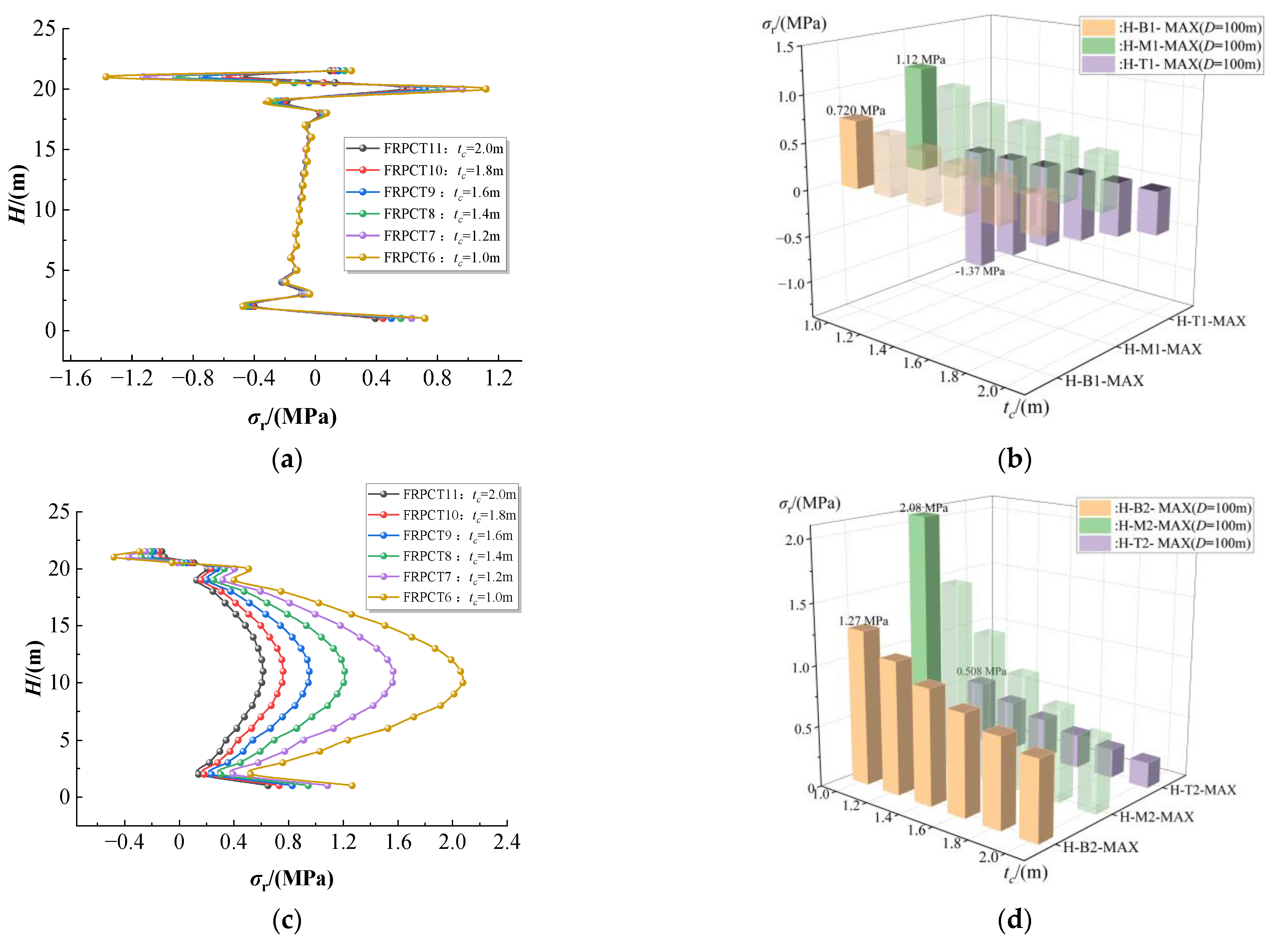
To illustrate the influence of tc on the radial stress of the FRPCTs with an inner diameter of 100 m, tc is set to five different values: 1.0 m, 1.2 m, 1.4 m, 1.6 m, 1.8 m, and 2.0 m. The corresponding σr-H curves and σr-tc of FRPCTs are plotted in Figure 15. Figure 15a,b shows that the radial compressive stress of the inner FRP plate reaches a maximum of 1.37 MPa, when tc is 1.0 m. Subsequently, the radial compressive stress of the RPC decreases slightly with an increase in tc and reaches a minimum of 0.470 MPa, when tc is 2.0 m. With an increase in tc, the radial stress of the inner FRP plate remains almost unchanged at the height from 3 m to 17.5 m, and with an increase in tc, the radial stress variation in the inner FRP plate fades away. The radial stress of the inner RPC reaches the peak value of 2.08 MPa at the height of 10 m, as shown in Figure 15c,d. It can be seen in Figure 15e, that the whole radial stress of the outer RPC and the outer FRP plate is in tensile stress, and the radial stress of the outer RPC and the outer FRP plate decreases with the increase in tc. Figure 15e shows that the radial compressive stress of the outer FRP plate reaches a maximum of 1.89 MPa, when tc is 1.0 m, and the radial stress of the outer RPC comes to a minimum of 0.696 MPa, when tc is 2.0 m. It can be summarized that with the increases in tc, the radial stress of each part of FRPCTs decreases gradually. The radial stress appears to be a stress mutation at the top of the inner FRP plate, and the radial stress of the inner FRP plate reaches the peak value of tensile stress of 1.37 MPa, which is much less than the ultimate tensile strength of FRP. Meanwhile, the radial stress of the outer FRP plate and outer RPC do not appear to stress mutation, so the radial stress of FRPCTs is not considered in this paper.

5.4. Influence of the Thickness of RPC (tc) on the Axial Stress

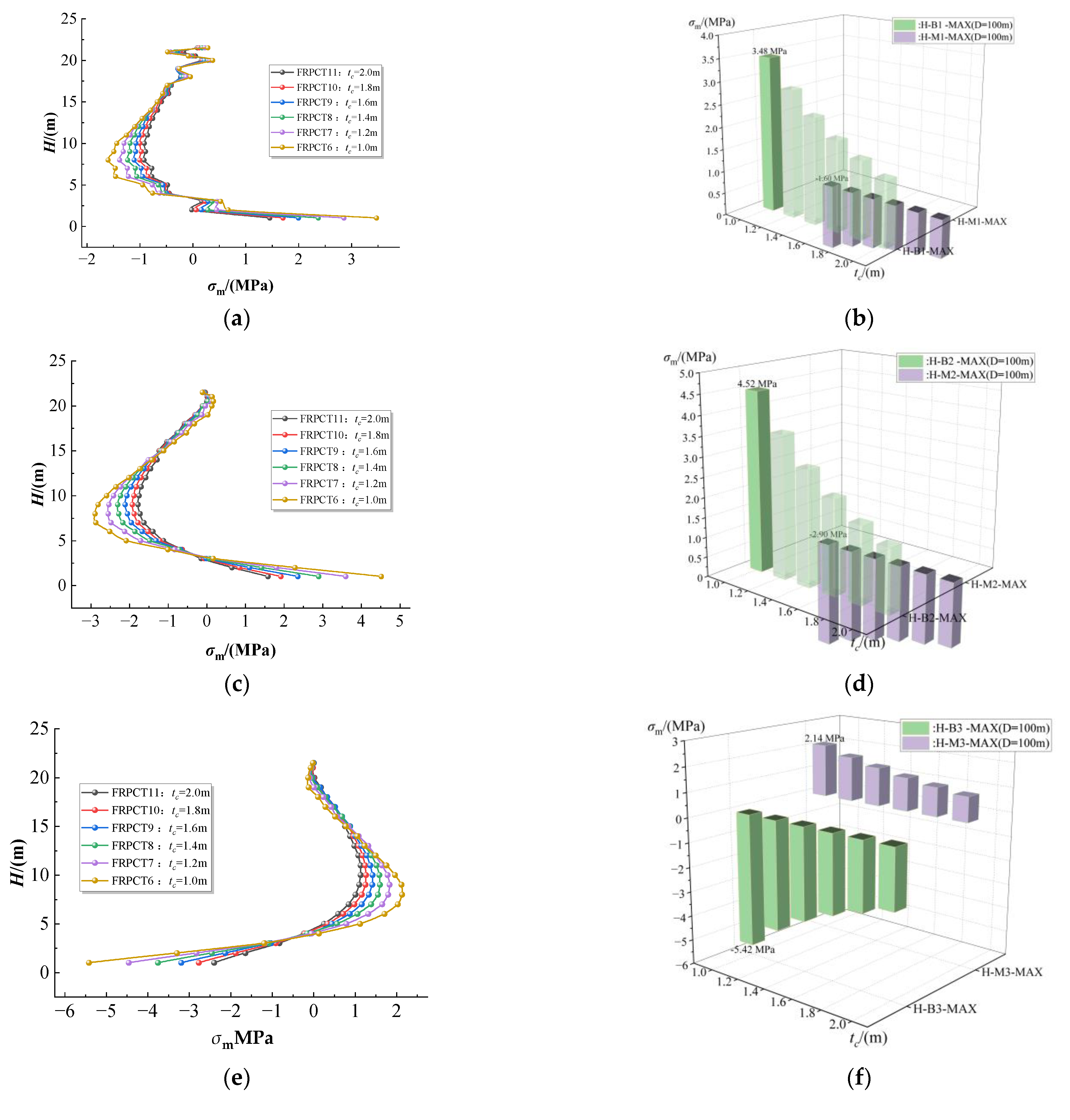
The influences of the tc on the axial stress of the FRPCTs with an inner diameter of 100 m are simulated using different values of 1.0 m, 1.2 m, 1.4 m, 1.6 m, 1.8 m, and 2.0 m. The corresponding H-σm curves and σm-tc of FRPCTs are plotted in Figure 16. Figure 16a shows that the stress variation in the inner FRP plate is complex at the top of FRPCTs. Figure 16c,d shows that the axial stress of FRPCT reaches the peak compressive stress of 4.52 MPa at the bottom of the inner RPC. Figure 16e,g shows that the axial stress of FRPCTs comes the peak tensile stress of 5.42 MPa at the bottom of the outer RPC. The reason for this situation is that the tank wall of FRPCTs is solidified with the baseboard. Moreover, with an increase in tc, the peak of compressive stress of each part of FRPCTs reduces gradually. Due to the material properties of the FRP, the axial stress needs to be considered. The peak axial compressive stress of inner RPC comes to 4.52 MPa, and the peak axial tensile stress reaches 5.42 MPa. The difference between the peak axial compressive stress and the peak tensile stress is large, so the axial stress of FRPCTs is considered in this paper.

5.5. Displacement Analysis on the FRPCTs

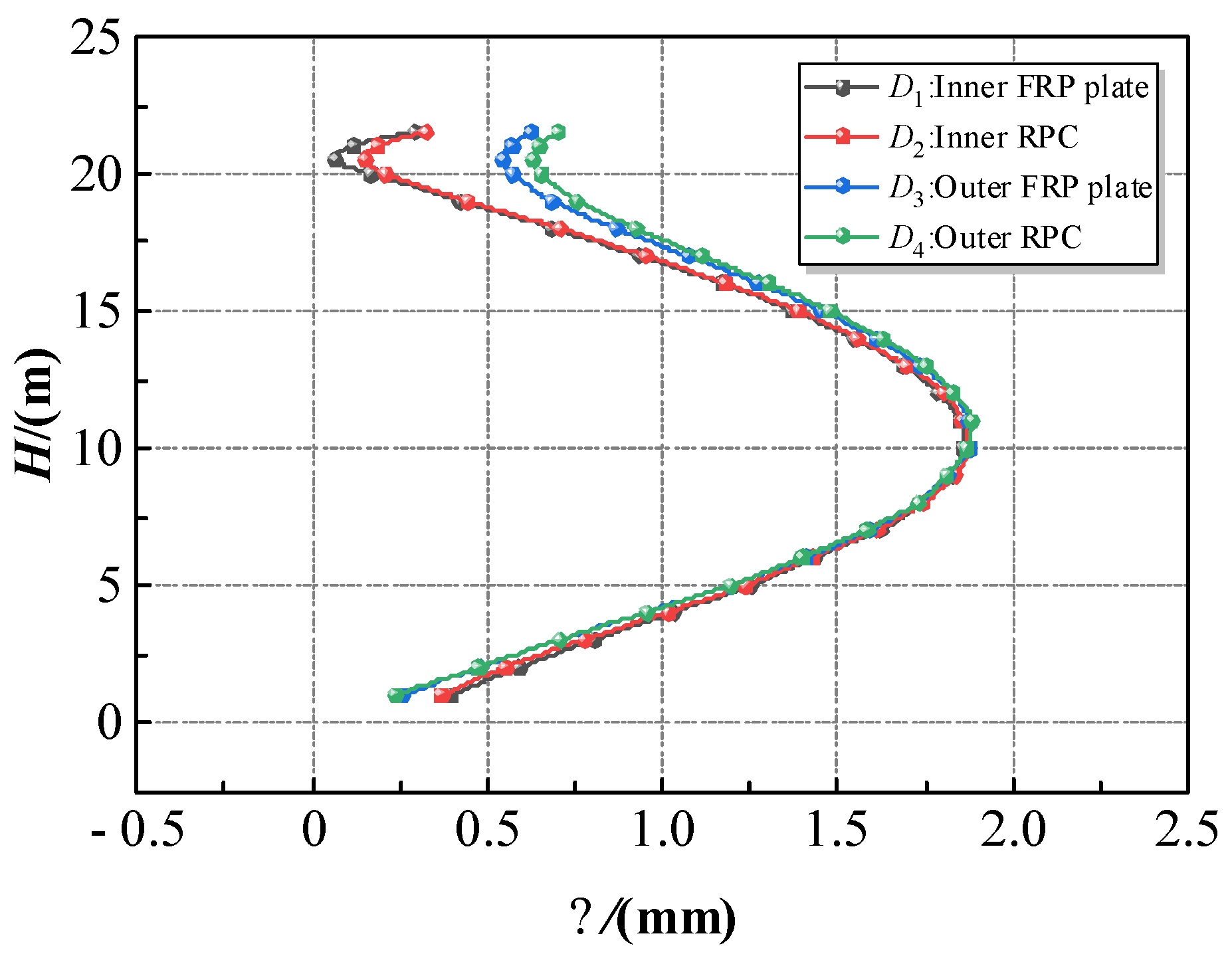
To reveal the force mechanism of FRPCTs, the numerical analysis of RPC and FRP plate is carried out. Taking the typical specimen (FRPCT6) as an example, the Δ-H curve of FRPCT6 is shown in Figure 17. The displacement of the bottom and top of the storage tank changes. The displacement of the storage tank at the height of 0 m varies from 0.26 mm to 0.40 mm, and the displacement of the storage tank at the height of 21.5 m ranges from 0.30 mm to 0.70 mm. The H-Δ curves of the inner FRP plate, the inner RPC, the outer FRP plate, and the outer RPC are almost coincident at 5 m to 20 m. The displacement of FRPCT reaches a maximum of 1.88 mm at the height of 10 m, which meets the structural design requirements. The displacement trend of different structural layers of the tank wall is consistent, which shows that the bonding between the FRP plate and the concrete is better. Hence, the influence of bond–slip between the FRP plate and the concrete can be neglected in the design of the FRP composite storage tank.

5.6. Influence of the Inner Diameter of the Storage Tank (D) on the Equivalent Stress

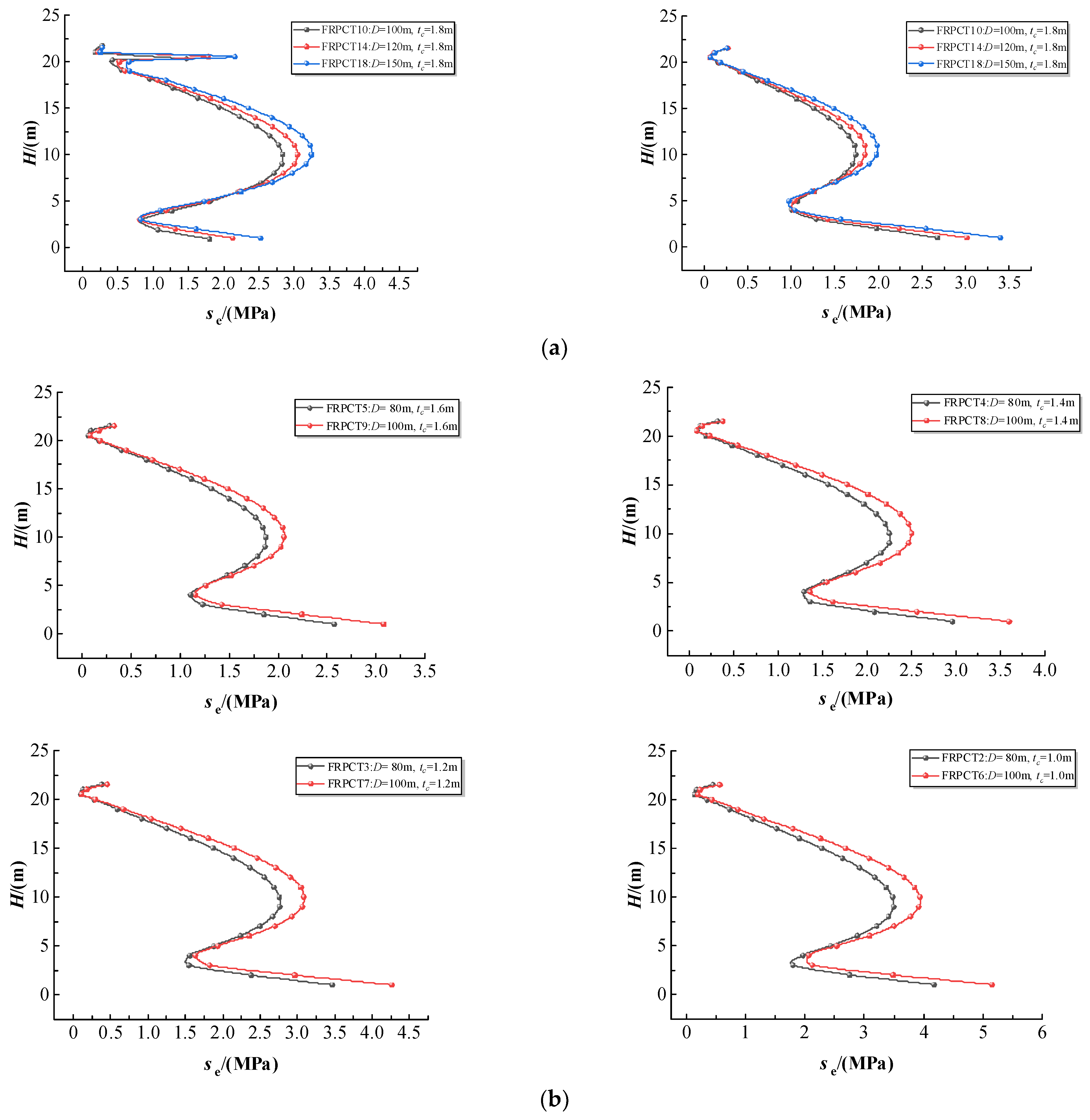
In this paper, the influence of D on the equivalent stress of FRPCT is studied using different values of 80 m, 100 m, 120 m, and 150 m. The corresponding H-σe curves are plotted in Figure 18. The equivalent stress of the inner RPC and the outer RPC changes abruptly at the bottom and top of the storage tank, which is due to the influence of the floating top and the base plate on the storage tank. The equivalent stress of the inner RPC reaches a maximum in the middle of the storage tank, which is due to the combined effects of the floating top and the liquid on the tank wall. It can be summarized that with the increase in D, the peak equivalent stress of FRPCT decreases.

5.7. Influence of the Inner Diameter of the Storage Tank (D) on the Axial Stress

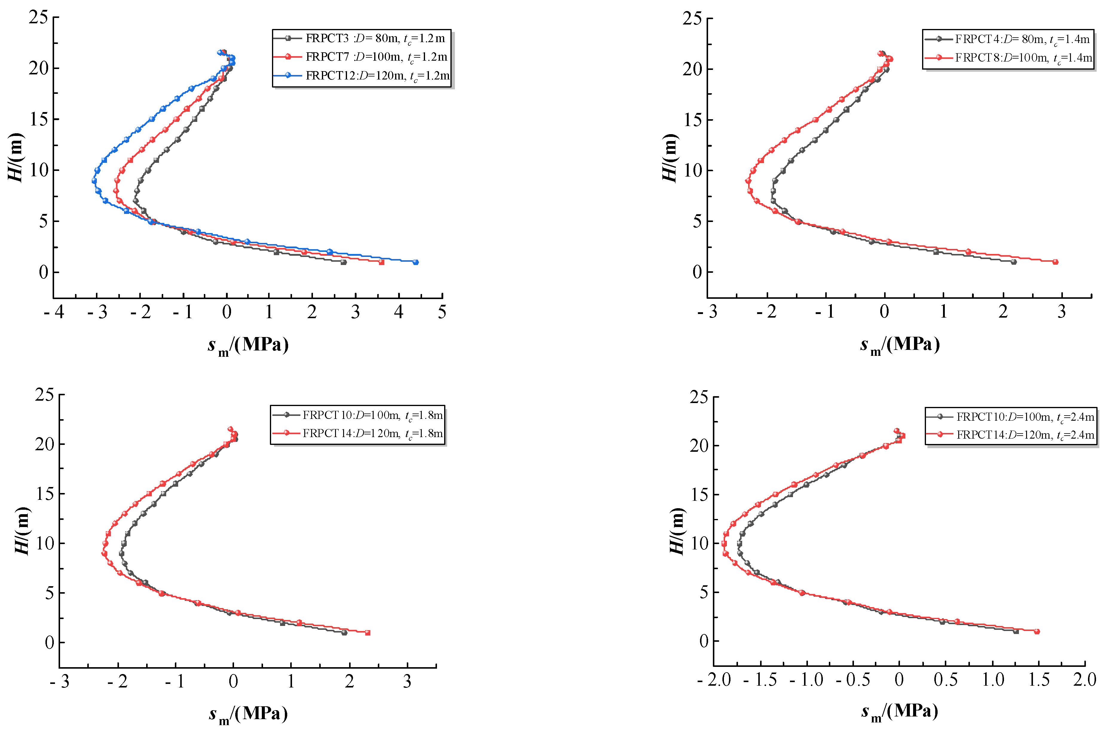
The effects of the D on the axial stress are simulated using different values of 80 m, 100 m, and 120 m. The corresponding H-σm curves are plotted in Figure 19. It is not difficult to find that with an increase in D, the volumes of the liquid storage quality increases. Hence, with an increase in D, the axial stress of inner RPC obviously increases. The axial stress of inner RPC is tensile stress at the height of 0 m to 5 m. However, the axial stress of the inner RPC is mainly compressive stress at the height of 5 m to 21.5 m. The reason for this is the connection between the tank wall and the baseboard. The baseboard shares part of the stress of the liquid on the bottom of the tank wall.

6. Discussion

6.1. Force Mechanism

To reveal the force mechanism of FRPCT, the numerical analysis of RPC and FRP plate is carried out. Taking the typical specimen (FRPCT11) as an example, the H-σe curves of the inner FRP plate, the inner RPC, the outer RPC, and the outer FRP plate are a horizontal W shape distribution, and the direction of the curves is consistent. It is shown that there is a sudden change in the equivalent stress at the bottom and top of FRPCTs. The H-σt curves of the inner FRP plate, the inner RPC, the outer RPC, and the outer FRP plate are a horizontal U-shape distribution, and the direction of the curves is consistent. The H-σr curves of the inner FRP plate are an I-shape distribution, but the curves of the inner RPC, the outer RPC, and the outer FRP plate are a horizontal U-shape distribution. The H-σm curves of the inner FRP plate and the inner RPC are a U-shape distribution with an opening to the left, but the axial stress-H curves of the outer FRP plate and outer RPC are a U-shape distribution with an opening to the right. The essential reason is the consolidation between the tank wall and the base plate.
According to numerical analysis of 22 FRPCTs, the stress distribution of inner RPC and outer RPC are obtained. The equivalent stress of inner RPC reaches a maximum at the top of FRPCTs, and the axial stress reaches a maximum at the bottom of FRPCT. The equivalent stress of outer RPC reaches a maximum at the bottom of FRPCT. The peak stress of FRPCT is shown in Table 7.

6.2. Theoretical Formula of the Tank Wall Composition

The formula [38] to calculate the axial tensile strength standard value of RPC (ftk) is:
f tk = 1.77 f cu , k , 70 . 7 11.7
where fcu,k,70.7 represents the cubic compressive strength standard value of the RPC with a side length of 70.7 mm
The fcu,k,70.7 of the RPC is 100 MPa, and the ftk is 7.1 MPa [39]. The stress boundary of FRPCTs is selected from the value of 1/3 ftk to 1/2 ftk. Therefore, it has been calculated that the FRPCTs are considered to be damaged, when the stress of the tank wall exceeds 3.3 MPa in this paper. For the diameters of 80 m and 100 m of FRPCTs, the tc is 1.6 m, which meets the specification. For the diameters of 120 m of FRPCTs, the tc is 1.8 m, which meets the specification. For the diameters of 150 m of FRPCTs, the tc is 2.1 m, which meets the specification. Based on the statistical calculation software, the parameters are regressed. The calculation formula for the variation regularity of the tc is developed with the different D, as shown in Equation (12).
B H = t f 1 + t c + t f 2 = t f 1 + 10 4 D 2 0.0148 D + 2.1513 + t f 2 = 10 4 D 2 0.0148 D + 2.3513
where tf1 and tf2 represent the thickness of the inner FRP plate and the thickness of the outer FRP plate, which is taken as 0.1 m. tc is the thickness of the RPC.
The calculation formula for the variation regularity of the tc is compared with the numerical simulation results in Figure 20. It is noted that the R2 is 0.9836, indicating that the formulae can be adopted to calculate the tc of FRPCTs, which can provide a reference for the preliminary design in practical engineering.

6.3. Design and Construction Suggestion for FRPCTs

The stress distribution of FRPCTs with a floating top under gravity is studied and discussed in this paper. More in-depth research on the other behavior of FRPCTs needs to be carried out. The design suggestion for the FRPCTs can be carried out from the following aspects, as shown in Figure 21.
(1)
To solve the design problem of wall thickness, the calculation formula for the variation regularity of the tc is developed with the different D in this paper. The appropriate wall thickness can ensure the material utilization and safety of FRPCTs.
(2)
In order to ensure the stiffness of the baseboard, it is suggested that the baseboard be poured with reinforced reactive powder concrete [40]. The influence of uneven settlement of the foundation on the baseboard is a severe problem, which is the main reason for structural failure. In the future, the form of the baseboard of the storage tank can be carried out to enrich the study of the storage tank. Due to the rounding effect, the internal pressure of the storage tank is specific to the bolt tension. In order to achieve the overall stability of the tank wall and the baseboard, the M64 bolt is adopted in Figure 21c,d.
(3)
The floating top is connected with the tank wall by the sealing rubber trap, which is placed in the groove of the floating top, and the upper slideway and the lower slideway are fixed at the design-in location to ensure gas tightness. The floating top slides into the tank, and the reserve vent removes gas below the floating top. The sketch of the floating top is shown in Figure 21a,b.
(4)
The layered construction method was used to construct the tank walls. First, the FRP precast plates are spliced through rivets, and the connection for the FRP plate is bonded along the circumference between the inner FRP plate and the outer FRP plate. Then, the RPC is poured between the inner FRP plate and the outer FRP plate, and one layer is completed to construct the next layer until the tank wall of the FRPCTs is finished. At last, the ring beam is built to improve the overall stability of the storage tank.

7. Conclusions

In this paper, combined with the RPC and the structure of the composite storage tank, 22 specimens of FRPCTs are designed, and the stress distribution of FPRCTs is analyzed. The main findings of the study are summarized below.
  • In the case of the full tank, the equivalent stress of the inner FRP plate and the inner RPC occurs stress mutation at the top and bottom of the tank. The equivalent stress of the inner FRP plate reaches a peak value at the top of the tank. The equivalent stress of the inner FRP plate, inner RPC, outer RPC, and outer FRP plate uniformly changes at the middle of FRPCTs, and the equivalent stress of outer RPC and outer FRP plate reaches the peak equivalent stress at the bottom of FRPCTs. The distribution of equivalent stress of FRPCT is horizontal W-shaped, and the peak equivalent stress of inner RPC appears in the middle of FRPCTs.
  • Due to the influence of the floating top, the hoop stress, radial stress, and axial stress exhibit complexity of stress distribution at the top of FRPCTs. Among them, the radial stress of the inner FRP plate causes mutation at the top of FRPCTs. Compared with traditional steel storage tanks, due to the FRP characteristic of high tensile strength, the deformation of FRPCTs is less prone to buckling at the top of the storage tank.
  • The equivalent stress, hoop stress, radial stress, and axial stress of FRPCT decrease with an increase in tc. Furthermore, the tc positively affects the stress mutation, and with an increase in tc, the magnitude of the stress change is significantly reduced. Especially, the radial stress mutation of the inner FRP plate is improved obviously with the increase in tc. By comparison of the stress distribution of inner RPC with different D, the equivalent stress and axial stress increase with an increase in D. However, the effect of D on the axial stress of the FRPCTs is slight.
  • The displacement of the inner FRP plate, inner RPC, outer FRP plate, and outer RPC have a good agreement. In the case of the full tank, there is no obvious dislocation between the FRP and RPC. Therefore, the bond–slip between the FRP and RPC can be neglected. The concentric double-layer FRP plate can be used as a template to pour concrete, which has economic efficiency.
  • Based on the stress distribution acquired through the static analysis of FRPCTs, the calculation formula for the variation regularity of the tc is developed, and the design suggestion for this kind of novel tank is proposed correspondingly. The findings of the numerical simulation results agree with the calculation formula for the variation regularity of the tc obtained by polynomial fitting, indicating that the calculation formula for the variation regularity of the tc is reasonable and feasible.

Author Contributions

Conceptualization, J.J.; software, Y.L. and H.Z.; validation, L.J. and K.Y.; writing—original draft, J.J., H.Z. and L.J.; writing—review and editing, K.Y. and Z.Z.; resources, J.J. and K.Y.; data curation, X.C.; supervision, J.J. and J.L.; project administration, J.J.; funding acquisition, J.J. All authors have read and agreed to the published version of the manuscript.

Funding

This work is supported by the Joint Guidance Project of the Natural Science Foundation of Heilongjiang Province (No. LH2020E018), Scientific Research Fund of the Institute of Engineering Mechanics of China Earthquake Administration (No. 2020D07), China-Pakistan Belt and Road Joint Laboratory on Smart Disaster Prevention of Major Infrastructures (No. 2022CPBRJL-05), Northeast Petroleum University Guided Innovation Fund (No. 2020YDL-02), Guiding Science and Technology Project of Daqing City (No. zd-2021-40).

Data Availability Statement

The data used to support the findings of this study are included within the article.

Conflicts of Interest

The authors declare that the research was conducted in the absence of any commercial or financial relationships that could be construed as a potential conflict of interest.

References

  1. Pouyakian, M.; Jafari, M.J.; Laal, F.; Nourai, F.; Zarei, E. A comprehensive approach to analyze the risk of floating roof storage tanks. Process Saf. Environ. Prot. 2021, 146, 811–836. [Google Scholar] [CrossRef]
  2. Yasunaga, J.; Uematsu, Y. Dynamic buckling of cylindrical storage tanks under fluctuating wind loading. Thin-Walled Struct. 2020, 150, 106677. [Google Scholar] [CrossRef]
  3. Zhao, Y.; Li, H.N.; Zhang, S.C.; Mercan, O.; Zhang, C.Y. Seismic analysis of a large LNG tank considering different site conditions. Appl. Sci. 2020, 10, 8121. [Google Scholar] [CrossRef]
  4. Cortes, G.; Prinz, G.S. Seismic fragility analysis of large unanchored steel tanks considering local instability and fatigue damage. Bull. Earthq. Eng. 2017, 15, 1279–1295. [Google Scholar] [CrossRef]
  5. Feng, Y.; Yang, Y.; Huang, B. Corrosion analysis and remaining useful life prediction for storage tank bottom. Int. J. Adv. Robot. Syst. 2019, 16, 172988141987705. [Google Scholar] [CrossRef]
  6. Cwirzen, A.; Penttala, V.; Vornanen, C. Reactive powder based concretes: Mechanical properties, durability and hybrid use with OPC. Cem. Concr. Res. 2008, 38, 1217–1226. [Google Scholar] [CrossRef]
  7. Lee, P.N.; Fry, J.S.; Forey, B.A. A review of the evidence on smoking bans and incidence of heart disease. Regul. Toxicol. Pharmacol. 2014, 70, 7–23. [Google Scholar] [CrossRef]
  8. Soupionis, G.; Georgiou, P.; Zoumpoulakis, L. Polymer composite materials fiber-reinforced for the reinforcement/repair of concrete structures. Polymers 2020, 12, 2058. [Google Scholar] [CrossRef]
  9. Saleem, S.; Pimanmas, A.; Rattanapitikon, W. Lateral response of PET FRP-confined concrete. Constr. Build. Mater. 2018, 159, 390–407. [Google Scholar] [CrossRef]
  10. Tafsirojjaman, T.; Ur Rahman Dogar, A.; Liu, Y.; Manalo, A.; Thambiratnam David, P. Performance and design of steel structures reinforced with FRP composites: A state-of-the-art review. Eng. Fail. Anal. 2022, 138, 106371. [Google Scholar] [CrossRef]
  11. Sanjuán M, Á.; Andrade, C. Reactive powder concrete: Durability and applications. Appl. Sci. 2021, 11, 5629. [Google Scholar] [CrossRef]
  12. Venkatasudhahar, M.; Velu, R.; Dilip Raja, N.; Logesh, K. Experimental investigation on natural fibre composite for thermal insulation performance enhancement. Int. J. Ambient Energy 2020, 41, 1304–1307. [Google Scholar] [CrossRef]
  13. Beaufait, F.W.; Ioannides, S.A.; Gerlein, M.A. Analysis of shell walls of circular tanks under axisymmetrical pressure. Comput. Struct. 1979, 10, 531–538. [Google Scholar] [CrossRef]
  14. Balendra, T.; Ang, K.K.; Paramasivam, P.; Lee, S.L. Seismic design of flexible cylindrical liquid storage tanks. Earthq. Eng. Struct. Dyn. 1982, 10, 477–496. [Google Scholar] [CrossRef]
  15. API Standard 650; Welded Tanks for Oil Storage. 12th ed. American Petroleum Institute: Washington, DC, USA, 2013.
  16. Azzuni, E.; Guzey, S. Comparison of the shell design methods for cylindrical liquid storage tanks. Eng. Struct. 2015, 101, 621–630. [Google Scholar] [CrossRef]
  17. Malhotra, P.K.; Wenk, T.; Wieland, M. Simple procedure for seismic analysis of liquid-storage tanks. Struct. Eng. Int. 2000, 10, 197–201. [Google Scholar] [CrossRef]
  18. Huang, M.; Chen, G.; Yang, P.; Hu, K.; Zhou, L.X.; Men, J.K.; Zhao, J. Multi-hazard coupling vulnerability analysis for buckling failure of vertical storage tank: Floods and hurricanes. Process Saf. Environ. Prot. 2022, 161, 528–541. [Google Scholar] [CrossRef]
  19. Jhung, M.J.; Kang, S.-S. Fluid effect on the modal characteristics of a square tank. Nucl. Eng. Technol. 2019, 51, 1117–1131. [Google Scholar] [CrossRef]
  20. Wang, L.L.; Fu, S.B.; Qiao, H.Y. Simplified finite element model for static analysis of vertical storage tank. Oil Gas Storage Transp. 2021, 40, 51–57. [Google Scholar]
  21. De Angelis, M.; Giannini, R.; Paolacci, F. Experimental investigation on the seismic response of a steel liquid storage tank equipped with floating roof by shaking table tests. Earthq. Eng. Struct. Dyn. 2009, 39, 377–396. [Google Scholar] [CrossRef]
  22. Luo, D.Y.; Liu, C.G.; Sun, J.G.; Cui, L.F.; Wang, Z. Sloshing effect analysis of liquid storage tank under seismic excitation. Structures 2022, 43, 40–58. [Google Scholar] [CrossRef]
  23. Wang, M.Z.; Sun, Z.G.; Sun, J.G.; Cui, L.F.; Wu, Y.J. Probabilistic seismic fragility assessment of vertical storage tank with a floating roof. Structures 2023, 48, 318–330. [Google Scholar] [CrossRef]
  24. Li, K.N. The Nonlinear Analysis on Underground Reinforced Concrete Oil Tank; Beijing University of Aeronautics and Astronautics: Beijing, China, 2011. [Google Scholar]
  25. Du, Y.K. Dynamic Characteristics and Seismic Behavior of Large Inground Liquid Storage Tanks; Beijing University of Aeronautics and Astronautics: Beijing, China, 2006. [Google Scholar]
  26. Long, P.H.; Huang, L.Y.; Qiao, H.; Song, H.; Li, F. RPC constitutive relation and ultimate flexural capacity of rectangular RPC beams. China Concr. Cem. Prod. 2020, 10, 55–60. [Google Scholar]
  27. Teng, J.G.; Huang, Y.L.; Lam, L.; Ye, L.P. Theoretical model for fiber-reinforced polymer-confined concrete. J. Compos. Constr. 2007, 11, 201–210. [Google Scholar] [CrossRef]
  28. Zhao DZhang JG Liu FF Zhao GL Gu CZhang WC Song, H.Y. Experimental study of the behavior under axial compression of steel tube confined concrete with a circular hollow section (STCC-CHS). Ocean Eng. 2023, 285, 115267. [Google Scholar]
  29. Lin, H.W.; Zeng, H.X.; Feng, P.; Jiang Cheng, J.; Zhang, Y.Q. Bond behavior of FRP-concrete wet-bonding interface under lateral confinement. Eng. Struct. 2023, 292, 116536. [Google Scholar] [CrossRef]
  30. Liu, Y.; Xiao, L.; Yang, F.; Zhang, B.C.; Huang, H. Static analysis of 160000 cubic meters LNG storage tank. Port Eng. Technol. 2020, 57, 85–90. [Google Scholar]
  31. Ji, J.; He, L.J.; Jiang, L.Q.; Zhang, Y.F.; Liu, Y.C.; Li, Y.H.; Zhang, Z.B. Numerical study on the axial compression behavior of composite columns with steel tube SHCC flanges and honeycombed steel web. Eng. Struct. 2023, 283, 115883. [Google Scholar] [CrossRef]
  32. Haroun, G.W.; Housner, M.A. Earquake response of deformable liquid storage tanks. Trans. ASME 1981, 48, 411–418. [Google Scholar] [CrossRef]
  33. Haroun, M.A. Vibration studies and tests of liquid storage tanks. Earthq. Eng. Struct. Dyn. 1983, 11, 179–206. [Google Scholar] [CrossRef]
  34. Chen, Z.P. Stress Analysis and Aseismatic Resarch of Large Unanchored Oil Storage Tanks; Zhejiang University: Hangzhou, China, 2006. [Google Scholar]
  35. Ji, J.; Zhang, Z.B.; Lin, M.F.; Li, L.Z.; Jiang, L.Q.; Ding, Y.; Yu, K.Q. Structural application of engineered cementitious composites (ECC): A state-of-the-art review. Constr. Build. Mater. 2023, 406, 133289. [Google Scholar] [CrossRef]
  36. Liu, Y.C.; He, Z.W.; Zhang, W.F.; Ji, J.; Liu, Y.C.; Zhang, Z.Z.; Wang, R.L.; Yang, K.L.; Zhang, Z.C. Lateral-torsional buckling analysis for doubly symmetric tubular flange composite beams with lateral bracing under concentrated load. Symmetry 2021, 13, 2328. [Google Scholar] [CrossRef]
  37. Ji, J.; Li, Y.H.; Jiang, L.Q.; Zhang, Y.F.; Liu, Y.C.; He, L.J.; Zhang, Z.B.; Wang, Y. Axial compression behavior of strength-gradient composite stub columns encased CFST with small diameter: Experimental and numerical investigation. Structures 2023, 47, 282–298. [Google Scholar] [CrossRef]
  38. Li, Y.M.; Yang, P. Anti-Quake Architectural Structure Design; Chongqing University: Chongqing, China, 2011. [Google Scholar]
  39. Wang, Q.W.; Shi, Q.X.; Tao, Y.; Wang, Z.W. Compressive mechanical properties and indexes of reactive powder concrete. J. Build. Mater. 2020, 23, 1381–1389. [Google Scholar]
  40. Ji, J.; Zeng, W.; Jiang, L.Q.; Bai, W.; Ren, H.G.; Chai, Q.R.; Zhang, L.; Wang, H.T.; Li, Y.H.; He, L.J. Hysteretic behavior on asymmetrical composite joints with concrete-filled steel tube columns and unequal high steel beams. Symmetry 2021, 13, 2381. [Google Scholar] [CrossRef]
Figure 1. A schematic diagram of this kind of FRPCT. (a) Overall diagram of an FRPCT with a floating top. (b) Profile diagram of an FRPCT with a floating top.
Symmetry 16 00051 g001
Figure 2. The physical meanings of different variables for FRPCTs.
Symmetry 16 00051 g002
Figure 3. Simplified mechanical model of FRPCTs. (a) Simplified mechanical model of an FRPCT with free surface. (b) Simplified mechanical model of an FRPCT with a floating top.
Symmetry 16 00051 g003
Figure 4. Constitutive models of concrete by Long et al. [26] and Teng et al. [27].
Symmetry 16 00051 g004
Figure 5. Interfacial contact of FRPCTs.
Symmetry 16 00051 g005
Figure 6. Three-dimensional FEM of full-scale FRPCTs.
Symmetry 16 00051 g006
Figure 7. The modes of vibration for the T-FRPCT13 without floating top. (a) The overall vibration of the T-FRPCT13. (b) The first-order vibration of the liquid of the T-FRPCT13. (c) The second-order vibration of the liquid of the T-FRPCT13. (d) The third-order vibration of the liquid of the T-FRPCT13.
Symmetry 16 00051 g007
Figure 8. Comparison between w1T and w1S theoretical formula by Housner G. W., and Haroun M. A. [32,33].
Symmetry 16 00051 g008
Figure 9. Comparison of H-σ curve between test by Chen et al. [34] and simulation. (a) H-σt curve of T-ST-14. (b) H-σt curve of T-ST-15. (c) H-σm curve of T-ST-16. (d) H-σm curve of T-ST-17.
Symmetry 16 00051 g009
Figure 10. The comparisons of equivalent stress of FRPCTs (D = 100 m) with different tc. (a) H-σe curve of the inner FRP plate. (b) σe-tc 3D histogram of the inner FRP plate. (c) H-σe curve of the inner RPC. (d) σe-tc 3D histogram of the inner RPC. (e) H-σe curve of the outer RPC. (f) σe-tc 3D histogram of the outer RPC. (g) H-σe curve of the outer FRP plate. (h) σe-tc 3D histogram of the outer FRP plate. (i) The equivalent stress cloud diagram of the inner FRP plate. (j) The equivalent stress cloud diagram of the inner RPC. (k) The equivalent stress cloud diagram of the outer RPC. (l) The equivalent stress cloud diagram of the outer FRP plate.
Symmetry 16 00051 g010aSymmetry 16 00051 g010b
Figure 11. The comparisons of equivalent stress of FRPCTs (D = 80 m) with different tc. (a) H-σe curve of the inner FRP plate. (b) σe-tc 3D histogram of the inner FRP plate. (c) H-σe curve of the inner RPC. (d) σe-tc 3D histogram of the inner RPC. (e) H-σe curve of the outer RPC. (f) σe-tc 3D histogram of the outer RPC. (g) H-σe curve of the outer FRP plate. (h) σe-tc 3D histogram of the outer FRP plate.
Symmetry 16 00051 g011aSymmetry 16 00051 g011b
Figure 12. The comparisons of equivalent stress of FRPCTs (D = 120 m) with different tc. (a) H-σe curve of the inner FRP plate. (b) σe-tc 3D histogram of the inner FRP plate. (c) H-σe curve of the inner RPC. (d) σe-tc 3D histogram of the inner RPC. (e) H-σe curve of the outer RPC. (f) σe-tc 3D histogram of the outer RPC. (g) H-σe curve of the outer FRP plate. (h) σe-tc 3D histogram of the outer FRP plate.
Symmetry 16 00051 g012
Figure 13. The comparisons of equivalent stress of FRPCTs (D = 150 m) with different tc. (a) H-σe curve of the inner FRP plate. (b) σe-tc 3D histogram of the inner FRP plate. (c) H-σe curve of the inner RPC. (d) σe-tc 3D histogram of the inner RPC. (e) H-σe curve of the outer RPC. (f) σe-tc 3D histogram of the outer RPC. (g) H-σe curve of the outer FRP plate. (h) σe-tc 3D histogram of the outer FRP plate.
Symmetry 16 00051 g013aSymmetry 16 00051 g013b
Figure 14. The comparisons of Hoop stress of FRPCTs (D = 100 m) with different tc. (a) H-σt curve of the inner FRP plate. (b) tc-H 3D histogram of the inner FRP plate. (c) H-σt curve of the inner RPC. (d) tc-H 3D histogram of the inner RPC. (e) H-σt curve of the outer RPC. (f) tc-H 3D histogram of the outer RPC. (g) H-σt curve of the outer FRP plate. (h) tc-H 3D histogram of the outer FRP plate. (i) The stress cloud diagram of the inner FRP plate. (j) The stress cloud diagram of the inner RPC. (k) The stress cloud diagram of the outer RPC. (l) The stress cloud diagram of the outer FRP plate.
Symmetry 16 00051 g014aSymmetry 16 00051 g014b
Figure 15. The comparisons of radial stress of FRPCTs (D = 100 m) with different tc. (a) H−σr curve of the inner FRP plate. (b) tc−H 3D histogram of the inner FRP plate. (c) H−σr curve of the inner RPC. (d) tc−H 3D histogram of the inner RPC. (e) H−σr curve of the outer RPC. (f) tc−H 3D histogram of the outer RPC. (g) H−σr curve of the outer FRP plate. (h) tc−H 3D histogram of the outer FRP plate. (i) The stress cloud diagram of the inner FRP plate. (j) The stress cloud diagram of the inner RPC. (k) The stress cloud diagram of the outer RPC. (l) The stress cloud diagram of the outer FRP plate.
Symmetry 16 00051 g015aSymmetry 16 00051 g015b
Figure 16. The comparisons of axial stress of FRPCTs (D = 100 m) with different tc. (a) H-σm curve of the inner FRP plate. (b) tc-H 3D histogram of the inner FRP plate. (c) H-σm curve of the inner RPC. (d) tc-H 3D histogram of the inner RPC. (e) H-σm curve of the outer RPC. (f) tc-H 3D histogram of the outer RPC. (g) H-σm curve of the outer FRP plate. (h) tc-H 3D histogram of the outer FRP plate. (i) The stress cloud diagram of the inner FRP plate. (j) The stress cloud diagram of the inner RPC. (k) The stress cloud diagram of the outer RPC. (l) The stress cloud diagram of the outer FRP plate.
Symmetry 16 00051 g016aSymmetry 16 00051 g016b
Figure 17. H-Δ curves of FRPCT6.
Symmetry 16 00051 g017
Figure 18. The comparison diagrams of equivalent stress of the inner FRP plate. (a) H-σe curves of the inner FRP plate. (b) H-σe curves of the outer FRP plate.
Symmetry 16 00051 g018aSymmetry 16 00051 g018b
Figure 19. The comparison of diagrams of H-σm curves of inner RPC.
Symmetry 16 00051 g019
Figure 20. The fitting relationship between the thickness of RPC and the diameter of FRPCT.
Symmetry 16 00051 g020
Figure 21. Design suggestions for FRPCTs in practical engineering.
Symmetry 16 00051 g021
Table 1. The specific sizes of all FRPCTs.
SpecimensD(m)H(m)tf1(m)tf2(m)tc(m)tB(m)Tf(m)Hw(m)
FRPCT18021.70.10.10.85.00.120.18
FRPCT28021.70.10.11.05.00.120.18
FRPCT38021.70.10.11.25.00.120.18
FRPCT48021.70.10.11.45.00.120.18
FRPCT58021.70.10.11.65.00.120.18
FRPCT610021.70.10.11.05.00.120.18
FRPCT710021.70.10.11.25.00.120.18
FRPCT810021.70.10.11.45.00.120.18
FRPCT910021.70.10.11.65.00.120.18
FRPCT1010021.70.10.11.85.00.120.18
FRPCT1110021.70.10.12.05.00.120.18
FRPCT1212021.70.10.11.25.00.120.18
FRPCT1312021.70.10.11.55.00.120.18
FRPCT1412021.70.10.11.85.00.120.18
FRPCT1512021.70.10.12.15.00.120.18
FRPCT1612021.70.10.12.45.00.120.18
FRPCT1715021.70.10.11.55.00.120.18
FRPCT1815021.70.10.11.85.00.120.18
FRPCT1915021.70.10.12.15.00.120.18
FRPCT2015021.70.10.12.45.00.120.18
FRPCT2115021.70.10.12.75.00.120.18
FRPCT2215021.70.10.13.05.00.120.18
Table 2. The parameters of the concrete damaged plasticity model.
Dilation Angle/°Eccentric Ratiofb0/fc0KViscosity Parameter
360.11.160.6670.0005
Note: K is the second stress of the invariant ratio. fb0/fc0 is the biaxial to the uniaxial strength ratio.
Table 3. The specific parameters of the FRP plate.
E1
/MPa
E2
/MPa
v12G12
/MPa
Xt
/MPa
Xc
/MPa
Yt
/MPa
Yc
/MPa
θ
tr
/mm
52,00080000.32300058420343187±800.5
Note: θ is the relative laying angle adjacent layers of the FRP plate. tr is the relative thickness of adjacent layers of the FRP plate.
Table 4. The first-order natural frequency of tank liquid of 13 specimens and results.
SpecimensD
(m)
Hw
(m)
tf1
(m)
tf2
(m)
tc
(m)
tB
(m)
Tf
(m)
w1T
(Hz)
w1S
(Hz)
w1Tw1S/w1T
(%)
T-FRPCT152.22.0180.10.12500.02660.02544.51
T-FRPCT252.24.0360.10.12500.03680.03514.62
T-FRPCT352.26.0540.10.12500.04490.04294.45
T-FRPCT452.28.0720.10.12500.05150.04924.47
T-FRPCT552.210.0900.10.12500.05710.05464.38
T-FRPCT652.212.1080.10.12500.0620.05934.35
T-FRPCT752.214.1260.10.12500.06620.06344.23
T-FRPCT852.216.1440.10.12500.06990.06714.01
T-FRPCT952.218.1620.10.12500.07320.07033.96
T-FRPCT1037.220.1800.10.12500.10150.09664.83
T-FRPCT1142.220.1800.10.12500.09150.08744.48
T-FRPCT1247.220.1800.10.12500.08310.07974.09
T-FRPCT1352.220.1800.10.12500.07610.07313.94
Note: w1T represents the finite element value of the first-order natural frequency of the tank liquid of FRPCTs without a floating top.
Table 5. The specific data of test specimens.
Chen Z. P. [34]SpecimensHw (mm)σtT (MPa)σtS (MPa)tT−σtS|/σtT
(%)
T-ST-1420.1893.7396.172.55
T-ST-156.1356.7056.610.16
Chen Z. P. [34]SpecimensHw (mm)σmT (MPa)σmS (MPa)mT−σmS|/σmT
(%)
T-ST-1620.18247.59237.034.27
T-ST-176.1319.0019.040.21
Note: σtT represents the test value of the hoop stress of the storage tank. σtS represents the simulation value of the hoop stress of the storage tank. σmT represents the test value of the axial stress of the storage tank. σmS represents the simulation value of the axial stress of the storage tank.
Table 6. The peak equivalent stress of the FRPCTs.
SpecimensD
(m)
tc
(m)
σ1max
(MPa)
σ2max
(MPa)
σ3max
(MPa)
σ4max
(MPa)
FRPCT1800.83.686.084.542.88
FRPCT2801.02.754.813.482.27
FRPCT3801.22.153.982.761.86
FRPCT4801.41.803.37852.251.56
FRPCT5801.61.562.941.881.33
FRPCT61001.03.675.562.835.15
FRPCT71001.23.074.532.294.26
FRPCT81001.42.573.811.923.60
FRPCT91001.62.153.251.613.08
FRPCT101001.81.822.831.382.68
FRPCT111002.01.552.501.192.34
FRPCT121201.24.034.994.952.69
FRPCT131201.52.963.823.802.02
FRPCT141201.82.213.053.011.56
FRPCT151202.11.692.492.441.24
FRPCT161202.41.332.102.041.01
FRPCT171501.53.714.144.392.34
FRPCT181501.82.673.253.41.77
FRPCT191502.11.982.632.711.39
FRPCT201502.41.532.192.221.11
FRPCT211502.71.231.861.860.94
FRPCT221503.01.021.611.580.76
Note: σ1max represents the equivalent stress of inner FRP plate. σ2max represents the equivalent stress of inner RPC. σ3max represents the equivalent stress of outer FRP plate. σ4max represents the equivalent stress of outer RPC.
Table 7. The peak stress of the RPC.
SpecimensD
(m)
tf1(m)tf2(m)tc(m)σesmax (MPa)σesmax’ (MPa)σasmax’
(MPa)
FRPCT1800.10.10.86.075.154.39
FRPCT2800.10.11.04.804.183.41
FRPCT3800.10.11.23.973.4912.70
FRPCT4800.10.11.43.372.972.17
FRPCT5800.10.11.62.922.581.76
FRPCT61000.10.11.05.765.144.50
FRPCT71000.10.11.24.544.253.58
FRPCT81000.10.11.43.813.592.89
FRPCT91000.10.11.63.263.082.35
FRPCT101000.10.11.82.842.671.92
FRPCT111000.10.12.02.512.341.57
FRPCT121200.10.11.24.994.954.39
FRPCT131200.10.11.53.833.803.17
FRPCT141200.10.11.83.053.012.33
FRPCT151200.10.12.12.512.341.57
FRPCT161200.10.12.44.994.954.39
FRPCT171500.10.11.53.833.803.17
FRPCT181500.10.11.83.053.012.33
FRPCT191500.10.12.12.512.441.71
FRPCT201500.10.12.42.112.031.26
FRPCT211500.10.12.71.861.851.09
FRPCT221500.10.13.01.611.580.78
Note: σ es max , σ es max and σ as max denote the peak equivalent tensile stress of the inner RPC, the peak equivalent tensile stress of the outer RPC and the peak axial tensile stress of the inner RPC.
Disclaimer/Publisher’s Note: The statements, opinions and data contained in all publications are solely those of the individual author(s) and contributor(s) and not of MDPI and/or the editor(s). MDPI and/or the editor(s) disclaim responsibility for any injury to people or property resulting from any ideas, methods, instructions or products referred to in the content.