Article

Influence of Spiral Stiffeners’ Symmetric and Asymmetric Angles on Nonlinear Vibration Responses of Multilayer FG Cylindrical Shells

Energy Systems Engineering, University of Regina, Regina, SK S4S 0A2, Canada
*
Author to whom correspondence should be addressed.
Symmetry 2024, 16(10), 1318; https://doi.org/10.3390/sym16101318
Submission received: 5 September 2024 / Revised: 27 September 2024 / Accepted: 4 October 2024 / Published: 6 October 2024
(This article belongs to the Special Issue Applications Based on Symmetry/Asymmetry in Structural Dynamics)

Abstract

:
This study utilizes a semi-analytical approach to examine the nonlinear dynamic responses of multilayer functionally graded (MFG) cylindrical shells reinforced by FG spiral stiffeners (FGSSs), which may have symmetric or asymmetric angles, under a thermal condition. It is presumed that the temperature is distributed across the thickness direction. The shell includes three layers: an outer ceramic-rich layer, a middle FG layer, and an inner metal-rich layer. By applying classical shell theory (CST), the smeared stiffeners technique, von Kármán equations, and the Galerkin method, the problem of nonlinear vibrations (NVs) has been addressed. Furthermore, the method of multiple scales (MMSs) is applied to investigate the nonlinear vibrational characteristics of the MFG cylindrical shells reinforced by FGSS, particularly focusing on the 1:2:4 internal resonance and the subharmonic resonance of order 1/2. This study finds that FG spiral stiffeners with symmetric or asymmetric angles and ambient temperature significantly affect the vibrational properties of the MFG cylindrical shells reinforced by spiral stiffeners.

1. Introduction

Recently, stiffeners and FG materials (FGMs) have acquired popularity across various industries such as submarines, aircraft, ships, bridges, and offshore and satellite structures. In this context, several studies have investigated the vibrational properties of the plates [1,2,3,4,5]. For instance, in [1], NVs of the composite laminated plates with piezoelectric materials were presented. In [2], nonlinear internal resonances in a sliding porous FG plate were investigated. In [3], the NVs of fractional Kelvin–Voigt plates, including primary, subharmonic, and superharmonic resonances, were examined. Also, in [4], the NVs of FG nanocomposite plates reinforced with carbon nanotubes exposed to harmonic excitations including primary resonances were presented. Finally, the NVs of FG piezoelectric plates with porous materials in the translation state were explored [5].
Some research explored the nonlinear vibrations and internal resonance responses of homogeneous cylindrical shells when exposed to transverse excitations [6,7]. Also, the phenomenon of internal resonances in axially moving cylinders was detailed in [8]. Additionally, some studies examined the resonance behaviors of laminated composite circular cylinders [9,10]. These investigations employed the shooting method to ascertain the steady-state response. Further, the 1/3 subharmonic resonance responses of laminated cylindrical shells exposed to radial harmonic excitations were analyzed [11]. Recently, the parametric resonances of the rotating, layered composite cylindrical shells subjected to axial forces and a hygrothermal environment were examined [12].
Although FG shells are utilized in a variety of industrial applications, previous research has not provided a thorough examination of their resonance behavior. There has been little research into the nonlinear resonance of cylindrical shells manufactured from FGMs. In this regard, some studies utilized the first-order shear deformation theory to investigate the large amplitude vibrations of FG orthotropic cylinders resting on nonlinear/linear Winkler-type elastic foundations [13,14]. Also, the resonant behavior of shallow shells made of FGMs via the MMSs is detailed in [15]. Additionally, in [16], research on the parametric resonance of cylindrical shells made of FGMs in thermal environments was provided, whereas, in [17], their resonance under comparable conditions was examined. Some researchers used the MMSs to investigate the primary resonance behavior of stiffened FG cylindrical shells and porous FG cylinders [18,19]. Recently, some researchers have addressed the resonance responses of FG shallow and cylindrical shells reinforced by stiffeners [20,21,22,23]. For instance, in [20], the resonance responses of porous FG oblique-stiffened hallow shells were studied. In [21,22], the NVs of spiral-stiffened MFG cylinders under internal resonances were addressed. In addition, in [23], the sub- and super-harmonic resonances of FG variable-thickness cylindrical panels reinforced by spiral stiffeners were presented.
Although MFG cylindrical shells reinforced by FGSSs may be widely utilized across various industries, previous research has not explored the internal and sub-harmonic resonances for the first three mode orders of these shells. This gap is addressed in the current study, which introduces an analysis of the nonlinear vibration with 1:2:4 internal and sub-harmonic resonances of order 1/2 for the first three mode orders of MFG cylindrical shells reinforced by FGSSs in a thermal condition. Consequently, the innovative aspects of this research are outlined as follows: (a) analyzing the NVs of MFG cylindrical shells reinforced by FG spiral stiffeners via a semi-analytical method, (b) FG spiral stiffeners can have symmetric or asymmetric angles, (c) consideration of the 1:2:4 internal resonance and subharmonic resonance of order 1/2, (d) the cylindrical shells include three layers: an outer ceramic-rich layer, a middle FG layer, and an inner metal-rich layer, and (e) consideration of temperature distribution across the thickness direction.
In the analysis of the present system, the approach combines the smeared stiffeners technique with CST, applying von Kármán’s large deformation strain-displacement relations to formulate the nonlinear system equations. The domain is discretized via the Galerkin approach. To explore the NVs of MFG cylindrical shells reinforced by FGSSs, the MMSs is applied. The study finds that the FG spiral stiffeners with symmetric or asymmetric angles and ambient temperature significantly affect the vibrational properties of MFG cylindrical shells reinforced by FGSS. Therefore, this study has the potential to improve the structural integrity and functioning of cylindrical shells in real engineering applications, thereby greatly increasing the safety, efficiency, and cost-effectiveness of essential structures in a variety of industries including aerospace, marine, and civil engineering.

2. Basic Formulations

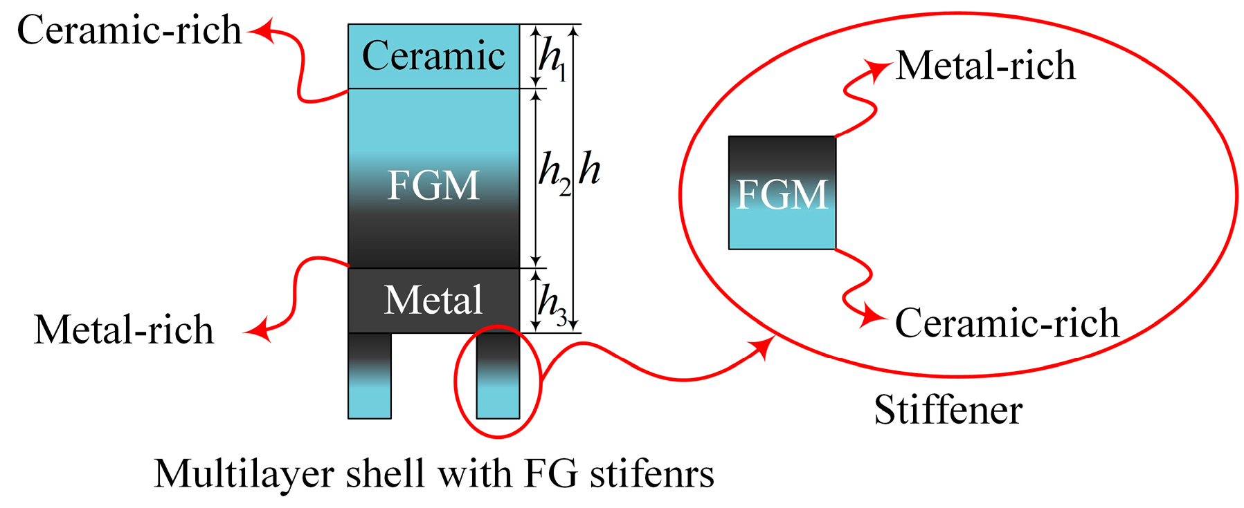
2.1. MFG Cylindrical Shells Reinforced by FGSSs

The configuration of the MFG cylindrical shells reinforced by FGSSs is illustrated in Figure 1. The dimensions of cylindrical shells, such as thickness ( h ), radius ( R ), and length ( L ), and the characteristics of the stiffeners, including width ( d ), angles ( θ , β ), thickness ( h s ), and spacing ( s ), are specified.
In the current research, the MFG cylindrical shells reinforced by FGSSs have three layers, which are revealed in Figure 2. The outermost layer of the shell is composed predominantly of ceramic, the innermost layer primarily of metal, and sandwiched between these is a layer of functionally graded material (FGM).
Volume fractions can be expressed based on the power law as below:
V c z = 2 z + h 2 2 H K ; H = h 2 , h s ; K = K s h , K s t V m z = 1 V c ( z )
where K 0 is the index of material power law. The designations s t , s h , m , and c represent the stiffeners, shell, metal, and ceramic. The material property ( P ) is a nonlinear function that varies with temperature:
P = P 0 P 1 T 1 + 1 + P 1 T + P 2 T 2 + P 3 T 3
The material properties, including Young’s modulus ( E ), thermal expansion ( α ), and mass density ( ρ ), according to the linear rule of mixture and the power law, are as follows:
Shell:
P s h z , T = P c T h 2 z h 2 + h 1 P c T + P m c T 2 z + h 2 h 1 2 h 2 K s h h 2 + h 1 z h 2 h 3 P m T h 2 h 3 z h 2
Internal stiffeners:
P s t z , T = P m T + P c m T 2 z + h 2 h s K s t          h 2 + h s z h 2
in which P = E , ρ , and α . Also, P m c = P m P c .

2.2. Governing Equation

In relation to the cylindrical shells’ middle plane strain components, they are articulated based on the nonlinear von Kármán strain–displacement equations [24] as outlined below:
ε x 0 ε y 0 γ x y 0 = u , x 0 0 0 v , y W / R v , x u , y 0 + w , x 2 / 2 w , y 2 / 2 w , x w , y
where w , v , and u are the displacements through the axes of x , y , z , respectively. Also, the normal strains ε x 0 and ε y 0 , along with the shear strain γ x y 0 , occur at the middle plane of the shell, while χ x y represents the twist and χ x and χ y denote the curvature changes. The strain components throughout the thickness of the shell at a distance z from the mid-surface are depicted as [25]
ε x ε y γ x y = ε x 0 ε y 0 γ x y 0 z χ x χ y 2 χ x y ;   χ x χ y χ x y = w , x x w , y y w , x y
Additionally, the cylindrical shell is required to fulfill the closed circumferential condition as specified below:
0 2 π R 0 L v , y d x d y = 0
Regarding Equation (4), the compatibility equation can be expressed as
ε x 0 , y y + ε y 0 , x x γ x y 0 , x y = w , x x / R + w , x y 2 w , x x w , y y
The relations for the stress–strain of MFG cylindrical shells [26] and FG spiral stiffeners are below:
  • MFG cylindrical shells:
σ x s h σ y s h τ x y s h = E s h z , T 1 ν 2 ν E s h z , T 1 ν 2 0 ν E s h z , T 1 ν 2 E s h z , T 1 ν 2 0 0 0 E s h z , T 2 1 + ν ε x ε y γ x y 1 + ν α T z 1 1 0
  • FG spiral stiffeners:
σ x s t σ y s t τ x y s t = H 1 cos 3 θ + cos 3 β H 2 sin 2 θ cos θ + sin 2 β cos β 2 H 3 sin θ cos 2 θ sin β cos 2 β H 1 sin θ cos 2 θ + sin β cos 2 β H 2 sin 3 θ + sin 3 β 2 H 3 sin 2 θ cos θ sin 2 β cos β H 1 cos 2 θ cos 2 β H 2 sin θ cos θ + sin β cos β 2 H 3 sin 2 θ sin 2 β ε x ε y γ x y
where
H 1 H 2 H 3 = d E s s sin γ sin θ + sin β cos θ + cos β 1 / 2 ;   γ = θ + β
In Equation (8a,b), ν is defined as Poisson’s ratio, while σ y s h ,   σ x s h and σ y s t , σ x s t represent the in-plane normal stresses for the shell and stiffeners, respectively, and τ x y s h and τ x y s t denote the corresponding shearing stresses. To obtain the steady-state heat conduction equation in a one-dimensional format, the temperature distribution across the thickness is assumed as below:
d d z K z d T d z = 0 ; h 2 z h 2
In Equation (10), K z is the thermal conductivity. Also, because of the large amount of R / h ratio, the influence of curvature is ignored. Equation (10) yields a polynomial series solution that describes the temperature distribution as below:
T z = T c + T m T c 2 z + h 2 h u 2 h m i = 0 2 z + h 2 h u 2 h m K s h K c m K m i i K s h + 1 i = 0 K c m K m i i K s h + 1
The approach of smeared stiffeners allows for the assumption that the impact of stiffeners on a cylindrical shell can be considered. It is presumed that thermal stress from the stiffeners is minimal and evenly spread across the entire structure of the shell, thereby allowing the thermal stress of the stiffeners to be disregarded [27]. The geometrical parameters of the stiffeners in a thermal environment are presented in [27]:
d T , s T , h s T = d , s , h s 1 + α s t z , T T z
In the analyses of MFG cylindrical shells reinforced by FGSS, we substitute d T , s T and h s T for d , s and h s . To calculate the resultant forces ( N x , N y , N x y ) and moments ( M x , M y , M x y ), we integrate the stress–strain Equation (8a,b) across the thickness, which is illustrated below:
N x N y N x y M x M y M x y = J 11 J 12 0 J 21 J 22 0 0 J 14 J 24 0 0 J 15 J 25 0 J 33 0 0 J 36 ε x 0 ε y 0 γ x y 0 J 14 J 15 0 J 24 J 25 0 0 J 41 J 51 0 0 J 42 J 52 0 J 36 0 0 J 63 χ x χ y 2 χ x y + ϕ 1 ϕ 1 0 ϕ 2 ϕ 2 0
where the stiffness components related to bending, extension, and coupling, denoted as J i j , are detailed in Appendix A.
The equilibrium equations for cylindrical shells based on the CST are as below [24,26]
N x , x + N x y , y = 0 N x y , x + N y , y = 0 M x , x x + 2 M x y , x y + M y , y y + N x w , x x + 2 N x y w , x y + N y w , y y + 1 R + Q t = ρ 1 w , t t + 2 ρ 1 c w , t
where c is the damping coefficient, and ρ 1 and the external excitation Q t are as below:
ρ 1 = ρ c T + ρ m c T K s h + 1 h 2 + 2 ρ m T + ρ c m T K s t + 1 d T h s T s T + ρ c T h 1 + ρ m T h 3 Q t = q ~ δ y y ~ cos Ω t
The first two equations of Equation (14) can be fulfilled simply through the designation of this stress function ( F ):
N x N y N x y = F , y y F , x x F , x y
By inserting Equation (13) into Equation (7) and the third part of Equation (14) and utilizing Equations (5) and (16), the equations of the system are derived as below:
J 11 * F , x x x x + J 33 * J 12 * + J 21 * F , x x y y + J 22 * F , y y y y + A 21 * w , x x x x + A 11 * + A 22 * 2 A 36 * w , x x y y + A 12 * w , y y y y + 1 R w , x x + w , x y 2 w , x x w , y y 2 w , x y + w , x x + w , y y = 0
ρ 1 w , t t + 2 ρ 1 c w , t + A 11 * * w , x x x x + A 12 * * + A 21 * * + 4 A 36 * * w , x x y y + A 22 * * w , y y y y A 21 * F , x x x x A 11 * + A 22 * 2 A 36 * F , x x y y A 12 * F , y y y y 1 R F , x x F , y y w , x x + 2 F , x y w , x y F , x x w , y y Q t = 0
where the coefficients A i j * ,   J i j *   a n d   A i j * * in Equation (17a,b) are presented in Appendix B.

2.3. Semi-Analytical Solutions

In this research, we give priority to the lower frequency modes over the higher frequency modes when examining the NVs of MFG cylindrical shells that are strengthened by FG spiral stiffeners and have simply supported boundaries [28,29]. It should be explained that the prioritization of lower frequency modes over higher frequency modes is due to their significant influence on the system’s overall dynamic response, especially in terms of transverse nonlinear oscillations. Lower frequency modes typically dominate the response of cylindrical shells under various loading conditions, providing fundamental insights into the shell’s behavior. The analysis concentrates on these modes in order to efficiently capture the most important features of nonlinear dynamic behavior, which are frequently connected with the most noticeable consequences in practical applications. Our study primarily investigates the system’s transverse nonlinear oscillations across the initial three modal orders. We opt for a mode function, expressed as w x , y , t = n = 1 M m = 1 M W t sin m π x ¯ sin n y ¯ , that adheres to the necessary boundary conditions. Here, x ¯ = x / L and y ¯ = y / R . Also, m represents the count of longitudinal modes, and n denotes the count of transversal modes. Consequently, we focus on the first three orders of vibration modes, assuming an approximate solution based on these parameters.
w x , y , t = W 1 t sin π x ¯ sin y ¯ + W 2 t sin π x ¯ sin 3 y ¯ + W 3 t sin 3 π x ¯ sin y ¯
Here, W 1 t , W 2 t , and W 3 t are, respectively, amplitudes of the first three order modes (i.e., ( m = 1 , n = 1 ), ( m = 1 , n = 3 ), and ( m = 3 , n = 1 )).
Equation (18) is substituted in Equation (17a) to seek the following biharmonic solution for F :
F = F 1 sin π x ¯ sin y ¯ + F 2 sin π x ¯ sin 3 y ¯ + F 3 sin 3 π x ¯ sin y ¯ + F 4 cos π x ¯ cos y ¯ cos 3 π x ¯ cos 3 y ¯ + F 5 sin π x ¯ sin y ¯ sin 3 π x ¯ sin 3 y ¯ + F 6 sin π x ¯ sin 3 π x ¯ sin 2 y ¯ + F 7 sin y ¯ sin 3 y ¯ sin 2 π x ¯ + F 8 cos y ¯ cos 3 y ¯ cos 2 π x ¯ + F 9 cos π x ¯ cos 3 π x ¯ cos 2 y ¯ + F 10 sin 2 π x ¯ sin 2 y ¯ + F 11 sin 6 π x ¯ sin 2 y ¯ + F 12 cos 2 π x ¯ cos 2 y ¯ + F 13 sin 2 π x ¯ sin 6 π x ¯ + F 14 cos 6 π x ¯ cos 2 y ¯ + F 15 cos 2 π x ¯ cos 6 y ¯ + F 16 sin π x ¯ sin 3 π x ¯ + F 17 sin y ¯ sin 3 y ¯ + F 18 cos y ¯ cos 3 y ¯ + F 19 cos π x ¯ cos 3 π x ¯ + F 20 cos 2 π x ¯ + F 21 cos 2 y ¯ + F 22 sin 2 π x ¯ + F 23 sin 2 y ¯ + F 24 sin 6 π x ¯ + F 25 cos 6 y ¯ + F 26 cos 6 π x ¯ + N y 0 x 2 / 2
in which F i j depends on variables such as π , R , L , J i j * , A i j * , A i j * * , and W i   i = 1 , 2 , 3 . While the formulas for these coefficients are too long to be written here explicitly, they are readily computable using computer algebra software (Maple 2016). By substituting Equations (18) and (19) into Equation (6), N y 0 is derived as below:
N y 0 = W 1 t + 9 W 2 t + W 3 t 8 R 2 I 22 * I 12 * I 22 * I 22 * ϕ 1
Using the Galerkin approach, and substituting Equations (22)–(24) into Equation (17b), the discretized motion equations are obtained as below:
W ¨ 1 + 2 c W ˙ 1 + ω 1 2 W 1 + h 11 W 1 3 + h 12 W 1 2 W 2 + h 13 W 1 2 W 3 + h 14 W 1 W 2 2 + h 15 W 1 W 2 W 3 + h 16 W 1 W 3 2 + h 17 W 2 2 W 3 + h 18 W 2 W 3 2 + h 19 W 3 3 + h 110 W 1 W 2 + h 111 W 1 W 3 = q 1 cos Ω t W ¨ 2 + 2 c W ˙ 2 + ω 2 2 W 2 + h 21 W 1 3 + h 22 W 1 2 W 2 + h 23 W 1 2 W 3 + h 24 W 1 W 2 W 3 + h 25 W 1 W 3 2 + h 26 W 2 3 + h 27 W 2 2 W 3 + h 28 W 1 2 + h 29 W 1 W 3 = q 2 cos Ω t W ¨ 3 + 2 c W ˙ 3 + ω 3 2 W 3 + h 31 W 1 3 + h 32 W 1 2 W 2 + h 33 W 1 2 W 3 + h 34 W 1 W 2 2 + h 35 W 1 W 2 W 3 + h 36 W 1 W 3 2 + h 37 W 2 2 W 3 + h 38 W 3 3 + h 39 W 1 2 + h 310 W 1 W 2 = q 3 cos Ω t
in which the coefficients h i j , q i , and ω i i = 1 , 2 , 3 depend on variables such as π , R , L , J i j * , A i j * , A i j * * , ρ 1 , and T . Similarly, while the formulas for these coefficients are too long to be written here explicitly, they are readily computable using computer algebra software.

2.4. Addressing the Nonlinear Equation with the MMSs

To solve Equation (21) via the MMSs, an expansion is adopted as below:
W j t , ϵ = W j 0 T 0 , T 1 + ϵ W j 1 T 0 , T 1 +
For j = 1 , 2 , 3 , we define new variables dependent on time, T 0 and T 1 , where each T n is expressed as ϵ n t for n = 0,1 . This formulation necessitates the use of differential operators, with the first derivative represented as d / d t = D 0 + ϵ D 1 + and the second derivative as d 2 / d t 2 = D 0 2 + 2 ϵ D 0 D 1 + , where D i = / T i i = 1 , 2 . This research explores the case where there are 1:2:4 internal resonance and subharmonic resonance of order 1/2, leading to the following resonant relationships:
Ω = 2 ω 1 + ϵ σ 1 ; ω 2 = 2 ω 1 + ϵ σ 2 ; ω 3 = 4 ω 1 + ϵ σ 3
where σ i i = 1 , 2 , 3 represents detuning parameters.
Substitution of Equations (22) and (23) in Equation (21), followed by setting the coefficients of the perturbation terms ϵ 0 and ϵ to zero, results in
Order ϵ 0 :
D 0 2 W i 0 + 4 i 1 ω 1 2 W i 0 = 0 ; i = 1 , 2 , 3
Order ϵ :
D 0 2 W i 1 + 4 i 1 ω 1 2 W i 1 = 2 D 0 D 1 W i 0 2 μ D 0 W i 0 2 i σ i W i 0 g i 1 W 10 3 g i 2 W 10 2 W 20 g i 3 W 10 2 W 30 j g i 4 W 10 W 20 2 g i 5 W 10 W 20 W 30 g i 6 W 10 W 30 2 g i 7 W 20 2 W 30 k g i 8 W 20 W 30 2 l g i 9 W 30 3 q g i 10 W 20 3 n g i 11 W 10 3 m g i 12 W 10 W 20 p g i 13 W 10 W 30 + f i cos Ω t ;   i = 1 , 2 , 3
Here, i = 1 n = 0 , q = 0 ; i = 2 j = 0 , l = 0 , k = 0 , m = 0 ; i = 3 k = 0 , q = 0 ; p = 0 .
The general solution of Equation (24) is
W j 0 = A j T 1 e 2 j 1 i ω 1 T 0 + A ¯ j T 1 e 2 j 1 i ω 1 T 0 ;   j = 1 , 2 , 3
Substituting Equation (26) in Equation (25), yields:
D 0 2 W 11 + W 11 = ( 2 ω 1 D 1 A 1 i + 2 ω 1 μ A 1 i + 2 σ 1 A 1 + 3 g 11 A 1 2 A ¯ 1 + 2 g 14 A 2 A ¯ 2 A 1 + 2 g 16 A 3 A ¯ 3 A 1 + g 15 A 3 A ¯ 2 A ¯ 1 + 3 g 19 A 1 2 A ¯ 1 + g 110 A 2 A ¯ 1 ) e i ω 1 T 0 + c . c . + N S T D 0 2 W 21 + W 21 = ( 4 ω 1 D 1 A 2 i + 4 ω 1 μ A 2 i + 4 σ 2 A 2 + 3 g 26 A 2 2 A ¯ 2 + 2 g 22 A 1 A ¯ 1 A 2 + 2 g 27 A 3 A ¯ 3 A 2 + g 23 A ¯ 1 2 A 3 + g 28 A 1 2 1 2 f 2 ) e 2 ω 1 i T 0 + c . c . + N S T D 0 2 W 31 + W 31 = ( 8 ω 1 D 1 A 3 i + 8 ω 1 μ A 3 i + 8 σ 3 A 3 + 3 g 38 A 3 2 A ¯ 3 + 2 g 37 A 2 A ¯ 2 A 3 + 2 g 33 A 1 A ¯ 1 A 3 + g 32 A 1 2 A 2 ) e 4 ω 1 i T 0 + c . c . + N S T
Here, N S T and c . c . denote the non-secular terms and the complex conjugate, respectively. In Equation (27), setting the secular terms to zero results in deriving the following complex equations.
D 1 A 1 = μ A 1 + 1 ω 1 ( σ 1 A 1 + 3 2 g 11 A 1 2 A ¯ 1 + g 14 A 2 A ¯ 2 A 1 + g 16 A 3 A ¯ 3 A 1 + 1 2 g 15 A 3 A ¯ 2 A ¯ 1 + 3 2 g 19 A 1 2 A ¯ 1 + 1 2 g 110 A 2 A ¯ 1 ) i D 1 A 2 = μ A 2 + 1 ω 1 ( σ 2 A 2 + 3 4 g 26 A 2 2 A ¯ 2 + 1 2 g 22 A 1 A ¯ 1 A 2 + 1 2 g 27 A 3 A ¯ 3 A 2 + 1 4 g 23 A ¯ 1 2 A 3 + 1 4 g 28 A 1 2 + 1 2 f 2 ) i D 1 A 3 = μ A 3 + 1 ω 1 σ 3 A 3 + 3 8 g 38 A 3 2 A ¯ 3 + 1 4 g 37 A 2 A ¯ 2 A 3 + 1 4 g 33 A 1 A ¯ 1 A 3 + 1 8 g 32 A 1 2 A 2 i
To find the response of Equation (28), A i i = 1 , 2 , 3 is assumed as below:
A j = x 2 j 1 + i x 2 j ;   j = 1 , 2 , 3
In Equation (29), x i i = 1 , 2 , , 6 is defined as variables corresponding to the amplitude and phase of the NVs of MFG cylindrical shells reinforced by FGSSs. After substitution of Equation (29) into Equation (28), the imaginary and real parts of the resultant equation are
x ˙ 1 = μ x 1 + 1 ω 1 ( σ 1 x 2 3 2 g 19 x 2 3 3 2 g 11 x 2 3 g 14 x 3 2 x 2 g 14 x 4 2 x 2 g 16 x 5 2 x 2 g 16 x 6 2 x 2 3 2 g 11 x 1 2 x 2 3 2 g 19 x 1 2 x 2 + 1 2 g 15 x 2 x 4 x 6 + 1 2 g 15 x 1 x 4 x 5 + 1 2 g 15 x 2 x 3 x 5 1 2 g 15 x 1 x 3 x 6 1 2 g 110 x 1 x 4 + 1 2 g 110 x 2 x 3 ) x ˙ 2 = μ x 2 + 1 ω 1 ( σ 1 x 1 + 3 2 g 19 x 1 3 + 3 2 g 11 x 1 3 + g 14 x 3 2 x 1 + g 14 x 4 2 x 1 + g 16 x 5 2 x 1 + g 16 x 6 2 x 1 + 3 2 g 11 x 2 2 x 1 + 3 2 g 19 x 2 2 x 1 + 1 2 g 15 x 1 x 4 x 6 + 1 2 g 15 x 1 x 3 x 5 + 1 2 g 15 x 2 x 3 x 6 1 2 g 15 x 2 x 4 x 6 + 1 2 g 110 x 1 x 3 + 1 2 g 110 x 2 x 4 ) x ˙ 3 = μ x 3 + 1 ω 1 ( σ 2 x 4 3 4 g 26 x 4 3 1 2 g 22 x 2 2 x 4 1 2 g 22 x 1 2 x 4 1 2 g 27 x 5 2 x 4 1 2 g 27 x 6 2 x 4 3 4 g 26 x 3 2 x 4 1 4 g 23 x 1 2 x 6 + 1 4 g 23 x 2 2 x 6 + 1 2 g 23 x 1 x 2 x 5 1 2 g 28 x 1 x 2 ) x ˙ 4 = μ x 4 + 1 ω 1 ( σ 2 x 3 + 3 4 g 26 x 3 3 + 1 2 g 22 x 2 2 x 3 + 1 2 g 22 x 1 2 x 3 + 1 2 g 27 x 5 2 x 3 + 1 2 g 27 x 6 2 x 3 + 3 4 g 26 x 4 2 x 3 + 1 4 g 23 x 1 2 x 5 1 4 g 23 x 2 2 x 5 + 1 2 g 23 x 1 x 2 x 6 + 1 4 g 28 x 1 2 1 4 g 28 x 2 2 ) x ˙ 5 = μ x 5 + 1 ω 1 ( σ 3 x 6 3 8 g 38 x 6 3 3 8 g 38 x 5 2 x 6 1 4 g 33 x 2 2 x 6 1 4 g 33 x 1 2 x 6 1 4 g 37 x 3 2 x 6 1 4 g 37 x 4 2 x 6 1 8 g 32 x 1 2 x 4 + 1 8 g 32 x 2 2 x 4 1 4 g 32 x 1 x 2 x 3 ) x ˙ 6 = μ x 6 + 1 ω 1 ( σ 3 x 5 + 3 8 g 38 x 5 3 + 3 8 g 38 x 6 2 x 5 + 1 4 g 33 x 2 2 x 5 + 1 4 g 33 x 1 2 x 5 + 1 4 g 37 x 3 2 x 5 + 1 4 g 37 x 4 2 x 5 + 1 8 g 32 x 1 2 x 3 1 8 g 32 x 2 2 x 3 1 4 g 32 x 1 x 2 x 4 )

3. Numerical Results

3.1. Validation of the Current Results

In our computational analysis, the first step is to confirm the accuracy of the results for specific circumstances by comparing them to recent study findings. Table 1 shows that the dimensionless natural frequencies (NFs) produced in our investigation have been cross-validated with data given by Zhang et al. [30], Song et al. [31], and Yang et al. [32]. These validations reveal strong agreement with the linked studies. These references provide the relation of dimensionless NFs in the following form:
ω ¯ n = ω n R 1 ν 2 ρ E

3.2. Results of NVs for MFG Cylindrical Shells Reinforced by FGSS

Here, the NVs of the MFG cylindrical shells reinforced by FGSSs are examined. In this regard, MATLAB software (MATLAB 2019a) is used to solve the equations presented in this research. The system is made up of S i 3 N 4 , a ceramic material, and S U S 304 , a type of metal. The properties of these materials are detailed in Table 2. Additionally, the structural dimensions of the system are provided in Table 3, which are required for deriving the outcomes.
Figure 3 illustrates the first three mode shapes of MFG cylindrical shells reinforced by FGSSs, represented in three dimensions (3D). It is important to highlight that all the numerical results in this research are derived from the analysis of these three modes.
The impact of the damping coefficient on the waveforms and the phase diagrams of the NVs of MFG cylindrical shells reinforced by FGSSs, featuring subharmonics of order 1/2 and 1:2:4 internal resonances, is depicted in Figure 4. The vibration amplitude of the system, considering the first three order modes, is decreased. As can be seen, the velocity for the modes ( m = 3 , n = 1 ) is lower than for others. Also, the maximum deflection versus velocity curve of the MFG cylindrical shells reinforced by FGSS with the modes ( m = 1 , n = 1 ) becomes more disordered.
The influence of symmetric or asymmetric angles of stiffeners on the waveforms and phase diagrams of NVs in MFG cylindrical shells reinforced by FGSSs, featuring subharmonic orders of 1/2 and internal resonances of 1:2:4, is illustrated in Figure 5, Figure 6, Figure 7, Figure 8, Figure 9, Figure 10, Figure 11, Figure 12, Figure 13 and Figure 14. According to these figures, the maximum deflection versus velocity curve of the MFG cylindrical shells reinforced by FGSSs for modes ( m = 1 , n = 1 ) and ( m = 3 , n = 1 ) becomes more disorderly with the stiffener’s angle θ = β = 0 ° or θ = β = 90 ° . On the contrary, for modes ( m = 1 , n = 3 ), the curves become less disorderly when the stiffener angle θ = β = 0 ° or θ = β = 90 ° . Notably, the vibration amplitude and velocity of the system with the first three-order modes are highest at the stiffener angle θ = β = 0 ° . Furthermore, the vibration amplitude of shells for modes ( m = 1 , n = 1 ) with stiffener angles θ = β = 60 ° or θ = 60 ° and β = 90 ° , as well as those for modes ( m = 1 , n = 3 ) with stiffener angles θ = 60 ° and β = 90 ° , is lower than others. Shells with modes ( m = 3 , n = 1 ) exhibit this trend at stiffener angles θ = 0 ° and β = 30 ° or θ = 0 ° and β = 90 ° or θ = 30 ° and β = 90 ° . Conversely, the velocity is lower for modes ( m = 1 , n = 1 ) at θ = 30 ° and β = 60 ° , for modes ( m = 1 , n = 3 ) at β = 90 ° and θ = 0 ° or θ = 60 ° , and for modes ( m = 3 , n = 1 ) at θ = 30 ° and β = 30 ° or β = 60 ° or θ = β = 60 ° . The phase plane of the vibration of MFG cylindrical shells reinforced by FGSSs for modes (m = 3, n = 1) with stiffener angles θ = 0 ° and β = 60 ° quickly trends towards a limit cycle, thereby rapidly stabilizing the NVs of the system.
Figure 15 illustrates the impact of temperature on the NVs of MFG cylindrical shells reinforced by FGSSs, featuring subharmonic orders of 1/2 and internal resonances of 1:2:4. As shown in this figure, increasing the temperature increases the disorder in the maximum deflection versus velocity curve of the MFG cylindrical shells reinforced by FGSSs for the modes ( m = 1 ,   n = 1 ) and ( m = 3 ,   n = 1 ). However, an increase in temperature slightly decreases the vibration amplitude for the modes ( m = 1 ,   n = 1 ).

4. Conclusions

A semi-analytical approach was utilized to examine the NVs of MFG cylindrical shells reinforced by FGSSs under a thermal condition. The cylindrical shell has three layers: an outer ceramic-rich layer, a middle FG layer, and an inner metal-rich layer. Nonlinear vibrations were addressed using the von Kármán equations, smeared stiffeners, and the Galerkin method. To discover resonances, the MMSs was used, with a focus on the 1:2:4 internal resonance and a sub-harmonic resonance of order 1/2. This research also investigates how differences in material composition, geometric configurations, ambient temperature, and the stiffeners’ angular symmetry or asymmetry affect the vibrational response of these reinforced shells. The key findings are summarized as follows:
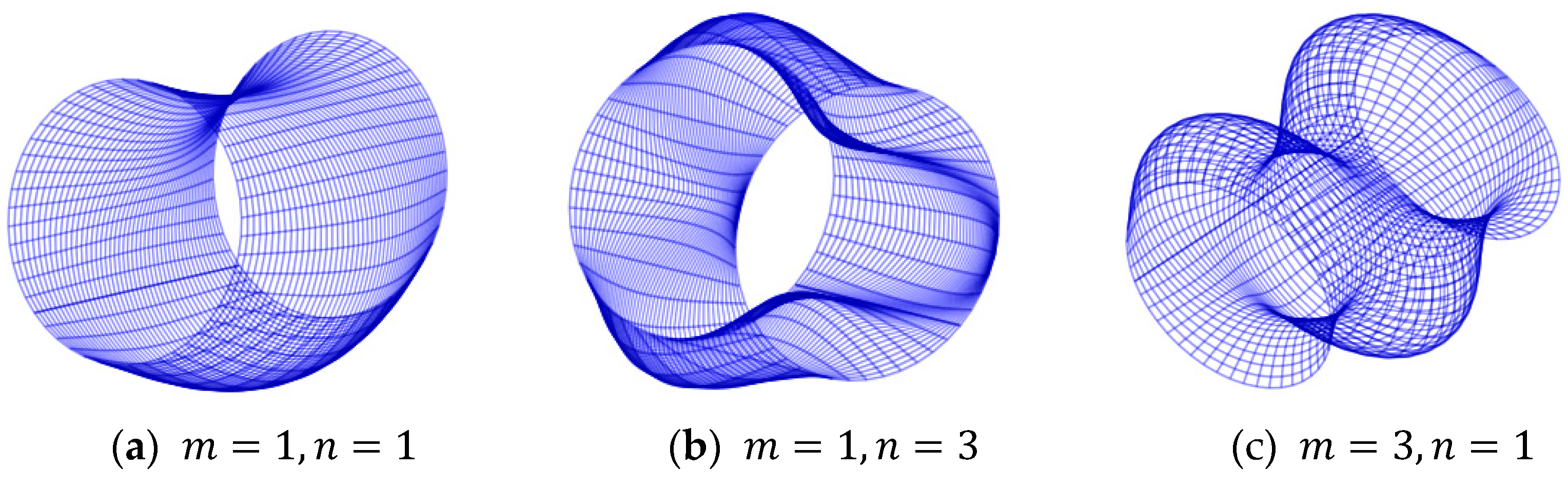
  • The velocity of MFG cylindrical shells reinforced by FGSSs is lower in the modes ( m = 1 , n = 1 ) with stiffener angles θ = 30 ° and β = 60 ° , in the modes ( m = 1 , n = 3 ) with stiffener angles β = 90 ° and θ = 0 ° or θ = 60 ° , and in the modes ( m = 3 , n = 1 ) with stiffener angles θ = 30 ° and β = 30 ° or β = 60 ° or θ = β = 60 ° , compared to other configurations.
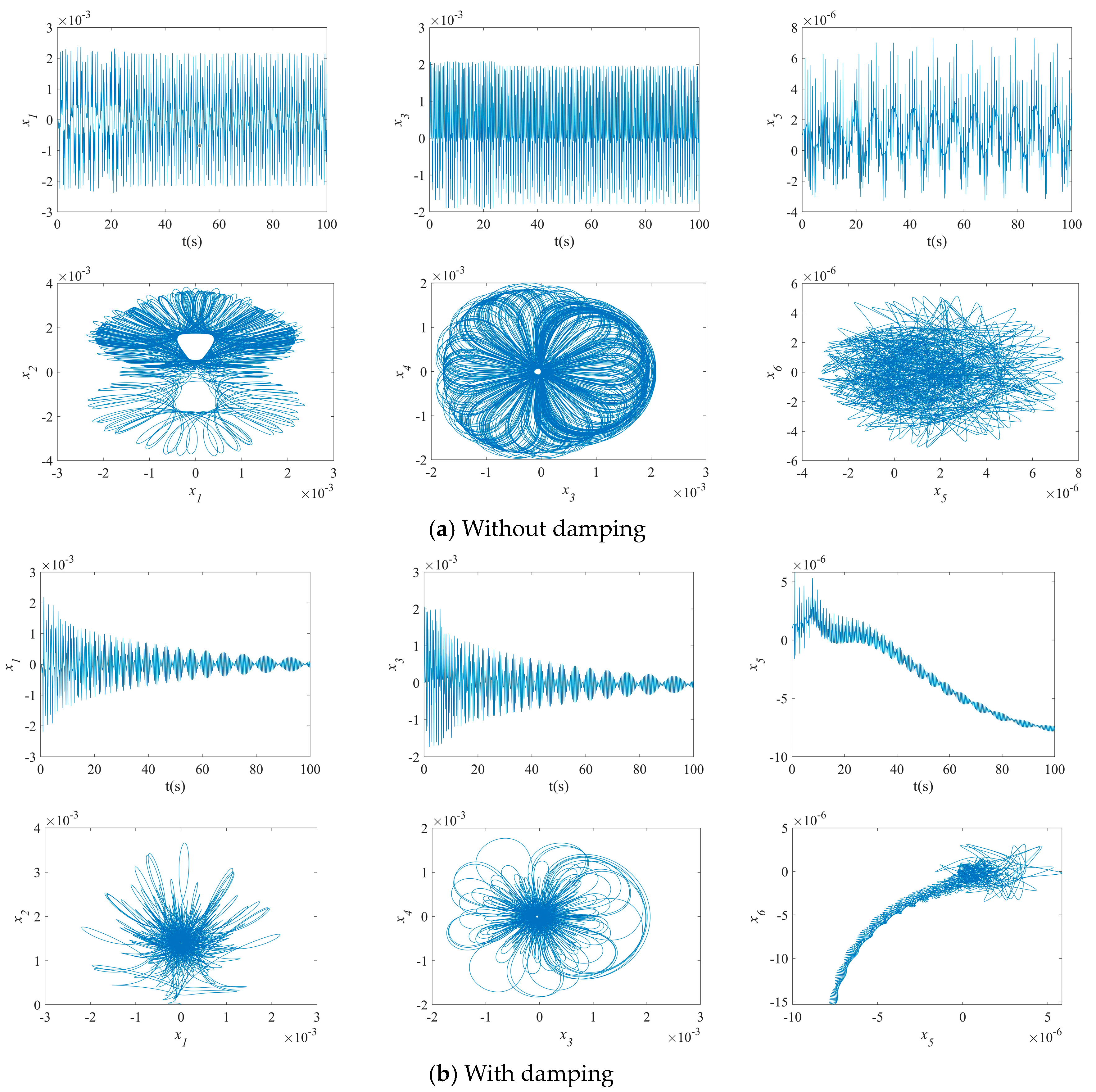
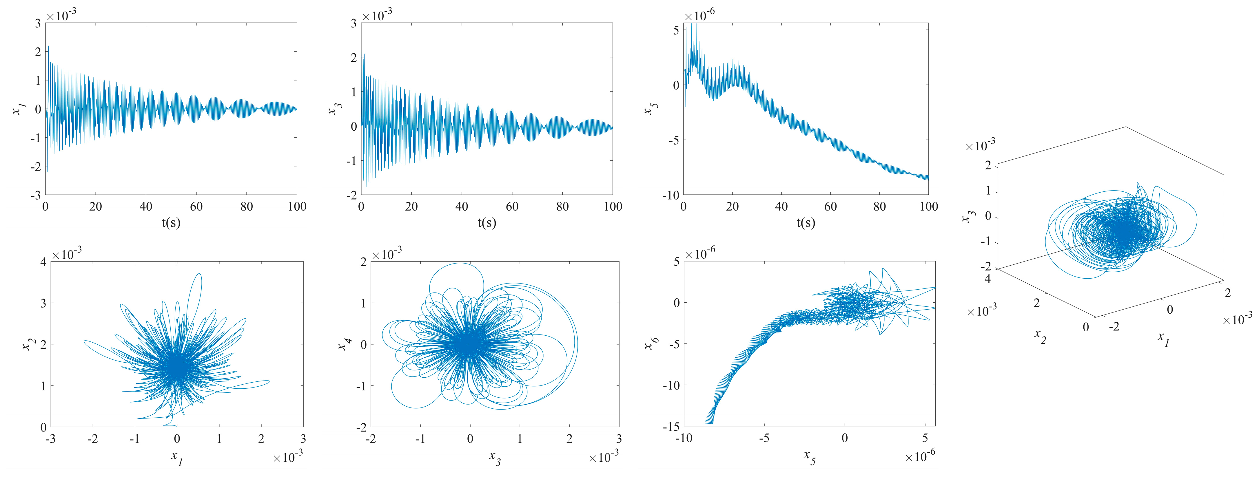
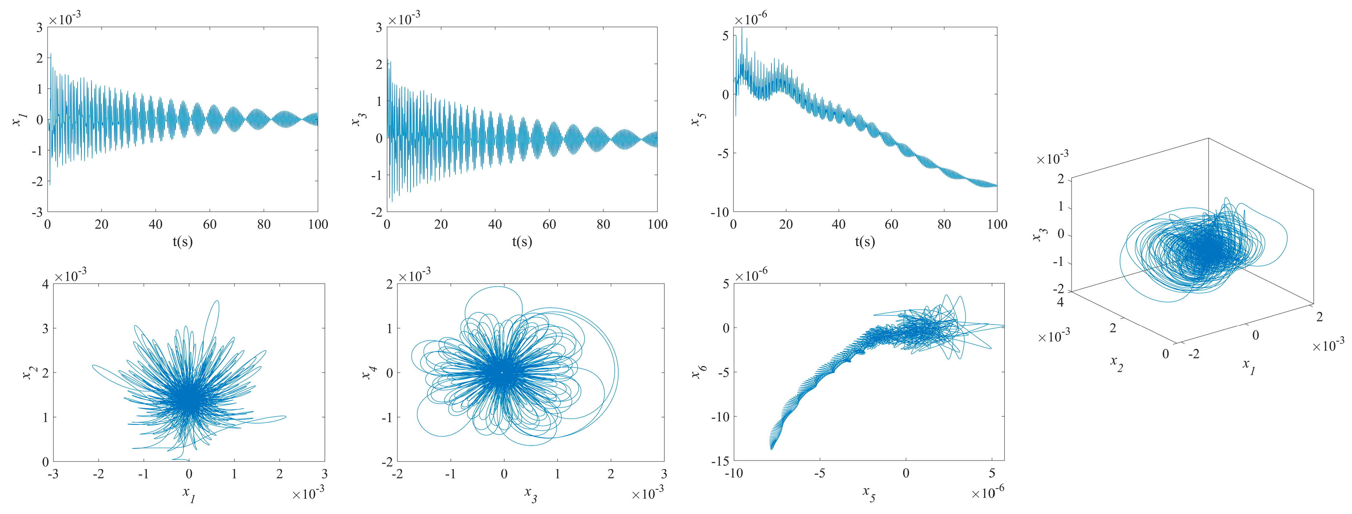
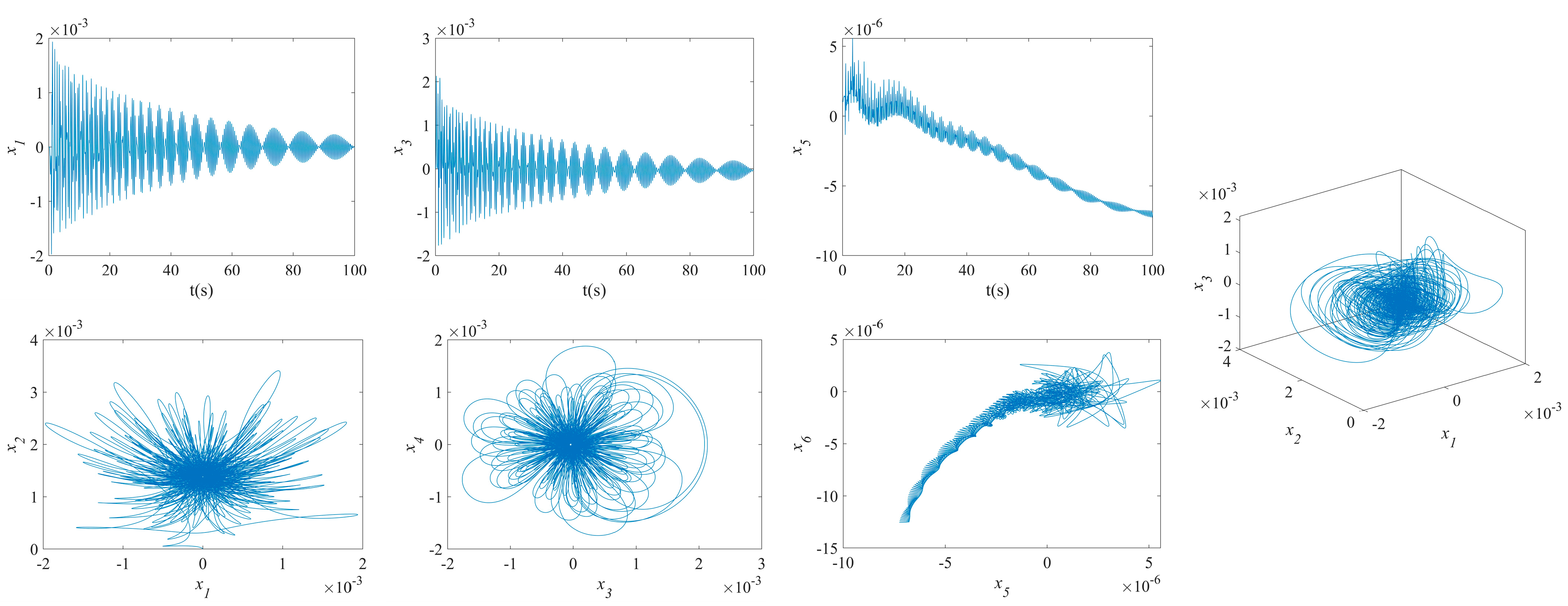
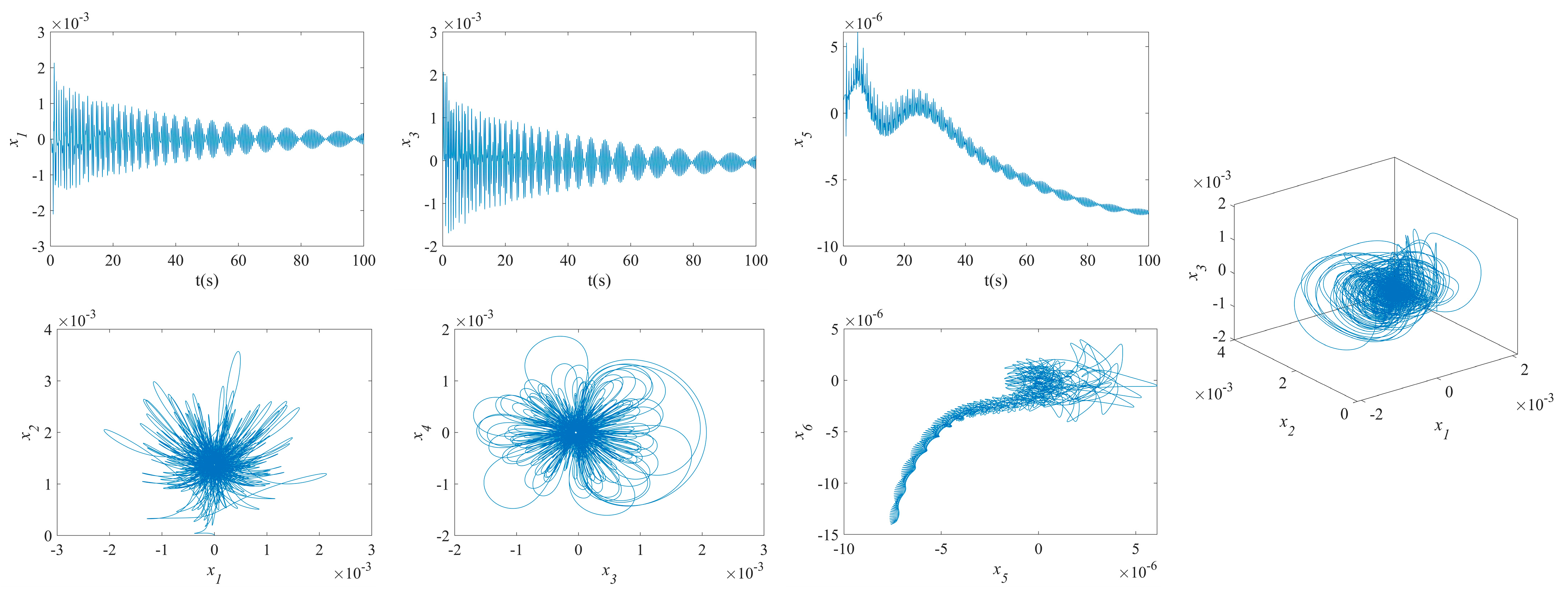
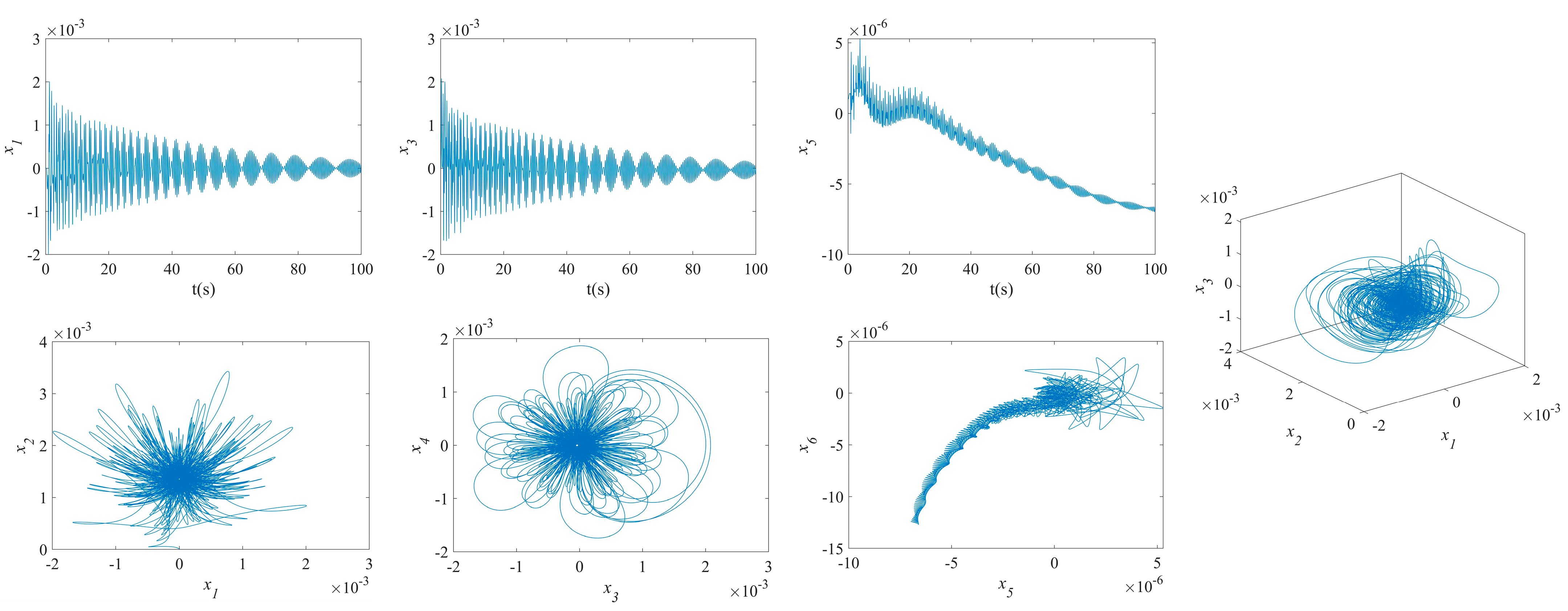
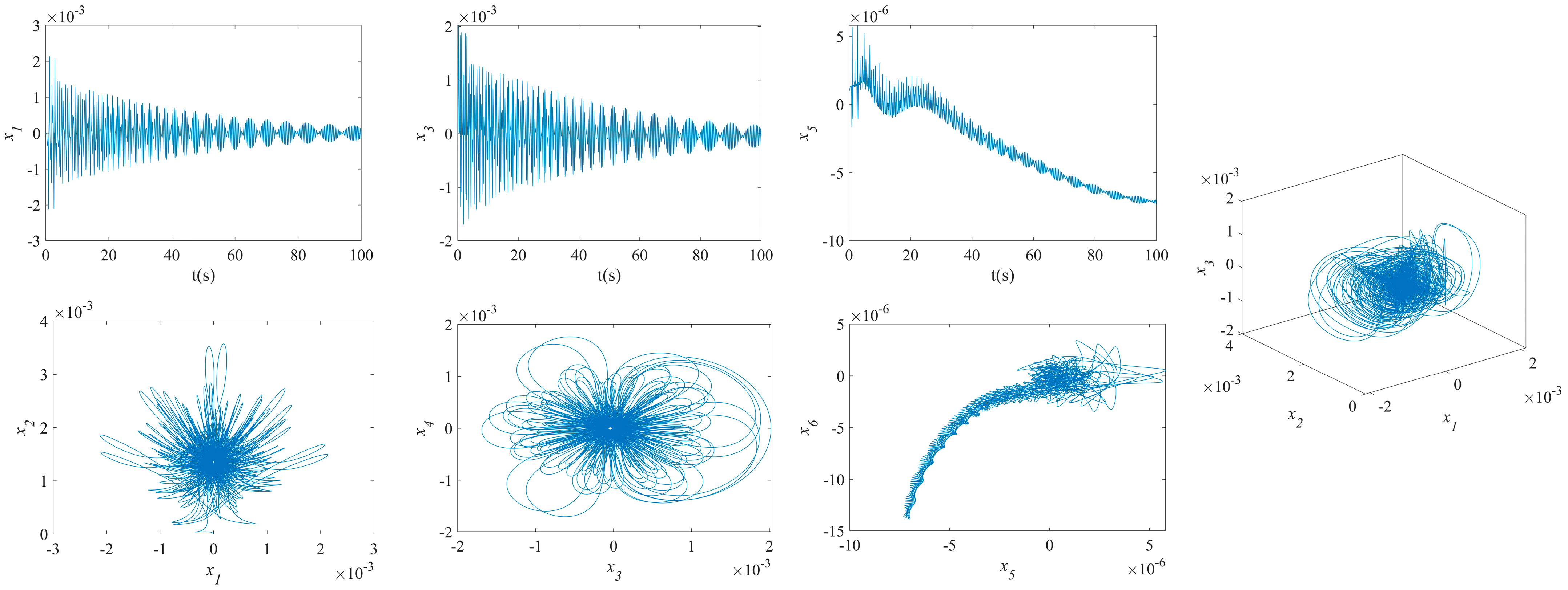
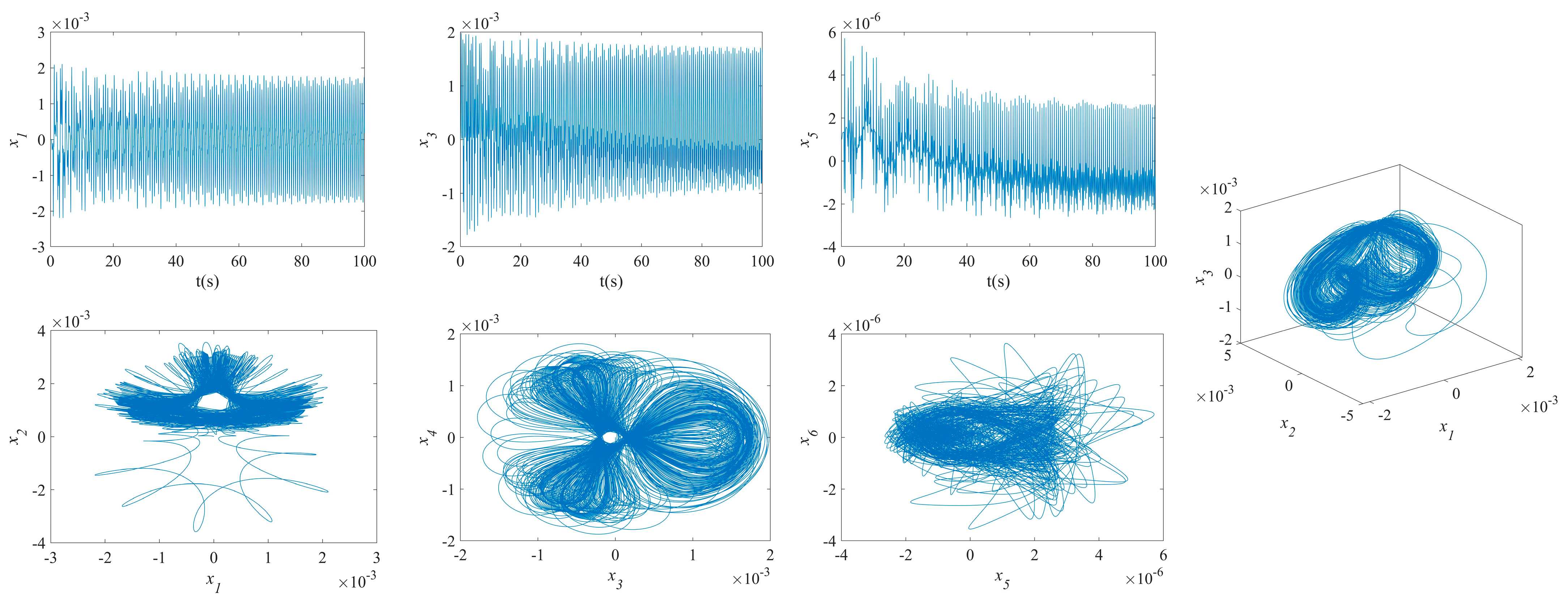
  • The phase plane of the vibration of the MFG cylindrical shells, reinforced by FGSSs with modes ( m = 3 , n = 1 ) and stiffener angles θ = 0 ° and β = 60 ° , tends towards a limit cycle quickly. Consequently, the NVs of the system are stabilized rapidly.
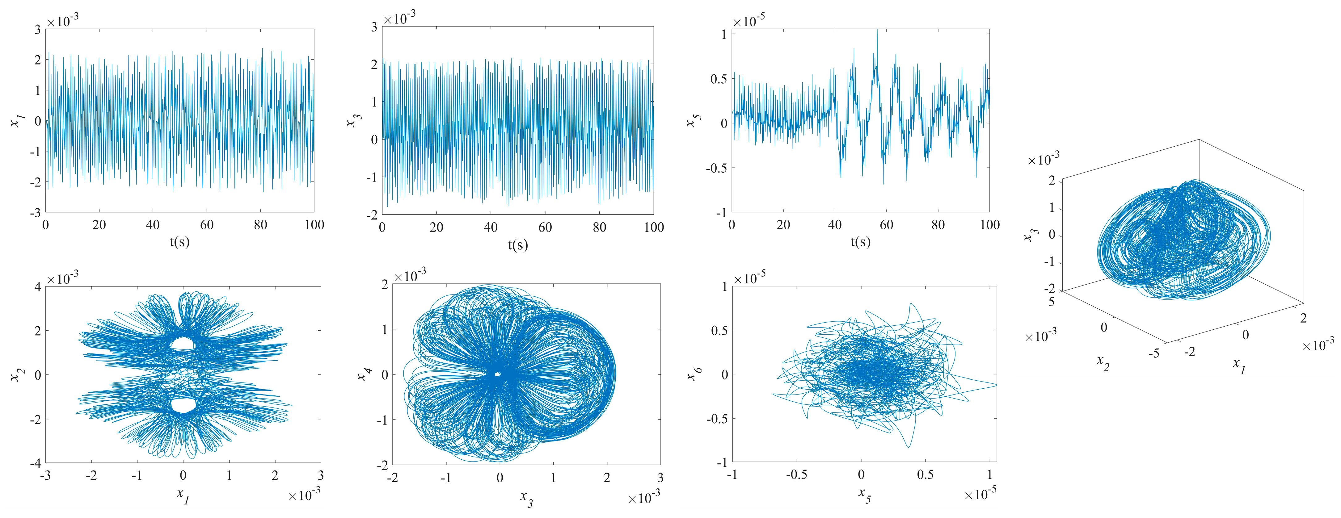
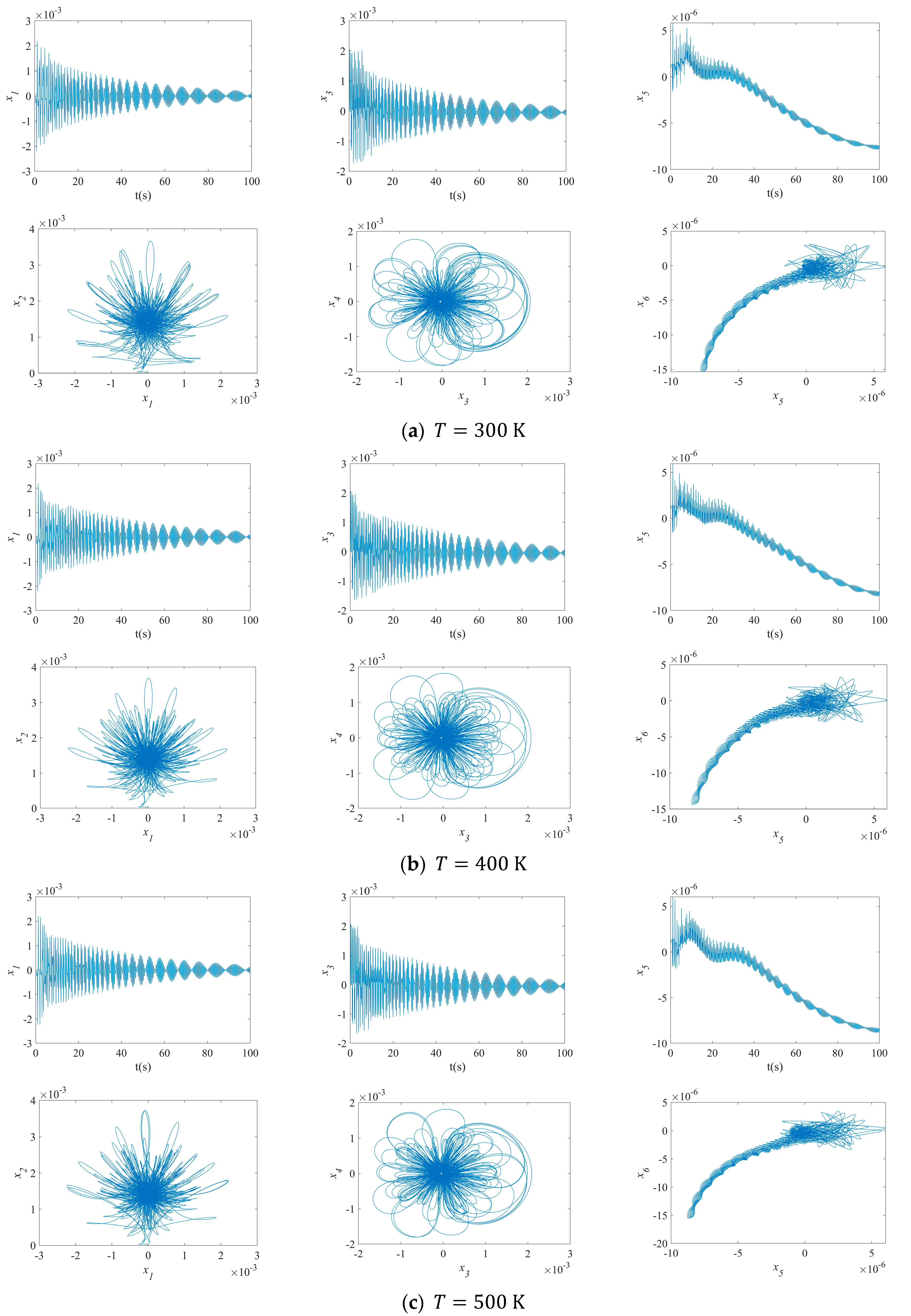
  • By increasing the temperatures, the disorder on the maximum deflection versus velocity curve of the MFG cylindrical shells reinforced by FGSSs with the modes ( m = 1 ,   n = 1 ) and the modes ( m = 3 ,   n = 1 ) increases. Conversely, the vibration amplitude of the system with the modes ( m = 1 ,   n = 1 ) decreases slightly.
This study makes important advances in the field of MFG cylindrical shells reinforced by FGSS, which can be used directly in a variety of industries including aerospace, marine, and civil engineering. The ability of these shells to withstand and adapt to different thermal environments makes them ideal for aerospace industry applications, where enhanced vibrational characteristics can improve the durability and performance of aircraft components that are frequently subjected to extreme thermal variations and mechanical vibrations. Marine engineering applications in submarine and ship hull designs can benefit from better resilience to harsh maritime environmental conditions, lowering maintenance costs, and increasing vessel lifespan. Furthermore, civil engineering infrastructure components such as bridges and buildings can benefit from the improved mechanical characteristics of these shells to better withstand natural disasters and environmental stressors, hence increasing safety and reliability.

Author Contributions

Conceptualization, K.F. and F.T.; methodology, K.F.; software, K.F.; validation, K.F. and F.T.; formal analysis, K.F.; investigation, K.F.; resources, K.F.; data curation, K.F. and F.T.; writing—original draft preparation, K.F.; writing—review and editing, F.T.; visualization, K.F.; supervision, F.T. project administration, F.T.; funding acquisition, F.T. All authors have read and agreed to the published version of the manuscript.

Funding

This research is partially supported by the Natural Sciences and Engineering Research Council of Canada (NSERC-DG Grant No.: RGPIN-2024-06363), awarded to Dr. Farshid Torabi.

Data Availability Statement

Data are contained within the present article.

Conflicts of Interest

The authors declare no conflicts of interest.

Appendix A

J 11 = E 1 1 ν 2 + Z 1 E 1 s cos 3 θ + cos 3 β ,   J 12 = E 1 ν 1 ν 2 + Z 1 E 1 s sin 2 θ cos θ + sin 2 β cos β J 14 = E 2 1 ν 2 + Z 1 E 2 s cos 3 θ + cos 3 β ,   J 15 = E 2 ν 1 ν 2 + Z 1 E 2 s sin 2 θ cos θ + sin 2 β cos β J 21 = E 1 ν 1 ν 2 + Z 2 E 1 s sin θ cos 2 θ + sin β cos 2 β ,   J 22 = E 1 1 ν 2 + Z 2 E 1 s sin 3 θ + sin 3 β J 24 = E 2 ν 1 ν 2 + Z 2 E 2 s sin θ cos 2 θ + sin β cos 2 β ,   J 25 = E 2 1 ν 2 + Z 2 E 2 s sin 3 θ + sin 3 β J 41 = E 3 1 ν 2 + Z 1 E 3 s cos 3 θ + cos 3 β ,   J 42 = E 3 ν 1 ν 2 + Z 1 E 3 s sin 2 θ cos θ + sin 2 β cos β J 51 = E 3 ν 1 ν 2 + Z 2 E 3 s sin θ cos 2 θ + sin β cos 2 β ,   J 55 = E 3 1 ν 2 + Z 2 E 3 s sin 3 θ + sin 3 β J 33 = E 1 2 1 + ν + 2 Z 3 E 1 s sin θ cos θ + sin β cos β J 36 = E 2 2 1 + ν + 2 Z 3 E 2 s sin θ cos θ + sin β cos β J 36 = E 3 2 1 + ν + 2 Z 3 E 3 s sin θ cos θ + sin β cos β

Appendix B

Δ = J 11 J 22 J 12 J 21 ,   J 22 * = J 22 Δ , J 12 * = J 12 Δ , J 11 * = J 11 Δ ,   J 21 * = J 21 Δ , J 33 * = 1 J 33 , J 36 * = J 36 J 33 A 11 * = J 22 * J 14 J 21 * J 15 , A 21 * = J 11 * J 15 J 12 * J 14 , A 12 * = J 22 * J 24 J 21 * J 25 , A 22 * = J 11 * J 25 J 12 * J 24 A 11 * * = J 11 * * J 14 J 21 * * J 15 J 41 , A 12 * * = J 12 * * J 14 J 22 * * J 15 J 42 , A 21 * * = J 11 * * J 24 J 21 * * J 25 J 51 A 22 * * = J 12 * * J 24 J 22 * * J 25 J 52 , A 36 * * = J 36 * * J 36 J 63

References

  1. Zhang, Y.; Zhang, W.; Yao, Z. Analysis on nonlinear vibrations near internal resonances of a composite laminated piezoelectric rectangular plate. Eng. Struct. 2018, 173, 89–106. [Google Scholar] [CrossRef]
  2. Wang, Y.; Yang, Z. Nonlinear vibrations of moving functionally graded plates containing porosities and contacting with liquid: Internal resonance. Nonlinear Dynam. 2017, 90, 1461–1480. [Google Scholar] [CrossRef]
  3. Permoon, M.; Haddadpour, H.; Javadi, M. Nonlinear vibration of fractional viscoelastic plate: Primary, subharmonic, and superharmonic response. Int. J. Nonlinear Mech. 2018, 99, 154–164. [Google Scholar] [CrossRef]
  4. Ansari, R.; Gholami, R. Nonlinear primary resonance of third-order shear deformable functionally graded nanocomposite rectangular plates reinforced by carbon nanotubes. Compos. Struct. 2016, 54, 707–723. [Google Scholar] [CrossRef]
  5. Wang, Y. Electro-mechanical vibration analysis of functionally graded piezoelectric porous plates in the translation state. Acta. Astronaut. 2018, 143, 263–271. [Google Scholar] [CrossRef]
  6. Mahmoudkhani, S.; Navazi, H.M.; Haddadpour, H. An analytical study of the non-linear vibrations of cylindrical shells. Int. J. Nonlinear Mech. 2011, 46, 1361–1372. [Google Scholar] [CrossRef]
  7. Rodrigues, L.; Gonçalves, P.B.; Silva, F.M.A. Internal resonances in a transversally excited imperfect circular cylindrical shell. Pro. Eng. 2017, 199, 838–843. [Google Scholar] [CrossRef]
  8. Wang, Y.; Liang, L.; Guo, X. Internal resonance of axially moving laminated circular cylindrical shells. J. Sound Vib. 2013, 332, 6434–6450. [Google Scholar] [CrossRef]
  9. Zhang, W.; Liu, T.; Xi, A.; Wang, Y. Resonant responses and chaotic dynamics of composite laminated circular cylindrical shell with membranes. J. Sound Vib. 2018, 423, 65–99. [Google Scholar] [CrossRef]
  10. Abe, A.; Kobayashi, Y.; Yamada, G. Nonlinear dynamic behaviors of clamped laminated shallow shells with one-to-one internal resonance. J. Sound Vib. 2007, 304, 957–968. [Google Scholar] [CrossRef]
  11. Li, F.; Yao, G. 1/3 Subharmonic resonance of a nonlinear composite laminated cylindrical shell in subsonic air flow. Compos. Struct. 2013, 100, 249–256. [Google Scholar] [CrossRef]
  12. Li, X. Parametric resonances of rotating composite laminated nonlinear cylindrical shells under periodic axial loads and hygrothermal environment. Compos. Struct. 2021, 255, 112887. [Google Scholar] [CrossRef]
  13. Sofiyev, A.H. Large amplitude vibration of FGM orthotropic cylindrical shells interacting with the nonlinear Winkler elastic foundation. Compos. Part B Eng. 2016, 98, 141–150. [Google Scholar] [CrossRef]
  14. Sofiyev, A.H.; Hui, D.; Haciyev, V.C.; Erdem, H.; Yuan, G.Q.; Schnack, E.; Guldal, V. The nonlinear vibration of orthotropic functionally graded cylindrical shells surrounded by an elastic foundation within first order shear deformation theory. Compos. Part B Eng. 2017, 116, 170–185. [Google Scholar] [CrossRef]
  15. Alijani, F.; Amabili, M.; Bakhtiari-Nejad, F. On the accuracy of the multiple scales method for non-linear vibrations of doubly curved shallow shells. Int. J. Nonlinear Mech. 2011, 46, 170–179. [Google Scholar] [CrossRef]
  16. Li, X.; Du, C.; Li, Y. Parametric resonance of a FG cylindrical thin shell with periodic rotating angular speeds in thermal environment. Appl. Math. Model. 2018, 59, 393–409. [Google Scholar] [CrossRef]
  17. Du, C.; Li, Y. Nonlinear resonance behavior of functionally graded cylindrical shells in thermal environments. Compos. Struct. 2013, 102, 164–174. [Google Scholar] [CrossRef]
  18. Sheng, G.; Wang, X. The dynamic stability and nonlinear vibration analysis of stiffened functionally graded cylindrical shells. Appl. Math. Model. 2018, 56, 389–403. [Google Scholar] [CrossRef]
  19. Gao, K.; Gao, W.; Wu, B.; Wu, D.; Song, C. Nonlinear primary resonance of functionally graded porous cylindrical shells using the method of multiple scales. Thin Wall. Struct. 2018, 125, 281–293. [Google Scholar] [CrossRef]
  20. Foroutan, K.; Dai, L.; Zhao, H. Combination resonances of porous FG shallow shells reinforced with oblique stiffeners subjected to a two-term excitation. Steel Compos. Struct. 2024, 51, 391. [Google Scholar]
  21. Foroutan, K.; Ahmadi, H. Nonlinear vibration of SSMFG cylindrical shells with internal resonances resting on the nonlinear viscoelastic foundation. Struct. Eng. Mech. 2022, 84, 767–782. [Google Scholar]
  22. Foroutan, K.; Ahmadi, H. Nonlinear parametric vibration of imperfect SSMFG cylindrical shells in thermal environment including internal and subharmonic resonances. Mech. Adv. Mater. Struct. 2022, 29, 3499–3522. [Google Scholar] [CrossRef]
  23. Dai, L.; Foroutan, K. Sub-harmonic and super-harmonic resonances of spiral stiffened FG cylindrical panels of variable thickness embedded within a nonlinear elastic foundation. J. Vib. Control 2024, 10775463231226344. [Google Scholar] [CrossRef]
  24. Duc, N.D.; Nguyen, P.D.; Khoa, N.D. Nonlinear dynamic analysis and vibration of eccentrically stiffened S-FGM elliptical cylindrical shells surrounded on elastic foundations in thermal environments. Thin-Walled Struct. 2017, 117, 178–189. [Google Scholar]
  25. Dong, Y.; Li, X.; Gao, K.; Li, Y.; Yang, J. Harmonic resonances of graphene-reinforced nonlinear cylindrical shells: Effects of spinning motion and thermal environment. Nonlinear Dynam. 2020, 99, 981–1000. [Google Scholar] [CrossRef]
  26. Brush, D.O.; Almroth, B.O. Buckling of Bars, Plates and Shells; Mc Graw-Hill: New York, NY, USA, 1975. [Google Scholar]
  27. Duc, N.D.; Thang, P.T. Nonlinear dynamic response and vibration of shear deformable imperfect eccentrically stiffened S-FGM circular cylindrical shells surrounded on elastic foundations. Aerosp. Sci. Technol. 2015, 40, 115–127. [Google Scholar] [CrossRef]
  28. Paliwal, D.; Pandey, R.K.; Nath, T. Free vibrations of circular cylindrical shell on Winkler and Pasternak foundations. Int. J. Pres. Ves. Pip. 1996, 69, 79–89. [Google Scholar] [CrossRef]
  29. Sofiyev, A.; Avcar, M.; Ozyigit, P.; Adigozel, S. The Free Vibration of non-homogeneous truncated conical shells on a winkler foundation. Int. J. Eng. Appl. Sci. 2009, 1, 34–41. [Google Scholar]
  30. Zhang, X.; Liu, G.; Lam, K. Vibration analysis of thin cylindrical shells using wave propagation approach. J. Sound Vib. 2001, 239, 397–403. [Google Scholar] [CrossRef]
  31. Song, Z.; Li, F. Aerothermoelastic analysis and active flutter control of supersonic composite laminated cylindrical shells. Compos. Struct. 2013, 106, 653–660. [Google Scholar] [CrossRef]
  32. Yang, S.; Zhang, W.; Mao, J. Nonlinear vibrations of carbon fiber reinforced polymer laminated cylindrical shell under non-normal boundary conditions with 1:2 internal resonance. Eur. J. Mech.-A/Solids 2019, 74, 317–336. [Google Scholar] [CrossRef]
Figure 1. Configuration of the MFG cylindrical shells reinforced by FGSSs.
Symmetry 16 01318 g001
Figure 2. The distribution of materials of the stiffeners and MFG cylindrical shell.
Symmetry 16 01318 g002
Figure 3. Mode shapes of the MFG cylindrical shells reinforced by FGSSs.
Symmetry 16 01318 g003
Figure 4. Impact of damping coefficient on the NVs of MFG cylindrical shells reinforced by FGSSs ( θ = 0 ° , β = 90 ° ).
Symmetry 16 01318 g004
Figure 5. NVs of MFG cylindrical shells reinforced by FGSS ( θ = 0 ° , β = 0 ° ).
Symmetry 16 01318 g005
Figure 6. NVs of MFG cylindrical shells reinforced by FGSS ( θ = 0 ° , β = 30 ° ).
Symmetry 16 01318 g006
Figure 7. NVs of MFG cylindrical shells reinforced by FGSS ( θ = 0 ° , β = 60 ° ).
Symmetry 16 01318 g007
Figure 8. NVs of MFG cylindrical shells reinforced by FGSS ( θ = 0 ° , β = 90 ° ).
Symmetry 16 01318 g008
Figure 9. NVs of MFG cylindrical shells reinforced by FGSS ( θ = 30 ° , β = 30 ° ).
Symmetry 16 01318 g009
Figure 10. NVs of MFG cylindrical shells reinforced by FGSS ( θ = 30 ° , β = 60 ° ).
Symmetry 16 01318 g010
Figure 11. NVs of MFG cylindrical shells reinforced by FGSS ( θ = 30 ° , β = 90 ° ).
Symmetry 16 01318 g011
Figure 12. NVs of MFG cylindrical shells reinforced by FGSS ( θ = 60 ° , β = 60 ° ).
Symmetry 16 01318 g012
Figure 13. NVs of MFG cylindrical shells reinforced by FGSS ( θ = 60 ° , β = 90 ° ).
Symmetry 16 01318 g013
Figure 14. NVs of MFG cylindrical shells reinforced by FGSS ( θ = 90 ° , β = 90 ° ).
Symmetry 16 01318 g014
Figure 15. Impact of temperature on the NVs of MFG cylindrical shells reinforced by FGSSs ( θ = 0 ° , β = 90 ° ).
Symmetry 16 01318 g015
Table 1. Comparison of the NFs of cylindrical shells ( L / R = 20 , ν = 0.3 ).
PresentZhang et al. [30]Song et al. [31]Yang et al. [32]
DiscrepancyDiscrepancyDiscrepancy
h / R = 0.05
ω 1 0.01512660.01610656.100.01612996.200.01511850.05
ω 2 0.10974310.10981130.060.10976530.020.10965230.08
h / R = 0.002
ω 1 0.01610080.01610110.0020.01610110.0020.01610030.003
ω 2 0.00504210.00504180.0060.00504240.0060.00504230.004
Table 2. Characteristics of the materials utilized for FG cylindrical shells and spiral stiffeners [27].
MaterialProperties P 0 P 1 P 1 P 2 P 3
S i 3 N 4
(Ceramic)
E   P a 3.48 × 10110−3.07 × 10−42.16 × 10−7−8.95 × 10⁻¹¹
ρ   K g / m 3 23700000
α   K 1 5.87 × 10−609.10 × 10−400
K   W / m K 13.7230000
S U S 304
(Metal)
E   P a 2.01 × 101103.08 × 10−4−6.53 × 10−70
ρ   K g / m 3 81660000
α   K 1 1.23 × 10−508.09 × 10−400
K   W / m K 15.3790000
Table 3. The geometric parameters of the shells and stiffeners.
R (m) L ( m ) h 2 ( m ) h 1 ( m ) h 3 ( m ) ν h s ( m ) d ( m m ) n s K
0.5 0.75 0.0012 0.0004 0.0004 0.30.012.5401
Disclaimer/Publisher’s Note: The statements, opinions and data contained in all publications are solely those of the individual author(s) and contributor(s) and not of MDPI and/or the editor(s). MDPI and/or the editor(s) disclaim responsibility for any injury to people or property resulting from any ideas, methods, instructions or products referred to in the content.

