Article

Third-Order Intrinsic Aberration Modification with Second-Order Accuracy Transfer of Pupil Coordinates and Extrinsic Aberration of Plane-Symmetric Optical System with a Two-Dimensional Field Light Source

1
School of Mechanical, Electronic & Information Engineering, Putian University, Putian 351100, China
2
Fujian Laser Precision Machining Engineering Technology Research Center, Putian 351100, China
3
School of Mechatronic Engineering and Automation, Shanghai University, Shanghai 200072, China
*
Authors to whom correspondence should be addressed.
Symmetry 2024, 16(4), 439; https://doi.org/10.3390/sym16040439
Submission received: 11 February 2024 / Revised: 26 March 2024 / Accepted: 1 April 2024 / Published: 5 April 2024
(This article belongs to the Section Engineering and Materials)

Abstract

:
A plane-symmetric optical system with a two-dimensional field light source, such as a soft X-ray and vacuum ultraviolet optical system, is widely used for synchrotron radiation source devices, microscopes and so on. Therefore, this paper studied third-order intrinsic aberration modification with second-order accuracy transfer of pupil coordinates and extrinsic aberration of these kinds of optical systems. First, we discuss the extrinsic aberration calculation method and derive the corresponding aberration expressions; in addition, we apply optical geometric relations and the polynomial fitting method to obtain a second-order accuracy transfer relationship expression of the pupil coordinates between adjacent optical surfaces and derived the modification calculation expressions of the intrinsic aberration caused by the above factor. Finally, the third-order intrinsic aberration modification with second-order accuracy transfer of pupil coordinates and extrinsic aberration expressions derived in this paper are applied to calculate ray spot diagrams of two soft X-ray and vacuum ultraviolet optical systems with meridional and sagittal field angle light sources, and these results are compared with those obtained from the ray-tracing software Shadow; this showed that the calculation accuracy of the aberration expressions is sufficient.

1. Introduction

In order to gain high optical transmission efficiency, soft X-ray and vacuum ultraviolet optical systems are often used for grazing-incidence design structures and are widely used for synchrotron radiation source devices, microscopes and so on [1]. Its ray is emitted from an object point impinged on the optical surface with a large incidence angle (usually larger than 80°); therefore, its imaging performance differs from that of an axisymmetric optical system, but it has the imaging characteristics of a plane-symmetric optical system. And the aberration analysis method of axisymmetric optical systems cannot be used in imaging calculations for these kinds of optical systems [2]. This is because the aberration of soft X-ray and vacuum ultraviolet optical systems is usually very serious, and thus many methods have been proposed for analyzing the imaging of optical systems in the past few decades [3,4,5,6,7,8]. As soft X-ray and vacuum ultraviolet optical systems become more widely used in many fields, this is still a subject of urgent research.
For an optical system with a single optical element, the ideal object point is assumed, and it exhibits only intrinsic aberration; but if the optical system consists of two or more optical elements, the object point of the optical surface (excluding the first optical surface) will not be ideal, because the pupil coordinates on the optical surface will be affected by the aberration of the preceding optical surfaces, and the variable quantity of the pupil coordinates will be regarded as an extrinsic aberration. Therefore, the total aberration should be the sum of the intrinsic aberration and the extrinsic aberration [9]. At present, the calculation method for extrinsic aberration is the subject of many studies. J. Sasian described the physical significance and calculation method for the extrinsic aberration of an axis-symmetric optical system and derived the extrinsic wave aberration calculation expressions based on the wave aberration function formulas given by R. V. Shack [10,11,12]. In addition, J. Sasian also applied extrinsic aberration to indicate all-order spherical aberration in an axially translating plate system, mainly studying the case of an axis-symmetric optical system [13]; however, the methods described above were primarily applied to the extrinsic aberration of an axis-symmetric or paraxial optical system. Regarding plane-symmetric optical systems with a one-dimensional field light source, Lin et al. applied wavefront aberration and spot diagram methods to study third-order aberration expressions with nonlinear accuracy for pupil-coordinated transmission of an optical system consisting of two optical elements; this is, in fact, a numerical method and cannot be used for study the case of multi-element optical system [14]. Lin et al. applied the wavefront aberration method to study the aberration calculation method of a ultra-wide-angle optical system with a large aperture and only considered aberration terms with respect to an object point on the base ray (i.e., the field angle was zero). To address this problem, we have applied the wavefront aberration method to study the extrinsic aberration calculation method for soft X-ray and vacuum ultraviolet optical systems with field light source at a sagittal angle and have derived the corresponding aberration calculation expressions; however, these studies only focused on an optical system with a one-dimensional field light source. Nevertheless, for the case of a two-dimensional field light source (i.e., the meridional and sagittal field angle), present studies focus on intrinsic aberration with linear approximation accuracy for the pupil-coordinate calculation method [15], and there is still no analysis method for extrinsic aberration in this kind of optical system; thus, in this paper we propose a calculation method for extrinsic aberration in a plane-symmetric optical system with a two-dimensional field light source.
Section 2 describes the definition of a plane-symmetric optical system with a light source containing a meridional and sagittal field angle. Section 3 discusses fourth-order wave aberration and third-order aberration expressions with linear accuracy transfer of pupil coordinates between adjacent optical surfaces. Section 4 initially discusses an extrinsic aberration calculation method and derives the corresponding aberration expressions; it then derives the expressions for the second-order accuracy transfer relationship of pupil coordinates and obtains the amount of variation in wave aberration due to the above factor. Finally, these calculation results of spot diagrams of two soft X-ray and vacuum ultraviolet optical systems with a two-dimensional field light source obtained by the aberration expressions derived in the above are compared to ones using the ray-tracing software Shadow [16]; the correctness of the aberration expressions is then verfied.

2. Definition of a Plane-Symmetric Optical System with Meridional and Sagittal Field Angles

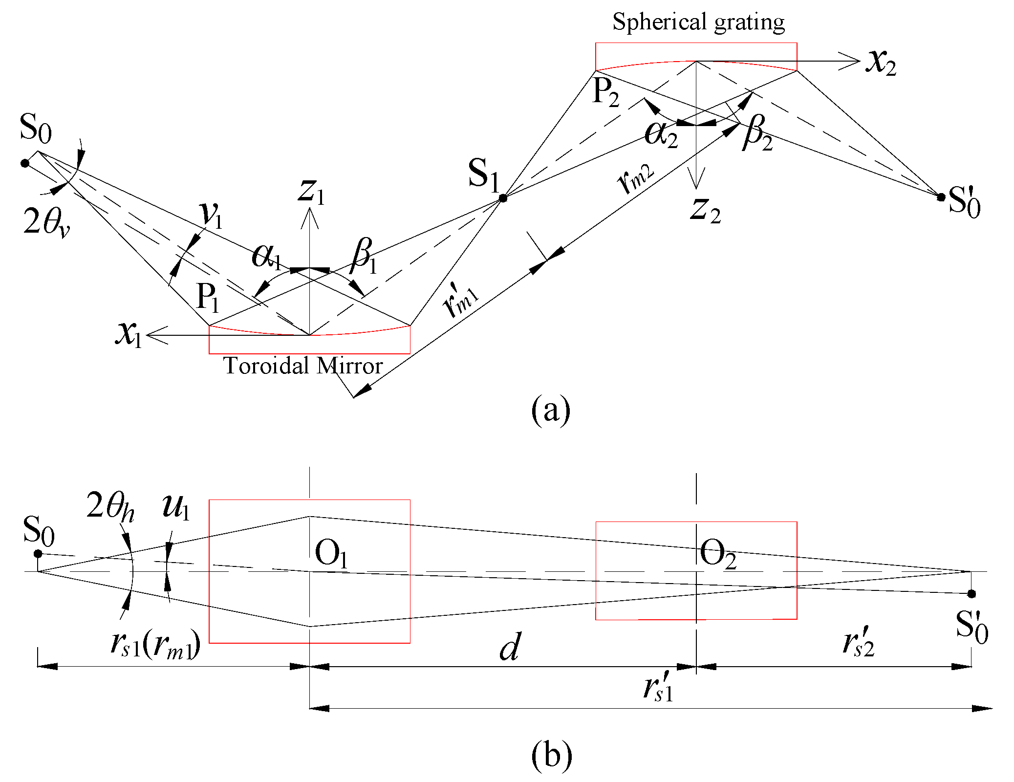
The optical path diagram of a plane-symmetric optical system with meridional and sagittal field angle light sources is shown in Figure 1. S0 is an off-axis object point with meridional and sagittal field angles, v, u, in the object space; χ η z and x y z are the coordinate systems of the optical surface and pupil, and O and P ¯ are their respective vertices; α and β are the incidence and reflection angles of the base ray O O O ; in addition, u and v are the sagittal and meridional field angles of the image point in image space S1.
For the plane-symmetric optical system, we need to define the general form of a plane-symmetric surface, which can be expressed as follows [17]:
z = i = 0 j = 0 c i , j χ i η j ,   c 0 , 0 = c 1 , 0 = 0 ;   j = even .
Since this paper studies the third-order intrinsic aberration modification with second-order accuracy transfer of pupil coordinates and the extrinsic aberration of a plane-symmetric optical system with a two-dimensional field light source, the fourth-order wave aberration needs to be studied in the following. Therefore, Equation (1) should be expanded to fourth order with respect to the χ and η series, and the equation for a plane-symmetric optical surface should be
z = c 2 , 0 χ 2 + c 0 , 2 η 2 + c 3 , 0 χ 3 + c 1 , 2 χ η 2 + c 4 , 0 χ 4 + c 2 , 2 χ 2 η 2 + c 0 , 4 η 4 ,
For the plane-symmetric optical system, a toroidal surface can be applied to obtain information for the meridional and sagittal planes; thus, its figure coefficients c i , j are given as follows:
c 2 , 0 = 1 2 R , c 0 , 2 = 1 2 ρ , c 3 , 0 = 0 , c 1 , 2 = 0 , c 4 , 0 = 1 8 R 3 , c 0 , 4 = 1 8 ρ 3 , c 2 , 2 = 1 4 R 2 ρ .
where R and ρ are the curvature radius of the meridional and sagittal planes of the toroidal surface, respectively.

3. Third-Order Intrinsic Aberration with Linear Transfer of Pupil Coordinates

For the plane-symmetric optical system with meridional and sagittal field angle light sources, the fourth-order wave aberration expression should be [15]
W = i j k h 4 w i j k h x i y j u k v h         ( i + j + k + h 4 ) .
where x and y are the pupil coordinates on the optical surface of the optical element, and i , j , k and h are the corresponding orders of x , y , u and v , respectively.
In accordance with the aberration theory of a plane-symmetric optical system, we applied the optical path function to derive the wave aberration expressions; thus, if the optical element is a grating, the groove function for the grating will also contribute to the wave aberration. For a holographic and mechanical rule grating, the groove function is [15]
n = χ σ + Γ σ ( n 20 2 χ 2 + n 02 2 η 2 + n 30 2 χ 3 + n 12 2 χ η 2 + n 40 8 χ 4 + n 22 4 χ 2 η 2 + n 04 8 η 4 ) = i j k h 4 ( Γ σ ) N i j k h x i y j u k v h ,  
where σ represents the groove spacing of the grating at the vertex, and Γ and n i j are given by Equations (20)–(22) and (A5) of reference [18].
Therefore, the wave aberration coefficients, w i j k h , of Equation (4) can be calculated as follows:
w i j k h = M i j k h ( α , r m , r s , l m , l s ) + ( 1 ) k + h ( cos α cos β ) h M i j k h ( β , r m , r s , l m , l s ) + Λ N i j k h ,
In Equation (6), M i j k h ( α , r m , r s , l m , l s ) denotes the wave aberration of an object space, and their corresponding expressions are given in Appendix A of reference [1]; Λ = ( m λ / σ ) Γ , m and λ are the diffraction order and working wavelength of the grating; the function expressions N i j k h are listed in Table 1. However, if the optical element is a mirror, the last term of the right side of Equation (6), Λ N i j k h , does not need to be considered and should be zero.
In order to calculate the wave aberration W of Equation (4), we need to apply the first-order wave aberration coefficients w 1000 = 0 to determine the incidence and reflection angles of the base ray, α and β; the second-order wave aberration coefficients w 1001 = 0 and w 0110 = 0 will need to be applied to determine the position of the principal ray (or pupil position) in the meridional and sagittal plane in the object and image space, l m , l s , l m and l s ; the second-order wave aberration coefficients w 2000 = 0 and w 0200 = 0 will need to be applied to determine meridional and sagittal focal distances in object and image space, r m , r s , r m and r s , respectively [15]. Therefore, the image aberration on the image plane of the optical system contributed by the wave aberration of Equation (4) should be
W = w 3000 x 3 + w 1200 x y 2 + w 4000 x 4 + w 2200 x 2 y 2 + w 0400 y 4 + w 1110 x y u + w 2110 x 2 y u + w 0310 y 3 u + w 1020 x u 2 + w 2020 x 2 u 2 + w 0220 y 2 u 2 + w 0130 y u 3 + w 2001 x 2 v + w 0201 y 2 v + w 1111 x y u v + w 3001 x 3 v + w 1201 x y 2 v + w 1002 x v 2 + w 2002 x 2 v 2 + w 0202 y 2 v 2 + w 1003 x v 3 + w 0111 y u v + w 0112 y u v 2 + w 1021 x u 2 v ,
For a soft X-ray and vacuum ultraviolet optical system consisting of g optical surfaces, the aperture-ray coordinates on each optical surface need to transfer to those on last optical surface. The total fourth-order wave aberration of optical system is [15]
W = n = 1 g i j k h 4 w i j k h ( n ) x n i y n j u n k v n h ,
Applying the ray geometric relation and polynomial fitting method, we can obtain the linear transfer relationship of the pupil coordinates between adjacent optical surfaces; these are given in as follows:
x n = A n x n + 1 , y n = B n y n + 1 , u n = ( 1 / B n ) u n + 1 , v n = C n v n + 1 ,
With these coefficients: A n = r m ( n ) cos α n + 1 / ( r m ( n + 1 ) cos β n ) , B n = r s ( n ) / r s ( n + 1 ) , C n = r m ( n + 1 ) cos β n / ( r m ( n ) cos α n ) .
Therefore, applying the transfer relationship given in Equation (9), the wave aberration calculation expression of Equation (8) can be rewritten as
W = i j k h 4 w i j k h T x g i y g j u g k v g h ( i + j + k + h 4 ) ,
where w i j k h T = n = 1 g 1 w i j k h ( n ) A n | g i B n | g j k C n | g h + w i j k h ( g ) ; the coefficients of A n | g , B n | g and C n | g are
A n | g = A n A n + 1 A g 1 , B n | g = B n B n + 1 B g 1 , C n | g = C n C n + 1 C g 1 .
In addition, the aberration of a plane-symmetric optical system is related to the pupil position of each element, and the pupil-position transfer equations in the meridional and sagittal plane of the adjacent optical surfaces are [15]
l m ( n + 1 ) = C n 2 l m ( n ) + ( r m ( n + 1 ) r m ( n ) ) d n , l s ( n + 1 ) = l s ( n ) B n 2 + d n B n .
According to the above discussions, the third-order aberration expressions of the plane-symmetric optical system should be
x = d 1000 x + d 2000 x 2 + d 0200 y 2 + d 0110 y u + d 3000 x 3 + d 1200 x y 2 + d 0020 u 2 + d 1110 x y u + d 1020 x u 2 + d 0001 v + d 1001 x v + d 0002 v 2 + d 2001 x 2 v + d 1002 x v 2 + d 0201 y 2 v + d 0111 y u v + d 0021 u 2 v + d 0003 v 3 , y = h 0100 y + h 1100 x y + h 2100 x 2 y + h 0010 u + h 1010 x u + h 2010 x 2 u + h 0210 y 2 u + h 0120 y u 2 + h 0300 y 3 + h 0030 u 3 + h 0101 y v + h 0011 u v + h 1101 x y v + h 1011 x u v + h 0102 y v 2 + h 0012 u v 2 ,
The aberration coefficients of Equation (13), d i j k h and h i j k h , are listed in Appendix A of reference [15].

4. Intrinsic Aberration Modification Caused by Second-Order Accuracy Transfer of Pupil Coordinates and Extrinsic Aberration

In Section 2, we discussed the calculation method for intrinsic aberration in the case of a linear transfer relationship of the pupil coordinates and given the corresponding aberration expressions. However, for a multi-element optical system, if the meridional curvature radius of the optical element is small, or the field angle of the object point of the optical system is large, the effect of pupil coordinate transfer using nonlinear relation is usually not neglected; if we nevertheless applied the linear transfer relation expression given in Equation (9) to calculate the aberration in this case, it will result in a serious error; therefore, in order to improve aberration accuracy, we adopted the second-order transfer relationship of the pupil coordinates on the adjacent optical surfaces in this paper. In addition, for a multi-element optical system, the object point of the latter optical surface will not be an ideal point due to the effect of the aberration of the preceding optical surfaces; the variable quantity of the pupil coordinates of the optical surface caused by the aberration of the preceding optical surfaces is regarded as an extrinsic aberration.
Figure 2 shows the optical path diagram of an aperture ray passing through a soft X-ray and vacuum ultraviolet optical system consisting of two optical surfaces. The rays S0O1O2 and S0P1P2 are the principal ray and aperture ray, and the aperture ray S0P1P2 intersects optical surface G1, G2 at P1, P2; xiyizi (i = 1, 2) and x 1 y 1 z 1 are the coordinate systems of optical surface Gi and image plane 1 at a distance of r 0 from optical surface G1; The coordinates of B1 and B 1 represent the aperture-ray coordinates on G2 with and without the extrinsic aberration, respectively.
In the following we first discuss the second-order accuracy transfer relationship of the pupil coordinates between adjacent optical surfaces. The relation expressions of coordinates P1(x1, y1) and P2(x2, y2) are assumed to be
x 2 = i j k h 2 a ¯ i j k h x 1 i y 1 j u 1 k v 1 h ,         y 2 = i j k h 2 b ¯ i j k h x 1 i y 1 j u 1 k v 1 h .
And then Next, combining these with the ray equation for S 0 P 1 B 1 using the polynomial fitting method, yields the second-order mapping relationship between the coordinates P1(x1, y1) and P2(x2, y2) as follows:
x 2 = 1 A 1 x 1 + 2 Γ 1 y 1 u 1 + Γ 2 x 1 v 1 + Γ 3 A 1 x 1 2 + Γ 4 y 1 2 , y 2 = 1 B 1 y 1 + Γ 5 x 1 u 1 + Γ 6 y 1 v 1 + Γ 7 r s 1 x 1 y 1 .
In Equation (15), since for the dimension of a source (approximately 1 mm) such as a synchrotron radiation light source or laser, the meridional and sagittal field angles u and v of the object point are usually very small, terms only containing u and v are ignored; the corresponding coefficients are given as
Γ 1 = c 0 , 2 ( 2 ) l 2 tan α 2 c 0 , 2 ( 1 ) l 1 tan β 1 A 1 , Γ 2 = 2 C 1 l m 1 r m 1 cos α 2 ( tan α 2 cos β 1 ( c 2 , 0 ( 2 ) r m 2 cos α 2 1 ) + sin β 1 ) cos α 1 cos α 2 ( tan α 2 + r m 2 r m 1 ( 2 tan α 2 tan β 1 ) )         2 cos α 1 A 1 cos β 1 ( c 2 , 0 ( 1 ) l m 1 sin β 1 cos 2 α 1 c 2 , 0 ( 2 ) d 1 tan α 2 cos α 2 ) , Γ 3 = c 2 , 0 ( 2 ) tan α 2 A 1 c 2 , 0 ( 1 ) tan β 1 + sin ( β 1 α 2 ) r m 1 cos α 2 , Γ 4 = c 0 , 2 ( 2 ) tan α 2 B 1 2 c 0 , 2 ( 1 ) tan β 1 A 1 , Γ 5 = ( sin β 1 B 1 ( 1 + l s 1 r s 1 ) + B 1 sin α 2 A 1 ( 1 l s 2 r s 2 ) ) , Γ 6 = l m 1 r s 1 ( sin β 1 B 1 cos α 1 C 1 tan α 2 ) cos α 1 tan α 2 cos β 1 ( 1 + 1 B 1 ) , Γ 7 = sin α 2 A 1 sin β 1 B 1 .
According to the aberration descriptions of a multi-element optical system in the first paragraph of this section, the actual aberration is the sum of the intrinsic aberration and the extrinsic aberration; in the following we will discuss the calculation method for extrinsic aberration. Firstly, based on third-order intrinsic aberration calculation expressions of a plane-symmetric optical system with a two-dimensional field light source, we applied the wave aberration of optical surface G1 to calculate the resulting aberration on the image plane positioned at optical surface G2 (i.e., in the case of r 0 = d in Figure 2). The amount of change in the pupil coordinates with second-order accuracy transfer on the entrance wavefront of optical surface G2 caused by extrinsic aberration can be calculated as follows:
Δ x 1 = 3 d w 3000 ( 1 ) cos β 1 x 1 2 + d w 1200 ( 1 ) cos β 1 y 1 2 + d w 1110 ( 1 ) cos β 1 y 1 u 1 + d w 1020 ( 1 ) cos β 1 u 1 2 + 2 d w 2001 ( 1 ) cos β 1 x 1 v 1 + d w 1002 ( 1 ) cos β 1 v 1 2 , Δ y 1 = 2 d w 1200 ( 1 ) x 1 y 1 + d w 1110 ( 1 ) x 1 u 1 + 2 d w 0201 ( 1 ) y 1 2 v 1 + d w 0111 ( 1 ) u 1 v 1 .
Next, the Δ x 1 and Δ y 1 coordinates need to be converted to the coordinate system of optical surface G2; the transfer relationship between them is
Δ x 2 = Δ x 1 cos α 2 ,         Δ y 2 = Δ y 1 .
According to the above discussion, the actual pupil coordinates of the ray that impinges on the optical surface G2 should be
x 2 = x 2 + Δ x 2 ,         y 2 = y 2 + Δ y 2 .
Therefore, the actual total wave aberration of a soft X-ray and vacuum ultraviolet optical system consisting of two optical surfaces is
W T = W 1 + W 2 = i j k h 4 w i j k h ( 1 ) x 1 j y 1 j u 1 k v 1 h + i j k h 4 w i j k h ( 2 ) x 2 j y 2 j u 2 k v 2 h .
We then applied the wave aberration calculated in Equation (20), W T , to the aberration calculation of the optical system. In order to simplify the intrinsic aberration modification caused by the second-order accuracy transfer of the pupil coordinates and extrinsic aberration expressions, the pupil coordinates on the optical surface and the sagittal and meridional field angles of G1, x 1 , y 1 , u 1 , v 1 , were applied to calculate the aberration values mentioned above. However, the intrinsic aberration in the case of the linear accuracy transfer of the pupil coordinates still incorporates x 2 , y 2 , u 2 , v 2 . Therefore, the final coordinates of the ray impinging on the image plane are
X = i j k h 3 ( d i j k h x 2 i y 2 j u 2 k v 2 h + d i j k h x 1 i y 1 j u 1 k v 1 h ) ,         Y = i j k h 3 ( h i j k h x 2 i y 2 j u 2 k v 2 h + h i j k h x 1 i y 1 j u 1 k v 1 h ) ,
where d i j k h and h i j k h denote the intrinsic aberration coefficients obtained via the linear transfer of the pupil coordinates; d i j k h and h i j k h are intrinsic aberration modification coefficients due to the second-order accuracy transfer of the pupil coordinates and to the extrinsic aberration coefficients; their expressions are given in Appendix A. Compared to the case of a soft X-ray vacuum ultraviolet optical system with a one-dimensional field light source, this system has the following additional fourteen aberration items: d 1001 , d 0002 , d 2001 , d 1002 , d 0201 , d 0111 , d 0021 , d 0003 , h 0101 , h 0011 , h 1101 , h 1011 , h 0102 and h 0112 .

5. Simulation Experiment Validation

In Section 3, we derive the intrinsic aberration modification due to the second-order accuracy transfer of pupil coordinates and to the extrinsic aberration expressions. In the following we will apply these aberration expressions and the ray-tracing software Shadow to calculate a spot diagram on the image plane of the two design examples of a soft X-ray and vacuum ultraviolet system with meridional and sagittal field angle light sources and to validate these expressions. Considering that the aberration expression derived in this paper can be used for analyzing the imaging performance of a soft X-ray and vacuum ultraviolet system with meridional and sagittal field angle light sources consisting of a grating or a different figure mirror, we thus selected the first optical system (optical system I) using Tondello’s spectrograph: the first optical element is a torodial mirror and the second optical element is a spherical-grating monochromator; its optical path diagram is shown in Figure 3. The divergence angles of the light beam emitted from the source of optical system I in the meridional and sagittal planes, 2 θ v and 2 θ h , are 10 mrad and 20 mrad, respectively; the groove density of the spherical grating is 600 grooves/mm and works in the a + 1 diffraction order at a wavelength of 4.4 nm; the other optical parameters in Figure 3 are listed in 
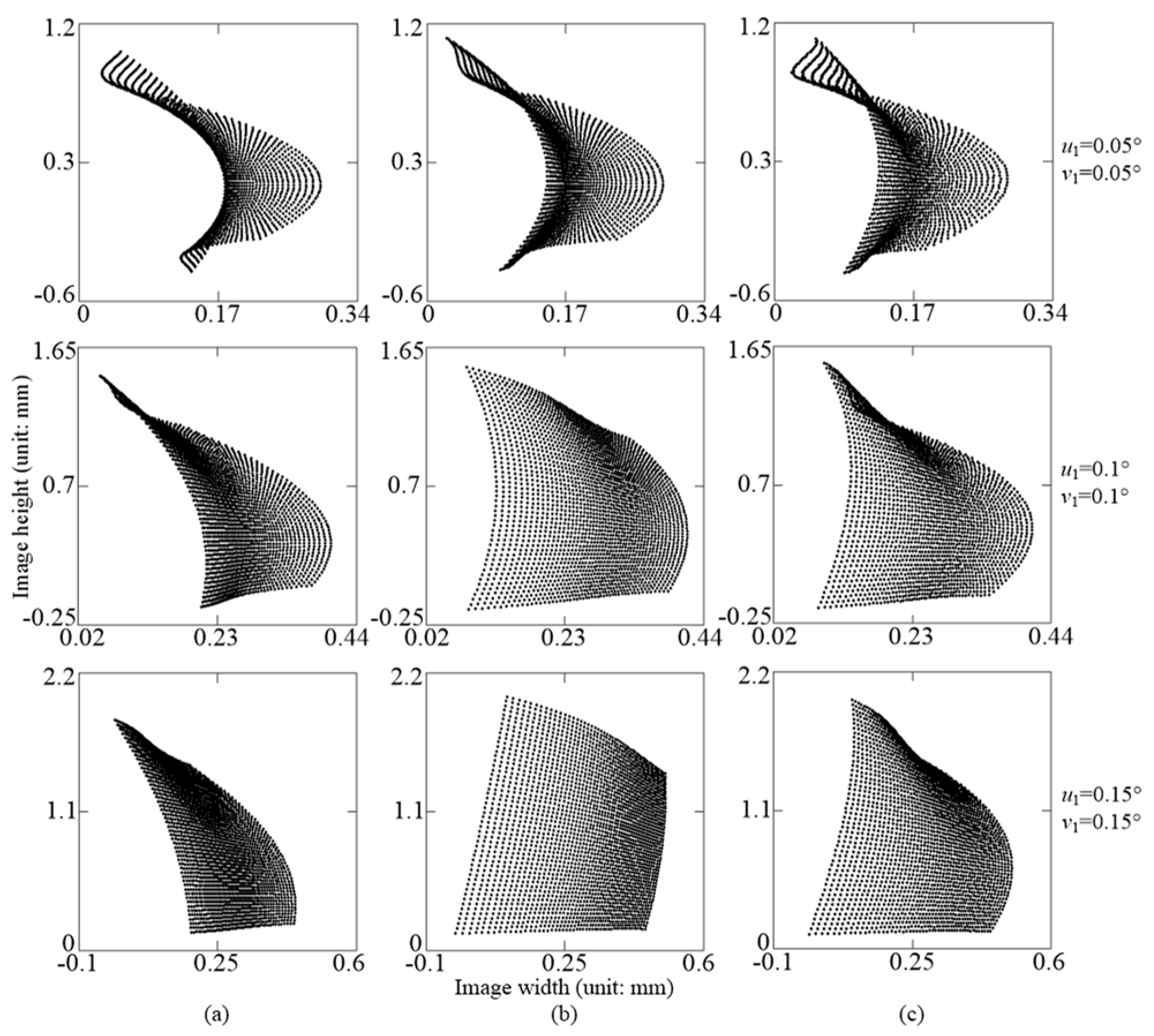
Table 2. In order to further validate these aberration expressions, optical system II was modified such that the curvature radius of the meridional plane of the toroidal mirror was reduced to the basis of optical system I and was set 25 cm. The other parameters are consistent with those of optical system I. In addition, in the following spot diagram calculations of the image planes of optical systems I and II, the positions of the entrance pupil in the meridional and sagittal planes are both on the first optical surface; and the meridional and sagittal field angles are assumed to be u 1 = 0.05 0 ,   v 1 = 0.05 0 , u 1 = 0.1 0 ,   v 1 = 0.1 0 and u 1 = 0.15 0 ,   v 1 = 0.15 0 .
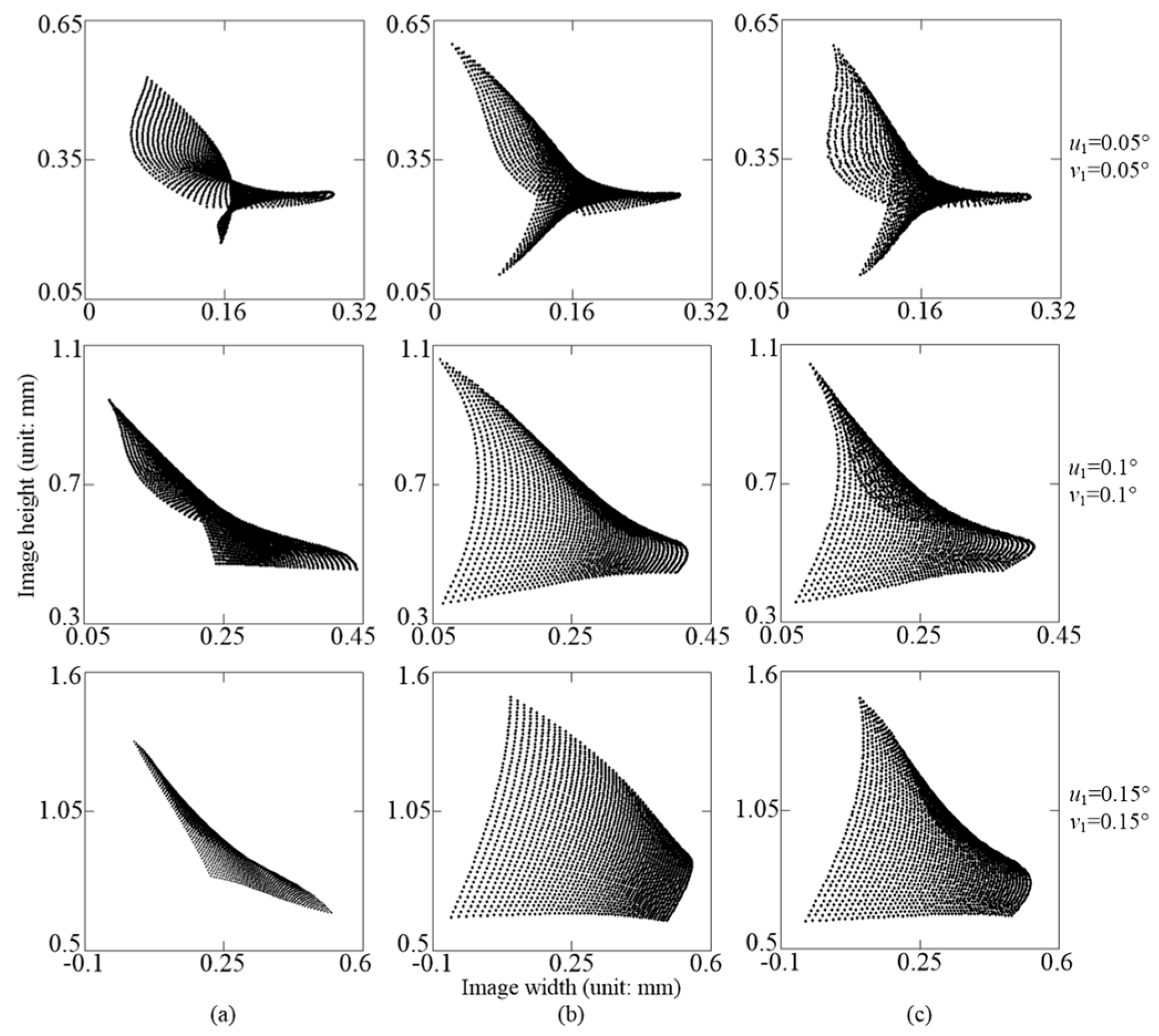
Ray spot diagrams of optical systems I and II using the three calculation methods based on the optical structure parameters given in the above are shown in Figure 4 and Figure 5, respectively; and Figure 4a,b and Figure 5a,b are the calculation results using the intrinsic aberration with linear transfer of the pupil coordinates, d i j k h and h i j k h , and adding the intrinsic aberration modification coefficients due to the second-order accuracy transfer of the pupil coordinates and to the extrinsic aberration coefficients, d i j k h and h i j k h , respectively. Figure 4c and Figure 5c shows the calculation results obtained using the ray-tracing software Shadow; their field angles are listed on the right side of figure.
For a soft X-ray and vacuum ultraviolet optical system with meridional and sagittal field angle light sources, we compared the shape and size of the ray spot diagrams given in Figure 4 and Figure 5 to the corresponding calculation results obtained using the ray-tracing software Shadow. In this way, we were able to determine that the results calculated on the basis of the intrinsic aberration coefficients with linear transfer of pupil coordinates d i j k h and h i j k h contained serious errors. The calculation accuracy obtained by taking the intrinsic aberration modification coefficients due to second-order accuracy transfer of the pupil coordinates and adding these to extrinsic aberration coefficients d i j k h and h i j k h , on the other hand, was found to be sufficient; the small differences between the two sets of results are mainly due to the higher-order aberration contribution or to the higher-order coordinate components in the transfer of the pupil coordinates between the adjacent optical surfaces. Based on the above discussions, the calculation accuracy of third-order intrinsic aberration modification with second-order accuracy transfer of the pupil coordinates and extrinsic aberration expressions is satisfactory.

6. Conclusions

We conducted a detailed study on third-order intrinsic aberration modification with second-order accuracy transfer of pupil coordinates between adjacent optical surfaces, as well as on the extrinsic aberration calculation method of a soft X-ray and vacuum ultraviolet system with meridional and sagittal field angle light sources; we also derived their corresponding aberration expressions. The results can be applied to analyses of aberration in these kinds of optical systems using either a grating or different figure mirror. We also applied the aberration expressions derived in this paper and used the ray-tracing software Shadow to calculate ray spot diagrams on the image plane for two examples of these kinds of optical systems. Comparing this to the calculation results showed that the accuracy of the aberration expressions is satisfactory. The method discussed in this paper can be extended to the study of intrinsic aberration modification with second-order accuracy transfer of pupil coordinates and to the extrinsic aberration of optical systems with more optical elements. By comparing this to results from ray-tracing software, this paper provides an analytical analysis of aberration expressions for the purpose of studying aberration in plane-symmetric optical systems and will be helpful in the determination of initial structure parameters and in the optimization of optical parameters of X-ray and vacuum ultraviolet systems with meridional and sagittal field angle light sources.

Author Contributions

Conceptualization, methodology, formal analysis and writing-original draft preparation, Y.C., Z.S. and L.L.; writing—review and editing, Y.C. and Z.S. All authors have read and agreed to the published version of the manuscript.

Funding

This research was funded by the Project of National Nature Science Foundation of China (62205168); Young and Middle-Aged Teachers’ Educational Research Projects of Fujian Province of China (JAT220294); Natural Science Foundation of Fujian Province (2020J01916).

Data Availability Statement

Data are contained within the article.

Conflicts of Interest

The authors declare no conflicts of interest.

Appendix A. Third-Order Intrinsic Aberration Modification Coefficients Due to Second-Order Accuracy Transfer of Pupil Coordinates and Extrinsic Aberration Coefficients

d 2000 = Λ m ( 2 ) cos β 2 ( 3 d 1 w 3000 ( 1 ) cos β 1 cos α 2 Γ 3 A 1 ) ,
d 3000 = 6 r 0 Γ 3 A 1 2 cos β 2 ( A 1 3 w 3000 ( 1 ) w 3000 ( 2 ) ) 18 r 0 d 1 w 3000 ( 1 ) w 3000 ( 2 ) A 1 cos β 1 cos α 2 cos β 2 + 2 Λ m ( 2 ) sin β 2 ( 3 d 1 w 3000 ( 1 ) A 1 cos β 1 cos α 2 Γ 3 A 1 2 ) ( c 2 , 0 ( 2 ) cos β 2 r m 2 ) ,
d 0200 = Λ m ( 2 ) cos β 2 ( d 1 w 1200 ( 1 ) cos β 1 cos α 2 Γ 4 ) ,
d 1200 = 2 r 0 cos β 2 [ Γ 6 B 1 r s 1 ( A 1 B 1 2 w 1200 ( 1 ) w 1200 ( 2 ) ) A 1 Γ 3 w 1200 ( 1 ) ] + 6 r 0 Γ 4 w 300 ( 2 ) A 1 cos β 2 4 r 0 d 1 w 1200 ( 1 ) w 1200 ( 2 ) B 1 cos β 2 6 r 0 d 1 w 1200 ( 1 ) w 3000 ( 2 ) A 1 cos β 1 cos α 2 cos β 2 + 2 d 1 Λ m ( 2 ) sin β 2 [ 2 c 0 , 2 ( 2 ) B 1 1 A 1 cos β 1 cos α 2 ( cos β 2 r m 2 c 2 , 0 ( 2 ) ) ] w 1200 ( 1 ) + 2 Λ m ( 2 ) sin β 2 ( Γ 6 c 0 , 2 ( 2 ) B 1 r s 1 Γ 4 c 2 , 0 ( 2 ) A 1 ) + Λ m ( 2 ) Γ 4 sin 2 β 2 A 1 r m 2 ,
d 0110 = Λ m ( 2 ) cos β 2 ( d 1 w 1110 ( 1 ) cos β 1 cos α 2 2 Γ 1 ) ,
d 0020 = d 1 Λ m ( 2 ) cos β 2 w 1020 ( 1 ) B 1 2 cos β 1 cos α 2 ,
d 1110 = 2 r 0 Γ 5 B 1 cos β 2 ( A 1 B 1 2 w 1200 ( 1 ) w 1200 ( 2 ) ) + 12 r 0 Γ 1 w 3000 ( 2 ) A 1 cos β 2 + r 0 cos β 2 [ B 1 Γ 6 r s 1 ( A 1 w 1110 ( 1 ) w 1110 ( 2 ) ) 2 A 1 Γ 3 w 1110 ( 1 ) ] 6 r 0 d 1 w 1110 ( 1 ) w 3000 ( 2 ) A 1 cos β 1 cos α 2 cos β 2 2 r 0 d 1 B 1 cos β 2 ( B 1 2 w 1200 ( 1 ) w 1110 ( 2 ) + w 1110 ( 1 ) w 1200 ( 2 ) ) + 2 d 1 Λ m ( 2 ) sin β 2 A 1 [ A 1 c 0 , 2 ( 2 ) B 1 + 1 cos β 1 cos α 2 ( c 2 , 0 ( 2 ) cos β 2 r m 2 ) ] w 1110 ( 1 ) + 4 B 1 d 1 Λ m ( 2 ) l s 2 c 0 , 2 ( 2 ) sin β 2 w 1200 ( 1 ) 4 Λ m ( 2 ) Γ 1 sin β 2 A 1 ( c 2 , 0 ( 2 ) cos β 2 r m 2 ) + 2 Λ m ( 2 ) c 0 , 2 ( 2 ) sin β 2 ( B 1 l s 2 Γ 6 r s 1 + Γ 5 B 1 ) ,
d 1020 = r 0 B 1 Γ 5 cos β 2 ( A 1 w 1110 ( 1 ) w 1110 ( 2 ) ) + 2 B 1 d 1 Λ m ( 2 ) l s 2 c 0 , 2 ( 2 ) sin β 2 w 1110 ( 1 ) 2 r 0 A 1 Γ 3 w 1020 ( 1 ) cos β 2 r 0 B 1 d 1 cos β 2 w 1110 ( 1 ) w 1110 ( 2 ) 6 r 0 d 1 w 1020 ( 1 ) w 3000 ( 2 ) A 1 cos β 1 cos α 2 cos β 2 + 2 d 1 Λ m ( 2 ) sin β 2 A 1 cos β 1 cos α 2 ( c 2 , 0 ( 2 ) cos β 2 r m 2 ) w 1020 ( 1 ) + 2 B 1 Λ m ( 2 ) Γ 5 l s 2 c 0 , 2 ( 2 ) sin β 2 ,
d 1001 = Λ m ( 2 ) cos β 2 ( 2 d 1 w 2001 ( 1 ) cos β 1 cos α 2 Γ 2 ) ,
d 0002 = Λ m ( 2 ) d 1 cos β 2 cos β 1 cos α 2 w 1002 ( 1 ) ,
d 2001 = 6 Γ 2 r 0 A 1 cos β 2 ( 2 A 1 3 w 3000 ( 1 ) w 3000 ( 2 ) ) 2 Γ 3 r 0 A 1 C 1 cos β 2 [ ( 2 A 1 2 C 1 w 2001 ( 1 ) w 2001 ( 2 ) ) w 2002 ( 2 ) ] 6 r 0 d 1 A 1 C 1 cos β 1 cos α 2 cos β 2 × ( A 1 w 3000 ( 1 ) w 2001 ( 2 ) + 2 C 1 w 2001 ( 1 ) w 3000 ( 2 ) ) 3 d 1 Λ m ( 2 ) C 1 [ tan β 2 cos β 1 2 Γ y cos β 1 cos α 2 ( c 2 , 0 ( 2 ) cos β 2 r m 2 ) ] w 3000 ( 1 ) + 4 d 1 Λ m ( 2 ) sin β 2 A 1 cos β 1 cos α 2 ( c 2 , 0 ( 2 ) cos β 2 r m 2 ) w 2001 ( 1 ) 2 Λ m ( 2 ) A 1 ( Γ 3 Γ y C 1 + Γ 2 sin β 2 ) ( c 2 , 0 ( 2 ) cos β 2 r m 2 ) + Γ 3 Λ m ( 2 ) cos α 2 tan β 2 A 1 C 1 ,
d 1002 = 2 Γ 2 r 0 C 1 cos β 2 ( 3 A 1 2 C 1 w 2001 ( 1 ) w 2001 ( 2 ) ) 2 r 0 C 1 cos β 2 ( A 1 C 1 Γ 3 w 1002 ( 1 ) Γ 2 w 2002 ( 2 ) ) 2 d 1 r 0 A 1 C 1 cos β 2 cos β 1 cos α 2 ( 2 A 1 w 2001 ( 1 ) w 2001 ( 2 ) + 3 C 1 w 1002 ( 1 ) w 3000 ( 2 ) ) + 2 d 1 Λ m ( 2 ) cos β 1 cos α 2 ( sin β 2 A 1 w 1002 ( 1 ) + 2 Γ y C 1 w 2001 ( 1 ) ) ( c 2 , 0 ( 2 ) cos β 2 r m 2 ) + Λ m ( 2 ) tan β 2 C 1 ( Γ 2 cos α 2 2 d 1 cos β 1 w 2001 ( 1 ) ) 2 Γ 2 Γ y Λ m ( 2 ) C 1 ( c 2 , 0 ( 2 ) cos β 2 r m 2 ) ,
d 0201 = 2 r 0 B 1 cos β 2 ( A 1 2 B 1 Γ 2 w 1200 ( 1 ) + Γ 6 w 1200 ( 2 ) ) + 2 A 1 B 1 Γ 7 r 0 r s 1 cos β 2 w 0201 ( 1 ) + 2 Γ 4 r 0 C 1 cos β 2 ( w 2001 ( 2 ) + w 2002 ( 2 ) ) 4 d 1 r 0 B 1 cos β 2 w 0201 ( 1 ) w 1200 ( 2 ) + 4 d 1 Λ m ( 2 ) c 0 , 2 ( 2 ) sin β 2 B 1 w 0201 ( 1 ) 2 d 1 r 0 C 1 cos β 1 cos α 2 cos β 2 w 1200 ( 1 ) w 2001 ( 2 ) + 2 d 1 Γ y Λ m ( 2 ) C 1 cos β 1 cos α 2 ( c 2 , 0 ( 2 ) cos β 2 r m 2 ) w 1200 ( 1 ) d 1 Λ m ( 2 ) tan β 2 C 1 cos β 1 w 1200 ( 1 ) 2 Γ 4 Γ y Λ m ( 2 ) C 1 ( c 2 , 0 ( 2 ) cos β 2 r m 2 ) + 2 Γ 6 Λ m ( 2 ) c 0 , 2 ( 2 ) sin β 2 B 1 + Γ 4 Λ m ( 2 ) cos α 2 tan β 2 C 1 ,
d 0111 = 4 Γ 1 r 0 C 1 cos β 2 ( w 2001 ( 2 ) + w 2002 ( 2 ) ) r 0 cos β 2 ( 2 A 1 2 Γ 2 w 1110 ( 1 ) + B 1 Γ 6 w 1110 ( 2 ) ) + A 1 B 1 r 0 cos β 2 ( 2 Γ 5 w 0201 ( 1 ) + Γ 7 r s 1 w 0111 ( 1 ) ) 2 d 1 r 0 C 1 cos β 1 cos α 2 cos β 2 w 1110 ( 1 ) w 2001 ( 2 ) 2 d 1 r 0 B 1 cos β 2 ( B 1 2 w 0201 ( 1 ) w 1110 ( 2 ) + w 0111 ( 1 ) w 1200 ( 2 ) ) + 2 Γ y Λ m ( 2 ) C 1 ( d 1 cos β 1 cos α 2 w 1110 ( 1 ) 2 Γ 1 ) ( c 2 , 0 ( 2 ) cos β 2 r m 2 ) d 1 Λ m ( 2 ) tan β 2 C 1 cos β 1 w 1110 ( 1 ) + 2 d 1 Λ m ( 2 ) c 0 , 2 ( 2 ) sin β 2 B 1 w 0111 ( 1 ) + 2 B 1 Λ m ( 2 ) c 0 , 2 ( 2 ) l s 2 sin β 2 ( 2 d 1 w 0201 ( 1 ) + Γ 6 ) + 2 Γ 1 Λ m ( 2 ) cos α 2 tan β 2 C 1 ,
d 0021 = A 1 r 0 cos β 2 ( 2 A 1 Γ 2 w 1020 ( 1 ) B 1 Γ 5 w 0111 ( 1 ) ) d 1 r 0 cos β 2 ( B 1 w 0111 ( 1 ) w 1110 ( 2 ) + 2 C 1 cos β 1 cos α 2 w 1020 ( 1 ) w 2001 ( 2 ) ) + 2 d 1 Γ y Λ m ( 2 ) C 1 cos β 1 cos α 2 ( c 2 , 0 ( 2 ) cos β 2 r m 2 ) w 1020 ( 1 ) d 1 Λ m ( 2 ) tan β 2 C 1 cos β 1 w 1020 ( 1 ) + 2 B 1 d 1 Λ m ( 2 ) c 0 , 2 l s 2 sin β 2 w 0111 ( 1 ) ,
d 0003 = 2 A 1 2 Γ 2 r 0 cos β 2 w 1002 ( 1 ) 2 d 1 r 0 C 1 cos β 1 cos α 2 cos β 2 w 1002 ( 1 ) w 2001 ( 2 ) + d 1 Λ m ( 2 ) C 1 cos β 1 ( 2 Γ y cos α 2 ( c 2 , 0 ( 2 ) cos β 2 r m 2 ) tan β 2 ) w 1002 ( 1 ) ,
h 1100 = Λ s ( 2 ) ( 2 d 1 w 1200 ( 1 ) + Γ 6 r s 1 ) ,
h 2100 = 2 r 0 A 1 [ Γ 6 r s 1 ( A 1 B 1 2 w 1200 ( 1 ) w 1200 ( 2 ) ) + Γ 3 w 1200 ( 2 ) B 1 ] + 6 r 0 A 1 B 1 Γ 4 w 3000 ( 1 ) + 6 r 0 d 1 B 1 cos β 1 cos α 2 w 3000 ( 1 ) w 1200 ( 2 ) + 4 r 0 d 1 w 1200 ( 1 ) w 1200 ( 2 ) A 1 + d 1 Λ s ( 2 ) sin β 2 r s 2 ( 2 w 1200 ( 1 ) A 1 + 3 w 3000 ( 1 ) B 1 cos β 1 cos α 2 ) + Λ s ( 2 ) sin β 2 A 1 B 1 r s 2 ( B 1 Γ 6 r s 1 Γ 3 ) ,
h 1010 = Λ s ( 2 ) ( d 1 w 1110 ( 1 ) + Γ 5 ) ,
h 2010 = 2 r 0 Γ 5 w 1200 ( 2 ) A 1 + 6 r 0 A 1 B 1 Γ 1 w 3000 ( 1 ) r 0 B 1 ( B 1 Γ 6 w 1110 ( 1 ) r s 1 + Γ 3 w 1110 ( 2 ) A 1 ) + 3 r 0 B 1 d 1 w 3000 ( 1 ) w 1110 ( 2 ) cos β 1 cos α 2 + 2 r 0 d 1 w 1110 ( 1 ) w 1200 ( 2 ) A 1 + 3 B 1 d 1 Λ s ( 2 ) Λ l ( 2 ) sin β 2 cos β 1 cos α 2 w 3000 ( 1 ) + d 1 Λ s ( 2 ) sin β 2 A 1 r s 2 w 1110 ( 1 ) + Λ s ( 2 ) sin β 2 A 1 ( Γ 5 r s 2 B 1 Λ l ( 2 ) Γ 3 ) ,
h 0210 = 2 r 0 Γ 1 B 1 ( A 1 B 1 2 w 1200 ( 1 ) 2 w 1200 ( 2 ) ) + r 0 B 1 Γ 4 ( 2 A 1 w 111 ( 1 ) w 111 ( 2 ) ) + r 0 d 1 B 1 ( B 1 2 w 1200 ( 1 ) w 1110 ( 2 ) + 2 w 1110 ( 1 ) w 1200 ( 2 ) ) + d 1 Λ s ( 2 ) sin β 2 B 1 cos β 1 cos α 2 ( B 1 2 Λ l ( 2 ) w 1200 ( 1 ) + w 1110 ( 1 ) r s 2 ) Λ s ( 2 ) sin β 2 B 1 ( 2 Γ 1 r s 2 + B 1 2 Λ l ( 2 ) Γ 4 ) ,
h 0120 = 2 r 0 B 1 Γ 1 ( A 1 w 1110 ( 1 ) w 1110 ( 2 ) ) + 2 r 0 A 1 B 1 Γ 4 w 1020 ( 1 ) + r 0 d 1 B 1 cos β 1 cos α 2 ( B 1 2 w 1110 ( 1 ) w 1110 ( 2 ) + 2 w 1020 ( 1 ) w 1200 ( 2 ) ) + d 1 Λ s ( 2 ) sin β 2 B 1 cos β 1 cos α 2 ( B 1 2 Λ l ( 2 ) w 1110 ( 1 ) + w 1020 ( 1 ) r s 2 ) 2 B 1 Λ s ( 2 ) Λ l ( 2 ) Γ 1 sin β 2 ,
h 0300 = 2 r 0 Γ 4 B 1 ( A 1 B 1 2 w 1200 ( 1 ) w 1200 ( 2 ) ) + + 2 r 0 d 1 B 1 cos β 1 cos α 2 w 1200 ( 1 ) w 1200 ( 2 ) + Λ s ( 2 ) sin β 2 B 1 r s 2 ( d 1 w 1200 ( 1 ) cos β 1 cos α 2 Γ 4 ) ,
h 0030 = 2 r 0 A 1 B 1 Γ 1 w 1020 ( 1 ) 2 B 1 r 0 Γ 6 w 1110 ( 2 ) r 0 d 1 w 1020 ( 1 ) w 1110 ( 2 ) B 1 2 cos β 1 cos α 2 d 1 Λ s ( 2 ) Λ l ( 2 ) sin β 2 w 1020 ( 1 ) B 1 2 cos β 1 cos α 2 ,
h 0101 = Λ s ( 2 ) ( 2 d 1 w 0201 ( 1 ) + Γ 6 ) ,
h 0011 = d 1 Λ s ( 2 ) w 0111 ( 1 ) ,
h 1101 = 2 r 0 ( Γ 2 B 1 Γ 6 A 1 ) ( A 1 B 1 2 w 1200 ( 1 ) w 1200 ( 2 ) ) + 4 A 1 B 1 Γ 4 r 0 w 2001 ( 1 ) 2 Γ 7 r 0 C 1 r s 1 ( B 1 2 C 1 w 0201 ( 1 ) w 0201 ( 2 ) ) + 4 d 1 r 0 A 1 C 1 ( A 1 w 1200 ( 1 ) w 0201 ( 2 ) + C 1 w 0201 ( 1 ) w 1200 ( 2 ) ) + 4 d 1 r 0 B 1 cos β 1 cos α 2 w 2001 ( 1 ) w 1200 ( 2 ) + 2 d 1 Λ s ( 2 ) r s 2 ( sin β 2 A 1 w 0201 ( 1 ) + Γ y C 1 w 1200 ( 1 ) ) + 2 d 1 Λ s ( 2 ) sin β 2 B 1 r s 2 cos β 1 cos α 2 w 2001 ( 1 ) Λ s ( 2 ) sin β 2 A 1 B 1 r s 2 ( A 1 Γ 2 B 1 Γ 6 ) + Γ 7 Γ y Λ s ( 2 ) C 1 r s 1 r s 2 ,
h 1011 = B 1 Γ 2 r 0 ( A 1 w 1110 ( 1 ) w 1110 ( 2 ) ) B 1 2 Γ 6 r 0 w 1110 ( 1 ) + 4 A 1 B 1 Γ 1 r 0 w 2001 ( 1 ) + 2 Γ 5 r 0 C 1 w 0201 ( 2 ) B 1 2 Γ 7 r 0 r s 1 w 0111 ( 1 ) + 2 B 1 d 1 r 0 cos β 1 cos α 2 w 2001 ( 1 ) w 1110 ( 2 ) + 2 d 1 r 0 A 1 C 1 ( A 1 w 1110 ( 1 ) w 0201 ( 2 ) + C 1 w 0111 ( 1 ) w 1200 ( 2 ) ) + 2 B 1 d 1 Λ s ( 2 ) Λ l ( 2 ) sin β 2 cos β 1 cos α 2 w 2001 ( 1 ) + d 1 Λ s ( 2 ) r s 2 ( Γ y C 1 w 1110 ( 1 ) + sin β 2 A 1 w 0111 ( 1 ) ) + Γ 5 Γ y Λ s ( 2 ) C 1 r s 2 B 1 Γ 2 Λ s ( 2 ) Λ l ( 2 ) sin β 2 ,
h 0102 = 2 A 1 B 1 Γ 4 r 0 w 1002 ( 1 ) 2 Γ 6 r 0 C 1 ( B 1 2 C 1 w 0201 ( 1 ) w 0201 ( 2 ) ) + 2 d 1 r 0 B 1 C 1 ( 2 B 1 w 0201 ( 1 ) w 0201 ( 2 ) + C 1 cos β 1 cos α 2 w 1002 ( 1 ) w 1200 ( 2 ) ) + Γ y Λ s ( 2 ) C 1 r s 2 ( 2 d 1 w 0201 ( 1 ) + Γ 6 ) + d 1 Λ s ( 2 ) sin β 2 B 1 r s 2 cos β 1 cos α 2 w 1002 ( 1 ) ,
h 0012 = 2 A 1 B 1 Γ 1 r 0 w 1002 ( 1 ) B 1 2 Γ 6 r 0 w 0111 ( 1 ) + d 1 r 0 C 1 ( B 1 C 1 cos β 1 cos α 2 w 1002 ( 1 ) w 1110 ( 2 ) + 2 w 0111 ( 1 ) w 0201 ( 2 ) ) + B 1 d 1 Λ s ( 2 ) Λ l ( 2 ) sin β 2 cos β 1 cos α 2 w 1002 ( 1 ) + d 1 Γ y Λ s ( 2 ) C 1 r s 2 w 0111 ( 1 ) .

References

  1. Kleine, C.; Ekimova, M.; Winghart, M.O.; Eckert, S.; Reichel, O.; Lochel, H.; Probst, J.; Braig, C.; Seifert, C.; Erko, A.; et al. Highly efficient soft X-ray spectrometer for transient absorption spectroscopy with broadband table-top high harmonic sources. Struct. Dyn. 2021, 8, 034302. [Google Scholar] [CrossRef] [PubMed]
  2. Born, M.; Wolf, E. Principle of Optics; Cambridge University Press: Cambridge, UK, 2005. [Google Scholar]
  3. Beutler, H.G. The Theory of the concave grating. J. Opt. Soc. Am. 1945, 35, 311–350. [Google Scholar] [CrossRef]
  4. Noda, H.; Namioka, T.; Seya, M. Geometrical theory of the grating. J. Opt. Soc. Am. 1974, 64, 1031–1036. [Google Scholar] [CrossRef]
  5. Namioka, T.; Koike, M. Analytical representation of spot diagrams and its application to the design of monochromators. Nucl. Instrum. Meth. A 1992, 319, 219–227. [Google Scholar] [CrossRef]
  6. Masui, S.; Namioka, T. Geometric aberration theory of double-element optical systems. J. Opt. Soc. Am. 1999, 16, 2253–2268. [Google Scholar] [CrossRef]
  7. Palmer, C.; Wheeler, B.S.; McKinney, W.R. Imaging Equations for Spectroscopic Systems Using Lie Transformations: II. Multielement Systems; SPIE: Bellingham, WA, USA, 1998; Volume 3540, pp. 67–77. [Google Scholar]
  8. Chrisp, M.P. Aberrations of holographic toroidal grating systems. Appl. Opt. 1983, 22, 1508–1518. [Google Scholar] [CrossRef] [PubMed]
  9. Kidger, M.J. Intermediate Optical Design; SPIE Press: Bellingham, WA, USA, 2004. [Google Scholar]
  10. Sasian, J. Theory of sixth-order wave aberrations. Appl. Opt. 2010, 49, D69–D95. [Google Scholar] [CrossRef]
  11. Sasian, J. Extrinsic aberrations in optical imaging systems. Adv. Opt. Technol. 2013, 2, 75–80. [Google Scholar] [CrossRef]
  12. Sasian, J. Introduction to Aberrations in Optical Imaging Systems; Cambridge University Press: Cambridge, UK, 2013. [Google Scholar]
  13. Sasian, J.; Acosta, E. Generation of spherical aberration with axially translating phase plates via extrinsic aberration. Opt. Express 2014, 22, 289–294. [Google Scholar] [CrossRef]
  14. Lu, L.J.; Lin, D.L. Aberrations of plane-symmetric multi-element optical systems. Optik 2010, 121, 1198–1218. [Google Scholar] [CrossRef]
  15. Lu, L.J.; Zhu, G.Q. Extension of aberration theory of grating systems from one- to two-dimension extended source. Optik 2012, 123, 157–166. [Google Scholar] [CrossRef]
  16. Sanchez del Rio, M.; Canestrari, N.; Jiang, F. SHADOW3: A new version of the synchrotron X-ray optics modeling package. J. Synchrotron Radiat. 2011, 18, 708–716. [Google Scholar] [CrossRef] [PubMed]
  17. Peatman, W.B. Beamline Design for Soft X-ray Synchrotron Radiation Sources; Gordon and Beach Science Publisher: London, UK, 1997. [Google Scholar]
  18. Namioka, T.; Koike, M.; Content, D. Geometric theory of the ellipsoidal grating. Appl. Opt. 1994, 33, 7261–7274. [Google Scholar] [CrossRef] [PubMed]
Figure 1. Optical path diagram of a plane-symmetric optical system with meridional and sagittal field angle light sources.
Symmetry 16 00439 g001
Figure 2. Optical path diagram of an aperture ray passing through a soft X-ray and vacuum ultraviolet optical system consisting of two optical surfaces, G1 and G2.
Symmetry 16 00439 g002
Figure 3. Optical path diagram of optical system I. (a) on the meridional plane (b) on the sagittal plane.
Symmetry 16 00439 g003
Figure 4. Ray spot diagrams of optical system I were obtained by (a) using aberration with linear conversion of the pupil coordinates, (b) adding coefficients with second-order accuracy transfer of the pupil coordinates and extrinsic aberration on the basis of (a,c) obtained using ray-tracing software Shadow.
Symmetry 16 00439 g004
Figure 5. Ray spot diagrams of optical system II were obtained using the same calculation methods as those shown in Figure 4.
Symmetry 16 00439 g005
Table 1. Function expression of N i j k h in Equation (6) with respect to n i j .
N 1000 = 1 / Γ N 2000 = n 20 / 2 N 2000 = n 30 / 2 N 3000 = n 30 / 2
N 4000 = n 40 / 8 N 0200 = n 02 / 2 N 1200 = n 12 / 2 N 2200 = n 22 / 4
N 0400 = n 04 / 8 N 0110 = n 02 l s N 1110 = n 12 l s N 2110 = n 22 l s / 2
N 0310 = n 04 l s / 2 N 2020 = n 22 l s 2 / 4 N 0220 = 3 n 04 l s 2 / 4 N 1201 = n 22 l m / ( 2 cos α )
N 0202 = n 22 l m 2 / ( 4 cos 2 α ) N 1111 = n 22 l m l s / cos α N 2002 = 3 n 40 l m 2 / ( 4 cos 2 α ) N 3001 = n 40 l m / ( 2 cos α )
N 3001 = n 40 l m / ( 2 cos α ) N 1001 = 3 n 30 l m 2 / ( 2 cos 2 α ) N 1002 = 3 n 40 l m 3 / ( 2 cos 3 α ) N 1003 = 3 n 40 l m 3 / ( 2 cos 3 α )
N 2001 = 3 n 30 l m 2 / ( 2 cos α ) N 1021 = n 22 l m l s 2 / ( 2 cos α ) N 0201 = n 12 l m / ( 2 cos α )
Table 2. Optical parameters of optical system I (units: mm, unless otherwise stated).
r m 1 ( r s 1 ) θ 1 R 1 ρ 1 d 1 R 2 α 2 β 2 r 0
358.3986°4151.3325277.841000−88°85.38°80.55
Disclaimer/Publisher’s Note: The statements, opinions and data contained in all publications are solely those of the individual author(s) and contributor(s) and not of MDPI and/or the editor(s). MDPI and/or the editor(s) disclaim responsibility for any injury to people or property resulting from any ideas, methods, instructions or products referred to in the content.

