Abstract
The hypervapotron structure was considered to be a feasible configuration to meet the high heat-dissipating requirement of divertors in nuclear fusion devices. In this work, symmetric CuCrZr-based transverse microchannels (TMHC) and longitudinal microchannels (LMHC) with an integrated hypervapotron channel were proposed and manufactured, and subcooled flow boiling experiments were conducted using deionized water at an inlet temperature of 20 °C with a traditional flat-type hypervapotron channel (FHC) for comparison. The LMHC and TMHC obtained lower wall temperatures than the FHC for all conditions, and the TMHC yielded the lowest temperatures. The heat transfer coefficients of the LMHC and TMHC outperformed the FHC due to the enlarged heat transfer area, and the TMHC had the greatest heat transfer coefficient (maximumly increased by 132% compared to the FHC) because the transverse-arranged microchannels were conductive, promoting the convection and liquid replenishment ability by introducing branch flow between fins; however, the microchannels of the LMHC were insensible to flow velocities due to the block effect of longitudinal microchannels. The LMHC obtained the largest pressure drop, and the pressure drop for the FHC and TMHC were comparable since the transverse-placed microchannels had little effect on frictional pressure loss. The TMHC attained the greatest comprehensive thermohydraulic performance which might bring significant insight to the structural design of hypervapotron devices.
1. Introduction
Controlled nuclear fusion was expected to become one of the most ideal ultimate energy sources for mankind in the future for its advantages of massive energy release, an abundant source of raw materials, less generation of radioactive waste, and higher degree of safety [1,2], and the Tokamak device was considered to be a promising nuclear fusion reactor to commercialize controlled nuclear fusion [3,4]. The divertor at the bottom of the fusion reactor was one of the most significant components with the functions of removing impurities generated from the interaction between the first wall and the plasma, expelling the helium ash produced during the fusion reaction, and processing and dissipating the high heat load created by high-temperature plasma irradiation [5]. The impact area width of the high temperature plasma on the divertor was in millimeter scale, which led to ultra-high heat flux with 10 MW/m2 in the steady state and 20 MW/m2 at the max in transient states [6]. The heat load withstood by the divertor greatly increased with the continuous development of nuclear fusion technology; therefore, further investigation of new types of heat dissipation methods for the divertor was of significant importance.
Currently, three kinds of coolant mediums are mainly applied in the divertor, which include water cooling, helium cooling [7], and liquid metal cooling [8], respectively; and water cooling is the most widely used medium for its positive features of low cost, low pollution, high heat transfer coefficient, and stable physicochemical properties. There were primarily two water cooling-based structures utilized in divertor, i.e., the Monoblock structure (round tube) and the hypervapotron structure. Thereinto, the Monoblock structure obtained lower cost and processing difficulty, but limited heat dissipating capacity and insufficient critical heat flux (CHF) were reported [9], which indicated inadequate thermal performance with further development of nuclear fusion devices being necessary. On the other hand, the hypervapotron structure was deemed as a feasible configuration to meet the high heat-dissipating requirement of divertors due to its larger heat transfer area and easier activated-phase-change process with a higher heat transfer coefficient [10,11]. The hypervapotron structure was defined as the transversal arranged fins arranged vertical to the flow direction in a water-cooled plant; the process of subcooled liquid boiling and generated vapor condensation was able to be constantly be operated between the fins because the flowing liquid was blocked in this area, which can be considered as generating several artificial vaporization sites to trigger the phase change of the subcooled liquid and enhance the heat transfer efficiency. Therefore, the hypervapotron structure has drawn great attention from researchers in the relevant field to improve its thermohydraulic properties. Escourbiac et al. [12] experimentally studied the CHF characteristic of hypervapotron channels with different widths of 27, 40, and 50 mm; their results indicated that the CHF values increased with the reduction in channel width, and a CHF of 25–30 MW/m2 was reached with a channel width of 27 mm at the axial flow velocity of 4–6 m/s. Youchison et al. [13] numerically studied the heat transfer capacity of a hypervapotron channel with various channel widths (36, 50, and 70 mm), fin heights (2 and 4 mm), and backchannel depths (3 and 5 mm) at a heat flux of 5 MW/m2 and an inlet temperature of 70 °C. Similarly, they stated that the width of hypervapotron channels should be designed to be less than 50 mm for the efficient removal of vapors, and the CHF values reduce with the increase in channel widths due to the deteriorate of heat transfer caused by vapor gathering. The increase in backchannel depth was beneficial to the replenishment of working liquid, and the higher fins with a larger contact area obtained a greater heat transfer coefficient. Zhao et al. [14] comparably conducted flow boiling experiments on a smooth surface and hypervapotron surface with 0°–90° inclination angles. They concluded that the hypervapotron surface was found to gain a 40–60% CHF enlargement compared with the smooth surface, and the visualization results indicated that the hypervapotron structure was capable of removing generated vapors. Zhu et al. [11] came to the same conclusion, i.e., the hypervapotron structure obtained better CHF performance, by performing a series of subcooled flow boiling tests on a vertically upward hypervapotron and a smooth tube with a mass flux of 2000–5000 kg/m2·s and a heat flux of 2–5 MW/m2. Wu et al. [15] reported that the phase change process was independent in each groove between the rectangular fins, and the generated vapors would be condensed in the subcooled mainflow after departure. Moreover, the two symmetrical vortexes observed in the grooves intensely enhanced the interaction between vapors and liquid as well as the convection between the liquid and heated walls, which effectively suppressed the aggregation of vapors and improved the heat transfer performance. Feng et al. [16] stated that the continuous V-shaped hypervapotron channels in the divertor were beneficial for divertor detachment in the strike point area because the deep slot of the structure could trap neutral particles. The target cooled by hypervapotron channels was able to sustain stationary heat flux up to 10 MW/m2 with the inlet temperature of 20 °C and flow velocity of 10 m/s.
Apart from the investigations in regard to the dimension parameters of hypervapotron channels with traditional rectangular fins, several new types of hypervapotron configurations have also been studied. Liu et al. [17] numerically investigated the thermal performance of hypervapotron channels with rectangular structures, triangular structures along the flow direction, and triangular structures against the flow direction; they concluded that the triangular structures along the flow direction outperformed the other two structures since the liquid velocity between the fins was greater in this structure, which significantly promoted the heat transfer process. Cao et al. [18] optimized the shape of triangular structured hypervapotron channels and the size of the side clearance of the fins. They confirmed that the triangular structures along the flow direction obtained the best heat transfer capacity, capable of withstanding a steady-state heat flux of 10 MW/m2 and up to 7725 heat load cycles when the size of side clearance was 1.5 mm. Likewise, Ezato et al. [19] experimentally confirmed that the hypervapotron channel with saw-toothed fins exhibited 1.3-times higher CHF (43 MW/m2) compared to the rectangular fins at a flow velocity of 10 m/s. Lim et al. [20] studied the thermal performance and CHF values of hypervapotron channels with various rectangular fin angles (0, 15, 30, 45, 60, and 90°), as the traditional transverse arrangement was 0°. They reported that the CHF values increased with the increase in fin angles in the range of 0–45°, which was attributed to the quick liquid supplement of the secondary flow created by the sliding effect in the inclined channel. However, the CHF declined when the angle was bigger than 45° as the vapor aggregated more rapidly with the continued increase in sliding velocity. Chen et al. [21] proposed a novel hypervapotron channel with cross-ribbed structures, in which transversal ribs were fabricated on six longitudinal ribs. Their simulation results showed that new structure not only exhibited greater heat dissipating capability but also obtained only 70% of the pressure drop compared to the traditional configuration. Their further experimental investigations [22] indicated that the required heat flux for onset of nucleated boiling (ONB) for the cross-ribbed-structured channel was increased because it could withstand more heat load in the single-phase region, and the highly active nucleate boiling in two-phase region splendidly promoted the heat transfer performance compared to the traditional structure. The recent works on hypervapotron cooling structures for divertors along with their major findings are listed in Table 1 for clarity.

Table 1.
Recent works on hypervapotron cooling structures for divertors.
It can be concluded from the above research that the structural optimization of the hypervapotron channel mainly serves two purposes: expanding the liquid–solid contact area to enhance the heat transfer capacity and improving the liquid velocity between the fins to speed up the discharge of vapors. These two factors were hard to balance as achieving one purpose might lead to the inevitable compromise of the other. However, it was demonstrated in Chen’s work [21,22] that the fabrication of secondary structures might result in the promotion of heat transfer performance without compromising the pressure drop (i.e., kinetic energy loss of the liquid). Microchannels have been widely studied and applied in heat dissipation devices for their advantages of large specific surface area, high heat transfer capacity, small volume, and low requirements for working coolant [23,24,25] since the groundbreaking work of Tuckerman and Pease in 1981 [26]. And studies only using microchannels for heat dissipation in divertors have been reported. Lu et al. [27] analyzed the thermohydraulic and thermal fatigue characteristics of a W/Cu flat-type microchannel mock-up; their results indicated that the maximum temperature of the microchannel was only 685 °C at a low volumetric flow rate of 5 L/min, and it successfully withstood a thermal fatigue test with 1000 cycles at 20 MW/m2 steady-state heat load with a maximum temperature of only 616.2 °C at a flow rate of 30 L/min. In these regards, the innovation of integrating a traditional hypervapotron configuration with microchannels to form hierarchical structures was expected to enlarge the heat transfer area, promote heat transfer performance, and mitigate the compromise in pressure drop, which was rarely studied or reported. The combination of conventionally sized structures with microscale channels could offer valuable insight for structural design in related fields. In this work, the heat sink material utilized was Copper–Chromium–Zirconium (CuCrZr), which is a copper-based alloy widely regarded as a top candidate for heat sinks in divertors and plasma-facing components in high heat flux applications. It combines high strength, even at elevated temperatures, with superior resistance to wear and tempering, outperforming many other copper alloys. Additionally, CuCrZr boasts excellent thermal conductivity, ensuring efficient heat dissipation. Beyond its thermal and mechanical properties, the alloy is also ductile, tough, machinable, and watertight, making it a versatile and reliable material for demanding thermal management applications. Symmetrical CuCrZr-based longitudinal (parallel to the flow direction) and transverse (perpendicular to the flow direction) rectangular microchannels were innovatively incorporated on the surfaces of the slots between the traditional fins in the hypervapotron channel, named longitudinal microchannels integrated with a hypervapotron channel (LMHC) and transverse microchannels integrated with a hypervapotron channel (TMHC), respectively; longitudinal microchannels were also fabricated on the top of the fins and side channels for both LMHCs and TMHCs to enlarge the heat transfer area and promote the discharge of vapors. A traditional flat-type hypervapotron channel (FHC) was used for comparison. Subcooled flow boiling experiments were conduct using deionized (DI) water with an inlet temperature of 20 °C and volume flow rates of 0.033, 0.05, and 0.067 kg/s (flow velocity of 0.65, 0.97, and 1.3 m/s calculated according to average hydraulic diameter) to comprehensively investigate the thermohydraulic performance of the FHC, LMHC, and TMHC.
2. Experimental Setup and Data Reduction
2.1. Specification of Experimental Flow Loop
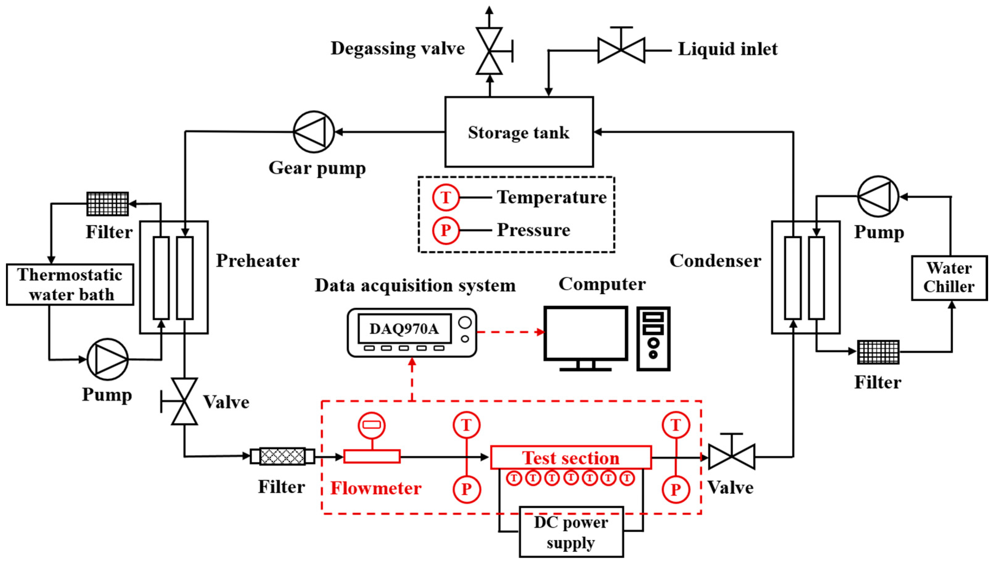
The schematic diagram of the experimental flow loop is provided in Figure 1, and the picture of the real flow loop is provided in Figure 2. The whole flow loop can be divided into the liquid circulation system, heating system, and data acquisition system. The circulation system was composed of the following instruments: a stainless-steel liquid storage tank, an external gear pump (Orient Pump Valve: MG-204XK, Nanjing, China), two plate heat exchangers working as the preheater and condenser (Wuxi LENMAN Heat Exchange Equipment: BK14A-32MFH, Wuxi, China), several ball valves (Keihin: SSPD, Yokohama, Japan), a liquid filter (Swagelok: SS-4F-90, Solon, OH, USA), a vortex street flowmeter (FIMETER: LWGY-10C, Hefei, China), the test section, a water chiller (ChangLiu Science Instrument: LX-5000, Beijing, China), and a thermostatic water bath (ShunMaTech: DC-2030, Nanjing, China). Additionally, 316 stainless steel tubes were used to connect the instruments. DI water was first infused into the storage tank and went through the preheater driven by the gear pump; the preheater was then connected to the thermostatic water bath to obtain a constant inlet liquid setting temperature. The flow rates were recorded via the flowmeter, and the impurities in the fluid were removed via the prepositive filter. After being heated in the test section, the DI water went through the condenser which connected to a water chiller to get cooled and was then returned to the storage tank; two valves were set on the storage tank to enable the inflow of liquid and extra gas discharge. As indicated in the figures, all tubes and heat exchangers were wrapped with insulated cotton to weaken the influence of the indoor environment on the flow loop. The heating system was composed of the DC power supply (ANS Power Supply: JP230100D, Wuxi, China) and the heaters inserted inside the test section. The data acquisition system included two pressure sensors (Omega: PX119-100AI, East Hartford, CT, USA) at inlet and outlet positions, two temperature sensors (KAIPUSEN: K-type WRNT-01, Xinghua, China) at inlet and outlet positions, seven thermocouples (Omega: KMTSS-020, East Hartford, CT, USA) arranged in the test section, a data collector (Keysight Technologies: DAQ970A, Santa Rosa, CA, USA), and a computer. All data were recorded by the data collector and finally gathered to the computer for further data reduction.
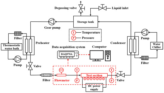
Figure 1.
Schematic diagram of experimental flow loop.

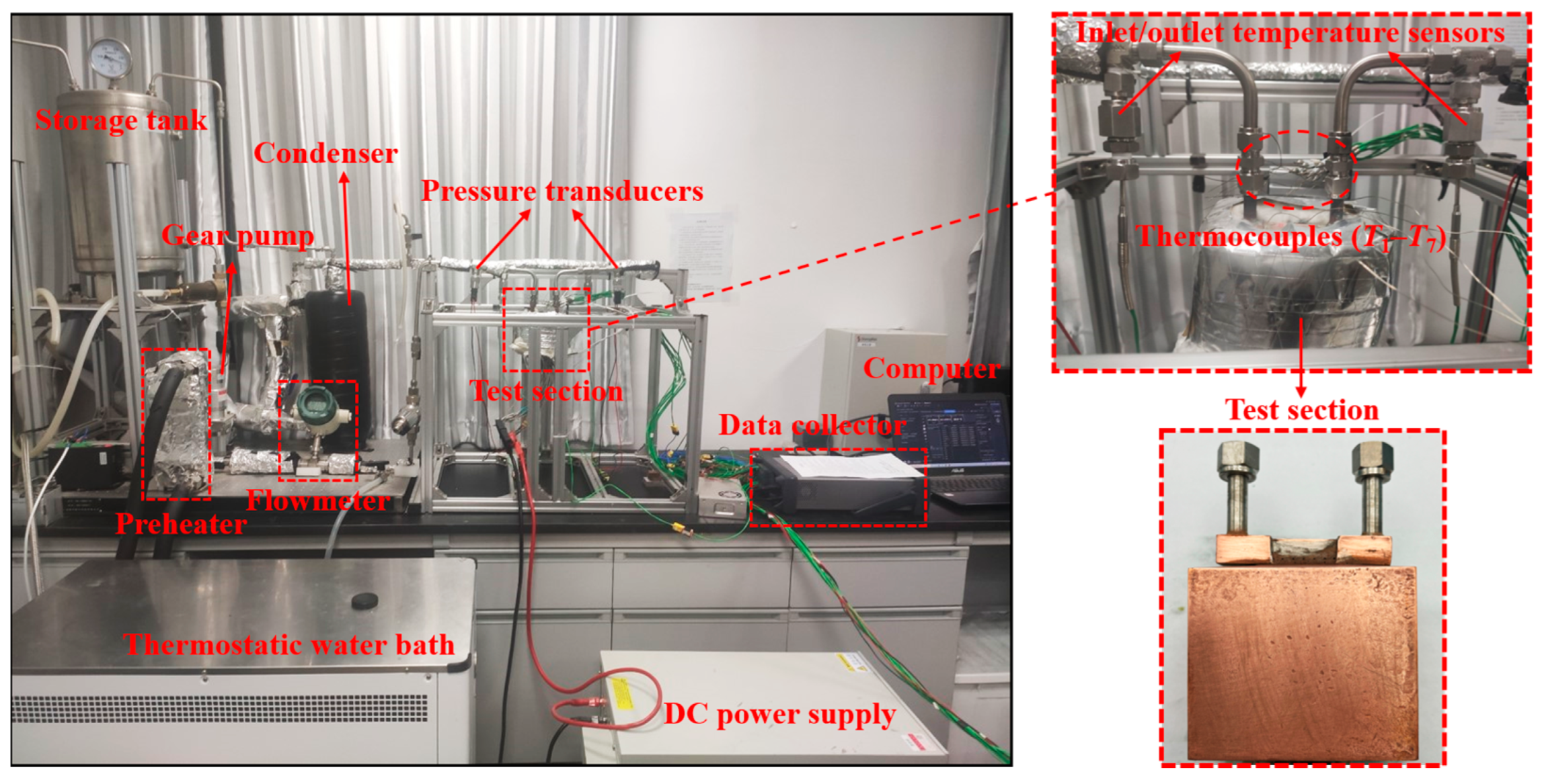
Figure 2.
Images of real experimental flow loop.
2.2. Introduction of Test Section
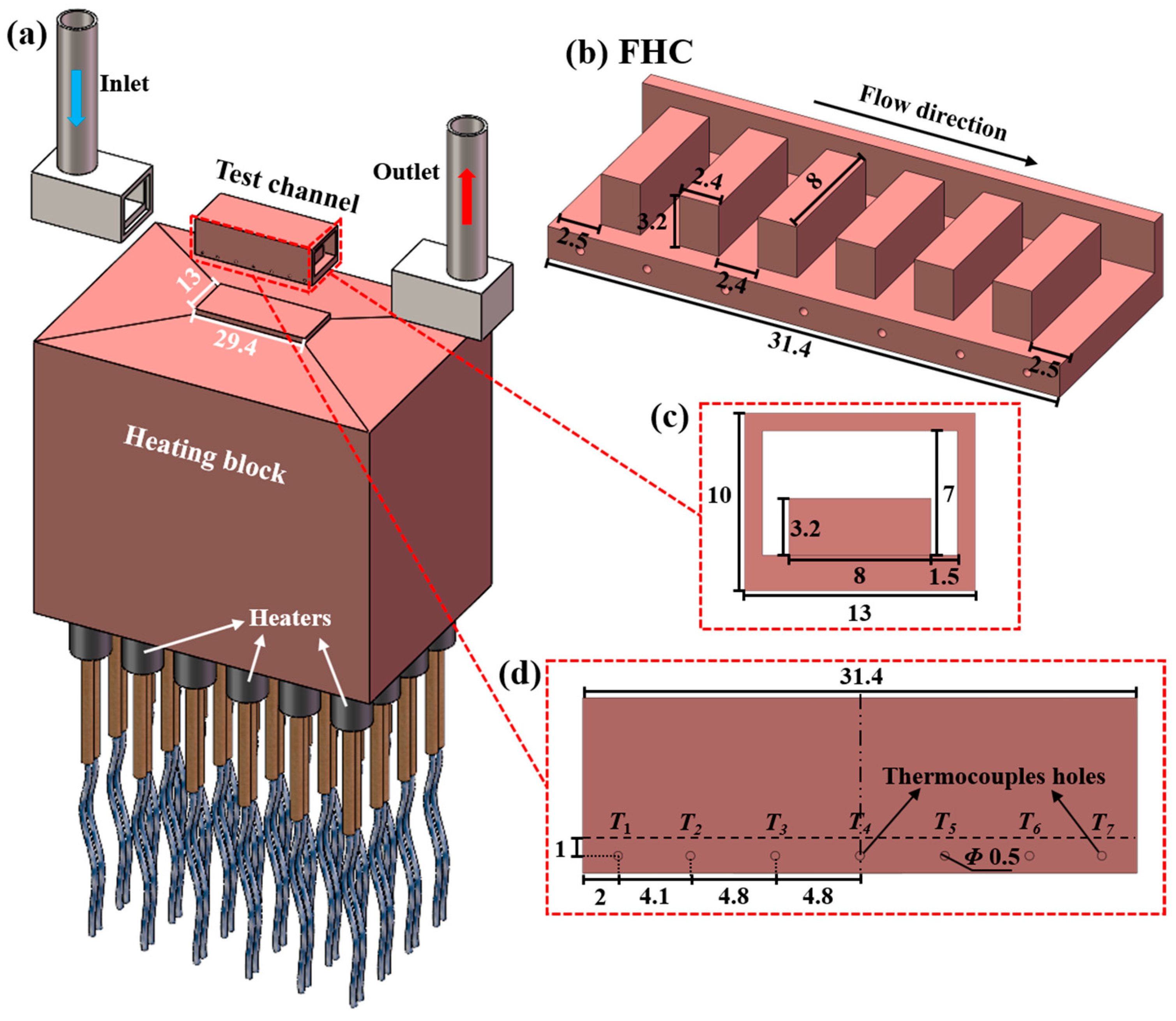
The diagrams of the experimental test section with the FHC as an example are pictured in Figure 3, and the geometric dimensions are labeled as well. As illustrated in Figure 3a, the test section was composed of the test channel, heating block, and liquid inlet/outlet chambers. All test channels (FHC, LMHC, and TMHC) and the heating block were made of CuCrZr, and these two parts were processed as a whole to decrease the interface thermal resistance. Moreover, 24 cartridge heaters which connected to the DC power supply were inserted into the heating block to provide heating power to the channel. The inlet and outlet chambers were made of stainless steel and were welded (by using the method of vacuum brazing) on both sides of the channel. Each test channel (FHC, LMHC, and TMHC) was independently welded with the corresponding inlet and outlet chambers. Note that the test section was covered with mica plates and insulated cotton to reduce the heat loss to the environment during the process of the experiments. The heating area was 13 × 29.4 mm2 as noted in the figure. As shown in Figure 3b,c, the whole channel was 31.4 mm in length, 11 mm in width, and 7 mm in height; six transverse-placed rectangular fins (length of 8 mm, width of 2.4 mm, and height of 3.2 mm) were arranged in the channel with an interval of 2.4 mm; the distances between the first fin to the inlet chamber and the last fin to the outlet chamber were both 2.5 mm. The width of the side channels between the fins and the sidewalls was 1.5 mm. Figure 3d illustrates the side view of the channel along with seven thermocouples holes arrangement (T1–T7). The diameter of the thermocouples holes was 0.5 mm, which were formed by using micro milling technology. Moreover, the distance between the holes and the bottom of the channel was 1 mm, and all holes were drilled to reach the central plane of the channel along with the flow direction. The distance between the first thermocouple (T1) to the inlet chamber was 2 mm, the distance between T2 and T3 was 4.1 mm, and the interval for T3, T4, and T5 was 4.8 mm; the arrangement of T5–T7 was symmetrical with T1–T3.
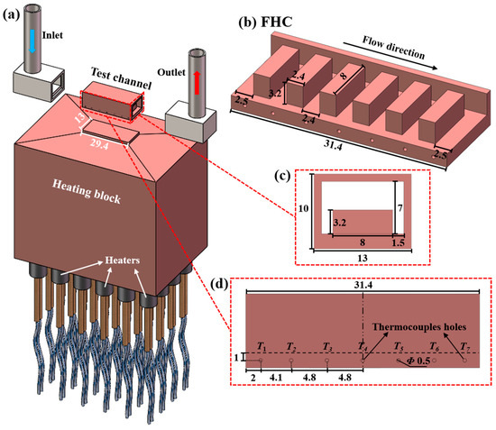
Figure 3.
Diagrams of test section (take FHC for an example): (a) exploded view of the whole test section, (b) cutaway view of the FHC, (c) cross-section view of the FHC, (d) side view along with thermocouple holes arrangement of the FHC; the units of the dimensions were in millimeter (mm).
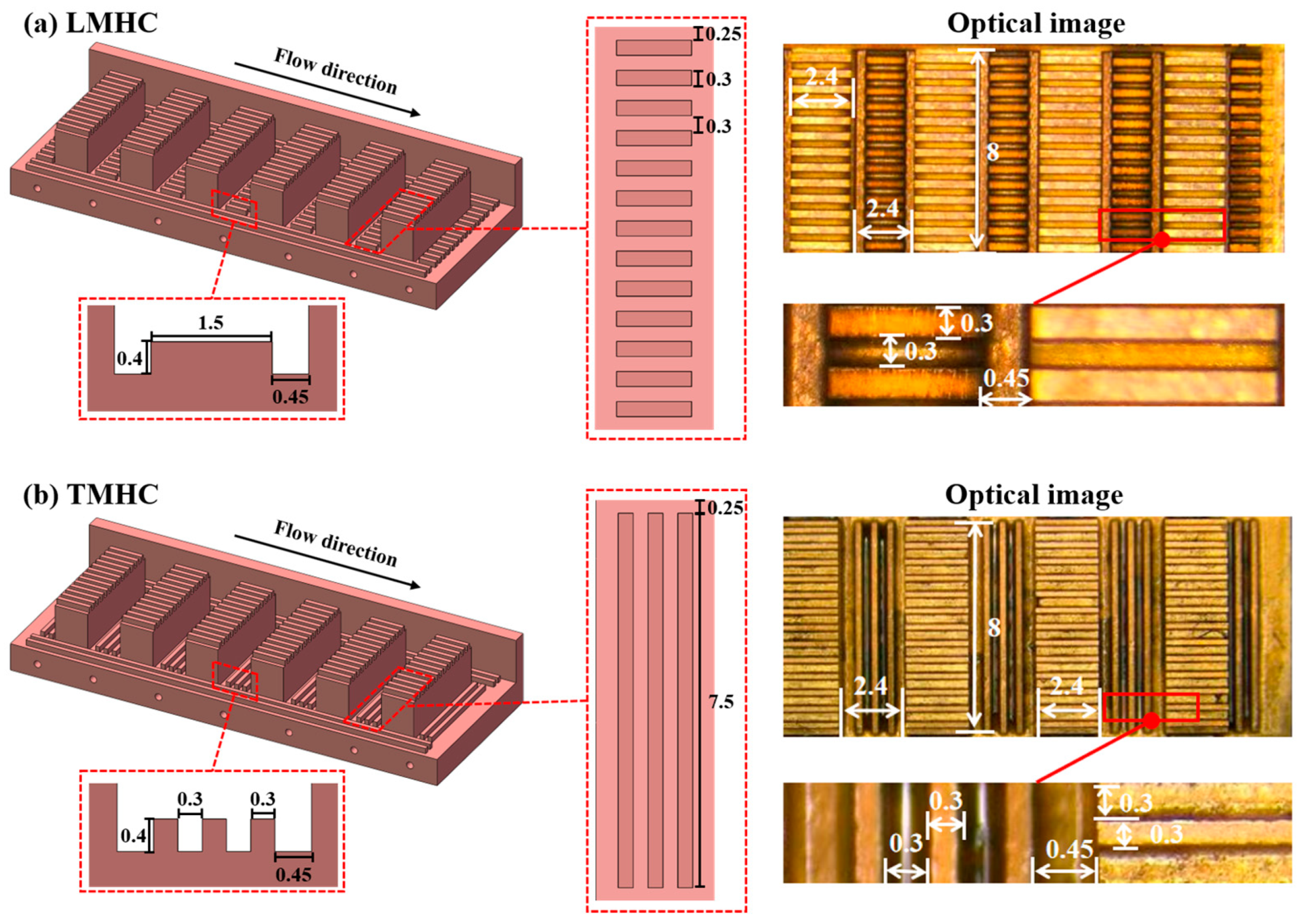
The diagrams and optical images of the LMHC and TMHC were, respectively, provided in Figure 4a,b. For both the LMHC and TMHC, 12 microchannels (width of 0.3 mm, length of 2.4 mm, and height of 0.4 mm) were symmetrically fabricated on the top of each rectangular fin along the flow direction with an interval of 0.3 mm; in addition, 3 microchannels (width of 0.3 mm, length of 29.4 mm, and height of 0.4 mm) were formed on each side channel along the flow direction with an interval of 0.3 mm. For LMHC, 12 longitudinal microchannels (width of 0.3 mm, length of 1.5 mm, height of 0.4 mm, and interval of 0.3 mm) were integrated between the fins, and the distance between both ends of the microchannel to the neighboring fins was 0.45 mm. For the TMHC, 4 transverse microchannels (width of 0.3 mm for the two in the middle, width of 0.45 mm for the two on both sides, length of 7.5 mm, height of 0.4 mm, and interval of 0.3 mm) were integrated between the fins. All microchannels were processed via micro milling technology, and they were well manufactured which can is indicated in the optical images. Note that the arrangement of inlet/outlet area, heating area, overall channel length/width, and locations of thermocouple holes of the LMHC and TMHC were exactly the same with the FHC for easier comparison.
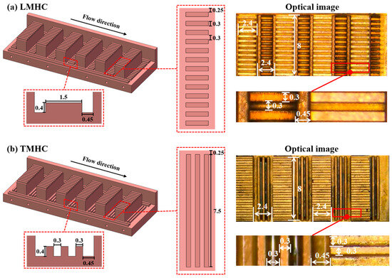
Figure 4.
Diagrams and optical images of the (a) LMHC and (b) TMHC; the units of the dimensions were in millimeter (mm).
2.3. Experimental Procedures
Prior to the experiments, all pressure sensors, temperature sensors, thermocouples and flowmeter had been calibrated; air tight tests were performed on all test sections and the equipment in the flow loop to ensure reliable operation of the loop under high temperature and pressure conditions; the parallel resistance of the cartridge heaters was checked to avoid short circuit caused by improper connection; and the DI water was boiled for 1 h before infusing in to the storage tank to eliminate the effects of insoluble gas. The water thermostatic bath and the water chiller were turned on to the set temperature (20 °C) to obtain a constant inlet temperature for the test section, and the gear pump was initiated to reach the setting for volume flow rates (0.033, 0.05, and 0.067 kg/s in this work) by adjusting the electronic controller. After the inlet temperature and volume flow rate were settled, the DC power supply was activated and adjusted by regulating the input voltages and corresponding currents to provide heating energy, and the heating energy was added up stepwise at each working condition. All temperature and pressure data were recorded for 300 s with a recording interval of 1 s after the steady state was achieved at certain working conditions, which was denoted as the maximum values of all temperature readings fluctuating within 0.5 °C and the pressure readings fluctuating within 0.5 kPa for 20 min; and the average values of the recorded data were used as the valid values for further data reduction. The flow loop was kept running for 1 h after the experiments to cool the channels. Note that the experiments on the FHC, LMHC, and TMHC were mutually independent.
2.4. Data Reduction
Total input heating power (Qinput) provided via the DC power supply was expressed as follows:
where U and I were the provided voltage and current of the power supply. To calculate the effective heating power absorbed by the channels, the heat loss of the test section, which was considered to be a combination of heat conduction, convection, and radiation loss to the ambient environment, needed to be estimated. The heat loss during single-phase flow was easy to calculate; however, the heat loss during two-phase flow was more difficult due to the complexity of the two-phase region. In this work, a commonly used method named the heat transfer ratio (r) [28,29,30] was utilized to estimate the heat loss and heat transfer efficiently during two-phase flow by referring to the heat loss and heat transfer in the single-phase region at certain working conditions. The effective heat absorbed by the DI water during single-phase flow (Qeff,s) can be calculated with the energy conservation equation:
where M is the mass flow rate, Cp is the specific heat, and Toutlet and Tinlet are the outlet and inlet temperatures of the test section. Thus, the heat transfer ratio during single-phase flow (r) can be acquired as follows:
where the subscript “s” indicates the single-phase state. Thereafter, the effective heating power adsorbed via the DI water during two-phase region (Qeff,t) was estimated using the obtained heat transfer ratio:
where the subscript “t” indicates the two-phase state.
The effective heat flux (qeff) was calculated according to the heating area (Ah) as illustrated in Figure 3, i.e., 29.4 × 13 mm2, and the effective absorbing power (Qeff) was calculated as follows:
The bottom wall temperatures of the channels (Tw,i, i = 1–7) at the corresponding positions of the thermocouples can be calculated via the one-dimensional thermal conductivity formula:
in which Ti (i = 1–7) are the reading temperatures of the thermocouples as indicated in Figure 3, λc is the thermal conductivity of CuCrZr, which is considered to vary with the temperatures, and x is denoted as the distance between the thermocouple holes to the bottom of the channel, i.e., 1 mm. Then, the average temperature of the bottom of the channel (Tw,ave) can be obtained as the average value of Tw,1–Tw,7 due to the symmetric arrangement of the thermocouples, which has been widely applied in previous studies [31,32,33]:
And the average liquid temperature (Tf,ave) can be acquired via the mean value of inlet and outlet temperatures:
Therefore, the overall heat transfer coefficient (h) can be obtained via the average wall temperature, average liquid temperature, and effective heat flux as follows [11,22]:
The pressure drop (∆P) of the channel can be calculated via the difference between the inlet (Pinlet) and outlet pressure (Poutlet) readings:
Uncertainty analysis was essential to experimental tests. In this work, the measured uncertainties were provided by the manufacturers and the calculated uncertainties were obtained via the uncertainty calculation method [34], which can be expressed as follows:
where g represents a calculated parameter, ai refers to a measured parameter, and R denotes the corresponding uncertainty of it. The maximum measured and calculated uncertainties are listed in Table 2.
Table 2.
Maximum uncertainties of various parameters.
3. Experimental Results and Discussion
3.1. Wall Temperatures
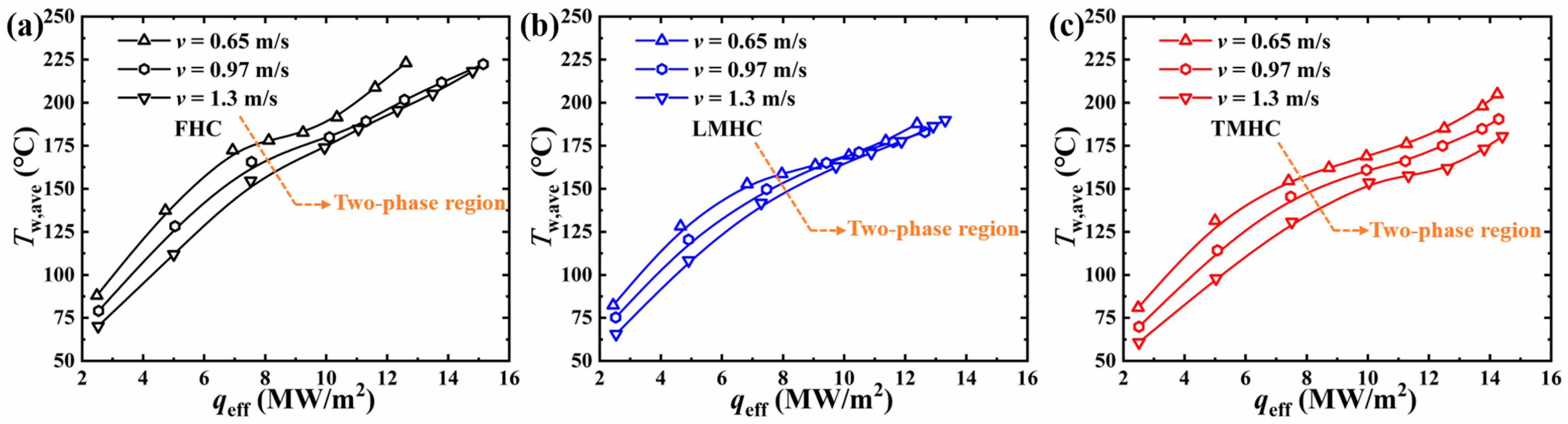
The variation in average bottom wall temperatures (Tw,ave) for the FHC, LMHC, and TMHC versus the effective heat flux (qeff) at various flow velocities were plotted in Figure 5. For all curves, it can be observed that Tw,ave obtained a linear increase at low heat flux, which indicated that the flow was in the single-phase region and the heat transfer process was solely dominated by liquid–solid convection [35]. The slopes of the curves decreased with further increase in the heat flux which indicated the initiation of nucleate boiling, and the flow transitioned to the two-phase region [31]. In this stage, the temperature rise per unit heat flux was smaller since the absorption of latent heat participated in the heat transfer process. On the other hand, the Tw,ave values for the FHC were generally higher than those of the LMHC and TMHC, which demonstrates that the integration of the microchannels of the LMHC and TMHC was conducive to heat dissipation with a larger solid–liquid contact area. The Tw,ave values for the LMHC and TMHC were comparable at low liquid velocity (v = 0.65 m/s) as shown in Figure 5a, indicating the heat dissipating capacity was insensitive to the configuration of the integrated microchannels at low flow velocity. However, the Tw,ave values for the TMHC were obviously lower than for the LMHC at higher liquid velocity (v = 0.97 and 1.3 m/s), which indicated a greater heat transfer coefficient for the TMHC at higher flow speed (detailed analysis of heat transfer coefficients will be discussed in Section 3.2). It was noticed that the Tw,ave of the FHC obtained an obvious upward trend at high heat flux (Figure 5a, qeff > 10.35 MW/m2) at v = 0.65 m/s which indicated the start of heat transfer deterioration [36]; under the low flow velocity condition, however, this kind of trend was not observed for the curves of the LMHC and TMHC.
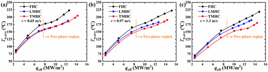
Figure 5.
Average bottom wall temperatures (Tw,ave) of the FHC, LMHC, and TMHC against effective heat flux (qeff) at various flow velocities: (a) v = 0.65 m/s, (b) v = 0.97 m/s, and (c) v = 1.3 m/s.
The variation in Tw,ave values in the same channels (FHC, LMHC, and TMHC, respectively) versus qeff at various flow velocities are plotted in Figure 6. It was shown that the wall temperatures uniformly decreased with the increase in liquid velocity at the same heat flux in the single-phase region for the FHC, LMHC, and TMHC due to the reduction in thermal boundary layer thickness at higher liquid speeds [29,37]. As for the two-phase flow region, for the FHC, as shown in Figure 6a, a relatively large increase in Tw,ave values, which indicated the initiation of heat transfer deterioration, was observed at high heat flux with v = 0.65 m/s as mentioned above. The Tw,ave values for the LMHC were comparable in the two-phase region at different flow velocities as shown in Figure 6b, which indicates that the heat dissipating process was insensitive to the flow velocity, the block effect of the branch flow from the mainflow to the middle of the fins (regular-sized hypervapotron fins) caused by the longitudinal arrangement of microchannels was responsible for it, and the local flow velocity between the fins was therefore hardly accelerated with the increase in mainflow velocity. Unlike the LMHC, the Tw,ave values for the TMHC normally decreased with the increase in flow velocity at the same heat flux in the two-phase region as illustrated in Figure 6c. As the transverse-arranged microchannels in the middle of the fins imparted little resistance, the branch flow and the flow velocity in these areas were obviously enhanced with the increase in mainflow velocity.
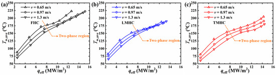
Figure 6.
Average bottom wall temperatures (Tw,ave) for the (a) FHC, (b) LMHC, and (c) TMHC against effective heat flux (qeff) at various flow velocities.
3.2. Heat Transfer Coefficient
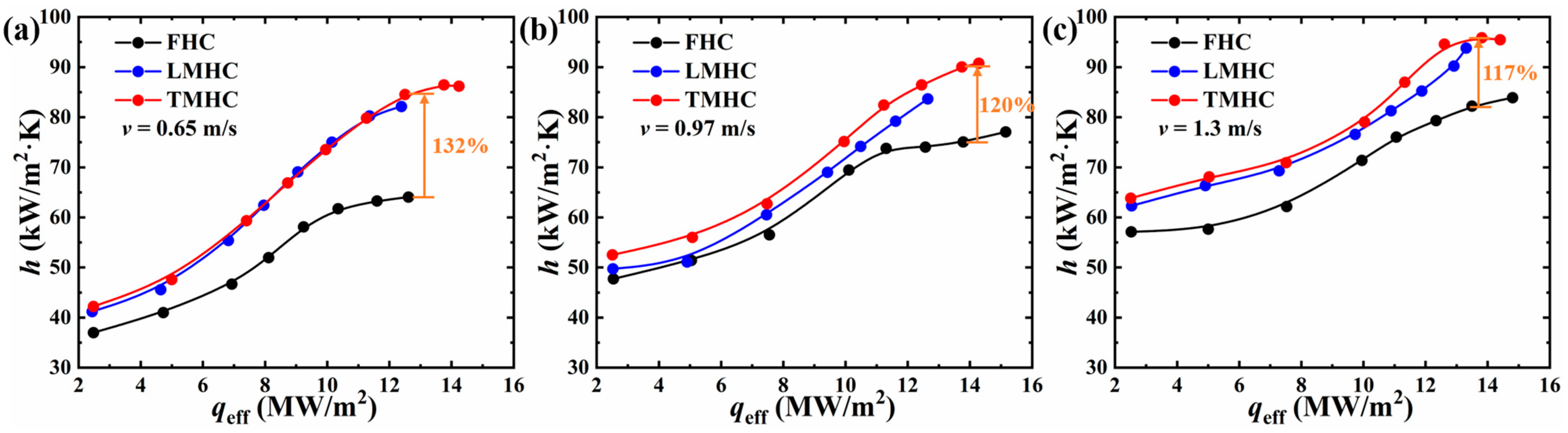
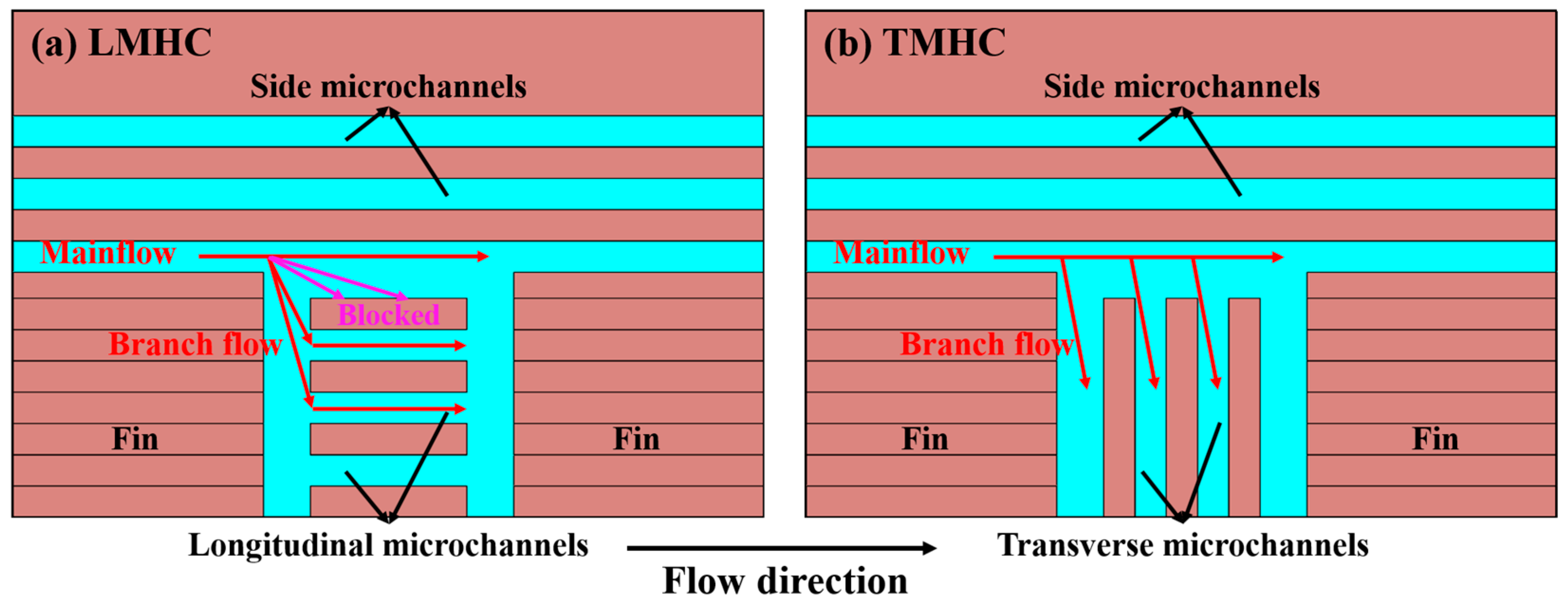
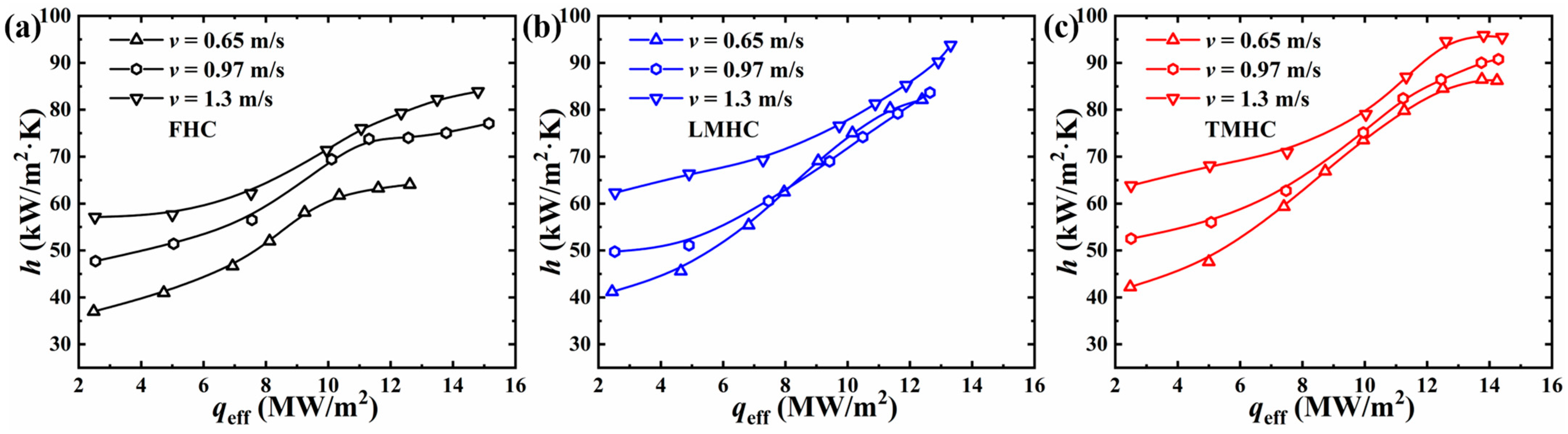
The heat transfer coefficients (h) for the FHC, LMHC, and TMHC versus the effective heat flux (qeff) at various flow velocities are plotted in Figure 7. It can be observed that all curves were relatively flat at the initiation stage as the heat transfer process was merely managed via single-phase convection, and the h increased more greatly with the addition of the effective heat flux since the heat transfer was conjointly dominated by the convection and phase-change heat transfer [30,38]. Moreover, the h the LMHC and TMHC outperformed that of the FHC under all working conditions which was ascribed to the expanded heat transfer area of the integrated microchannels. As shown in Figure 7a, the h curves for the LMHC and TMHC were close which denoted the placement of embed microchannels’ direction had little effect on the heat transfer at low flow velocity, i.e., as illustrated in Figure 8, the block effect to the branch flow of the longitudinal microchannels in the LMHC was inconspicuous at low flow velocity. However, the h for the TMHC was generally greater than that of the LMHC at higher liquid velocities (v = 0.97 and 1.3 m/s in Figure 7b,c), as the block effect to the branch flow of the LMHC was enlarged with the increase in liquid velocity, and the flow speed in microchannels at the bottom surface was therefore reduced. Thus, the convection of LMHC was weakened as well as the ability for liquid supplement, and the departure rates of nucleated bubbles/vapors were surpassed which led to further deterioration in heat transfer as stated in previous studies [13,15]. Regarding the TMHC, the transverse-arranged microchannels were conducive to the introduction of the branch flow to the microchannels which enhanced the convection effect and the liquid rewetting capability. Hence, the TMHC yielded the highest heat transfer coefficients for all conditions, and it was maximumly improved by 132%, 120%, and 117% compared to the traditional FHC at the flow velocities of 0.65, 0.97, and 1.3 m/s, respectively.
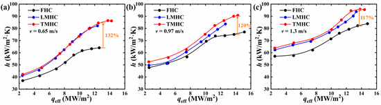
Figure 7.
Heat transfer coefficients (h) for FHC, LMHC, and TMHC against effective heat flux (qeff) at various flow velocities: (a) v = 0.65 m/s, (b) v = 0.97 m/s, and (c) v = 1.3 m/s.
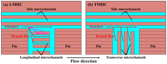
Figure 8.
Schematic diagrams of flow distribution of (a) LMHC and (b) TMHC at the bottom surface of the channel.
The variation in h for the same channels (FHC, LMHC, and TMHC, respectively) versus qeff at various flow velocities are plotted in Figure 9. For the FHC and TMHC, the h increased with the increase in flow velocity under the same heat flux. However, the h curves for the LMHC were comparable at medium-to-high heat flux at various v values because of the similar average wall temperatures as discussed in Section 3.1. It was noticed that the differences in h at various v values were diminished at medium heat flux for all three channels, which was due to the lower required heat flux for nucleate boiling at low flow velocity and the earlier participation of phase-change heat transfer procedure to the overall heat transfer process.
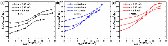
Figure 9.
Heat transfer coefficients (h) for (a) FHC, (b) LMHC, and (c) TMHC against effective heat flux (qeff) at various flow velocities.
3.3. Pressure Drop and Flow Instability
The pressure drop (∆P) for the FHC, LMHC, and TMHC versus the effective heat flux (qeff) at a liquid velocity of 1.3 m/s is plotted in Figure 10a. The pressure drop during the process of flow boiling mainly consists of two types of loss, the frictional loss caused by the liquid–solid friction and the vapor accelerating loss created by providing kinetic energy to newly generated bubbles/vapors [30,39]. It was indicated that the LMHC obtained the largest pressure drop due to the block effect of the longitudinal microchannels as mentioned above, which greatly increased both the frictional loss and vapor accelerating loss with more energy cost to supply water and depart bubbles/vapors in the middle of fins. The FHC and TMHC yielded comparable pressure drops which demonstrated that the transverse embedded microchannels had little effect on the frictional pressure loss compared to the traditional flat-type hypervapotron channel, and the generated bubbles/vapors were able to be discharged smoothly. The oscillation of pressure drops at high heat flux demonstrated that the flow pattern switched to two-phase flow; the sharp increase in pressure drop in the TMHC at qeff > 13.8 MW/m2 indicated fully developed flow boiling, and the dramatic increase in the vapor acceleration pressure loss was responsible for this surge. Moreover, the transient fluctuations in pressure drop for the FHC, LMHC, and TMHC at v = 1.3 m/s at qeff ~ 13.5 MW/m2 within 60 s are drawn in Figure 10b; the standard deviations (σ) for each group of data, which were commonly used to characterize the dispersion degree [38,40], have been calculated and noted in the figure as well. It was shown that the LMHC obtained both the greatest amplitude (94.1 kPa) and standard deviation (22.535) of the transient pressure drop, i.e., the greatest two-phase flow instability, which was subject to the weak liquid replenishment ability during the violent boiling process due to the block effect. The amplitude (65.1 kPa) and standard deviation (16.663) of the pressure drop in the TMHC was slightly lower than the LMHC which indicated better stability. Moreover, the FHC had the smallest amplitude (27.3 kPa) and standard deviation (5.928) of pressure drop at the same heat flux due to the fact that the FHC obtained a limited heat transfer area and relatively modest flow boiling process compared to the LMHC and TMHC.
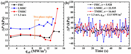
Figure 10.
(a) Average pressure drop (∆P) for FHC, LMHC, and TMHC against effective heat flux (qeff) at v = 1.3 m/s and (b) transient fluctuation of pressure drop of FHC, LMHC, and TMHC at v = 1.3 m/s with effective heat flux of 13.5 MW/m2.
3.4. Comprehensive Performance
The investigation of comprehensive performance considering both the heat transfer capacity and the corresponding energy consumption was of significant importance. In this work, an evaluation method named Figure of Merit (FOM) [41] was applied to evaluate the comprehensive performance of the LMHC and TMHC compared to the traditional flat-type hypervapotron channel, and the calculation formula is provided below:
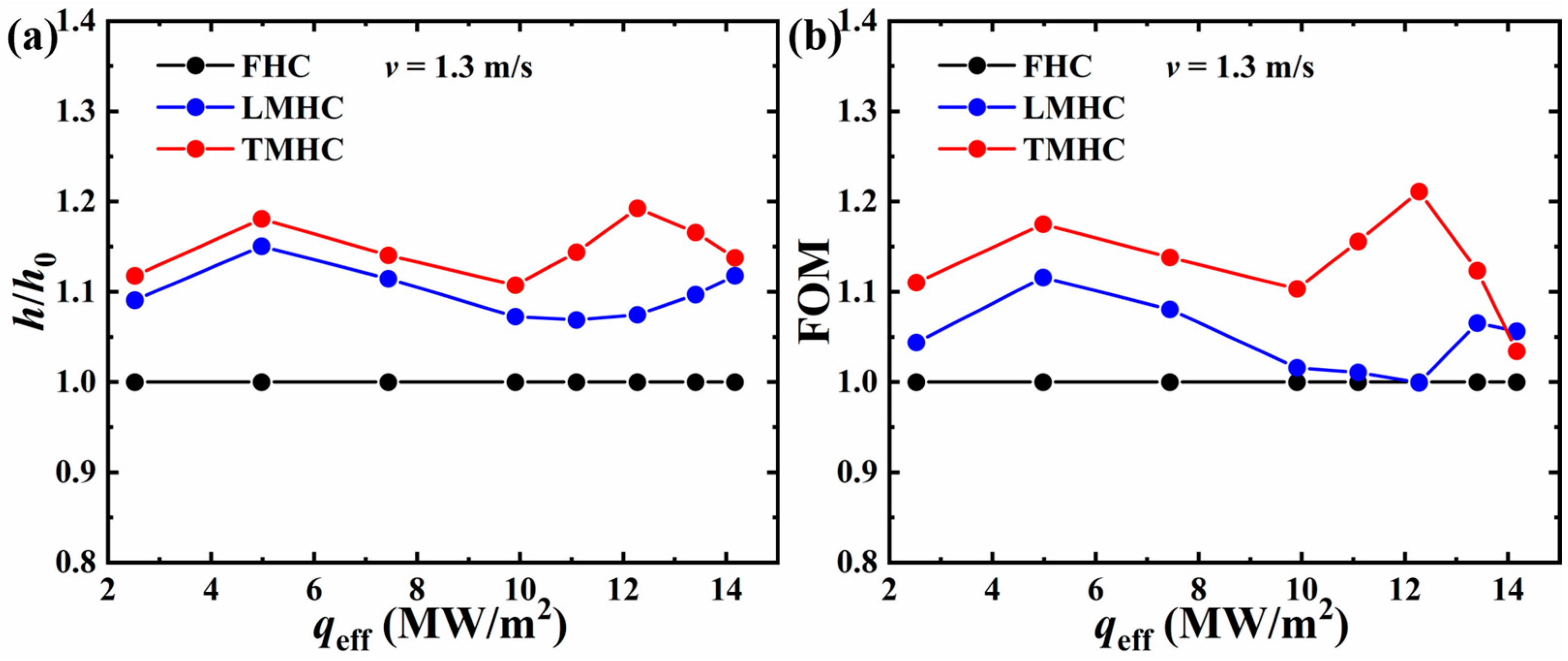
where h is the heat transfer coefficient of a certain channel, and Qp is the pumping power; the subscript “0” represents the baseline, i.e., the data from the FHC in this work; ∆P is the pressure drop, and M is the mass flow rate. Accordingly, the curves of h/h0 and FOM at a liquid velocity of 1.3 m/s for the LMHC and TMHC are plotted in Figure 11. As illustrated in the figures, the h/h0 and FOM for the LMHC and TMHC were generally greater than for the FHC, and the TMHC yielded the highest FOM with an average value of 1.13 which indicated significant thermohydraulic performance compared to other two channels. The average value of FOM for the TMHC was 0.083 higher than that of the LMHC which was ascribed to the slight enhancement in the heat transfer coefficient caused by greater flow speed in microchannels and obvious pressure drop reduction which benefited from the little block effect for the TMHC compared to the LMHC. It was noted that the FOMs for the LMHC at qeff ≥ 10 MW/m2 were close to the baseline which was ascribed to the increased pressure drop during two-phase flow triggered by the block effect as mentioned in Section 3.3; however, the FOMs for the TMHC at 10 ≤ qeff ≤ 12.3 MW/m2 remained stable as the required heat flux to trigger flow boiling instability was higher and the pressure drop was yet to surge. Moreover, the sharp FOM decline for the TMHC at high heat flux was caused by the intense increase in the pressure drop during fully developed flow boiling as described in Figure 10a.

Figure 11.
(a) h/h0 and (b) FOM of the LMHC and TMHC with the FHC considered as the baseline.
4. Conclusions
In this work, symmetric CuCrZr-based longitudinal microchannels integrated with a hypervapotron channel (LMHC) and transverse microchannels integrated with a hypervapotron channel (TMHC) were proposed and manufactured, subcooled flow boiling experiments were conducted with an inlet temperature of 20 °C at various flow velocities, and a traditional flat-type hypervapotron channel (FHC) was used for comparison. The thermohydraulic performance was thoroughly investigated and the main conclusions are listed as follows:
- The average bottom wall temperatures of the LMHC and TMHC were generally lower than FHC at the same effective heat flux in all conditions, TMHC obtained the lowest wall temperatures, and the temperatures of the LMHC were insensible to the flow velocities;
- The heat transfer coefficients of the LMHC and TMHC were greater than those of the FHC due to the expanded heat transfer area provided by the integrated microchannels; the TMHC yielded the greatest heat transfer coefficient (maximumly increased by 132%, 120%, and 117% at a liquid velocity of 0.65, 0.97, and 1.3 m/s compared to FHC) because the transverse arranged microchannels promoted the convection and liquid replenishment capability by introducing branch flow between fins. The heat transfer coefficients of the LMHC were insensible to the flow velocities due to the block effect of the longitudinal microchannels;
- The LMHC obtained the largest pressure drop on account of the increased frictional pressure loss caused by the block effect; the pressure drop for the FHC and TMHC were comparable at low-to-medium heat flux since the effect of the transverse microchannels on the frictional pressure loss was minimal. However, the pressure drop for the TMHC exhibited a sharp increase at high heat flux (qeff > 13.8 MW/m2) which indicated that the full development of flow boiling dramatically enlarged the vapor acceleration pressure loss;
- The TMHC generally obtained the highest Figures of Merit (FOM) with the FHC set as the baseline, which indicated the significant thermohydraulic performance of the TMHC and might bring critical insight to the structural design of hypervapotron devices.
Author Contributions
Conceptualization, X.C. and K.C.; methodology, X.M. and K.C.; software, X.M. and K.C.; validation, X.M. and Q.Z.; formal analysis, X.M., K.C. and Q.Z.; investigation, X.M., K.C., Q.Z. and X.C.; resources, X.C.; data curation, K.C. and X.C.; writing—original draft preparation, X.M. and Q.Z.; writing—review and editing, X.M., Q.Z. and X.C.; supervision, X.C. All authors have read and agreed to the published version of the manuscript.
Funding
This research was funded by the National Natural Science Foundation of China, grant number 52276071 and U2241252.
Data Availability Statement
Data are contained within the article.
Conflicts of Interest
The authors declare no conflicts of interest.
References
- Artsimovich, L. The Road to Controlled Nuclear Fusion. Nature 1972, 239, 18–22. [Google Scholar] [CrossRef]
- Sadik-Zada, E.R.; Gatto, A.; Weißnicht, Y. Back to the future: Revisiting the perspectives on nuclear fusion and juxtaposition to existing energy sources. Energy 2024, 290, 129150. [Google Scholar] [CrossRef]
- Motojima, O. The ITER project construction status. Nucl. Fusion 2015, 55, 104023. [Google Scholar] [CrossRef]
- Qin, S.; Zhao, S.; Cao, J.; Wang, Q.; Feng, X.; Chen, S. Reliability research of hypervapotron under electromagnetic load for CFETR divertor. Fusion Eng. Des. 2024, 202, 114422. [Google Scholar] [CrossRef]
- Peng, X.; Ye, M.; Song, Y.; Mao, X.; Chen, P.; Qian, X. Engineering conceptual design of CFETR divertor. Fusion Eng. Des. 2015, 98–99, 1380–1383. [Google Scholar] [CrossRef]
- Li, M.; You, J.-H. Interpretation of the deep cracking phenomenon of tungsten monoblock targets observed in high-heat-flux fatigue tests at 20 MW/m2. Fusion Eng. Des. 2015, 101, 1–8. [Google Scholar] [CrossRef]
- Zhao, B.; Musa, S.; Abdel-Khalik, S.; Yoda, M. Experimental and numerical studies of helium-cooled modular divertors with multiple jets. Fusion Eng. Des. 2018, 136, 67–71. [Google Scholar] [CrossRef]
- Rindt, P.; van den Eijnden, J.L.; Morgan, T.W.; Lopes Cardozo, N.J. Conceptual design of a liquid-metal divertor for the European DEMO. Fusion Eng. Des. 2021, 173, 112812. [Google Scholar] [CrossRef]
- Li, Q.; Zhao, S.X.; Sun, Z.X.; Xu, Y.; Li, B.; Wei, R.; Wang, W.J.; Qin, S.G.; Shi, Y.L.; Xie, C.Y.; et al. Development and application of W/Cu flat-type plasma facing components at ASIPP. Phys. Scr. 2017, T170, 014020. [Google Scholar] [CrossRef]
- Chen, X.; Qin, S.; Wang, Q.; Cao, J. Fatigue life prediction of hypervapotron for CFETR divertor. Fusion Eng. Des. 2022, 174, 112985. [Google Scholar] [CrossRef]
- Zhu, G.; Bi, Q.; Yan, J.; Wang, T.; Zhao, J. Heat transfer characteristics of subcooled water in a hypervapotron under high mass fluxes and high heat fluxes. Int. J. Heat Mass Transf. 2019, 129, 580–590. [Google Scholar] [CrossRef]
- Escourbiac, F.; Schlosser, J.; Merola, M.; Bobin Vastra, I. Experimental optimisation of a hypervapotron® concept for ITER plasma facing components. Fusion Eng. Des. 2003, 66–68, 301–304. [Google Scholar] [CrossRef]
- Youchison, D.L.; Ulrickson, M.A.; Bullock, J.H. Effects of Hypervapotron Geometry on Thermalhydraulic Performance. IEEE Trans. Plasma Sci. 2012, 40, 653–658. [Google Scholar] [CrossRef]
- Zhao, Y.; Zhang, M.; Hou, F.; Gao, T.; Chen, P. An experimental study of hypervapotron structure in external reactor vessel cooling. Nucl. Eng. Des. 2016, 303, 42–49. [Google Scholar] [CrossRef]
- Wu, Z.; Qian, X.; Peng, X.; Song, Y.; Song, W.; Song, F.; Liu, P. Modeling of subcooled flow boiling for hypervapotron in divertor of fusion reactor based on RPI model. Case Stud. Therm. Eng. 2023, 49, 103289. [Google Scholar] [CrossRef]
- Feng, S.; Peng, X.; Song, Y.; Liu, P.; Song, W.; Mao, X.; Qian, X.; Salman Khan, M. Development of continuous V-shaped structure for high heat flux components of flat-type divertor. Nucl. Mater. Energy 2023, 35, 101419. [Google Scholar] [CrossRef]
- Qi, L.; Shifeng, M.; Zhongwei, W.; Xufeng, L.; Minyou, Y. Study on the effect of fin structure on heat transfer performance of hypervapotron structure. Nucl. Fusion Plasma Phys. 2019, 39, 48–54. [Google Scholar] [CrossRef]
- Cao, J.; Qin, S.; Wang, Q.; Chen, X.; Feng, X. Reliability research of hypervapotron under steady-state thermal load. Fusion Eng. Des. 2022, 180, 113191. [Google Scholar] [CrossRef]
- Ezato, K.; Suzuki, S.; Sato, K.; Taniguchi, M.; Hanada, M.; Araki, M.; Akiba, M. Critical heat flux test on saw-toothed fin duct under one-sided heating conditions. Fusion Eng. Des. 2001, 56–57, 291–295. [Google Scholar] [CrossRef]
- Lim, J.H.; Park, M. Effect of Hypervapotron Fin Angle on Subcooled Flow Boiling Heat Transfer Performance Under One-Side High-Heat Load Condition. Fusion Sci. Technol. 2022, 78, 395–413. [Google Scholar] [CrossRef]
- Chen, Z.; Li, Q.; Peng, W.; Wei, R.; Wang, W.; Jiang, K.; Wang, J.; Pan, Z.; Xie, C.; Geng, X.; et al. Study of W/Cu flat-type mock-ups with novel hypervapotron cooling structure for CFETR divertor. Fusion Eng. Des. 2021, 172, 112919. [Google Scholar] [CrossRef]
- Chen, Z.; Li, Q.; Zhou, Z.; Wang, X.; Zhao, B.; Peng, W.; Du, F.; Wang, W.; Yang, Z.; Xu, Y.; et al. Experimental investigation on heat transfer characteristics of a novel hypervapotron channel for divertor target in nuclear fusion reactors. Nucl. Mater. Energy 2024, 39, 101651. [Google Scholar] [CrossRef]
- Erp, R.; Soleimanzadeh, R.; Nela, L.; Kampitsis, G.; Matioli, E. Co-designing electronics with microfluidics for more sustainable cooling. Nature 2020, 585, 211–216. [Google Scholar] [CrossRef]
- He, Z.; Yan, Y.; Zhang, Z. Thermal management and temperature uniformity enhancement of electronic devices by micro heat sinks: A review. Energy 2021, 216, 119223. [Google Scholar] [CrossRef]
- Singh, S.; Malik, A.; Mali, H.S. A critical review on single-phase thermo-hydraulic enhancement in geometrically modified microchannel devices. Appl. Therm. Eng. 2023, 235, 121729. [Google Scholar] [CrossRef]
- Tuckerman, D.B.; Pease, R.F.W. High-Performance Heat Sinking for VLSI. IEEE Electron Device Lett. 1981, 2, 126–129. [Google Scholar] [CrossRef]
- Lu, M.; Han, L.; Zhou, J.; Zhao, Q.; Li, Q.; Chen, X. Thermohydraulic and thermal fatigue characteristics of W/Cu flat-type microchannel mock-up for CFETR divertor. Appl. Therm. Eng. 2024, 238, 122079. [Google Scholar] [CrossRef]
- Wang, G.; Cheng, P.; Bergles, A.E. Effects of inlet/outlet configurations on flow boiling instability in parallel microchannels. Int. J. Heat Mass Transf. 2008, 51, 2267–2281. [Google Scholar] [CrossRef]
- Harirchian, T.; Garimella, S.V. Effects of channel dimension, heat flux, and mass flux on flow boiling regimes in microchannels. Int. J. Multiph. Flow 2009, 35, 349–362. [Google Scholar] [CrossRef]
- Yin, L.; Jiang, P.; Xu, R.; Hu, H.; Jia, L. Heat transfer and pressure drop characteristics of water flow boiling in open microchannels. Int. J. Heat Mass Transf. 2019, 137, 204–215. [Google Scholar] [CrossRef]
- Zhou, J.; Chen, X.; Zhao, Q.; Lu, M.; Hu, D.; Li, Q. Flow thermohydraulic characterization of hierarchical-manifold microchannel heat sink with uniform flow distribution. Appl. Therm. Eng. 2021, 198, 117510. [Google Scholar] [CrossRef]
- Li, P.; Guo, D.; Huang, X. Heat transfer enhancement, entropy generation and temperature uniformity analyses of shark-skin bionic modified microchannel heat sink. Int. J. Heat Mass Transf. 2020, 146, 118846. [Google Scholar] [CrossRef]
- Li, W.; Chen, Z.; Li, J.; Sheng, K.; Zhu, J. Subcooled flow boiling on hydrophilic and super-hydrophilic surfaces in microchannel under different orientations. Int. J. Heat Mass Transf. 2019, 129, 635–649. [Google Scholar] [CrossRef]
- Moffat, R.J. Describing the uncertainties in experimental results. Exp. Therm. Fluid Sci. 1988, 1, 3–17. [Google Scholar] [CrossRef]
- Deng, D.; Zeng, L.; Sun, W.; Pi, G.; Yang, Y. Experimental study of flow boiling performance of open-ring pin fin microchannels. Int. J. Heat Mass Transf. 2021, 167, 120829. [Google Scholar] [CrossRef]
- Cheng, X.; Wu, H. Improved flow boiling performance in high-aspect-ratio interconnected microchannels. Int. J. Heat Mass Transf. 2021, 165, 120627. [Google Scholar] [CrossRef]
- Li, Y.; Wu, H.; Yao, Y. Enhanced flow boiling heat transfer and suppressed boiling instability in counter-flow stepped microchannels. Int. J. Heat Mass Transf. 2022, 194, 123025. [Google Scholar] [CrossRef]
- Deng, D.; Chen, L.; Wan, W.; Fu, T.; Huang, X. Flow boiling performance in pin fin- interconnected reentrant microchannels heat sink in different operational conditions. Appl. Therm. Eng. 2019, 150, 1260–1272. [Google Scholar] [CrossRef]
- Alam, T.; Lee, P.S.; Yap, C.R.; Jin, L. Experimental investigation of local flow boiling heat transfer and pressure drop characteristics in microgap channel. Int. J. Multiph. Flow 2012, 42, 164–174. [Google Scholar] [CrossRef]
- Deng, D.; Wan, W.; Qin, Y.; Zhang, J.; Chu, X. Flow boiling enhancement of structured microchannels with micro pin fins. Int. J. Heat Mass Transf. 2017, 105, 338–349. [Google Scholar] [CrossRef]
- Ho, C.J.; Chang, P.-C.; Yan, W.-M.; Amani, P. Efficacy of divergent minichannels on cooling performance of heat sinks with water-based MEPCM suspensions. Int. J. Therm. Sci. 2018, 130, 333–346. [Google Scholar] [CrossRef]


Disclaimer/Publisher’s Note: The statements, opinions and data contained in all publications are solely those of the individual author(s) and contributor(s) and not of MDPI and/or the editor(s). MDPI and/or the editor(s) disclaim responsibility for any injury to people or property resulting from any ideas, methods, instructions or products referred to in the content. |
© 2024 by the authors. Licensee MDPI, Basel, Switzerland. This article is an open access article distributed under the terms and conditions of the Creative Commons Attribution (CC BY) license (https://creativecommons.org/licenses/by/4.0/).