Article

Effect of Laying Angle on the Stress Distribution and Stiffness Degradation of Symmetrically Cracked Laminates

1
School of Mechanical and Electronic Engineering, Jingdezhen Ceramic University, Jingdezhen 333403, China
2
School of Mechanical Engineering, Tsinghua University, Beijing 100084, China
*
Author to whom correspondence should be addressed.
Symmetry 2025, 17(4), 495; https://doi.org/10.3390/sym17040495
Submission received: 27 January 2025 / Revised: 5 March 2025 / Accepted: 20 March 2025 / Published: 25 March 2025
(This article belongs to the Special Issue Symmetry in Mechanical Engineering: Properties and Applications)

Abstract

:
In this paper, the effects of laying angle on the stress distribution and stiffness degradation of glass epoxy laminates with symmetrical cracks are systematically studied by variational analysis and numerical simulation. Based on the principle of minimum complementary energy, the control equation was established and solved using MATLAB programming. The stress field and stiffness attenuation characteristics of 90°-layer crack density (CD = 0.5 cr/mm) and laminates with different angles [ θ m / 90 n ] s were analyzed. The results show that the crack significantly aggravates the stress concentration effect, and when the laying angle exceeds 45°, the crack growth rate and stiffness degradation rate are significantly improved. Specifically, when the laying angle is 30° and L1/t1 = 50, the stiffness degradation rate (Ex/Ex0) of the laminates only decreases to 0.987, while when the laying angle increases to 60° and L1/t1 = 3, the stiffness degradation rate suddenly decreases to 0.754 under the same conditions, indicating that small-angle laying (<45°) can effectively alleviate local stress concentration and delay stiffness degradation. By comparing the experimental data of existing references, the model error is verified to be less than 1%, and the reliability of the method is confirmed. It is further proposed that in the design of symmetrical laminated plates, the crack propagation resistance can be significantly optimized by controlling the laying angle of the main bearing layer in the range of 30°~45°, which provides a quantitative basis for crack suppression and structural life improvement in engineering.

1. Introduction

Composite laminates are widely used in aerospace, automotive manufacturing, marine engineering, and other high-performance structures due to their light weight, high strength, flexible design, and excellent corrosion resistance. As a typical composite material [1], glass epoxy is composed of glass fiber and epoxy matrix. Glass fiber has the characteristics of high strength and high modulus, which endows the composite with good mechanical properties and enables it to withstand large loads. The epoxy has excellent adhesion and chemical resistance, which can effectively bond the glass fibers together, ensuring the integrity of the composite material and protecting the fibers from the external environment. The material structure of this paper is shown in Figure 1. However, complex environments and external load conditions will lead to cracks, delamination, and other damage to the laminated plate, which will not only change the stress distribution of the composite material, but also significantly reduce its structural stiffness and bearing capacity, thus threatening the safety and reliability of engineering structures. In order to ensure the long-term stability of laminates [2] under actual working conditions, it is particularly important to study the influence of cracks on the mechanical properties of laminates.
In recent years, many researchers have carried out research on the mechanical behavior and stiffness degradation of laminates with cracks. Through variational stress analysis and experimental verification, Fikry et al. revealed [3] the influence of matrix cracks on the stiffness degradation of fiber-reinforced polymer (FRP) laminates with different off-axis angles. Ramezani et al. [4] demonstrated that the addition of carbon nanofibers (CNFs) can effectively inhibit crack propagation in the matrix of fiber polymer composites and significantly reduce the crack density and stiffness degradation. Ghadami [5] proposed a new anisotropic nonlinear multi-scale damage model based on the TALREJA method. Experimental verification showed that the model is significantly better than the existing theories for stress–strain prediction and reference state optimization. Chaupa [6] used five different convolutional neural network (CNN) models with transfer learning techniques to discriminate whether randomly oriented chopped glass fiber composite laminates were damaged or not. Fakoor [7] predicted the critical angle between fiber and crack directions in orthotropic materials through stress series expansion and numerical methods, combined with experimental validation, thereby establishing a theoretical foundation for preventing stiffness degradation and catastrophic failure. Farrokhabadi [8] calculated the changes in the mechanical properties of symmetric laminates in the presence of matrix cracks by considering the equivalent damage layer and using the relationships of classical laminate theory (CLT). Mohammadi [9] used the variational method to simulate the damage state and verified the propagation of matrix crack with experiments. Pakdel et al. [10] established an energy-based criterion for predicting the distribution pattern of matrix cracks in laminates under uniaxial tensile loading with competitive damage modes. Qi, Wenxuan et al.’s research [11] is based on the continuum damage mechanics (CDM) theory; the proposed model is effective and reliable in predicting the occurrence and evolution of matrix cracks and the corresponding stiffness degradation in composite laminates under fatigue loading. Rezaei Jafari [12] quantitatively predicted the dynamic association between stiffness degradation and strain energy release rate during crack propagation in a sub-matrix by developing an energy-based analytical model with a crack-closure technique. Kassapoglou et al. [13] proposed a model to accurately calculate the stress of the matrix crack layer under a combined strain state. Based on the energy density criterion, the predicted crack spacing is in good agreement with the test results. Yuan, Mingqing et al. [14] proposed a data-driven method to predict the stiffness degradation of cross-ply laminates with matrix cracking, which provides an efficient method for the optimization of damage and the mechanical properties of composites. Zhang et al. [15] proposed that the shear stress of laminates varies linearly within a 90° layer. Berthelot [16] argues that the relationship between the longitudinal displacement of the laminate and the transverse coordinate is quadratic within the 90° layer and that the scaling factor of this relationship is an exponential function of the transverse crack density. M. Kashtalyan et al. [17] proposed an improved two-dimensional shear lag analysis method. Relevant scholars have discussed the stiffness degradation for calculating the internal stress field of cracked laminates using the shear lag model and its modified model and the energy principle [18], and described the stiffness degradation [19,20,21] process. In subsequent studies, scholars have continuously explored and summarized the variational method [22,23], which is used to determine the stress field of cross-laminated plates with cracks [24,25] present in 90° layers under tensile and shear loads [26].
In this paper, the general expression of the stress component is obtained through the boundary conditions of the damage analysis element and the equilibrium differential equation, and the governing equation and supplementary equation are established using the variation in the minimum complementary energy principle. Programming calculations are undertaken with MATLAB2021. We calculate and analyze cracks under ideal conditions, calculating the normal stress distribution and the change in the stiffness degradation [27] of 90° laminated plates. By citing the models of other researchers and comparing the experimental results, the accuracy of this model is verified.

2. Mathematical Modeling and Theoretical Formulation

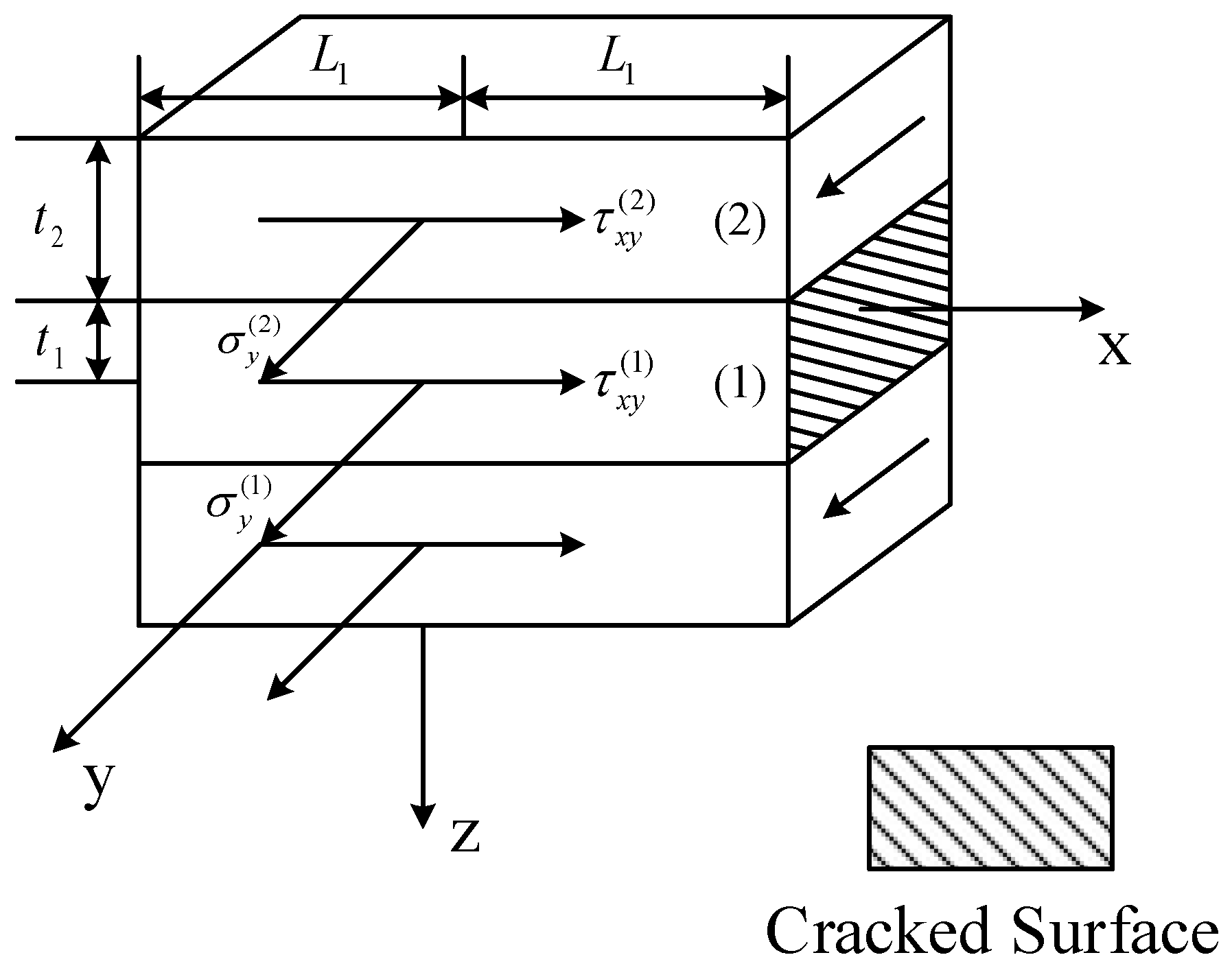
2.1. Analysis Unit Model

In symmetrical laminates [ θ m / 90 n ] s , the upper and lower θ layers have the same mechanical properties, while the middle 90° layer has different mechanical properties due to having different ply angles. Under the action of load, the transverse cracks in the 90° layer will be evenly distributed along the main direction until they penetrate the entire 90° layer of the laminate. Therefore, the cracks in the angle-ply symmetric laminate have periodicity in the main direction. Select the volume element RVE in the damaged area, as shown in Figure 2. t 1 = n t 0 and t 2 = m t 0 are the thickness of the 90° layer and the θ layer. Subscripts 1 and 2 represent the 90° layer and the θ layer, respectively. The distance between the two cracks is 2 L 1 . h = t 1 + t 2 . The laminate is laid in sequence from top to bottom at θ , 90°, and θ , and has upper and lower symmetry in the structure. Therefore, only the upper half of the volume element needs to be studied ( z 0 ) .

2.2. Boundary Conditions and Representations of the Stress Components

At the boundary x = ± L 1 , the tensile stress and shear stress of layers (1) and (2) meet the resultant force of
t 1 σ x ( 1 ) x = ± L 1 + t 2 σ x ( 2 ) x = ± L 1 = h σ x ¯
t 1 τ x y ( 1 ) x = ± L 1 + t 2 τ x y ( 2 ) x = ± L 1 = 0
The superscripts (1) and (2) in the formula represent the 90° layers and θ layers, respectively. σ x ¯ is the average tensile stress.
For an open crack, the axial tensile stress σ x ¯ at the boundary of x = ± L 1 , and layers (1) and (2) under tensile load are
σ x ( 1 ) x = ± L 1 = 0
τ x y ( 1 ) x = ± L 1 = 0
From Equations (1) and (2), we obtain
σ x ( 2 ) x = ± L 1 = h t 2 σ x ¯
τ x y ( 2 ) x = ± L 1 = 0
According to the requirements of symmetry, the out-of-plane shear stress on the middle plane ( z = 0 ) of the laminated plate is 0; that is,
τ x z ( 1 ) Z = 0 = τ y z ( 1 ) Z = 0 = 0
On the surface ( z = h ) of the laminate, the normal tensile stress and out-of-plane shear stress are 0; that is,
σ z ( 2 ) Z = h = τ x z ( 2 ) Z = h = τ y z ( 2 ) Z = h = 0
The element is subjected to tensile load. At the boundary, the out-of-plane shear stress is 0; that is,
τ x z ( 1 ) x = ± L 1 = τ x z ( 2 ) x = ± L 1 = 0
Since the RVE material and load are uniformly distributed in the y direction, the stress component is assumed to be a binary function that depends only on x and z. Combined with Equations (1)–(9) and their interlaminate stress continuity conditions, the general expressions of the layer (1) and (2) stress components in the damage element can be deduced as follows:
σ x ( 1 ) = 1 t 1 L 1 σ x ¯ φ ( s ) σ y ( 1 ) = 1 t 1 L 1 σ x ¯ ϕ ( s ) σ z ( 1 ) = 1 2 ( h z 2 t 1 ) 1 L 1 σ x ¯ φ ( s ) τ z x ( 1 ) = z t 1 σ x ¯ φ ( s ) τ z y ( 1 ) = z t 1 σ x ¯ ψ ( s ) τ x y ( 1 ) = 1 t 1 L 1 σ x ¯ ψ ( s )
σ x ( 2 ) = 1 t 2 L 1 σ x ¯ φ ( s ) σ y ( 2 ) = 1 t 2 L 1 σ x ¯ ϕ ( s ) σ z ( 2 ) = ( h z ) 2 2 t 2 1 L 1 σ x ¯ φ ( s ) τ z x ( 2 ) = h z t 2 σ x ¯ φ ( s ) τ z y ( 2 ) = h z t 2 σ x ¯ ψ ( s ) τ x y ( 2 ) = 1 t 2 L 1 σ x ¯ ψ ( s )
where φ ( s ) , ψ ( s ) , ϕ ( s ) is an independent pending function. Substituting Equation (10) and Equation (11) into the boundary conditions of Equations (1)–(9), respectively, we can obtain
φ ( s ) s = ± 1 = φ ( s ) s = ± 1 = ψ ( s ) s = ± 1 = 0

2.3. Governing and Supplementary Equations and Their Solutions

For the hyperstatic boundary, the variational method with governing equations and supplementary equations is equivalent to the variational analysis under natural boundary conditions. According to the principle of minimum complementary energy,
δ U = δ i = 1 2 U ( i ) = 0
where U is the total residual energy of the laminated plate, and the superscript ( i ) is the ( i ) layer of the single-layer plate.
U = L 1 L 1 0 t 1 μ ( 1 ) d z d x + L 1 L 1 t 1 h μ ( 2 ) d z d x
in which
μ ( i ) = 1 2 [ σ x ( i ) ε x ( i ) + σ y ( i ) ε y ( i ) + σ z ( i ) ε z ( i ) + τ z x ( i ) γ z x ( i ) + τ z y ( i ) γ z y ( i ) + τ x y ( i ) γ x y ( i ) ] ( i = 1 , 2 )
where ε x , ε y , ε z , γ z x , γ z y , and γ x y are normal and shear strain components.
Substituting Equations (10) and (11) into (15) and applying Hooke’s law and Equation (13) to give non-zero δ φ , δ ψ , δ ϕ , the governing equation can be obtained.
A 11 φ ( s ) + B 11 φ ( s ) + C 11 φ ( s ) + B 12 ψ ( s ) + C 12 ψ ( s ) + B 13 ϕ ( s ) + C 13 ϕ ( s ) + λ 1 λ = D 1
B 21 φ ( s ) + C 21 φ ( s ) + B 22 ψ ( s ) + C 22 ψ ( s ) + C 23 ϕ ( s ) + λ 2 λ = D 2
B 31 φ ( s ) + C 31 φ ( s ) + C 32 ψ ( s ) + C 33 ϕ ( s ) + λ 3 λ = D 3
According to Equation (18), we can obtain an equation that uses the sum of functions to express functions
ϕ ( s ) = D 3 C 33 1 C 33 [ B 31 φ ( s ) + C 31 φ ( s ) + C 32 ψ ( s ) ]
Based on the basic theory of linear differential equations, the solution of non-homogeneous linear differential equations is composed of the general solution of its corresponding homogeneous equations and the special solution of non-homogeneous equations, and the general solution of general exponential function ( C e r s ) is assumed to be the following form:
a 11 r 4 + b 11 r 2 + c 11 b 12 r 2 + c 12 b 21 r 2 + c 21 b 22 r 2 + c 22 = 0
According to Equation (20), the characteristic equation has three pairs of positive and negative characteristic roots, which are recorded as ± r j , j = 1 , 2 , 3 .
The eigenvector D ( j ) = [ D ( j ) 1 1 ] T can be obtained from the following equation:
( a 11 r j 4 + b 11 r j 2 + c 11 ) D ( j ) = ( b 12 r j 2 + c 12 )
Combined with the general solution of the secondary equations and the special solution and eigenvector of the non-homogeneous equations, the following results can be obtained:
φ ( s ) = j = 1 3 ( K j e r j s + K j e r j s ) D ( j ) 1 + φ ψ ( s ) = j = 1 3 ( K j e r j s + K j e r j s ) + ψ
For different roots, where K j and K j are unknown constants, j = 1 , 2 , 3 , and φ and ψ are undetermined constants, respectively.
According to the boundary conditions of K j = K j , Equation (26) can be rewritten as
φ ( s ) = j = 1 3 A j D ( j ) 1 cosh ( r j s ) + φ ψ ( s ) = j = 1 3 A j cosh ( r j s ) + ψ
where A j = 2 K j .
According to Equation (12),
φ ( 1 ) = j = 1 3 A j D ( j ) 1 cosh ( r j ) + φ = 0
ψ ( 1 ) = j = 1 3 A j cosh ( r j ) + ψ = 0
φ ( 1 ) = j = 1 3 A j D ( j ) 1 sinh ( r j ) = 0

2.4. Effective Mechanical Properties

Generally, the relationship between the stress and strain of laminates is obtained by measuring the surface deformation of specimens through load tests. In order to estimate the performance of the material, the average strain on the surface of the representative volume element (RVE) can be calculated, and the crack-free corner ply laminates follow Hooke’s law. The average strain component of the RVE surface can be expressed as
ε ¯ J ( 2 ) = 1 2 L 1 L 1 L 1 ε J ( 2 ) z = h d x = 1 2 L 1 L 1 L 1 [ S J 1 ( 2 ) σ x ( 2 ) + S J 2 ( 2 ) σ y ( 2 ) + S J 6 ( 2 ) τ x y ( 2 ) ] d x , J = 1 , 2 , 6
where S J 1 ( 2 ) , S J 2 ( 2 ) , and S J 6 ( 2 ) are the elastic parameter of RVE.
Substituting Equation (23) into Equation (27) and combining this with Equation (19), we can obtain the effective plane flexibility elements of cracked laminated plates:
S ¯ J 1 = ε ¯ J ( 2 ) σ ¯ x = L 1 t 2 ( i = 1 3 P J i A i sinh ( r i ) r i + P J 4 φ + P J 5 ψ + P J 6 ) , J = 1 , 2 , 6
where
P J i = ( S J 1 ( 2 ) + S J 2 ( 2 ) C 31 C 33 ) D ( i ) 1 + S J 6 ( 2 ) + S J 2 ( 2 ) C 32 C 33 , i = 1 , 2 , 3 ,
P J 4 = S J 1 ( 2 ) + S J 2 ( 2 ) C 31 C 33 ,
P J 5 = S J 6 ( 2 ) + S J 2 ( 2 ) C 32 C 33 ,
P J 6 = S J 1 ( 2 ) h L 1 + S J 2 ( 2 ) D 3 C 33 .
Then, the effective Young’s modulus in the X direction of the cracked laminated plate is
E ¯ x y = 1 S ¯ 11 .

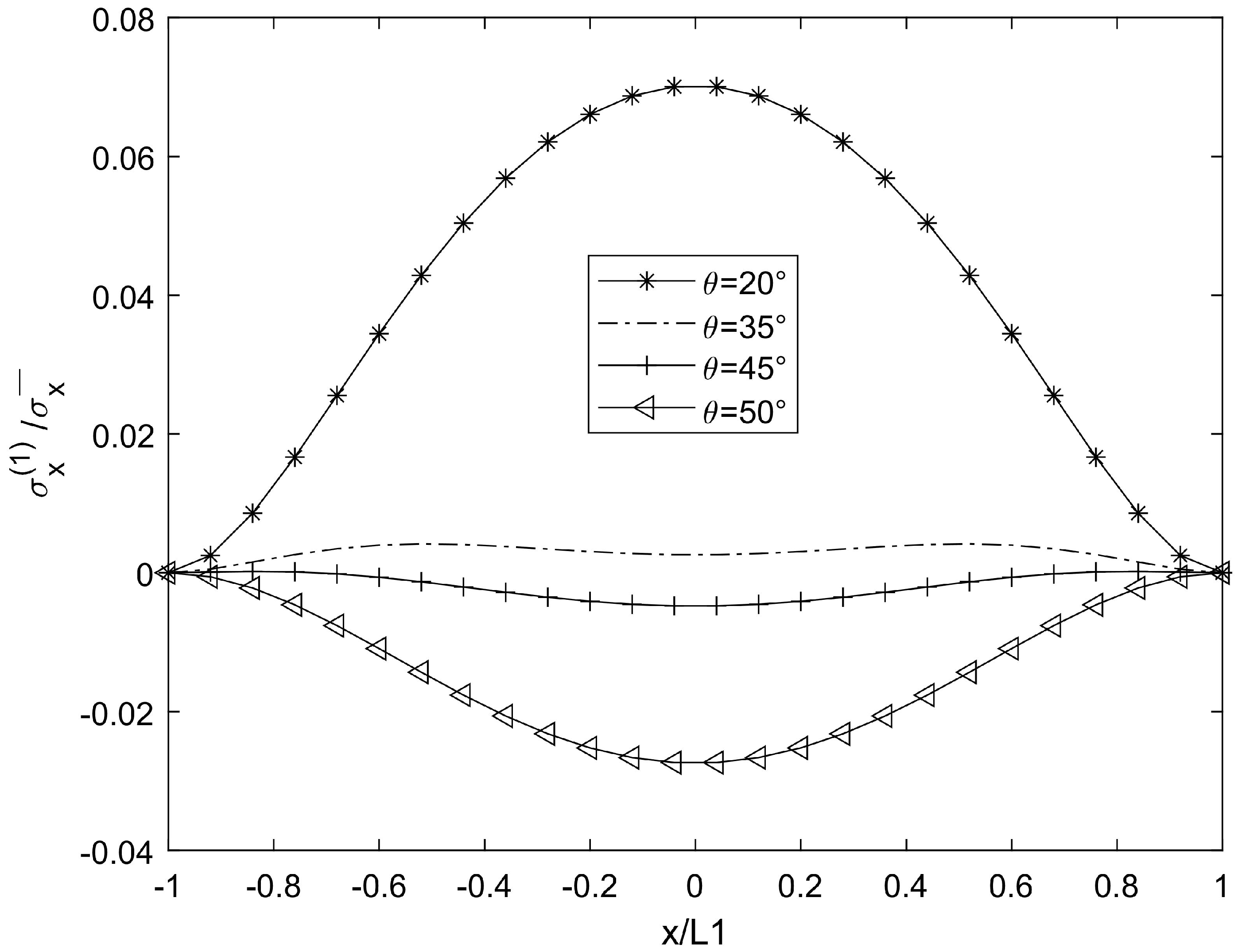
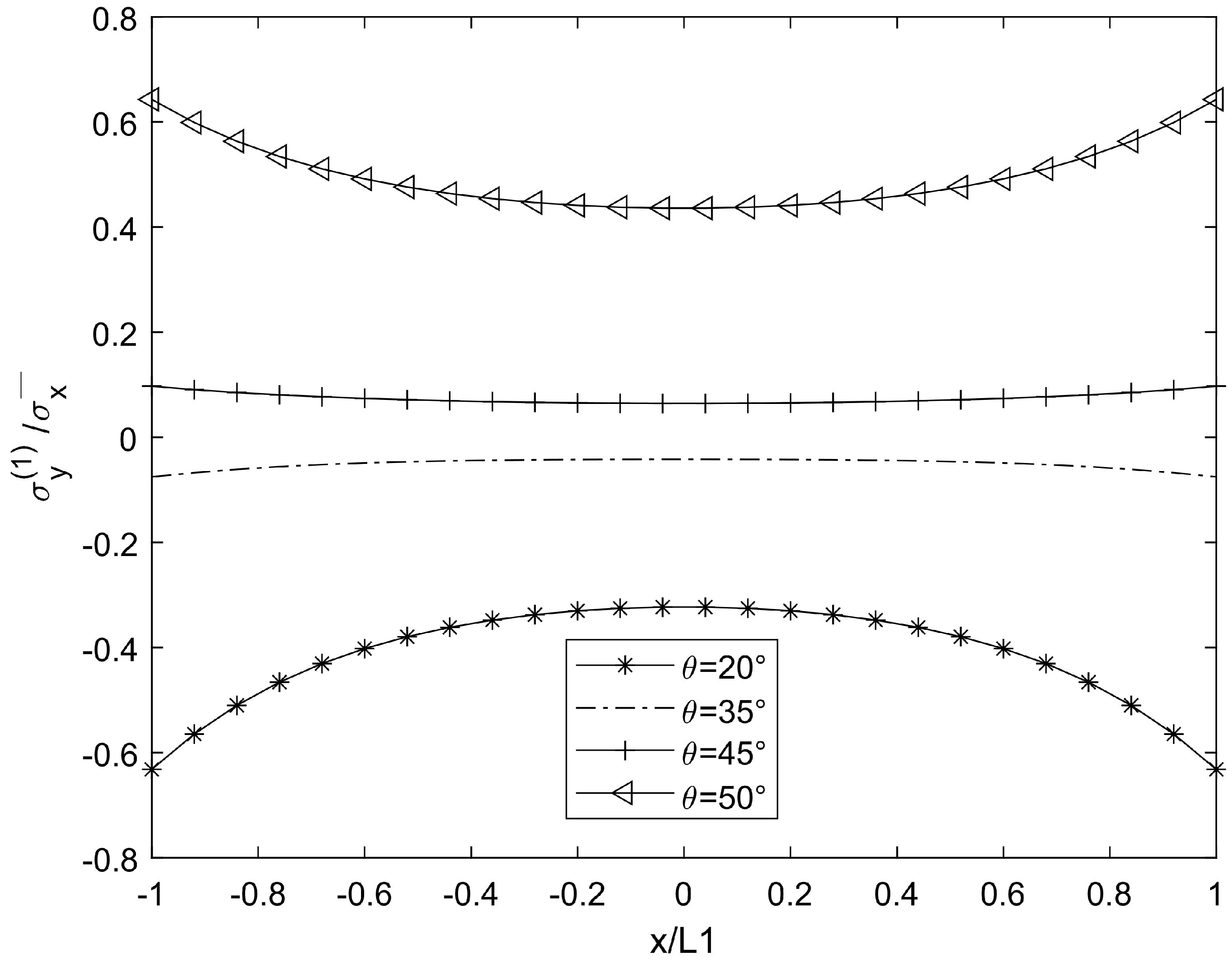
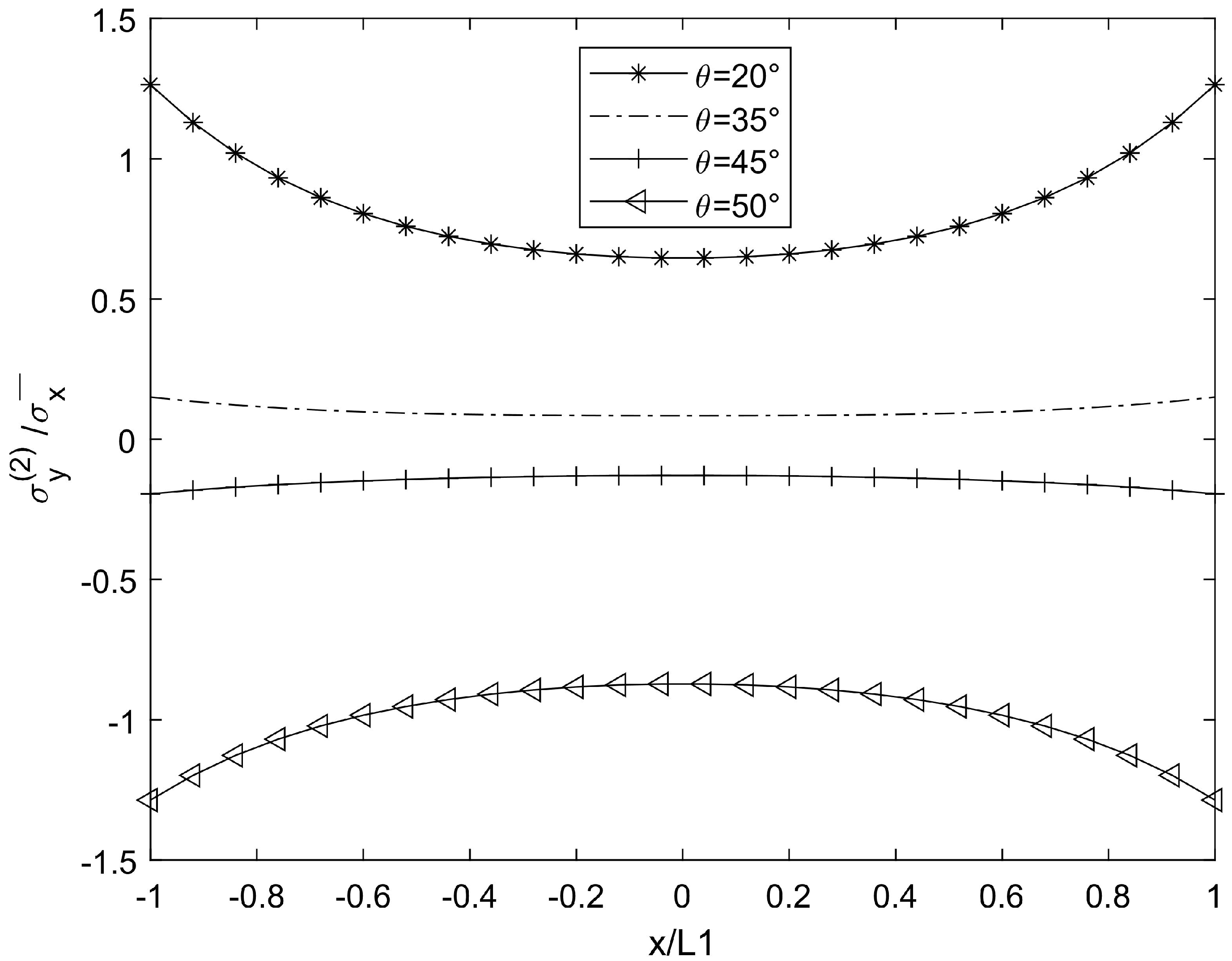
3. Numerical Results and Simulation

In order to calculate the effective mechanical properties of the 90° layer in composite laminates with cracks and compare the data with other studies, this paper selects glass epoxy resin as the material. The material parameters are from the articles of Hashin [28], Huang et al. [29,30], and P.A. Carraro [31]. The following table lists the material constants of the two kinds of glass/epoxy for the orthogonal laminates. The effective mechanical properties were calculated and compared with the experimental data from researchers Hashin [28] and Huang et al. [29,30] to verify the correctness of the model. The material constant of laminates [ 0 / 90 3 ] s and [ 0 / 90 2 ] s were calculated using glass/epoxy2 in Table 1. The results are shown in Table 2 and Table 3.
It can be seen from Table 2 and Table 3 that the calculated Young’s modulus is highly consistent with the data of Hashin [28], Huang [29,30], and others. Although there is a small error, the error range is less than 1%, which is within the normal allowable range. This result can be attributed to the fact that the principal axis of the orthogonal laminate material is aligned with the coordinate axis. Moreover, the tension is carried out in the direction of the principal axis, and there is no shear stress between the laminates.
For cases θ = 20°, 35°, 45°, and 50°, when the crack density is 0.5 (cr/mm) in the 90° plies, the material constant of the laminate is glass/epoxy 1, and the stress distribution results are shown in Figure 2, Figure 3, Figure 4, Figure 5, Figure 6, Figure 7, Figure 8, Figure 9, Figure 10, Figure 11, Figure 12 and Figure 13.
In Figure 3, Figure 4, Figure 5 and Figure 6, compared with the stress attenuation model of Hashin [28], the stress concentration effect at the crack center of the two models is significant, but the influence of the laying angle on local stress is further quantified. For example, Hashin [28] observed a similar normal stress distribution in orthogonal laminates, but did not consider the quantitative analysis of multi-angle laying. However, the experimental data of Huang [29] show that when the paving angle exceeds 45°, the increase in interlaminate normal stress can reach 15~20%, which is consistent with the stress jump phenomenon when θ = 60° in Figure 3 of this paper, verifying the sensitivity of the angle to stress concentration.
In Figure 7 and Figure 8, compared with the shear lag theory of Kashtalyan and Soutis [17], the predicted shear stress fluctuates nonlinearly when θ > 50°, which is consistent with the fluctuation amplitude of shear stress when θ = 50° in Figure 7 of this paper. However, this paper further reveals the modulation effect of interlayer constraint on the fluctuation amplitude using a variational method. However, according to the quadratic displacement hypothesis of Berthelot [16], the shear stress variation trend of the theoretical curve at a low θ value is consistent with that of the results in this paper (θ = 30°), and the difference appears in the high-θ-value region, which may be due to the finer interlayer coordination conditions of this model.
In Figure 9, Figure 10, Figure 11, Figure 12, Figure 13 and Figure 14, compared with the multi-layer crack model of Carraro [31], this research shows that when L1/t1 < 5, the stiffness degradation rate is significantly increased, which is highly consistent with Ex/Ex0 = 0.754 (predicted as 0.748 in the literature [31]) when L1/t1 = 3 in Figure 10, and the error is only 0.8%. Combined with the variational energy method of Vinogradov and Hashin [23], the lower limit theory of stiffness (error < 2%) and the results of this paper (Table 2, error < 1%) jointly verify the reliability of the minimum complementary energy principle in the analysis of cracked laminated plates.

4. Conclusions

In this paper, a series of key results are obtained in the field of composite laminates using a variational analysis method. Firstly, in the aspect of predicting stiffness reduction, variational analysis successfully realizes the effective prediction of stiffness reduction in [ 0 m / 90 n ] s laminates with different degrees, providing a reliable means for the prediction of material properties. Secondly, the stress distribution of laminates caused by matrix cracks in 90° laminates is discussed in detail and in depth. The interlaminate stress and in-plane stress distribution of each ply are accurately calculated, which is in good agreement with the existing experimental data and verifies the accuracy and reliability of the analysis method. It is worth emphasizing that the analysis method used in this study has a wide range of applicability, not only to specific ply structures, but also to multi-angle-ply laminates, which greatly expands the application scope of this method in composite research. Through the in-depth analysis of interlaminate stress and in-plane stress distribution, the formation of matrix cracks and local interlaminate delamination can be predicted in advance and effectively, which is of great significance for improving the structural integrity and safety assessment of composite laminates.

Author Contributions

Methodology, X.W.; Writing—original draft, B.X.; Writing—review & editing, Z.H.; Supervision, F.C. All authors have read and agreed to the published version of the manuscript.

Funding

This research was funded by Natural Science Foundation of China, grant number 11862007.

Data Availability Statement

The original contributions presented in this study are included in the article. Further inquiries can be directed to the corresponding author.

Conflicts of Interest

The authors declare no conflict of interest.

References

  1. Shen, G.; Hu, G. Mechanics of Composite Materials; Tsinghua University Press: Beijing, China, 2013; Volume 9, pp. 30–44. [Google Scholar]
  2. De Luca, A.; Greco, A.; Rezazadeh, N.; Perfetto, D.; Aversano, A. Guided Waves Propagation in Additively Manufactured GF30-PA6 Panel. Macromol. Symp. 2024, 413, 2400042. [Google Scholar]
  3. Fikry, M.J.M.; Ogihara, S.; Vinogradov, V. The effect of matrix cracking on mechanical properties in FRP laminates. Mech. Adv. Mater. Mod. Process. 2018, 4, 3. [Google Scholar]
  4. Ramezani, H.; Kazemirad, S.; Shokrieh, M.; Mardanshahi, A. Effects of adding carbon nanofibers on the reduction of matrix cracking in laminated composites: Experimental and analytical approaches. Polym. Test. 2021, 94, 106988. [Google Scholar]
  5. Ghadami, M. An anisotropic nonlinear multiscale damage model for mechanical behavior of a composite laminate with matrix cracks. Meccanica 2023, 58, 1809–1822. [Google Scholar]
  6. Chaupal, P.; Rohit, S.; Rajendran, P. Matrix cracking and delamination detection in GFRP laminates using pre-trained CNN models. J. Braz. Soc. Mech. Sci. Eng. 2023, 45, 136. [Google Scholar]
  7. Fakoor, M.; Rafiee, R.; Sheikhansari, M. The influence of fiber-crack angle on the crack tip parameters in orthotropic materials. Proc. Inst. Mech. Eng. Part C J. Mech. Eng. Sci. 2017, 231, 418–431. [Google Scholar]
  8. Farrokhabadi, A.; Bahrami, M.; Babaei, R. Predicting the matrix cracking formation in symmetric composite laminates subjected to bending loads. Compos. Struct. 2019, 223, 110945. [Google Scholar]
  9. Mohammadi, B.; Pakdel, H. Fatigue driven matrix crack propagation in laminated composites. Mater. Des. 2018, 146, 108–115. [Google Scholar]
  10. Pakdel, H.; Mohammadi, B. Experimental observation and energy based analytical investigation of matrix cracking distribution pattern in angle-ply laminates. Theor. Appl. Fract. Mech. 2017, 92, 146–154. [Google Scholar]
  11. Qi, W.; Huang, J.; Yao, W.; Shen, H. A damage model for matrix cracks in composite laminates under fatigue loading based on continuum damage mechanics. Int. J. Fatigue 2024, 184, 108315. [Google Scholar]
  12. Rezaei Jafari, S.; Farrokhabadi, A.; Montesano, J. The effect of staggered matrix crack induced delamination growth on the mechanical properties of cross-ply laminates. Compos. Struct. 2021, 272, 114196. [Google Scholar]
  13. Socci, C.A.; Kassapoglou, C. Prediction of matrix crack initiation and evolution and their effect on the stiffness of laminates with off-axis plies under in-plane loading. Compos. Sci. Technol. 2020, 200, 108427. [Google Scholar]
  14. Yuan, M.; Zhao, H.; Liu, S.; Ren, H.; Zhang, B.; Chen, J. Prediction of matrix-cracking-induced stiffness degradation of cross-ply laminates based on data-driven method. Compos. Sci. Technol. 2022, 230, 109716. [Google Scholar]
  15. Zhang, J.; Fan, J.; Soutis, C. Analysis of multiple matrix cracking in composite laminates. Part 1, In-plane stiffness properties. Composites 1992, 23, 291–298. [Google Scholar]
  16. Berthelot, J.M. Analysis of the transverse cracking of cross-ply laminates: A generalized approach. J. Compos. Mater. 1997, 31, 1780–1805. [Google Scholar]
  17. Kashtalyan, M.; Soutis, C. Analysis of composite laminates with intra-and interlaminate damage. Prog. Aerosp. Sci. 2005, 41, 152–173. [Google Scholar]
  18. Hajikazemi, M.; Sadr, M.; Hosseini-Toudeshky, H.; Mohammadi, B. Thermo-elastic constants of cracked symmetric laminates: A refined variational approach. Int. J. Mech. Sci. 2014, 89, 47–57. [Google Scholar]
  19. Carraro, P.A.; Maragoni, L.; Quaresimin, M. Stiffness degradation of symmetric laminates with off-axis cracks and delamination: An analytical model. Int. J. Solids Struct. 2021, 213, 50–62. [Google Scholar]
  20. Wang, F.; Wang, B.; Kong, F.; Ouyang, J.; Ma, T.; Chen, Y. Assessment of degraded stiffness matrices for composite laminates under low-velocity impact based on modified characteristic length model. Compos. Struct. 2021, 272, 114145. [Google Scholar] [CrossRef]
  21. Herrmann, L.; Mikkelsen, L.P.; Legarth, B.N.; Duddeck, F.; Niordson, C.F. An efficient stiffness degradation model for layered composites with arbitrarily oriented tunneling and delamination cracks. Compos. Sci. Technol. 2022, 230, 109729. [Google Scholar]
  22. Wu, T.; Wang, G.; Wang, J.; Wang, Y.; Xu, R. Variational principles of laminated plates considering interlayer slip. Compos. Struct. 2022, 281, 114937. [Google Scholar] [CrossRef]
  23. Vinogradov, V.; Hashin, Z. Variational analysis of cracked angle-ply laminates. Compos. Sci. Technol. 2010, 70, 638–646. [Google Scholar]
  24. Behera, A.; Thawre, M.M.; Ballal, A. Effect of matrix crack generation on Fatigue life of CFRP multidirectional laminates. Mater. Today Proc. 2018, 9 Pt 3, 20078–20084. [Google Scholar] [CrossRef]
  25. Li, S.; Hafeez, F. Variation-based cracked laminate analysis revisited and fundamentally extended. Int. J. Solids Struct. 2009, 46, 3505–3515. [Google Scholar] [CrossRef]
  26. Katerelos, D.G.; Mccartney, L.N.; Galiotis, C. Local strain re-distribution and stiffness degradation in cross-ply polymer composites under tension. Acta Mater. 2005, 53, 3335–3343. [Google Scholar] [CrossRef]
  27. Mohammad-Zaheri, F.; Mohammadi, B.; Taheri-Behrooz, F. Prediction of stress distribution and stiffness degradation in fiber metal laminates containing matrix cracking. Compos. Struct. 2023, 311, 116820. [Google Scholar]
  28. Hashin, Z. Analysis of orthogonally cracked laminates under tension. J. Appl. Mech. 1987, 54, 872–879. [Google Scholar]
  29. Huang, Z.; Yi, S.; Chen, H.; He, X. Parameter analysis of damaged region for laminates with matrix defects. J. Sandw. Struct. Mater. 2021, 23, 580–620. [Google Scholar]
  30. Huang, Z.Q.; Nie, G.H.; Chan, C.K. An exact solution for stresses in cracked composite laminates and evaluation of the characteristic damage state. Compos. Part B Eng. 2011, 42, 1008–1014. [Google Scholar]
  31. Carraro, P.A.; Quaresimin, M. A stiffness degradation model for cracked multidirectional laminates with cracks in multiple layers. Int. J. Solids Struct. 2015, 58, 34–51. [Google Scholar]
Figure 1. Glass epoxy laminate structure.
Symmetry 17 00495 g001
Figure 2. Model of cracked element.
Symmetry 17 00495 g002
Figure 3. Graph illustrating σ x in 90° ply for [ θ 1 / 90 2 ] s laminate.
Symmetry 17 00495 g003
Figure 4. Graph illustrating σ x in θ ply for [ θ 1 / 90 2 ] s laminate.
Symmetry 17 00495 g004
Figure 5. Graph illustrating σ y in 90° ply for [ θ 1 / 90 2 ] s laminate.
Symmetry 17 00495 g005
Figure 6. Graph illustrating σ y in θ ply for [ θ 1 / 90 2 ] s laminate.
Symmetry 17 00495 g006
Figure 7. Graph illustrating τ x y in 90° ply for [ θ 1 / 90 2 ] s laminate.
Symmetry 17 00495 g007
Figure 8. Graph illustrating τ x y in θ ply for [ θ 1 / 90 2 ] s laminate.
Symmetry 17 00495 g008
Figure 9. Graph illustrating τ z x in 90° ply for [ θ 1 / 90 2 ] s laminate.
Symmetry 17 00495 g009
Figure 10. Graph illustrating τ z x in θ ply for [ θ 1 / 90 2 ] s laminate.
Symmetry 17 00495 g010
Figure 11. Graph illustrating τ z y in 90° ply for [ θ 1 / 90 2 ] s laminate.
Symmetry 17 00495 g011
Figure 12. Graph illustrating τ z y in θ ply for [ θ 1 / 90 2 ] s laminate.
Symmetry 17 00495 g012
Figure 13. Graph illustrating σ z in 90° ply for [ θ 1 / 90 2 ] s laminate.
Symmetry 17 00495 g013
Figure 14. Graph illustrating σ z in θ ply for [ θ 1 / 90 2 ] s laminate.
Symmetry 17 00495 g014
Table 1. Material constant.
E A /GPa E T /GPa G A /GPa G T /GPa v A v T t 0 /mm
Glass/epoxy142.013.03.604.500.250.380.330
Glass/epoxy241.713.03.404.580.300.420.100
Table 2. Young’s modulus attenuation of laminates: [ 0 / 90 3 ] s .
L1/t1PresentHuang et al. [30]Huang et al. [29]Hashin [28]
Ex/Ex0Ex/Ex0Ex/Ex0Ex/Ex0
500.9870.9780.9800.980
200.9580.9480.9520.951
100.9140.9020.9080.907
50.8370.8210.8320.830
30.7540.7350.7480.745
20.6690.6530.6650.661
10.5560.5510.5530.548
0.50.5320.5290.5290.524
Table 3. Young’s modulus attenuation of laminates: [ 0 / 90 2 ] s .
L1/t1PresentHuang et al. [30]Huang et al. [29]Hashin [28]
Ex/Ex0Ex/Ex0Ex/Ex0Ex/Ex0
500.9980.9890.9900.990
200.9840.9740.9760.975
100.9610.9500.9540.953
50.9180.9050.9110.910
30.8680.8540.8610.859
20.8220.8120.8160.813
10.7840.7780.7780.775
0.50.7790.7730.7730.770
Disclaimer/Publisher’s Note: The statements, opinions and data contained in all publications are solely those of the individual author(s) and contributor(s) and not of MDPI and/or the editor(s). MDPI and/or the editor(s) disclaim responsibility for any injury to people or property resulting from any ideas, methods, instructions or products referred to in the content.

