Article

Borehole-Based Monitoring of Mining-Induced Movement in Ultrathick-and-Hard Sandstone Strata of the Luohe Formation

1
State Key Laboratory of Coal Resources and Safe Mining, China University of Mining and Technology, Xuzhou 221116, China
2
School of Mines, China University of Mining and Technology, Xuzhou 221116, China
3
School of Safety Science and Engineering, Henan Polytechnic University, Jiaozuo 454003, China
4
Institute of Geotechnical Engineering, School of Transportation, Southeast University, Nanjing 211189, China
5
Disaster Prevention Research Institute, Shanxi Changwu Tingnan Coal Co. Ltd., Xianyang 713602, China
*
Author to whom correspondence should be addressed.
Minerals 2021, 11(11), 1157; https://doi.org/10.3390/min11111157
Submission received: 29 September 2021 / Revised: 12 October 2021 / Accepted: 18 October 2021 / Published: 21 October 2021

Abstract

:
Water outbursts and rock bursts often occur during the mining of coal seams under water-rich sandstone strata with thicknesses exceeding 50 m, otherwise called ultrathick-and-hard strata (UTHS), which are common throughout the mining areas of northwestern China. It is important to understand the behaviors of their movement and the evolution of their internal fractures to inform the formulation of effective disaster prevention. Due to the presence of the Luohe Formation UTHS in the overburden of the Tingnan Coal Mine in the Binchang mining area and the powerful mining-induced pressure (MIP) events that occurred during the excavation of Panel #2, the internal strata movement of the overburden and the evolution of its fractures were monitored in situ by fiber optic and multipoint borehole extensometers (MPBX) during the excavation of Working Face #207. It was found that a large number of ring-shaped fractures were observed at 24.8–81 m above the lower boundary of the Luohe Formation—in areas above the goaf of Working Face #206—before Working Face #207 was mined. When Working Face #207 was mined, the fractures that were originally located in the deep strata of the Luohe Formation started to close and migrate towards shallow strata. Crack closure and migration were also observed during the monitoring of internal strata movement. Furthermore, the final displacements of Y1-1-1#, Y1-2-2#, and Y1-2-3# relative to the surface were 77, 248, and 134 mm, which were very small relative to the surface subsidence of 1380 mm. It was found that mining-induced perturbations caused the Luohe Formation UTHS to subside continuously and no risk of a large and sudden break would occur in the Luohe Formation UTHS during the mining of Working Face #207. The results of this study provide important data for the safety of mining operations at Working Face #207, which were validated by microseismic monitoring during the mining of it.

1. Introduction

Northwestern China is currently the most important coal-mining region in China. In 2019, the raw coal production of Inner Mongolia (1.035 billion tons), Shanxi (0.971 billion tons), Shaanxi (0.634 billion tons), and Ningxia (71 million tons) accounted for 72.3% of China′s total raw coal production (3.75 billion tons). However, many of the coal mines in northwestern China are located in the Ordos Basin, whose coal seams are often covered by one or multiple layers of >50 m thick water-bearing sandstone strata, also known as ultrathick-and-hard strata (UTHS). The total thicknesses of these strata—such as the Luohe Formation UTHS in the Binchang mining area and the Zhiluo Formation UTHS in Ningdong—are often in excess of 200 m. Due to the immense thickness and strength of such UTHS, they often cause intense long-distance mining-induced increases in pressure, that is, mining-induced pressure (MIP), alongside coal-gas outbursts and the supporting of collapsed-water inrush disasters when their underlying coal seams are mined [1,2,3,4,5,6,7]. Therefore, UTHS pose a threat to the safety of coal mines.
To address the aforementioned problems in predicting and preventing mining-induced disasters, it is necessary to have a comprehensive understanding of the movements and behaviors of the UTHS. Mondal used the mine-induced microseismic data and monitored the stressed zones in the hanging overlying strata above and behind the panel to monitor the stress levels and fractures in the overlying strata, as well as for the spatio-temporal forecasting of roof-falls [8,9]. Zhang studied the stability of the UTHS-coal seam system in the Gaozhuang Coal Mine by developing a compatible deformation model of the system, proposing disaster prevention and mitigation techniques based on it [10]. Wang et al. [11], studied the effects of each stage of the mining process on the overburden in a coal seam under a set of UTHS comprising magmatic rock, as well as studied the deformation and failure modes of such magmatic rock. To address the dangers associated with coal mining under UTHS, Xuan et al. [12,13] proposed that grout may be injected from surface boreholes to fill the space beneath these strata so as to reduce the load on coal pillars and thus prevent mining disasters. Han et al. [14] created a theoretical model for UTHS and thus developed as well as applied a key strata-based model for subsidence predictions in the presence of UTHS so as to address the inadequacies of current subsidence prediction methods in these scenarios. Ning et al. [15] proposed measures to prevent and mitigate mining disasters in coal mines with a UTHS overburden under a variety of conditions. The aforementioned studies have revealed the general characteristics and behaviors of UTHS breaks and movements based on theoretical analyses, simulations, and experiments. They have contributed significantly toward our mechanistic understanding of mining disasters and informed disaster prevention work. Nonetheless, the in situ monitoring of internal UTHS movement is rarely performed due to the complexity and expense of such endeavors.
Most of the strata movement monitoring work that has been performed thus far has been limited to depths of less than 200 m. For instance, Scott monitored postconstruction settlement of the embankment with conventional survey monuments on abutment wingwalls and on multipoint borehole extensometers (MPBX) in the roadway shoulders [16]. Avramov et al. used MPBX to monitor the shallow displacement of rock strata and the borehole depth was small [17,18,19,20,21]. Ingram et al. studied the overburden movement that was caused by the mining of a longwall panel—with a 270 m wide face, buried depths of 95–105 m, and an extraction thickness of 1.8 m—by setting up monitoring lines with multipoint borehole extensometers (MPBXs) in the overburden. The MPBXs were installed by injecting grout into the boreholes [22]. Zhu et al. monitored internal strata movement by mounting four-point surface extensometers in boreholes and revealed how strata movement is controlled by key strata at shallow depths [23]. Yang et al. conducted a borehole-based investigation on strata movement in the ultra-high working face of the shallow Shendong Coal Mine, with a mining depth of less than 180 m [24]. However, it is significantly more difficult to drill boreholes or monitor strata movement at large buried depths. The authors of [25] planned to use a multi-wire borehole instrumentation system to monitor strata movement and changes in strata permeability during the repeated mining of multiple working faces at a monitoring depth of 424 m. However, due to the difficulty of drilling such a deep borehole, they were only able to install their instruments at a depth of 165 m. Therefore, the increase of mining depth is a major challenge to the monitoring of strata movement.
In [26,27,28], boreholes drilled from the surface were used in conjunction with underground rock-pressure monitoring to probe how the movement of high-level strata related to and affected subsurface rock pressure. However, these studies were not able to provide a high level of detail about the internal movement of the strata.
In the Binchang Mining Area (the study area), the depth of the lower boundary of the Luohe Formation UTHS is approximately 300–400 m, while the depth of its coal seam reaches 600 m. It is difficult to monitor strata movement at these depths using conventional methods. Some studies have used microseismic signals and distributed fiber optic lines as media to monitor strata movement and deformation at great depths. For example, Yu et al. [29] used microseismic monitoring to study the behavior of overburden failures during top-coal caving mining in the Datong Mining Area. Cheng et al. [30] analyzed microseismic signals to identify the areas that had been damaged during mining-induced overburden movements and thus established a new approach for studying the damaged areas of overburden strata. However, it is difficult to quantitatively determine the extent of the motion-induced damage using this method. By installing three types of fiber optic lines in two boreholes, Liu et al. [31] studied the deformation and damage of mining-perturbed strata and found that fiber optic lines at different depths were deformed in different ways. Cappa et al. [32] used fiber optic cables to characterize highly heterogeneous elastic displacement fields in fractured rocks. However, fiber optic cables can snap when the working face passes through the monitoring boreholes or when the strata movement and deformations are large, leading to data loss. Although distributed fiber optic sensing can be used to increase monitoring depth, this technique is best suited to areas where strata movement is relatively small. If one is to monitor strata movement in the water-bearing Luohe Formation UTHS, one must develop new methods and devices that are suitable for strata movement monitoring in deeply buried water-rich strata with large mining-induced deformations.
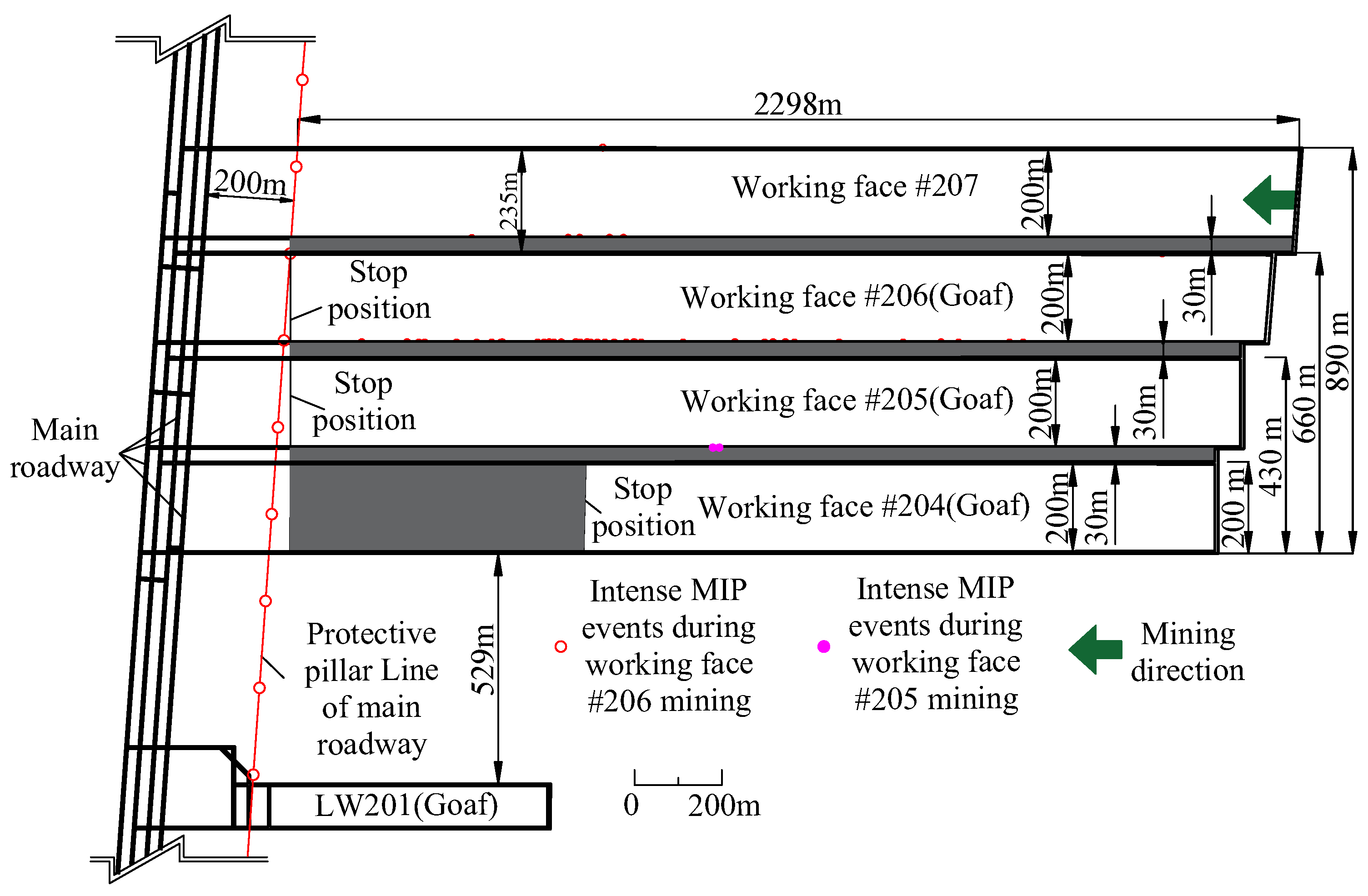
The Binchang mining area is located under the water-bearing UTHS of the Luohe Formation. In the Tingnan Coal Mine, which lies in this area, the mining of Working Face #204 in Panel #2 proceeded normally. However, two intense MIP events occurred in its roadways when the adjacent Working Face #205 was mined. There were 43 intense MIP events that occurred during the mining of Working Face #206, which led to severe roadway deformation and equipment damage. When the mining area increased in size, the frequency and intensity of the MIP events also increased significantly; even the roadway that was fully excavated 235 m away from the mining boundary of Working Face #206 experienced MIP events. As the mining area of the panel will increase as Working Face #207 is mined, there is a possibility of a large break occurring in the water-bearing Luohe Formation UTHS and causing a major disaster, such as sharp increases in rock pressure or water inrushes. This is the most pressing safety issue for the mining of Tingnan Coal Mine′s Panel #2. Consequently, an in situ investigation needed to be performed to assess the damage that occurred in the Luohe Formation UTHS after the mining of Working Face #206. Furthermore, the movement of this UTHS needed to be monitored in real time during the mining of Working Face #207 to help determine whether a large break in the UTHS might occur above its goaf. This would provide the basic data for the formulation of disaster prevention and mitigation plans at this coal mine.

2. Materials: Mining Conditions of Panel #2 in the Tingnan Coal Mine

The Tingnan Coal Mine is located at the center of the Binchang Mining Area in the Huanglong Jurassic Coalfield. It is near Tingkou Town in Changwu County (Xianyang City, Shaanxi Province). The only mineable coal seam in this mine is the #4 coal seam of the Jurassic system, whose thickness varies from 1.00 m up to 23.24 m (10.75 m thick on average). The Tingnan Coal Mine consists of four panels. Panel #1 was mined first, while Panel #2 and #3 are currently being mined. Panel #4 is still being developed. Panel #2 is located at the northern end of the mine and is adjacent to Panel #4 on its western side.

2.1. Hydrogeographic Conditions

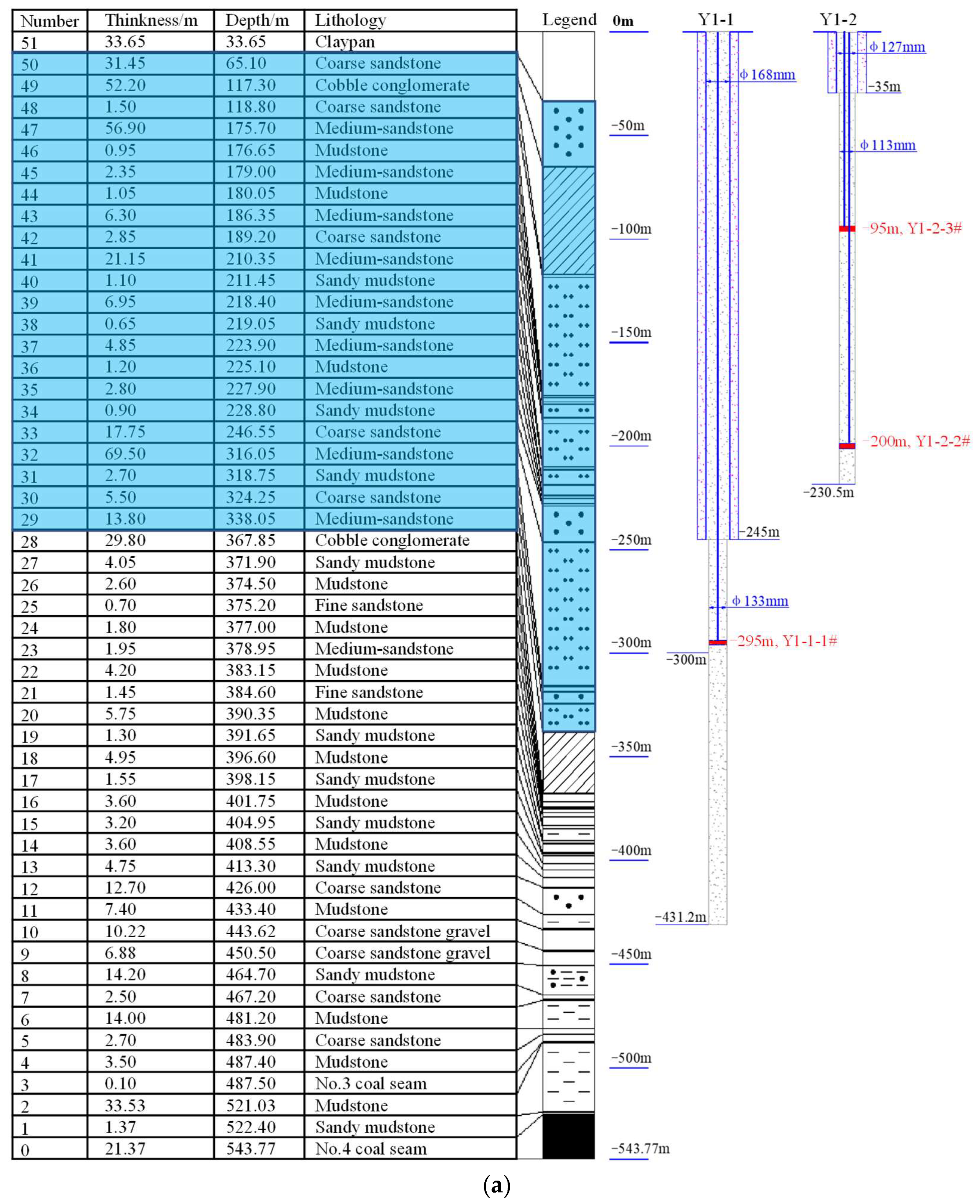
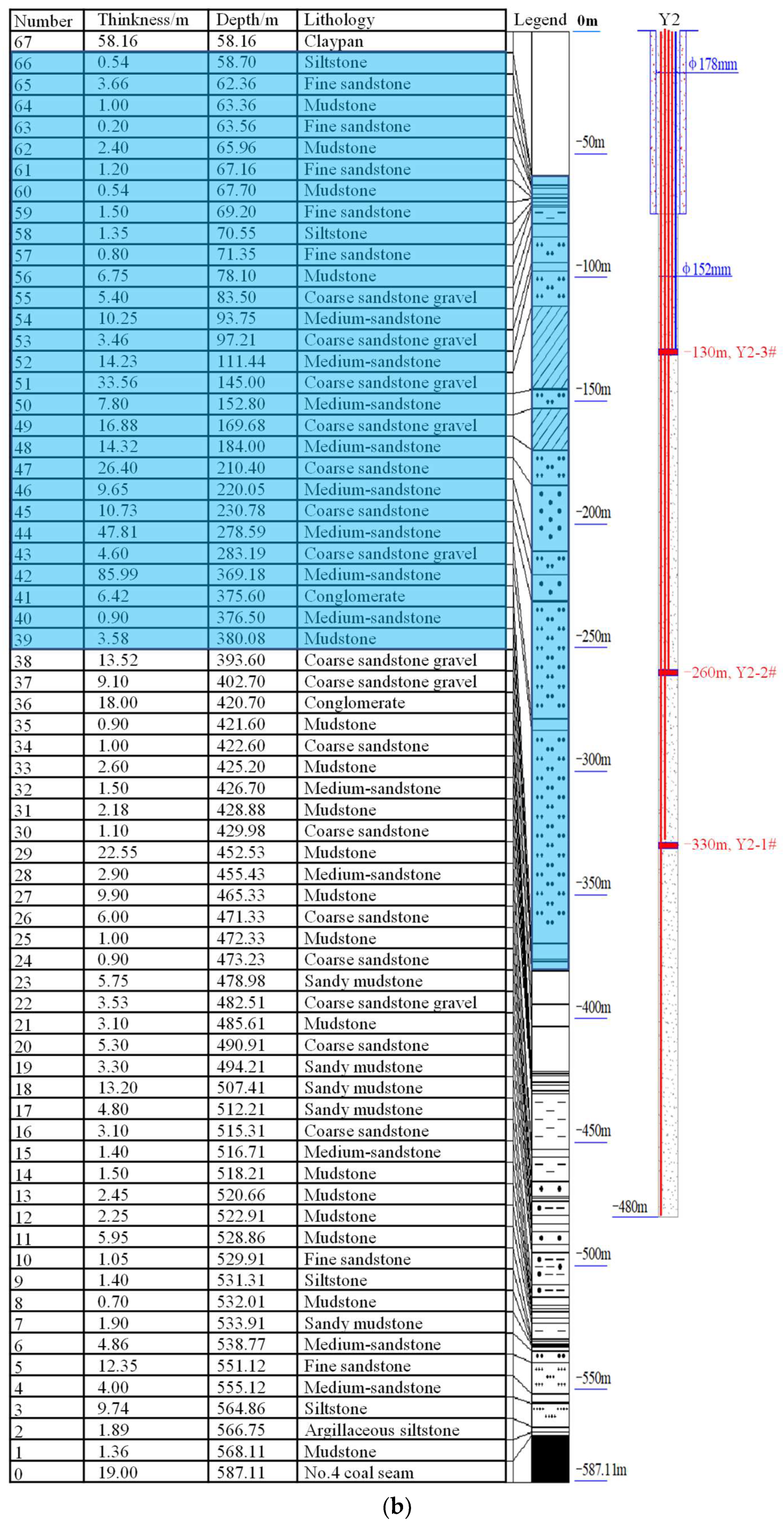
The mine is located in a Cenozoic artesian basin in the Ordos Basin whose stratigraphy consists of Lower Cretaceous (K1), Jurassic (J), and Upper Triassic (T3) systems. The strata of Panel #2 can be divided based on its hydrological characteristics into five water-bearing strata and three impermeable layers. The Luohe Formation—which consists of interbedded coarse and fine conglomerates and sandstones with joints—is present throughout these strata. The permeability coefficients of these strata range from 0.074 to 0.908 m/d. The total thickness of the Luohe Formation in Panel #2 is 287.1 m and it consists of several >50 m thick sandstone or sandstone–conglomerate layers, as well as other thinner strata. The composite stratigraphic column of this area is shown in Figure 1.

2.2. Mining Conditions of the Working Face

In Panel #2, Working Faces #201, #204, #205, and #206 have already been mined. Since Working Face #201 is 529 m away from the other working faces in Panel #2, it is unlikely to have any influence on or be influenced by them. Working Face #204 is the first mining face and it was mined from November 2011 to November 2012. The face width, advancement length, and extraction height of this face is 200, 1450, and 6 m, respectively. Working Face #205 was mined from June 2013 to November 2014, with a face width of 200 m, an advancement length of 2173 m, and an extraction height of 6 m. Working Face #206 was mined from January 2015 to April 2016, with a face width of 200 m, an advancement length of 2240 m, and an average extraction height of 7.5 m. Coal pillars at 30 m intervals were left between the working faces and a 200 m protective coal pillar was left between the primary roadway on the western side and the terminal mining lines of Working Faces #205 and #206. Working Face #204 has a shorter advancement length than Working Faces #205 and #206 due to the protective coal pillar that was left behind to protect overlying buildings on the surface. The layout of the working faces in Panel #2 is shown in Figure 2.
Working Face #207 was immediately mined after Working Face #206 had been fully extracted, with its working face having a face width of 200 m, advancement length of 2298 m, design extraction height of 6–9 m (7.5 m on average), and coal seam dip angles of 0–8°. Coal pillars at 30 m intervals were left in the goaf between Working Faces #207 and #206.

2.3. Intense MIP Events in the Working Face Roadways

The positions at which intense MIP events occurred in the working faces of Panel #2 in the Tingnan Coal Mine are shown in Figure 2. During the mining of Working Face #205, two intense MIP events occurred in its tailgate, adjacent to the goaf of Working Face #204. Forty-three MIP events occurred during the mining of Working Face #206 (36 in its tailgate, 1 in its haulage gate, 5 in the tailgate of Working Face #207, and 1 in the haulage gate of Working Face #207). It should be noted that the two mining roadways of Working Face #207 had already been fully excavated when Working Face #206 was being mined. Furthermore, a 30 m wide interval coal pillar was present between the tailgate of Working Face #207 and the goaf of Working Face #206, and the haulage roadway of Working Face #207 was separated by 235 m of solid coal from the goaf of Working Face #206. The occurrence of intense MIPs over such a long distance is very rare.
It has been shown in previous studies that the occurrence of MIP events is directly related to the distribution of stress anomalies in the coal body. Based on simulations, the authors of [33] found that increasing the thickness of the key layer also increased the area of effect and stress concentration coefficients of the bearing stresses in coal walls. In [34], the key layer theory was used to analyze the distribution of mining-induced stresses in the presence of UTHS: the authors found that the unique structure of the UTHS overburden affected the distribution of mining-induced stresses. Consequently, the presence of UTHS in the overburden was a threat to the safety of coal mines. In [12], authors described an episode where the mining of a coal seam 180 m away from a 120 m thick magmatic rock stratum led to coal-gas outbursts. In this mine, nothing happened when Working Faces II1022 and II1024 were being mined. However, a severe coal-gas outburst occurred when the haulage gate of Working Face II1026 was being excavated some 150 m away from the boundaries of the mined area. It was found that if the magmatic rock UTHS was absent, the stress concentration coefficients would converge to a fixed value very rapidly and the area of effect of the bearing stresses would be small. However, when the magmatic rock UTHS was present, this stratum would remain intact while the coal seam was being mined, which led to abnormalities in the distribution of mining-induced stresses in the coal walls around the goaf. As the mining area expanded in size, the stress concentration coefficients on both sides of the goaf increased linearly, becoming difficult to stabilize. Moreover, the area affected by mining-induced stresses also expanded significantly. The presence of the magmatic rock UTHS increased the bearing stress at the haulage gate of Working Face II1026 by more than 5.7 MPa and the region affected by bearing stress was more than 255 m in length. By comparing our study area to this case, we believe that it is the presence of the Luohe Formation UTHS above the Tingnan Coal Mine that caused intense MIP events in the mining roadways of Working Faces #205 and #206, as well as the far-removed haulage gate of Working Face #207.

2.4. Surface Subsidence

Other than the intense MIP events that occurred in the working face roadways of Panel #2, the subsidence of the surface was also significantly different from the norm. Before the working faces of Panel #2 were mined, surface subsidence observation lines were installed along the inclination of the panel. After the #204, #205, and #206 working faces of Panel #2 were mined, the mining lengths along the inclination and strike were 660 and 2240 m, respectively, at an average depth of 550 m. The maximum subsidence that was measured on the surface was 1.925 m [14]; given that the average extraction height was 7.5 m, this corresponds to a subsidence coefficient of only 0.256. If the UTHS was not present in the overburden, the surface should have subsided significantly when the size of the goaf in the inclination and strike reached 1.2–1.4× the extraction height of the coal seam, and the surface subsidence coefficient should have ranged from 0.55 to 0.84 [35]. The predicted surface subsidence of Panel #2 without the UTHS is 4.1–6.3 m. Consequently, the presence of the Luohe Formation UTHS in the Tingnan Coal Mine was the main reason for the decreased surface subsidence of this area.
The mining of Working Face #207 in Panel #2 will undoubtedly widen the mining area of the panel and the motional behaviors of the overlying Luohe Formation UTHS will determine whether this will cause even more dangerous MIP events. Therefore, it is absolutely critical to monitor the movement of the Luohe Formation UTHS in Panel #2 during the mining of Working Face #207, as this will provide important data for the safety of the mining operations in this area.

3. Methods and Design of Monitoring the Movement of the UTHS

Mining-induced strata movement is a very complex process. To reveal the law of stratum movement, it is necessary to use various means and comprehensively analyze its monitoring data as much as possible. Therefore, this paper hopes to achieve this goal through stratum detection before the mining and real-time monitoring of the mining process.

3.1. Method of Fracture Detection

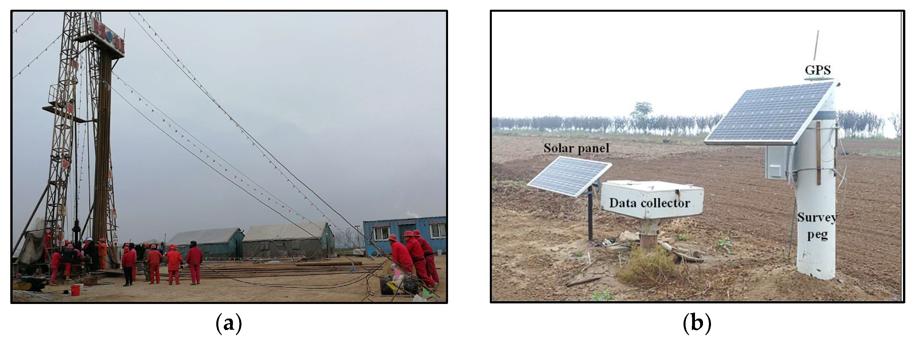
During the drilling process, a method for monitoring drilling fluid loss (as described by Figure 3a) was used to survey cracks inside the borehole so as to determine the state of fracture development in it. During or after the drilling process, a peephole (see Figure 3b) was used to survey fractures inside the borehole (now located inside the UTHS) to ascertain the distribution of fractures in the strata.

3.2. Method of Strata Movement Monitoring

After the boreholes had been drilled, strata movement detectors were installed inside them. This was done in two ways as follows.
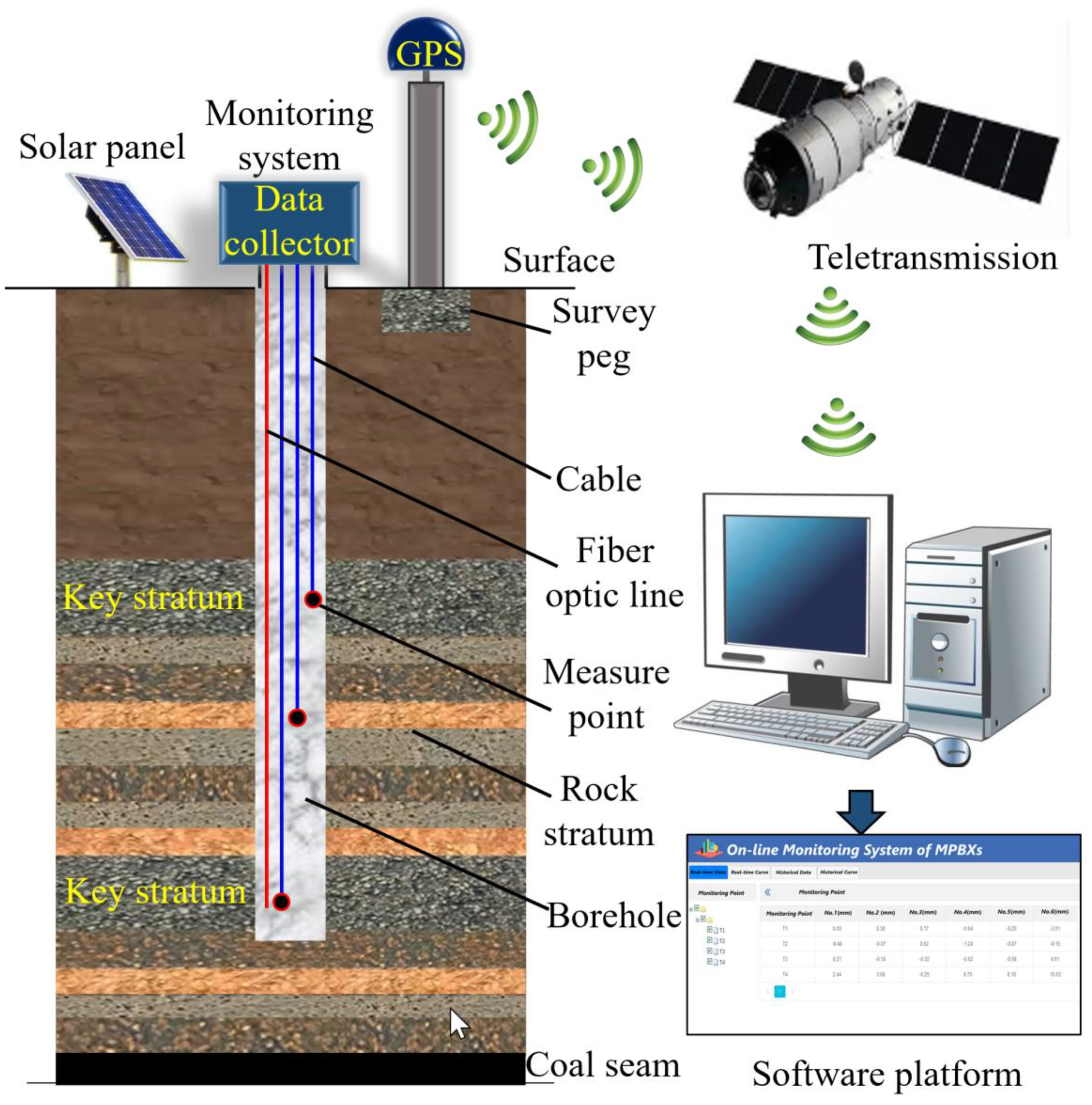
The first method was to place an armored cable with MPBX in the borehole. MPBX is an instrument used to measure the differential vertical movements of the selected rock horizons in a borehole relative to the surface. Each MPBX unit comprises several measuring points, pressure-resistant hollow plastic cables, steel cables, and encoders with tension. These measuring points will experience the same movement as the strata that they are anchored on. Internal steel cables were used to transmit relative movement data between the measuring point and the ground to a monitoring device at the opening of the borehole, which was then transmitted to a software platform, allowing for the strata movement to be remotely monitored. The absolute movement of the layer where the measuring point was located could be obtained by combining the surface subsidence data.
In addition, in order to master the deformation characteristics of rock strata, the second method was to use distributed fiber optic lines to monitor strata deformation. Before Working Face #207 was mined, distributed fiber optic lines had been placed in the boreholes and were cemented with grout to ensure that the lines were bound to the strata. Any change that occurred in the overburden during the mining of the working face would then cause the fiber optic-containing sensing lines in the boreholes to deform. One could then measure the movement and deformations that occurred in the strata by sampling and comparing the changes that occurred in the fiber optic lines themselves. After installation, the initial value was monitored and the later periodic monitoring data was compared with the initial value to obtain the new change information caused by mining.
The above two kinds of monitoring instruments were put into the borehole at the same time and sealed by both grouting and close contact with the rock stratum to transmit the information of rock stratum movement. This is the first time MPBXs have been used in conjunction with distributed fiber optic sensing.
GPS subsidence monitoring studs were also installed near the openings of the boreholes to track their subsidence. A schematic representation of the monitoring system is shown in Figure 4.

3.3. Borehole Layout

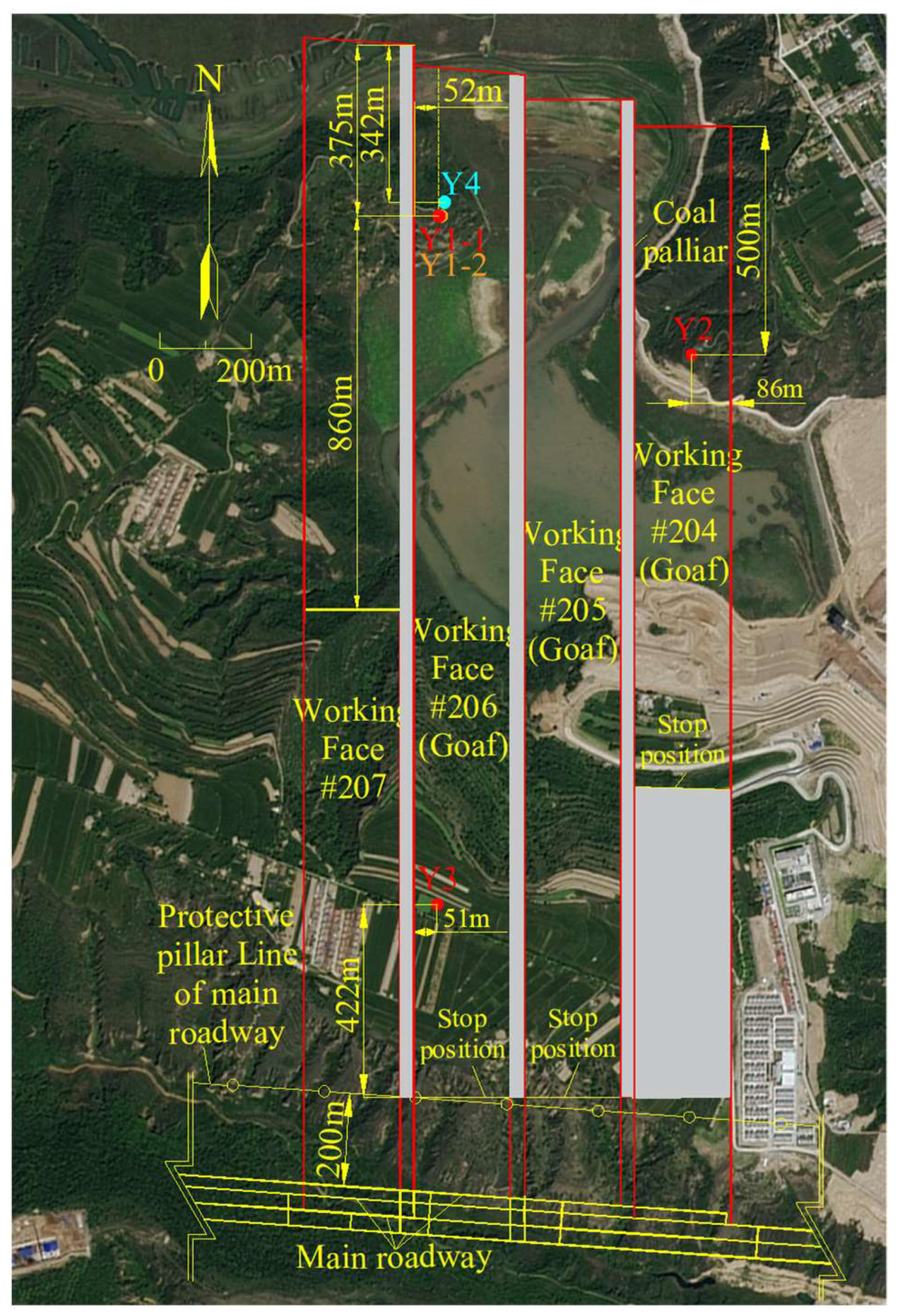
Based on the conditions of Panel #2 and surface terrain factors, five boreholes were drilled into the working faces of Panel #2, whose locations are shown in Figure 5. The aim was to gain an understanding of how mining-induced cracks evolved in Panel #2 as well as the mining-induced movement of the overburden above the goaf of Working Face #207. Y1-1, Y1-2, Y2, and Y3 are strata movement monitoring boreholes with MPBXs installed. The cracks inside the strata were first surveyed prior to the installation of the MPBXs. The Y4 borehole was used to measure the height of the water-conducting fracture zone (WCFZ) and it was drilled approximately 700 m ahead of Y1-1 in the direction of the advancement of Working Face #207. The cracks inside the strata were surveyed once more at this borehole and the degree of crack development in it was compared to that of Y1-1. The Y1-1, Y1-2, and Y4 boreholes laid above the goaf of Working Face #206, with Y1-1 and Y4 being 375 m and 342 m away from the opening cut of Working Face #207, respectively. Y1-2 and Y4 were separated from Y1-1 by 5 m and 33 m, respectively. Y2 was located above the goaf of Working Face #204, 500 m from the opening cut of Working Face #207. Y3 was located above the goaf of Working Face #206, 422 m from the terminal line of Working Face #207. The details of each borehole are shown in Table 1.

3.4. Monitoring Position in the Borehole

Since the goal of the study is to gain an understanding of the cracks and movement in the Luohe Formation UTHS, and to measure the height of the WCFZ at the goaf, MPBXs were first placed in the Luohe Formation strata to reveal the upper boundary of the WCFZ. The positions of the borehole MPBXs with respect to the working faces and stratigraphic column are shown in Figure 6. This is the first time the internal movement of the Luohe Formation UTHS has been monitored in the Binchang Mining Area and it is also the first time in situ monitoring has been performed in an area as large as a whole panel. Consequently, the monitoring methodology and results of this paper will serve as a valuable reference for future studies.
One MPBX was installed in the Y1-1 borehole, while two MPBXs were installed in the Y1-2 borehole. Based on a nomenclature with the smallest number being assigned to the deepest MPBX, the MPBX at a depth of 295 m from the opening of Y1-1 was named Y1-1-1#, while the MPBXs at depths of 200 m and 95 m from the opening of Y1-2 were named Y1-2-2# and Y1-2-3#, respectively.
Y2 was located above the goaf of Working Face #204 at the boundaries of the panel. This MPBX was meant to determine whether the stopping of Working Face #207 would induce movement in the strata around the boundaries of the panel. The position of Y2 was 636 m from the boundaries of Working Face #207 and the strata movements at this borehole were monitored using both distributed fiber optic lines and an armored cable with MPBXs. The fiber optic point sensors were installed at depths of 130, 260, and 330 m. The MPBX was installed at a depth of 130 m. The drilling construction and monitoring system after installation are shown in Figure 7.

4. Results: Distribution of Internal Fractures in the UTHS

The comparison of fissures in the holes caused by the mining and monitoring of mining strata movement formed the during mining provide key data for analyzing the law of strata movement.

4.1. Development of Water-Conducting Fractures

Water-conducting fractures are usually assumed to be stratum-penetrating fractures [36,37] and it is generally thought that all of the strata within a WCFZ are fractured. Therefore, by measuring the height of the WCFZ, one may determine the degree of fracturing in the UTHS.
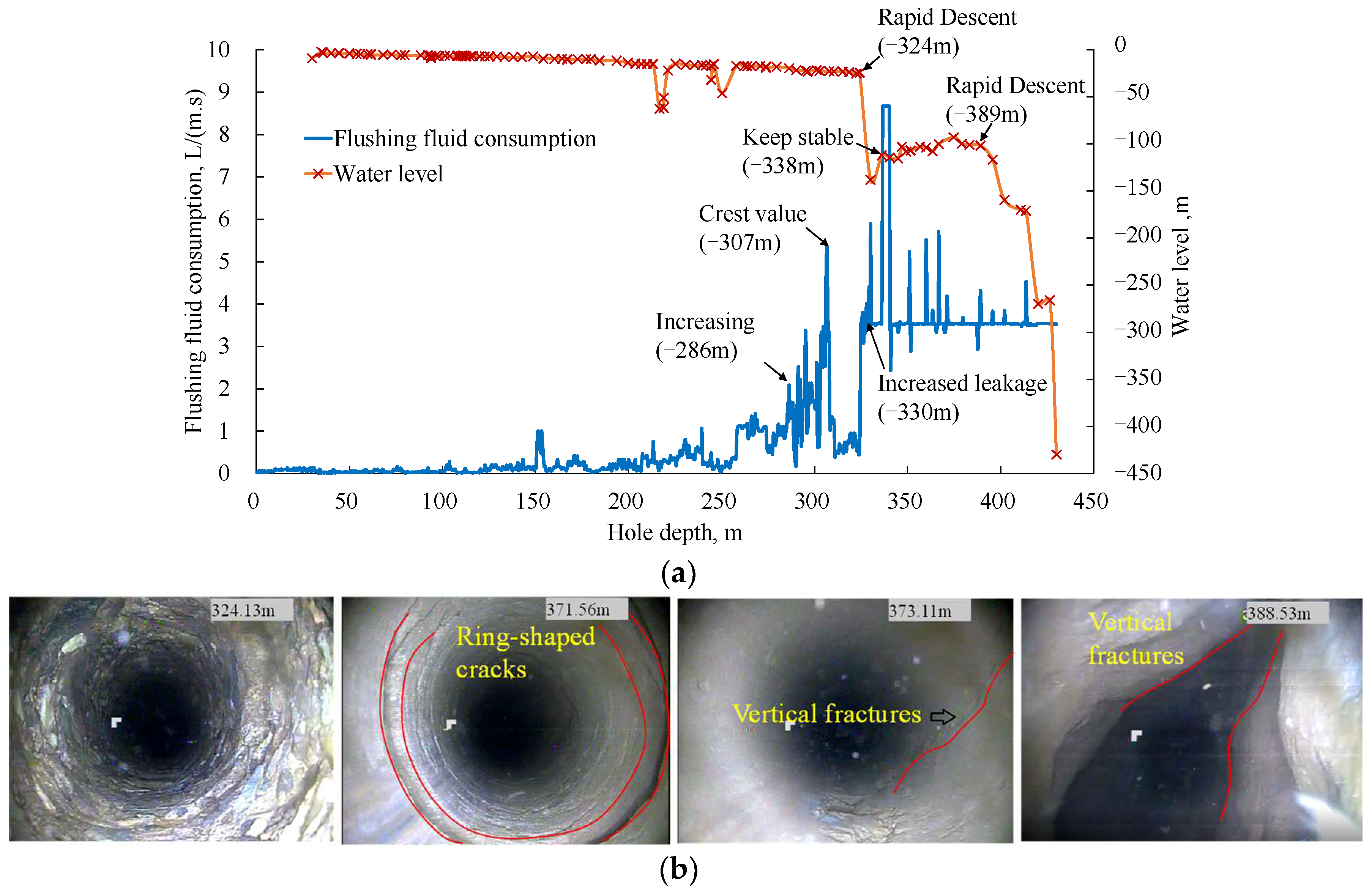
The Y1-1 borehole was located above the goaf of Working Face #206 in Panel #2, its elevation being +891.7 m. The roof of the coal seam had an elevation of +377.6 m and a buried depth of 514.1 m, and the thickness of the seam was 21.4 m. The actual extraction height of the working face was 7.5 m. After the boreholes were drilled, the cracks inside the boreholes were surveyed using peepholes before Working Face #207 was mined. It was found that many ring-shaped cracks were present from 292 to 337 m, approximately 50 m above the lower boundary of the Luohe Formation (see Figure 8b). At depths greater than 371 m, vertical cracks and irregular deformation began to appear in the walls of the boreholes and the fractures also became significantly larger. The changes in the drilling fluid loss and water level with depth are shown in Figure 8a. At 324 m, when the borehole reached the coarse conglomerate stratum, drilling fluid loss increased sharply while the water level plummeted due to the high permeability of this stratum. However, no vertical fractures were observed through the peephole and the water level in the borehole remained at a relatively high level, as it did not drain out completely. Vertical fractures began to appear at depths greater than 371.6 m and the water level began to decrease significantly from 389 m onwards. Therefore, the top of the WCFZ was located at a depth 371.6 m and the height of the WCFZ was 140.2 m above the coal seam.
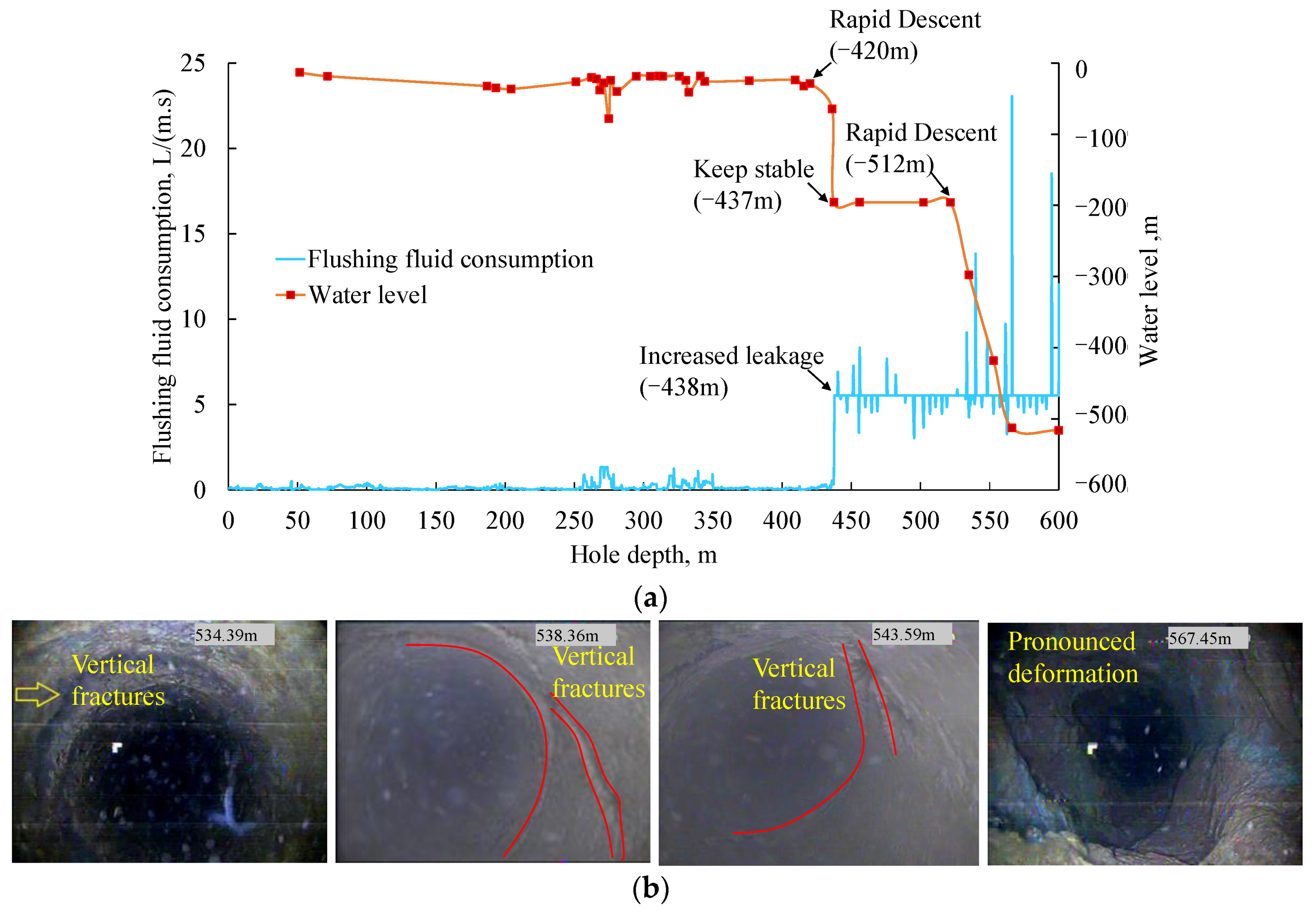
The Y3 borehole was drilled above the goaf of Working Face #206 at an elevation of 1069.6 m and depth of 600 m. The elevation of the roof of the corresponding coal seam was +386.9 m and its buried depth was 628.7 m. The actual extraction height was 9.0 m. After the borehole was drilled, a peephole survey was performed inside the bore prior to the mining of Working Face #207. It was found that the walls of the borehole were fully intact (with no fractures) from 521.7 to 534.4 m. Cracks began to appear from 534.4 to 564.2 m and the deformations of the borehole became more pronounced with increasing depth, as shown in Figure 9. Based on these changes, it is likely that the upper boundary of the WCFZ was at a depth of 534.4 m and the height of it at Y3 was 148.3 m above the coal seam.
Based on the WCFZ height measurements, after Working Face #206 was mined, the fracture in the roof of the coal seam reached the lower part of the Yijun Formation and a number of ring-shaped cracks formed at the bottom of the Luohe Formation. Consequently, the Luohe Formation UTHS cracked due to mining-induced disturbances and was not fully intact. Since significant vertical fractures had yet to be observed in the Luohe Formation, the damage in it was mainly horizontal and layer-like in nature, and a penetrating fracture had yet to form.

4.2. Mining-Induced Crack Closure and Migration

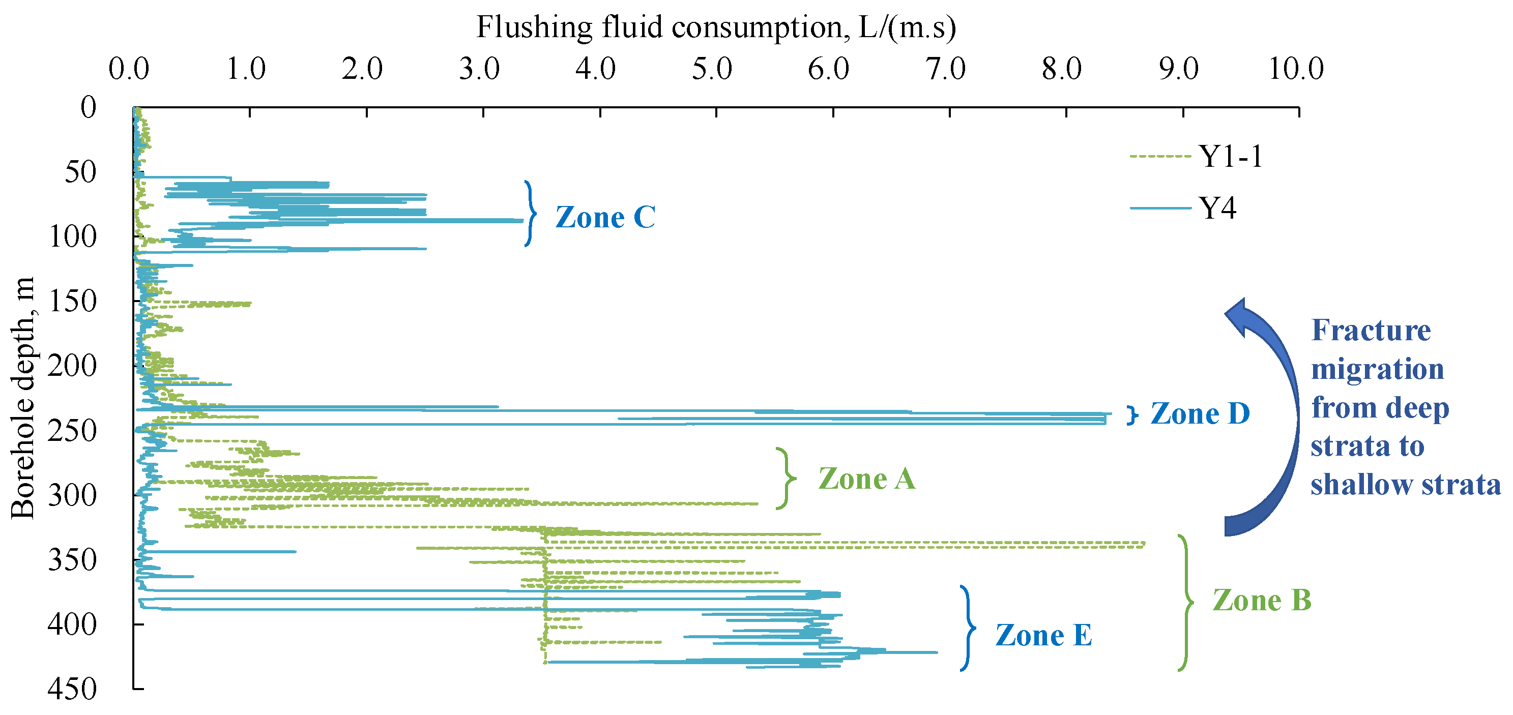
When Working Face #207 advanced 700 m beyond Y1-1 (4 June 2018), the Y4 borehole was drilled 33 m from Y1-1, above the goaf of Working Face #206. The design depth of Y4 was reached when Working Face #207 advanced 860 m beyond Y1-1 (31 July 2018). Y1-1 and Y4 were quite close to each other and the state of Working Face #207 (whether it had been mined or not) was the main difference between these boreholes. To explain the distribution of the internal cracks in the strata, Y1-1 and Y4 were compared in terms of drilling fluid losses during their drilling processes, as shown in Figure 10.
Before Working Face #207 was mined, the drilling fluid losses of Y1-1 were most significant in Zone A and Zone B, the losses occurring mainly at the bottom of the borehole. After Working Face #207 was mined, drilling fluid losses began to increase when the borehole reached Zone C (depth of 50–109 m). The rate of the drilling fluid loss suddenly increased significantly when the borehole reached Zone D at a depth of 231–245 m but decreased rapidly after this point. When it reached Zone E (depth of 374 m and beyond) in the Y4 borehole, the rate of the drilling fluid loss increased with increasing depth. Based on the drilling fluid losses of Y4 and Y1-1, it may be deduced that the cracks which were originally located in the deep zone (Zone A and B) had migrated towards the shallow zone (Zone C and D) after Working Face #207 was mined. The locations of the internal cracks in the boreholes were directly observed via peephole surveys and the distribution of fractures in the boreholes is shown in Figure 11.
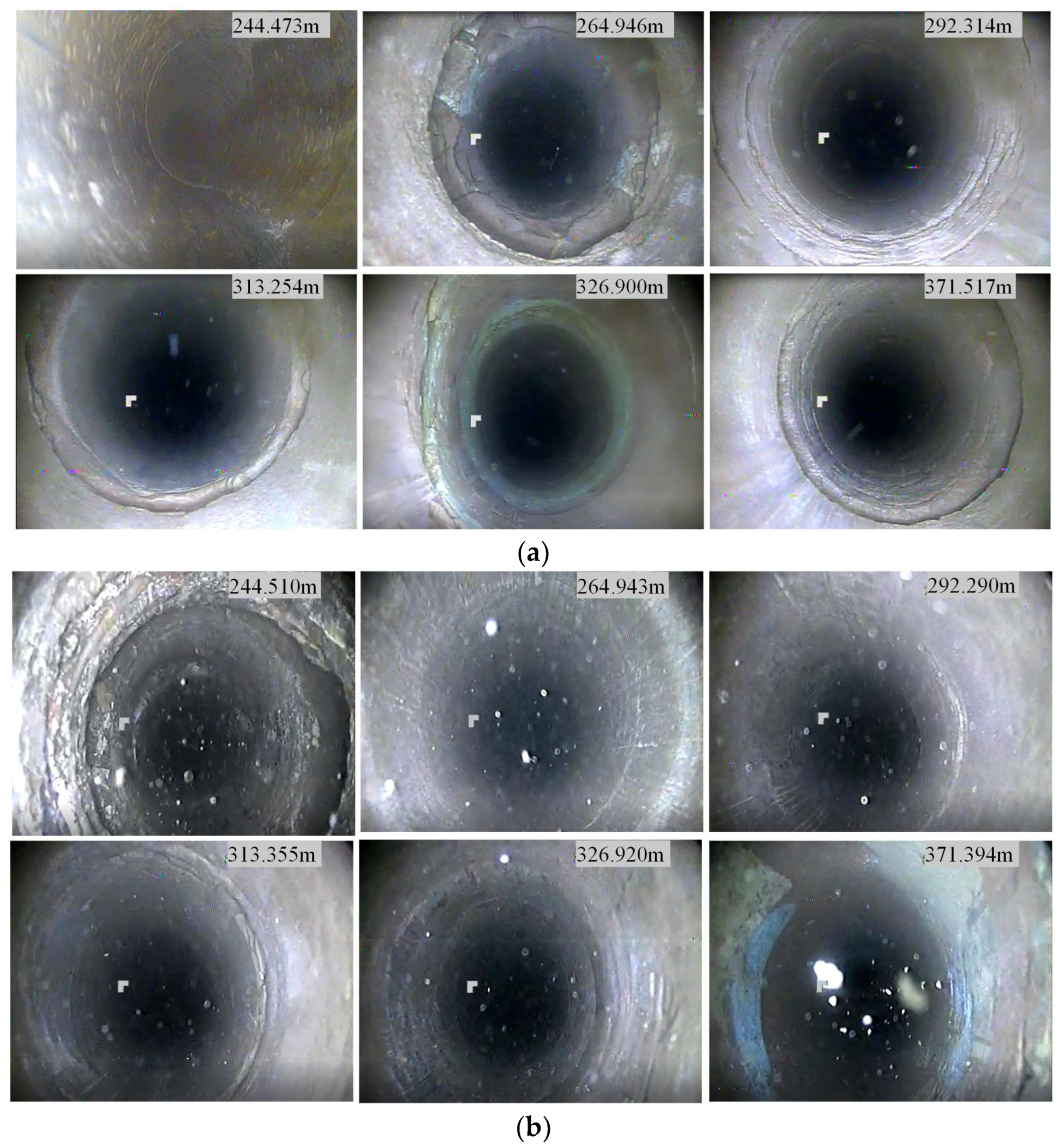
Based on the internal cracks of Y1-1 (Figure 11a), before Working Face #207 was mined, most of the 3–4 cm thick ring-like cracks were located at borehole depths of 256.90–313.25 m or 24.8–81 m above the lower boundary of the Luohe Formation. Very few thick, ring-like cracks were observed from 313.25 to 371.52 m. The Y4 borehole was used to probe the internal cracks of the strata after Working Face #207 advanced 860 m beyond Y1-1, as shown in Figure 11b. In the results, it can be seen that the ring-like cracks were most commonly found at depths of 236.92–281.03 m or 57–101 m above the lower boundary of the Luohe Formation. The cracks at all other depths were very small. After Working Face #207 advanced far beyond the borehole, the crack distribution of the strata shifted upwards and the lateral fractures inside the strata became thinner.
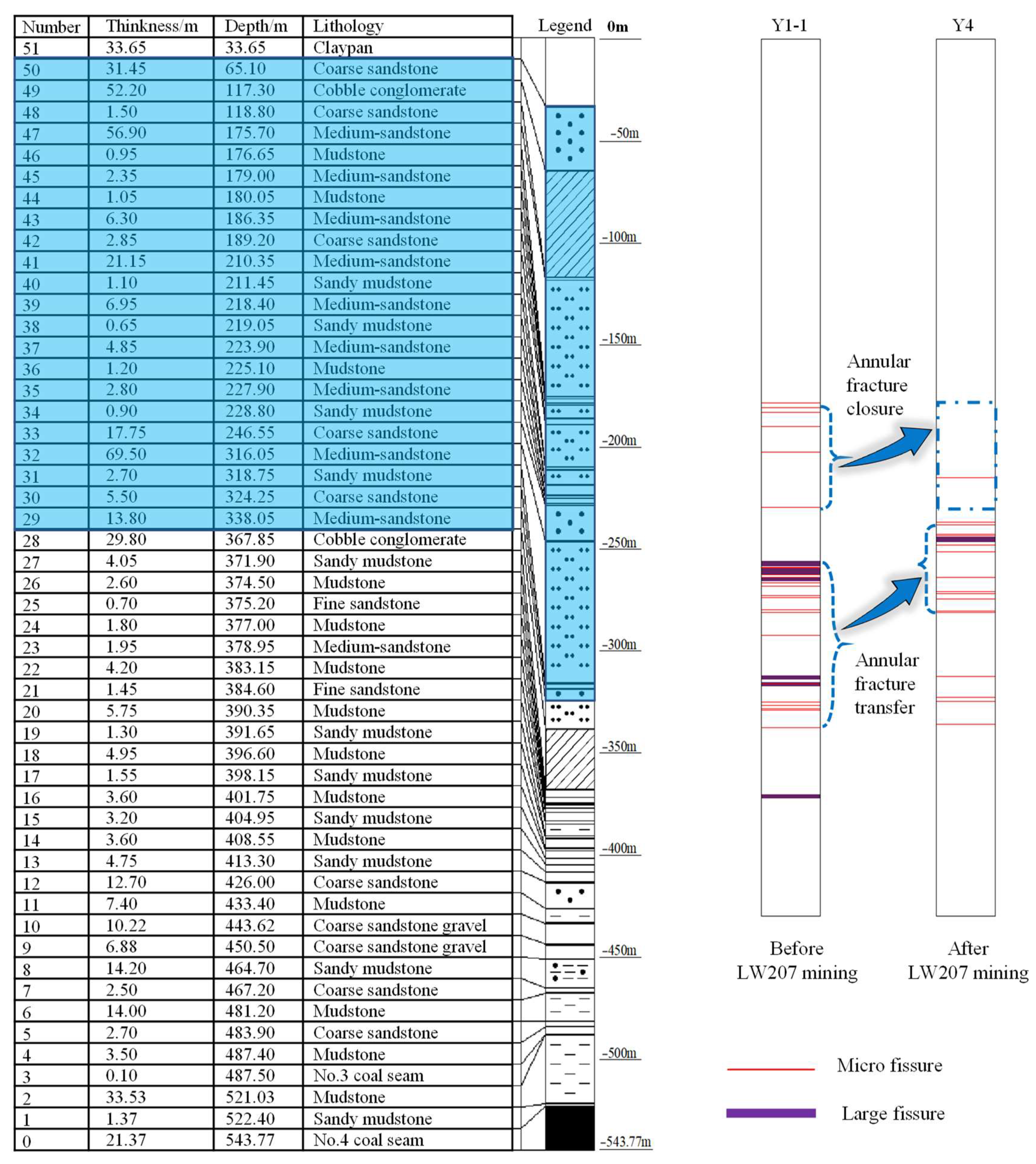
The cracks that were observed in Y4 were then mapped to those in Y1-1 and the stratigraphic distribution of these cracks is shown in Figure 12. It can be seen that the Y1-1 borehole, which laid above the goaf of Working Face #206, contained a large number of ring-shaped lateral fractures before Working Face #207 was mined. Most of these fractures were located between borehole depths of 250–340 m. The nearby Y4 borehole, which was also above the goaf of Working Face #206 and was drilled after Working Face #207 was mined, had a smaller number of ring-shaped fractures compared to Y1-1 and a significantly lower number of large ring-shaped fractures. Furthermore, the area where the fractures were most abundant had migrated towards shallow strata. Therefore, the mining-induced strata movement in this area had caused crack closure in the lower parts of the Luohe Formation, which reduced drilling fluid losses.
Based on the aforementioned results, the Luohe Formation UTHS was not completely stable while Working Face #207 was being mined, nor were large parts of these strata “dangling” above the goaf, as the fractures inside the boreholes were clearly migrating towards shallower strata. Therefore, the Luohe Formation UTHS, which had cracked above the goaves, sank due to the mining-induced perturbations of Working Face #207.

5. Discussion: Behavior of Internal Strata Movement

During the mining of Working Face #207, the internal strata movement in the boreholes above Working Faces #206 and #204 was monitored. The collected data were then used to analyze the behavior of the internal strata movement.

5.1. Data from Boreholes above the Goaf of Working Face #206

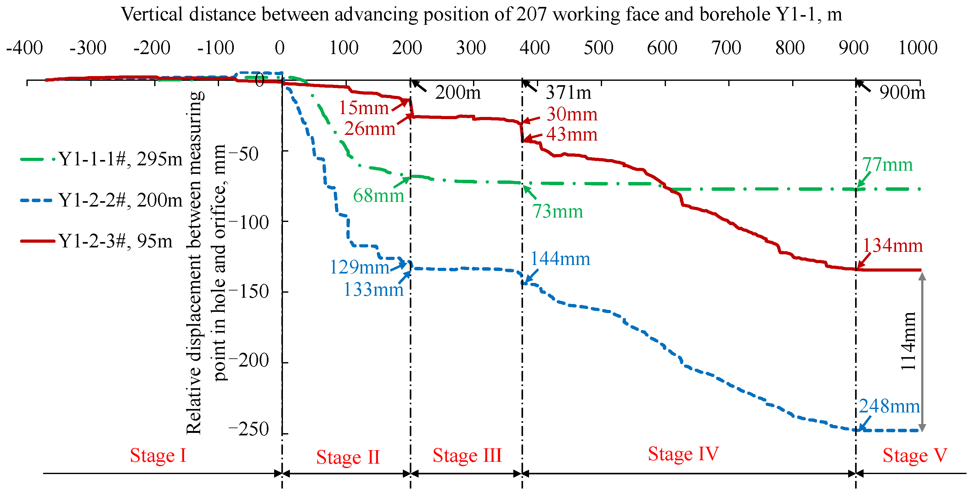
Figure 13 describes how the relative displacements of the measuring points in Y1-1 and Y1-2 with respect to their borehole openings changed with the advancement of Working Face #207. The horizontal axis is the vertical distance between the location of Working Face #207 and the borehole, while the vertical axis is the change in relative displacement between the measuring point inside the borehole and the opening of it. The change in relative displacement is 0 at the beginning (when the MPBXs were first installed); a positive value indicates that the distance of the measuring point from the opening increased (i.e., the strata was sinking) and a negative value indicates that this distance decreased (i.e., the opening of the borehole was subsiding due to strata compression).
The measuring points inside the boreholes moved significantly relative to their borehole openings when Working Face #207 was being mined. Stratum movement can be divided into five distinct stages.
Stage I: Before Working Face #207 was mined up to the boreholes, all of the MPBXs retracted slightly towards the surface by up to 5.5 mm. This was indicative of weak mining-induced strata compression ahead of the working face in the strata between the MPBXs and the surface.
Stage II: After Working Face #207 had been advanced beyond the boreholes, all of the measuring points rapidly subsided relative to their borehole openings. Y1-2-2# showed the largest movement, followed by Y1-1-1#. The Y1-2-3# MPBX, which had the shallowest buried depth, had the smallest motion. The motion of Y1-2-2# and Y1-2-3# reached 129 mm and 15 mm, with the difference between them being 114 mm when Working Face #207 advanced 200 m beyond the boreholes. Y1-2-2# and Y1-2-3# suddenly subsided after this point and the difference between their motion became 107 mm. Consequently, the internal strata movement was highly disharmonic when Working Face #207 advanced beyond the boreholes by a certain distance, which could easily create strata fractures.
Stage III: When Working Face #207 advanced from 200 to 371 m beyond the boreholes, the MPBXs were stable relative to their openings, which indicates that the strata were moving synchronously, with the difference between Y1-2-2# and Y1-2-3# being 114 mm (144 mm subtracts 30 mm).
Stage IV: After Working Face #207 advanced 371 m beyond the boreholes, Y1-2-2# and Y1-2-3# started to exhibit significant motion relative to the surface. The displacement of Y1-2-3# increased from 30 to 43 mm, which demonstrated that the shallower strata had moved significantly. Y1-2-2# and Y1-2-3# continued to show significant motion (due to the movements of the shallow strata) until Working Face #207 advanced 900 m beyond the boreholes.
Stage V: After Working Face #207 advanced 900 m beyond the boreholes, the MPBXs stabilized and stopped moving, indicating that the strata movement had completely stopped. The final displacements of Y1-1-1#, Y1-2-2#, and Y1-2-3# relative to the surface were 77, 248, and 134 mm, respectively, and the difference between Y1-2-2# and Y1-2-3# was still 114 mm.
As the difference between the displacements of Y1-2-2# and Y1-2-3# always stayed within 107–114 mm after Working Face #207 had advanced 200 m beyond the boreholes, it was likely that the UTHS was, as a whole, moving synchronously during these stages.
Since the Y1-1 and Y1-2 boreholes were only separated by a linear distance of 5 m, the fracture and strata movement data from these boreholes were comparable to each other, as the strata fractures and movement that occurred in one borehole should also have affected the other. Figure 13 shows the cumulative displacement of each measuring point relative to their borehole openings; by calculating the difference in displacement between two measuring points, one may determine the strata movement that occurred between them. Figure 14 reflects the generation or closure of internal fractures in the strata between the measuring points of MPBX. A positive value indicates that the total number of cracks increased since the installation of the MPBX, while a negative value indicates that the total number of cracks decreased; the absolute value reflects the magnitude of the change.
Based on Figure 14, it can be seen that the mining of Working Face #207 caused the cracks between the measuring points to evolve in two distinct stages: a rapid-change stage and a stable stage. The rapid-change stage occurred during the advancement of the working face from the boreholes up to 200 m beyond them. Crack closure occurred in the cracks between Y1-1-1# and Y1-2-2#, and the closure that occurred during this stage was 61 mm. Crack opening occurred between Y1-2-2# and Y1-2-3# (114 mm by the time the stable stage had arrived). These results indicate that new cracks or crack expansion occurred in the strata at borehole depths of 95–200 m, whereas partial crack closure occurred in the strata at borehole depths of 200–295 m. This is consistent with the results that were obtained by comparing the internal cracks of the Y1-1 and Y4 boreholes, that is, the original cracks closed and migrated towards shallower strata after the mining of Working Face #207. The closure of these cracks also explains why drilling fluid loss at borehole depths of 250–320 m was lower in Y4 than in Y1-1.
The subsidence of the borehole openings was also monitored by GPS during the mining of Working Face #207. The surface subsidence curves of the borehole openings are shown in Figure 15. During the mining of Working Face #207, the surface near the Y1-1 borehole subsided by 1380 mm, while the Y1-1-1#, Y1-2-2#, and Y1-2-3# points subsided by 1457, 1633, and 1523 mm, respectively.
By performing a borehole-based in situ survey of strata fractures, comparing the distribution of cracks in the UTHS before and after the mining of Working Face #207, and monitoring both the internal strata movement and surface displacements of this region, we determined that the Luohe Formation UTHS was not poised in a suspended and unmoving state during the mining of Working Face #207. Therefore, it was unlikely that a large and sudden break would occur in the UTHS during the mining of Working Face #207.

5.2. Data from the Borehole above the Goaf of Working Face #204

Figure 16 describes how the micro-strain in the fiber optic lines in Y2 changed with the advancement of Working Face #207. In the legend, a negative value is the distance before the working face reached the borehole, while a positive value is the advancement of the working face beyond the borehole. Positive strains are indicative of extension, while negative values are indicative of compression (relative to the original length). The data in this figure show that the changes in the length of the fiber optics typically ranged from −500 to 500 με. No significant changes in strain were observed at any stratum. Consequently, the mining of Working Face #207 only had a very small effect on the boundaries of the panel. The measuring point that was buried at a depth of 130 m in Y2 also did not exhibit any significant changes in displacement. These results show that the strata around the boundaries of the panel did not exhibit any significant internal movement or deformation, and the mining of Working Face #207 did not affect the overburden of Working Face #204. This was because the strata in the periphery of the panel had already stabilized.

6. Microseismic Monitoring at Working Face #207

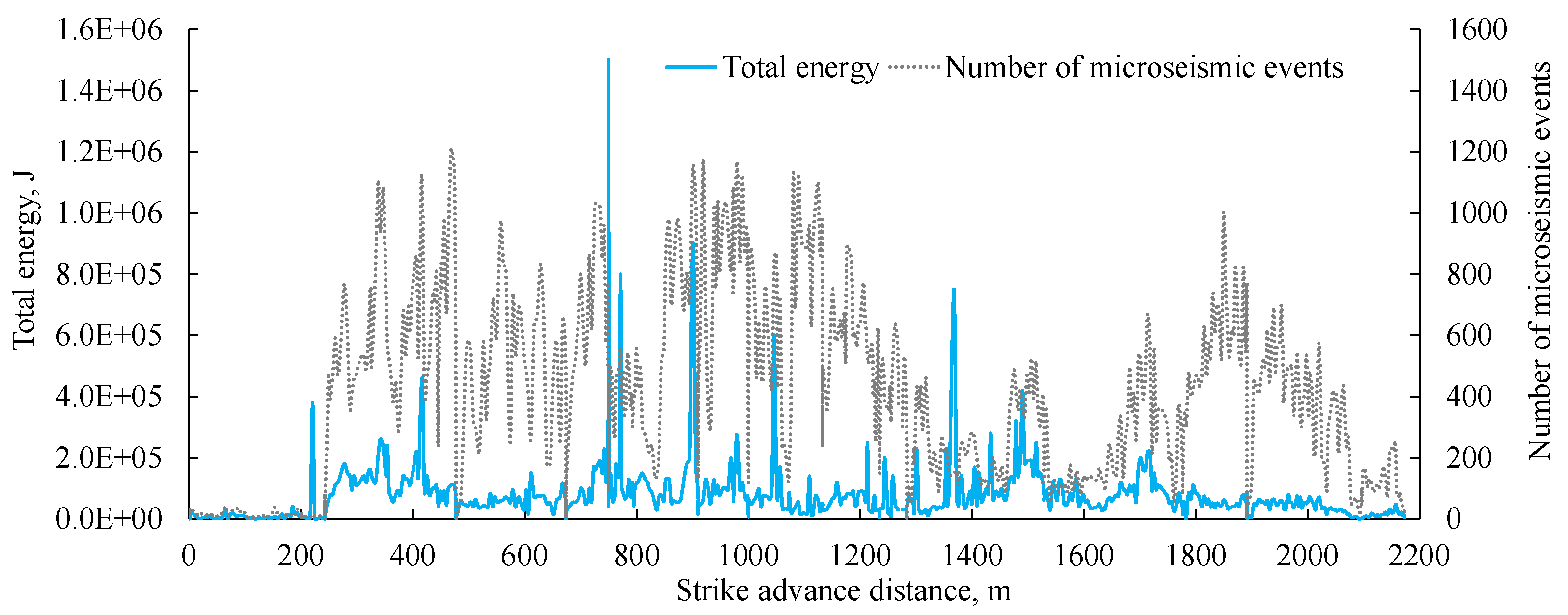
Since intense MIP events occurred during the mining of Working Faces #205 and #206, microseismic monitoring was performed during the mining of Working Face #207. The results of the microseismic monitoring during the mining of Working Face #207 are shown in Figure 17. The horizontal axis represents the advancement of the working face, while the vertical axis represents the total energy of the microseismic events that occurred at Working Face #207 as well as their number. Although a few high-energy events did occur during the mining of Working Face #207, no long-distance MIP events occurred. As a whole, the microseismic events were frequent but weak.
Based on these results and the previously described internal strata movement, we can conclude that the Luohe Formation UTHS had already fractured before Working Face #207 was mined. Furthermore, the Luohe Formation UTHS subsided continuously during the mining of Working Face #207 rather than was “dangling” above the goaf. Consequently, there was no risk of a large and sudden break in the UTHS. The results of this paper have provided useful information for assessing the risk of mining Working Face #207, the aforementioned conclusions of which have been validated during the mining of this working face. The knowledge gained in this paper has ultimately allowed Working Face #207 to be mined safely.

7. Conclusions

(1)
Armored cables with MPBXs and fiber optic lines were used together for the first time over a panel-wide area and at great depths in the Luohe Formation UTHS of the Binchang Mining Area to monitor the evolution of mining-induced cracks in Panel #2 in the Tingnan Coal Mine, which serves as a reference for future endeavors to measure overburden movement.
(2)
The Luohe Formation UTHS had already fractured before Working Face #207 was mined, as ring-shaped lateral fractures were observed 24.8–81 m above the lower boundary of the Luohe Formation. However, no vertical penetrating fractures were observed. The height of the WCFZ in Working Face #206 was 140.2 m and 148.3 m, with a mining height of 7.5 m and 9.0 m. Based on the monitoring of the internal strata movement, the peephole-based crack surveys, and the comparison of drilling fluid losses in each borehole, it was determined that crack closure occurred in the middle and lower parts of the Luohe Formation during the mining of Working Face #207. These fractures also migrated towards shallower strata. As the Luohe Formation continuously subsided during the mining of Working Face #207, there was no risk that a large and sudden break would occur in some “dangling” part of the Luohe Formation UTHS.
(3)
The results and conclusions drawn from the monitoring of internal strata movement in the Luohe Formation UTHS serve as important references for assessing the risk of mining Working Face #207. The final displacements of Y1-1-1#, Y1-2-2#, and Y1-2-3# relative to the surface were 77, 248, and 134 mm, which were very small relative to the surface subsidence. The Luohe Formation UTHS was not poised in a suspended and unmoving state during the mining of Working Face #207. Therefore, it was unlikely that a large and sudden break would occur in the UTHS during the mining of Working Face #207. The conclusions of this paper have also been validated by the microseismic monitoring that was performed during the mining of Working Face #207.

8. Highlights

(1)
This paper focused on Panel #2 at the Tingnan Coal Mine in the Binchang mining area.
(2)
The internal strata motion of the overburden and its fractures were monitored in situ.
(3)
Fiber optics with multipoint borehole extensometers were installed in the boreholes.
(4)
The paper provides important data for safer mining operations at Working Face #207.

Author Contributions

Conceptualization, J.X. (Jialin Xu) and X.W.; methodology, J.X. (Jianlin Xie) and W.Z.; investigation, H.H. and Z.T.; resources, Z.T.; data curation, J.X. (Jingmin Xu); writing—original draft preparation, X.W.; writing—review and editing, J.X. (Jialin Xu) and X.W.; project administration and funding acquisition, W.Z. All authors have read and agreed to the published version of the manuscript.

Funding

This work was supported by the National Natural Science Foundation of China (52074265 and 51874175) and the Tiandi Huatai Science and Technology Innovation Fund (TDHTKY2021003).

Acknowledgments

We extend our sincere thanks to the related engineers at the Tingnan coal mine for their substantial support and help in the field measurement and engineering detection.

Conflicts of Interest

The authors declare no conflict of interest.

References

  1. Fan, K.F.; Li, W.P.; Wang, Q.Q.; Liu, S.L.; Xue, S.; Xie, C.Y.; Wang, Z.K. Formation mechanism and prediction method of water inrush from separated layers within coal seam mining: A case study in the Shilawusu mining area, China. Eng. Fail. Anal. 2019, 103, 158–172. [Google Scholar] [CrossRef]
  2. He, J.H.; Li, W.P.; Qiao, W.; Yang, Z.; Wang, Q.Q. Analysis of key factors affecting water disaster in deep mining and establishment of a water disaster evaluation method suitable for different mining depths. Geofluids 2021, 2021, 9948763. [Google Scholar] [CrossRef]
  3. Jiang, Y.D.; Zhao, Y.X.; Wang, H.W.; Zhu, J. A review of mechanism and prevention technologies of coal bumps in China. J. Rock Mech. Geotech. 2017, 9, 180–194. [Google Scholar] [CrossRef]
  4. Shi, X.C.; Zhang, Y.; Lv, G.L. Water-preserved mining and exploitation of groundwater resources in yonglong-binchang mining area. J. Min. Safe Eng. 2018, 35, 1241–1247. (In Chinese) [Google Scholar]
  5. Wang, G.F.; Gong, S.Y.; Dou, L.M.; Cai, W.; Yuan, X.Y.; Fan, C.J. Rockburst mechanism and control in coal seam with both syncline and hard strata. Saf. Sci. 2019, 115, 320–328. [Google Scholar] [CrossRef]
  6. Lv, Y.G.; Xiao, Q.H.; Cheng, J.L. Mechanism and prevention of water-sand inrush in soft rock with weakly abundant water: A case study in shanghai temple mining area. J. Chin. Coal Soc. 2019, 44, 3154–3163. (In Chinese) [Google Scholar]
  7. Qiao, W.; Wang, Z.W.; Li, W.P.; Lv, Y.G.; Li, L.G.; Huang, Y.; He, J.H.; Li, X.Q.; Zhao, S.L.; Liu, M.N. Formation mechanism, disaster-causing mechanism and prevention technology of roof bed separation water disaster in coal mine. J. Chin. Coal Soc. 2021, 46, 507–522. (In Chinese) [Google Scholar]
  8. Mondal, D.; Roy, P.N.S.; Behera, P.K. Use of correlation fractal dimension signatures for understanding the overlying strata dynamics in longwall coal mines. Int. J. Rock Mech. Min. 2017, 91, 210–221. [Google Scholar] [CrossRef]
  9. Mondal, D.; Roy, P.N.S.; Kumar, M. Monitoring the strata behavior in the destressed zone of a shallow Indian longwall panel with hard sandstone cover using mine-microseismicity and borehole televiewer data. Eng Geol. 2020, 271, 105593. [Google Scholar] [CrossRef]
  10. Zhang, M.; Jiang, F.X.; Li, K.Q.; Wang, C.W.; Wu, X.G.; Gao, H.J.; Ji, S.H. Study of the compatible deformation and stability of the system of super thick strata and coal pillars. Chin. J. Rock Mech. Eng. 2017, 36, 326–334. (In Chinese) [Google Scholar]
  11. Wang, J.A.; Liu, H.; Ji, H.G. Study on fracture mechanism of overlying super-thick rock stratum in underground mining. Chin. J. Rock Mech. Eng. 2009, 28, 2815–2823. (In Chinese) [Google Scholar]
  12. Xuan, D.Y.; Xu, J.L.; Zhu, W.B. Dynamic disaster control under a massive igneous sill by grouting from surface boreholes. Int. J. Rock Mech. Min. 2014, 71, 176–187. [Google Scholar] [CrossRef]
  13. Xuan, D.Y.; Wang, B.L.; Xu, J.L. A shared borehole approach for coal-bed methane drainage and ground stabilization with grouting. Int. J. Rock Mech. Min. 2016, 86, 235–244. [Google Scholar] [CrossRef]
  14. Han, H.; Xu, J.; Wang, X.; Xie, J.; Xing, Y. Surface subsidence prediction method for coal mines with ultrathick and hard stratum. Adv. Civ. Eng. 2019, 2019, 3714381. [Google Scholar] [CrossRef]
  15. Ning, J.G.; Wang, J.; Jiang, L.S.; Jiang, N.; Liu, X.S.; Jiang, J.Q. Fracture analysis of double-layer hard and thick roof and the controlling effect on strata behavior: A case study. Eng. Fail Anal. 2017, 81, 117–134. [Google Scholar] [CrossRef]
  16. Scott, A.A.; Nicholas, J.L. Rockfill embankment settlement: Sugarloaf Mountain bridge abutment and hoover dam bypass (US-93). Transport. Res. Rec. 2016, 1, 3–12. [Google Scholar]
  17. Avramov, I.; Velkov, T.; Garko, I.; Stefanov, D.; Georgakiev, I. Using large-scale geotechnical modelling to solve mining tasks at a gold-copper mine. In Proceedings of the International European Rock Mechanics Symposium (EUROCK), Saint Petersburg, Russia, 22–26 May 2018; pp. 465–470. [Google Scholar]
  18. Barton, N.; Pandey, S.K. Numerical modelling of two stopping methods in two Indian mines using degradation of C and mobilization of Φ based on Q-parameters. Int. J. Rock Mech. Min. 2011, 48, 1095–1112. [Google Scholar] [CrossRef]
  19. Yeung, M.R.; Blair, S.C. Analysis of large block test data using the DDA method. In Proceedings of the 3rd International Conference on Analysis of Discontinuous Deformation, Vail, CO, USA, 3–4 June 1999; pp. 141–150. [Google Scholar]
  20. Sinha, S.; Walton, G. Integration of three-dimensional continuum model and two-dimensional bonded block model for studying the damage process in a granite pillar at the Creighton Mine, Sudbury, Canada. J. Rock. Mech. Geotech. 2021, 13, 275–288. [Google Scholar] [CrossRef]
  21. Abdellah, W.; Raju, G.D.; Mitri, H.S.; Thibodeau, D. Stability of underground mine development intersections during the life of a mine plan. Int. J. Rock Mech. Min. 2014, 72, 173–181. [Google Scholar] [CrossRef]
  22. Ingram, D.K.; Trevits, M.A.; Jeran, P.W. Overburden failure due to longwall mining. In Proceedings of the 1st North American Rock Mechanics Symposium, Austin, TX, USA, 1–3 June 1994; pp. 1025–1032. [Google Scholar]
  23. Zhu, W.B.; Xu, J.L.; Shi, X.S.; Wang, X.Z.; Liu, W.T. Research on influence of overburden primary key stratum movement on surface subsidence with in-situ drilling test. Chin. J. Rock Mech. Eng. 2009, 28, 403–409. (In Chinese) [Google Scholar]
  24. Yang, J.Z.; Hu, B.W.; Wang, Z.R. Study on distribution characteristics of collapse zone, fissure zone and curved subsidence zone and layered settlement of overburden on 8.8 m super-large mining height coal mining face. Coal Sci. Tech. 2020, 48, 42–48. (In Chinese) [Google Scholar]
  25. Holla, L.; Buizen, M. The ground movement, strata fracturing and changes in permeability due to deep longwall mining. Int. J. Rock Mech. Min. 1991, 28, 207–217. [Google Scholar] [CrossRef]
  26. Kuang, T.J.; Li, Z.; Zhu, W.B.; Xie, J.L.; Ju, J.F.; Liu, J.R.; Xu, J.M. The impact of key strata movement on ground pressure behaviour in the Datong coalfield. Int. J. Rock Mech. Min. 2019, 119, 193–204. [Google Scholar] [CrossRef]
  27. Yu, B.; Gao, R.; Kuang, T.J.; Huo, B.J.; Meng, X.B. Engineering study on fracturing high-level hard rock strata by ground hydraulic action. Tunn. Undergr. Sp. Tech. 2019, 86, 156–164. [Google Scholar] [CrossRef]
  28. Yu, B.; Zhao, J.; Kuang, T.J.; Meng, X.B. In situ investigations into overburden failures of a super-thick coal seam for longwall top coal caving. Int. J. Rock Mech. Min. 2015, 78, 155–162. [Google Scholar] [CrossRef]
  29. Yu, B.; Zhao, J.; Xiao, H.T. Case study on overburden fracturing during longwall top coal caving using microseismic monitoring. Rock Mech. Rock Eng. 2017, 50, 507–511. [Google Scholar] [CrossRef]
  30. Cheng, G.W.; Ma, T.H.; Tang, C.A.; Liu, H.Y.; Wang, S.J. A zoning model for coal mining induced strata movement based on micro seismic monitoring. Int. J. Rock Mech. Min. 2017, 94, 123–138. [Google Scholar] [CrossRef]
  31. Liu, Y.; Li, W.P.; He, J.H.; Liu, S.W.; Cai, L.Y.; Cheng, G. Application of brillouin optical time domain reflectometry to dynamic monitoring of overburden deformation and failure caused by underground mining. Int. J. Rock Mech. Min. 2018, 106, 133–143. [Google Scholar] [CrossRef]
  32. Cappa, F.; Guglielmi, Y.; Gaffet, S.; Lançon, H.; Lamarque, I. Use of in situ fiber optic sensors to characterize highly heterogeneous elastic displacement fields in fractured rocks. Int. J. Rock Mech. Min. 2006, 43, 647–654. [Google Scholar] [CrossRef]
  33. Xie, J.L.; Xu, J.L. Effect of key stratum on the mining abutment pressure of a coal seam. Geosci. J. 2017, 21, 267–276. [Google Scholar] [CrossRef]
  34. Han, H.K.; Xu, J.L.; Wang, X.Z.; Xie, J.L.; Xing, Y.T. Method to calculate working surface abutment pressure based on key strata theory. Adv. Civ. Eng. 2019, 2019, 767832. [Google Scholar] [CrossRef] [Green Version]
  35. Guo, G.L.; Zha, J.F. Mining Subsidence; China University of Mining & Technology Press: Xuzhou, China, 2020. [Google Scholar]
  36. Xu, J.L.; Zhu, W.B.; Wang, X.Z. New method to predict the height of fractured water-conducting zone by location of key strata. J. Chin. Coal Soc. 2012, 37, 762–769. (In Chinese) [Google Scholar]
  37. He, C.C.; Lu, W.Y.; Zha, W.H. Evolution mechanism of interconnected vertical fractures in the overburden of longwall coal mining. Geofluids 2020, 2020, 8862517. [Google Scholar] [CrossRef]
Figure 1. Stratum comprehensive columnar sketch map.
Minerals 11 01157 g001
Figure 2. The layout of working faces and mining conditions in Panel #2.
Minerals 11 01157 g002
Figure 3. Method for detecting crack in borehole. (a) Method for monitoring drilling fluid loss and (b) camera system for peephole.
Minerals 11 01157 g003
Figure 4. Schematic representation of the monitoring system.
Minerals 11 01157 g004
Figure 5. Borehole location.
Minerals 11 01157 g005
Figure 6. Positions of the borehole MPBXs with respect to the stratigraphic column. (a) No.Y1-1 and No.Y1-2 borehole, and (b) No.Y2 borehole.
Minerals 11 01157 g006aMinerals 11 01157 g006b
Figure 7. Drilling construction and monitoring system after installation: (a) Drilling construction and (b) monitoring system.
Minerals 11 01157 g007
Figure 8. In situ detection result at No.Y1-1 borehole. (a) Flushing fluid and bore water level variation, and (b) borehole camera.
Minerals 11 01157 g008
Figure 9. In situ detection result at No. Y3 borehole. (a) Flushing fluid and bore water level variation, and (b) borehole camera.
Minerals 11 01157 g009
Figure 10. Comparison of flushing fluid leakage during the drilling process at No. Y1-1 and the Y4 borehole.
Minerals 11 01157 g010
Figure 11. Distribution of fractures in the boreholes: (a) No.Y1-1 borehole and (b) No.Y4 borehole.
Minerals 11 01157 g011
Figure 12. Statistics of the borehole fracture distribution horizon.
Minerals 11 01157 g012
Figure 13. Curves of the rock movement measuring points in the borehole.
Minerals 11 01157 g013
Figure 14. Variation of the difference value of two measuring points in the borehole with advancing.
Minerals 11 01157 g014
Figure 15. New subsidence caused by the mining of Working Face #207.
Minerals 11 01157 g015
Figure 16. Distributed optical fiber monitoring data in the Y2 borehole: (a) metal-based optical fiber; (b) 130m, Y2-3#; (c) 260 m, Y2-2#; and (d) 330 m, Y2-1#.
Minerals 11 01157 g016
Figure 17. Monitoring results of microseism in the mining process of Working Face #207.
Minerals 11 01157 g017
Table 1. Information on different boreholes.
Borehole No.Y1-1Y1-2Y2Y3Y4
Vertical distance between orifice and 207 cut/m375.0380.0676.61883.2342.0
Orifice elevation/m+891.7+891.6+927.6+1069.6+891.5
Depth/m431.2230.5480.0600.0430.0
Thickness of loess layer/m33.733.751.0187.030.0
Buried depth of bottom boundary of the Luohe Formation/m338.1338.1376.6509.0338.1
The depth of hole bottom exceeding the bottom boundary of the Luohe Formation/m93.1−107.6103.491.091.9
Buried depth of coal seam roof/m511.8511.8557.6682.7510.1
Distance between bottom boundary of the Luohe Formation and roof of coal seam/m173.7173.7181.0173.7172.0
Distance between hole bottom and coal seam roof/m80.6281.277.682.780.1
Publisher’s Note: MDPI stays neutral with regard to jurisdictional claims in published maps and institutional affiliations.