1. Introduction
With the depletion of shallow mineral resources, the mining operations are going deeper. Coal mining depths in many countries such as China, Germany, Poland, and Russia, have reached more than 1000 m deep [
1,
2]. In some cases, it is up to 1500 m deep [
1]. In China, about 53% of the estimated coal reserves are deeper than 1000 m. Hence, operational and research activities in deep coal mining are progressing rapidly [
2,
3,
4]. However, the experience in deep mining is limited [
5], leading to an increase in mining difficulty and risk associated with the high-stress regime.
There is currently no universally accepted definition of deep mining [
6]. Some researchers [
1] proposed that deep mining should be defined by the mechanical state characterized by geo-stress, mining-induced stress, and rock mechanical properties [
3]. However, the mining depth is commonly used to define deep mining [
1,
2,
3,
4,
5,
6,
7,
8]. The mines operated below 800 m in coal mining [
3] and 1000 m in metal mining [
1] are normally considered deep mining.
The complicated geo-mechanical conditions in deep mining present a great challenge for safe, efficient, and environmental-friendly mining. Xie et al. [
4] highlighted that the presence of high geo-stress, high geo-temperature, high pore pressure, high risk of rock and gas burst, high risk of spontaneous combustion, and complicated overburden strata pose safety concerns in deep mining. Further, interrelated dynamic interactions between rock, water, and gas caused by mining adds significant complexity to mine safety and production. Therefore, it is important to gain a clear and thorough understanding of site-specific strata deformation characteristics to implement effective measures to minimize geohazards during and after mining operations.
Coal burst is one of the principal hazards in deep mining. Its risk can be attributed to several factors. In general, rockburst is associated with high static and dynamic loadings [
9,
10]. The stress concentration in the abutment zones of excavations is the main element for static loading, whereas rock fracturing in overlying and underlying strata is the key source of dynamic loading. Increasing the depth of cover on mining activities and the associated complex local geology can significantly increase the coal burst risk. The properties of the coal being mined also impact the coal burst risk. The burst mechanism in different strengths of coal can be substantially different, suggesting that the same rockburst assessment method may not be applicable to all kinds of coal [
11].
The risk of coal burst can be mitigated by optimizing mine designs and extraction parameters. It is reported that a suitable pillar design can significantly reduce coal burst risks [
12,
13]. The longwall retreat speed also seems to impact the risk of coal burst [
14]. The root mechanism underlying these mine design measures are overburden deformation characteristics and their control on stress redistributions. Therefore, it is important to clearly understand overburden deformation processes in specific-mining conditions to develop effective controls for managing coal burst risk.
The overburden deformation and subsidence characteristics in deep mining have been reported to be different from shallow mining [
15,
16]. The depth of cover acts as one of the several key factors in determining the profile and characteristics of the overburdened strata movement in longwall mining [
17]. In addition to the depth of cover, several factors, including stratigraphy, panel dimensions, and thickness of overburden strata, control the development of overburden deformation and stress redistribution. Some researchers pointed out that the number and location of “key strata” [
18], defined as competent rock layers, influence the nature of the ground movement. The maximum ground subsidence has a negative logarithmic relation with the mining depth [
19,
20,
21,
22,
23]. The in-situ stress and tectonic features increase with the mining depth and cause high-stress concentration and intensive failure of the surrounding rock masses during longwall excavations. Thus, the likelihood of rockburst incidents and impact on roadway stability is higher in deep mining than in shallow mining [
1,
6,
7,
24,
25].
In this paper, a mine in China, operated at an approximate depth of 1000 m, is considered to study the effect of deep longwall mining on overburden strata movement, ground subsidence, and stress redistribution around the pillar region. The CSIRO in-house numerical code, COSFLOW [
26], is employed for this study. The effect of mining height, the nature of coal, panel width, and the presence of weak and strong strata on ground deformation characteristics are investigated in this paper. The aim of this study is to provide a qualitative characterization instead of quantitative.
2. Mine Condition
The coal mine studied in this paper is in the Northwest of Shaanxi Province, China. The mining depth is approximately 1000 m. The working seam is up to 14 m thick. A fully mechanized longwall top-coal caving technique is adopted in the mine. The extraction thickness is normally around 6 m in the longwall panels of Area 2. The overburden is dominated by sandstones and mudstones. A thick sandstone aquifer (200 m to 400 m) is located approximately 200 m above the working seam. In addition to coal burst risks in this deep mine condition, the abundant groundwater contained in the aquifer also poses a threat to mining safety, if not managed properly.
The mine has completed the extraction of Area 1, where the longwall panels were 112–150 m wide with varying lengths. A few coal burst incidents were reported during the mining of Area 1. In addition, the water inflow was up to several hundred cubic meters per hour, causing concerns about water inrush risks. Therefore, the mine needs to manage both the coal burst and water inrush risks in subsequent mining areas.
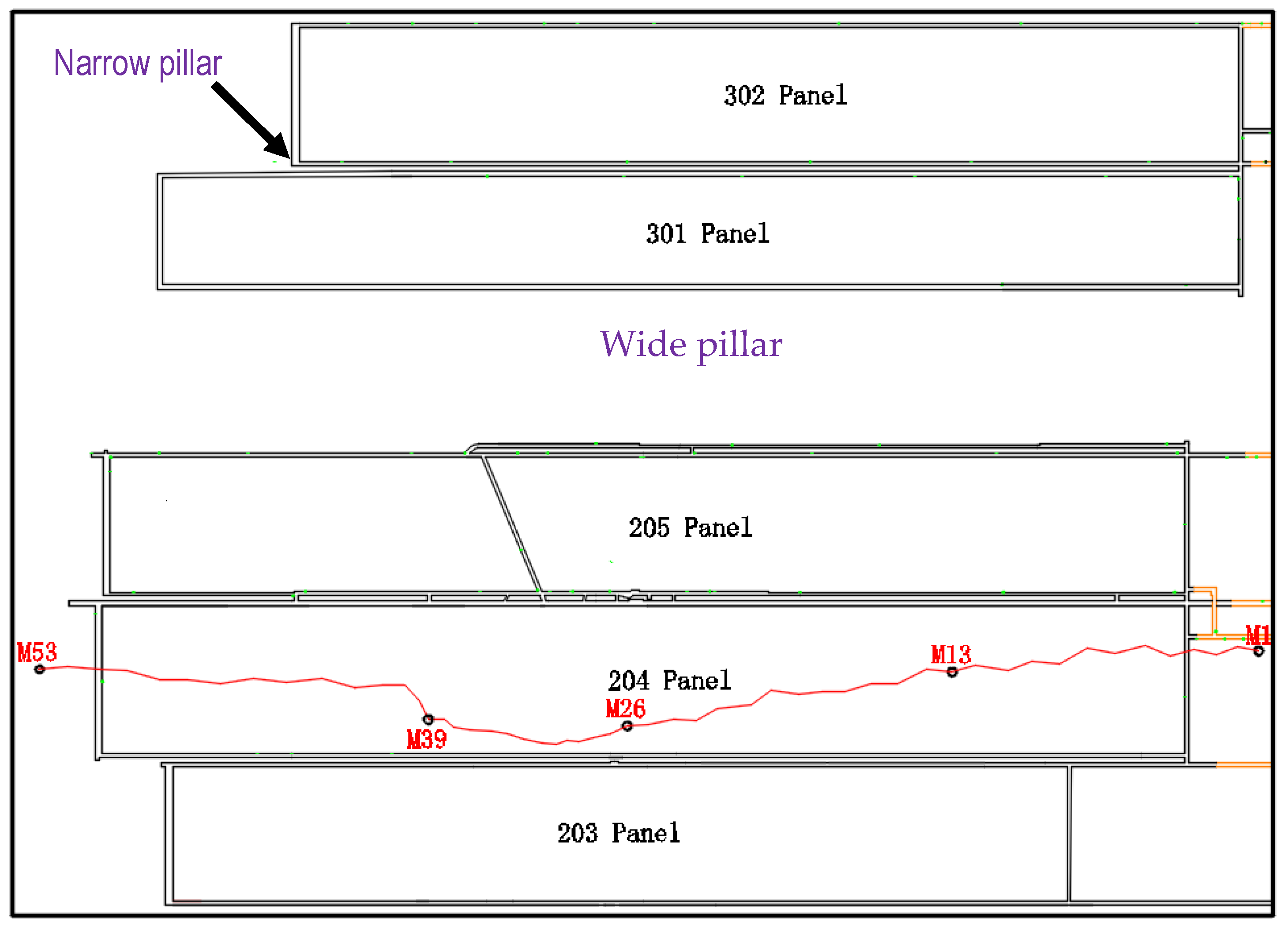
To reduce the risk of coal bursts and to avoid severe breakage of the thick aquifer, a special design of longwall panel layouts, with narrow pillars between the longwall panels are practiced for Area 2 and 3. These narrow pillars and longwall panels are then separated by a wide pillar.
Figure 1 shows the panel layouts in the study area. The current Area 3 of the mine plan is separated from Area 2 by a 200 m wide pillar. The longwall widths, ranging between 180 m and 220 m, are separated by 7 m wide rib pillars in a same mining area. The narrow pillars are meant to suffer failure under abutment stress to avoid stress concentration on the pillar and thereby minimize the risk of coal bursts hazards. The wide area pillar is designed to work as a load-bearing pillar to prevent an extensive breach of the thick aquifer and avoid water inrush risks.
3. Model Development and Calibration
An in-house finite element code, COSFLOW [
26], is employed in this numerical modelling study. COSFLOW is based on the Cosserat theory, which considers the joint effect on the load deformational behavior of layered rocks. Several studies have demonstrated the efficiency of this approach in simulating strata behaviors in a coal mining environment. More descriptions of COSFLOW and its applications in various mining-related issues can be found in [
27,
28].
3.1. Model Development
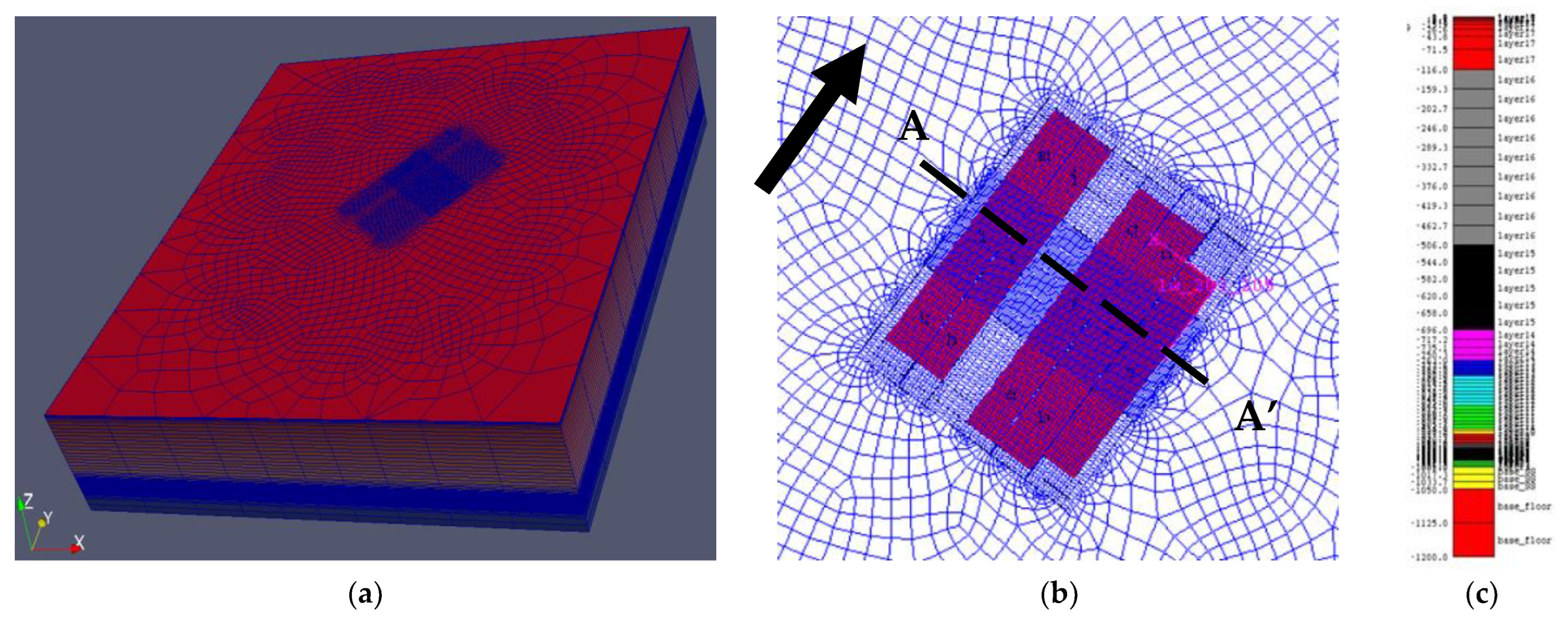
Longwall panels from 203 to 302 are included in the numerical modelling study. Longwall 203 provides a pre-mining condition for longwall 204, which is then used to calibrate the model with respect to the ground subsidence. A 3D view of the numerical model and a pictorial representation of the mine layout is shown in
Figure 2.
Table 1 lists all the relevant dimensions of the longwall panels. Mining retreats from the southern end of the panels and proceeds towards the north, as shown in the figure with the black arrow. The mining sequence is from longwall 203 to longwall 205, then longwall 302, and finally, longwall 301 (
Figure 1).
The COSFLOW model is built in a rotated reference frame, as shown in
Figure 2, to include the in-situ horizontal stresses aligned with COSFLOW’s “x” and “y” axes. The excavated panels are placed at a minimum of 2 km from the model boundaries to minimize boundary effects. The finite-element mesh is built by sweeping a plan mesh vertically. The number of finite elements in the model is approximately 670,000, consisting of approximately 8500 finite elements on the plan view. Depending on the zone of interest, gradually varying mesh is introduced along the vertical direction. Since the study targets the entire overburden displacement and surface subsidence, finer meshes on the coal seam and immediate roof are not applied to achieve efficient computational time for such a large mine-scale model consisting of five longwall excavations. Nevertheless, a finer-meshed model with more vertical elements was simulated, and the resulting subsidence was very close to the base model.
The geometry used in the numerical model is consistent with the finite-element mesh. The length of the finite elements in the panel width direction is 20 m except for a single mesh to define the 7 m wide pillars. The longitudinal direction mesh is also 20 m except for the zone of 600 m length where the calibration and prediction results are analyzed. The extraction height for longwall 204 in the base model is 6 m. The various stratigraphic layers are collated from the exploration borehole information and interpreted as shown in
Table 2. The rock properties used in the model are rescaled from the laboratory-measured data (provided by the mine) based on our experience with the COSFLOW. The Cosserat layered properties are assumed to have joint tension cut-off, joint cohesion, joint dilation angle, and joint friction angle as 0.05 MPa, 0.5 Mpa, 3°, and 25°, respectively.
The density of all the layers is assumed to be 2400 kg/m3, except the coal, which has a density of 1300 kg/m3. The mechanical properties of each layer in the numerical models are also listed in the table. The constitutive model employed for the rock strata is an elastic, perfectly plastic Mohr-Coulomb Cosserat model, while the constitutive model used for the interlayer interfaces is the Mohr-Coulomb slip model. The working coal seam is set as solid, for which the joint tension cut off and joint cohesion are set very high, and friction angle and dilation angle are set to zero.
The in-situ major horizontal principal stress direction is 25–35° east of north and hence assigned 30° east of north. The longwall excavation direction is in parallel with the major horizontal principal stress direction (shown by a black arrow in
Figure 2). The initial vertical stress is assumed to be proportional to the weight of the overburden (an average density of 2400 kg/m
3). The major and minor horizontal stress components are assumed to be 2.36 and 0.84 times the vertical stress, according to the mine measurement data. Roller boundary conditions are prescribed on the model’s side and bottom boundaries, while the top is given a stress-free condition.
The numerical model was built using various data collected from the mine and experiences gathered from the previous modelling works using COSFLOW. Features not captured by the rather coarse-scaled stratigraphy are not captured in the numerical model. For instance, pockets of weak strata (should they occur in reality) were not incorporated into the model. In a similar vein, the mechanical properties selected in the calibration model were collated and derived from available reports. The numerical models have not included any explicit faults or joints, apart from the bedding-plane weaknesses described by the Mohr-Coulomb slip model.
3.2. Model Calibration
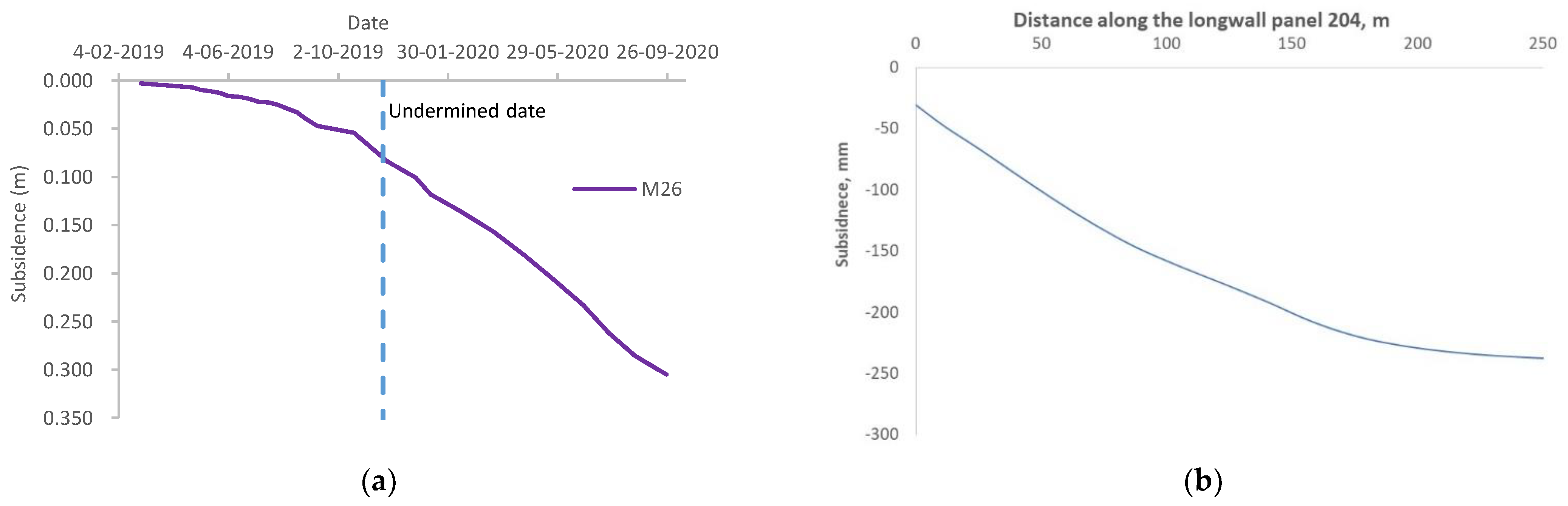
The ground surface subsidence was the only available data from the mine to calibrate the model. The surface subsidence was surveyed above longwall 204, and the subsidence data for five points along the survey line is shown in
Figure 3. These survey points are in and out of the longwall panel. The aim of this calibration is to produce a similar subsidence trend rather than to match the exact data points, as there is only limited data available to compare the magnitudes. The surveyed data show the subsidence of approximately 250–300 mm around and above the mining panels on the ground surface, and there is no significant difference in magnitude between subsidence within and near the longwall goaf. This subsidence profile is different from a typical subsidence profile observed in shallow mining, where substantially large subsidence occurs in the central goaf.
Figure 3 also shows that the model predicted ground subsidence. This value and trend are on par with the mine-provided subsidence profile. This confirms that the numerical model behaves similarly to the mining mechanism observed in the field operation.
5. Influence of Mining and Geological Factors on Overburden Deformation
The mine has the option to adjust extraction sizes, such as the extraction thickness and panel width, to maximize the production while minimizing the risks of water inrush and coal burst. In addition, the strength of the overburden strata may change significantly in different regions due to geological variations. Moreover, the change in pore pressure within the thick aquifer, whose thickness accounts for more than one-third of the thickness of the entire overburden, could result in the strength variation of the aquifer [
31]. These localized uncertainties in the strata may cause the overburden deformation characteristics to behave incoherently.
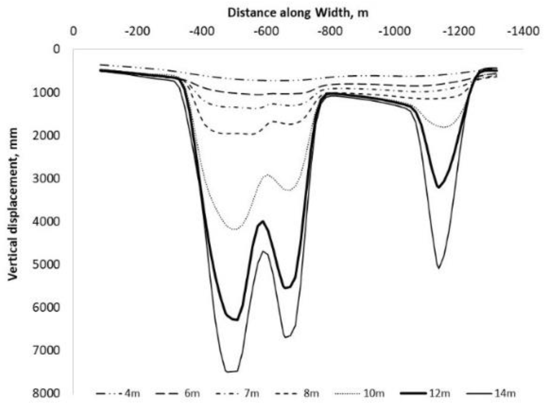
5.1. Influence of Panel Width
When the width-to-depth ratio is low (subcritical mining) and all other parameters remain the same, the increase in the excavation width generally causes an increase in the ground surface subsidence [
27,
28]. Three different excavation widths for longwall 301 are modelled and compared to understand the effect of excavation width on overburden deformation. The excavation widths considered in this study are 147 m (the base case), 200 m, and 268 m. Longwall 301 is mined at the end after longwall 302. Given the model geometry, the increase in width of the longwall 301 panel causes the width of the area pillar to decrease.
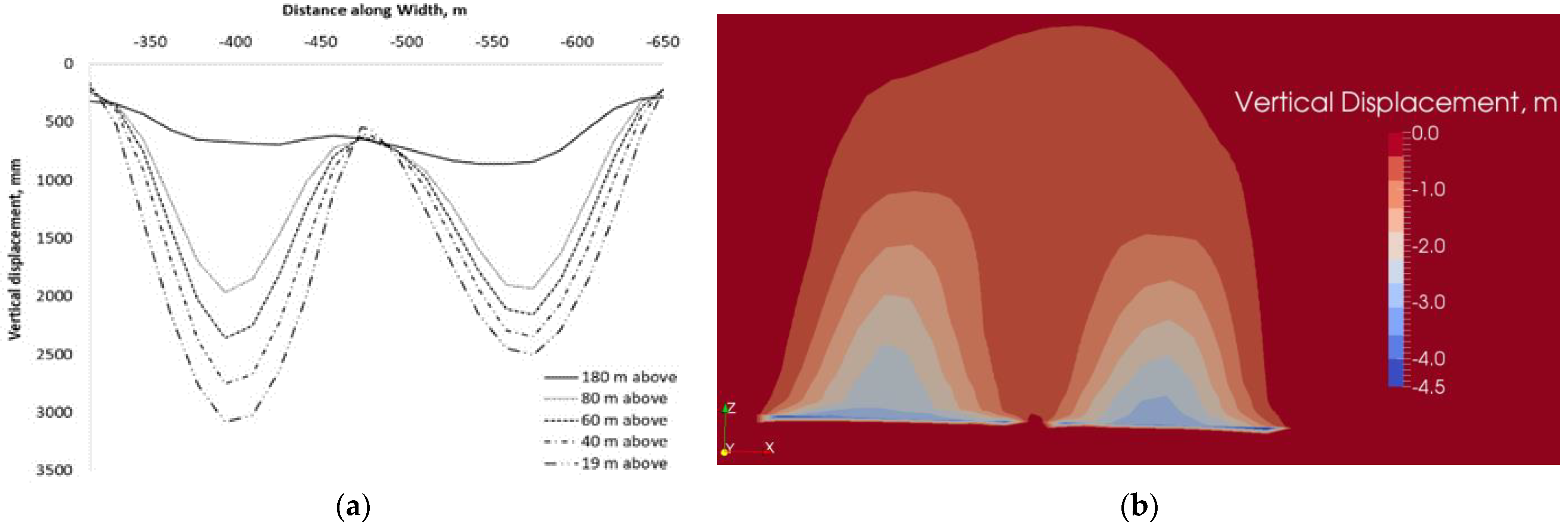
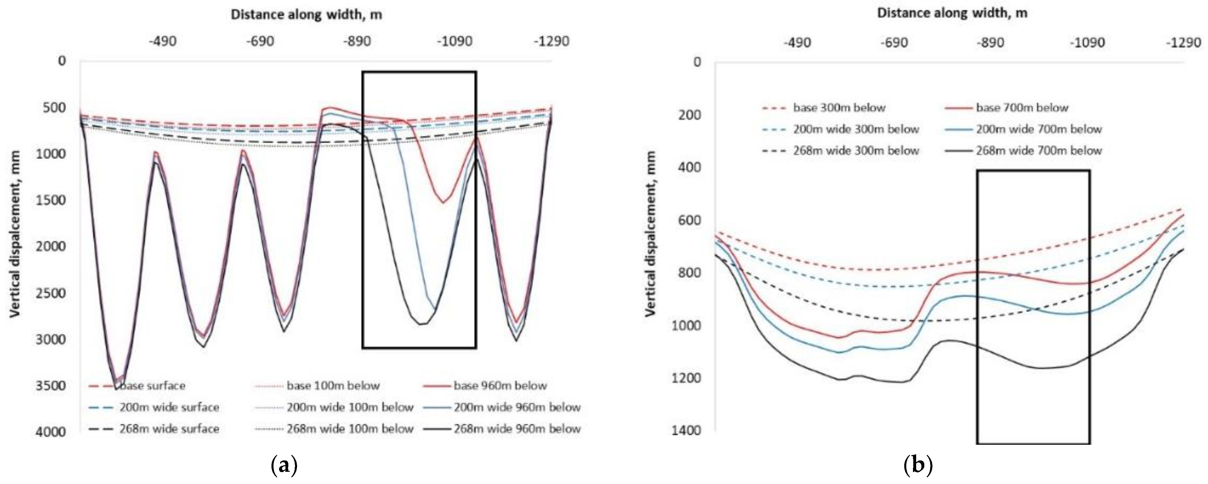
In
Figure 8, the vertical strata movement caused by the excavation of longwall 301 is the second trough from the right-hand side (highlighted by the rectangular box). As the excavation width increases, the vertical displacement of the roof strata 19 m above the mining seam (represented by the 960 depth curves) increases. For the three cases, the maximum vertical displacement at this level is 1.1 m, 2.5 m, and 3 m, respectively (
Figure 8b). As the vertical distance from the strata increases, the difference in the magnitude of vertical displacement lessens among the three cases. For instance, the difference in the vertical displacements at 960 m below the surface (19 m above the longwall) between the base case and the widest panel width is approximately 1.9 m (i.e., 3–1.1 m). The difference reduces to 0.4 m (i.e., 1.2–0.8 m) at 700 m below the ground surface (279 m above the mining seam), and 0.3 m (i.e., 1–0.7 m) at 300 m below the ground surface (679 m above the mining seam).
As the excavation width increases, the area pillar between longwall 205 and longwall 302 decreases in width in the model. This decrease in pillar width, along with the increase of longwall 302 pillar width, causes the increase in vertical displacement of the strata above the pillar zone (
Figure 8a,b). The narrower the pillar width, the larger the subsidence across the mining vicinity. For example, the decrease in pillar width from 220 m to 99 m (due to increasing panel width from 147 m to 268 m) would cause an additional 0.2 m (0.9–0.7 m) subsidence on the ground surface at the lowest point of the subsidence. In this regard, the pillar between Area 2 and Area 3 should have sufficient width to avoid excessive stress concentration in terms of coal burst risk whilst acting as a load-bearing pillar to minimize mining interference with the overburden aquifer. Similarly,
Figure 8a compares ground subsidence in all three cases. The wider panel widths with the narrower area panel cause the higher ground subsidence.
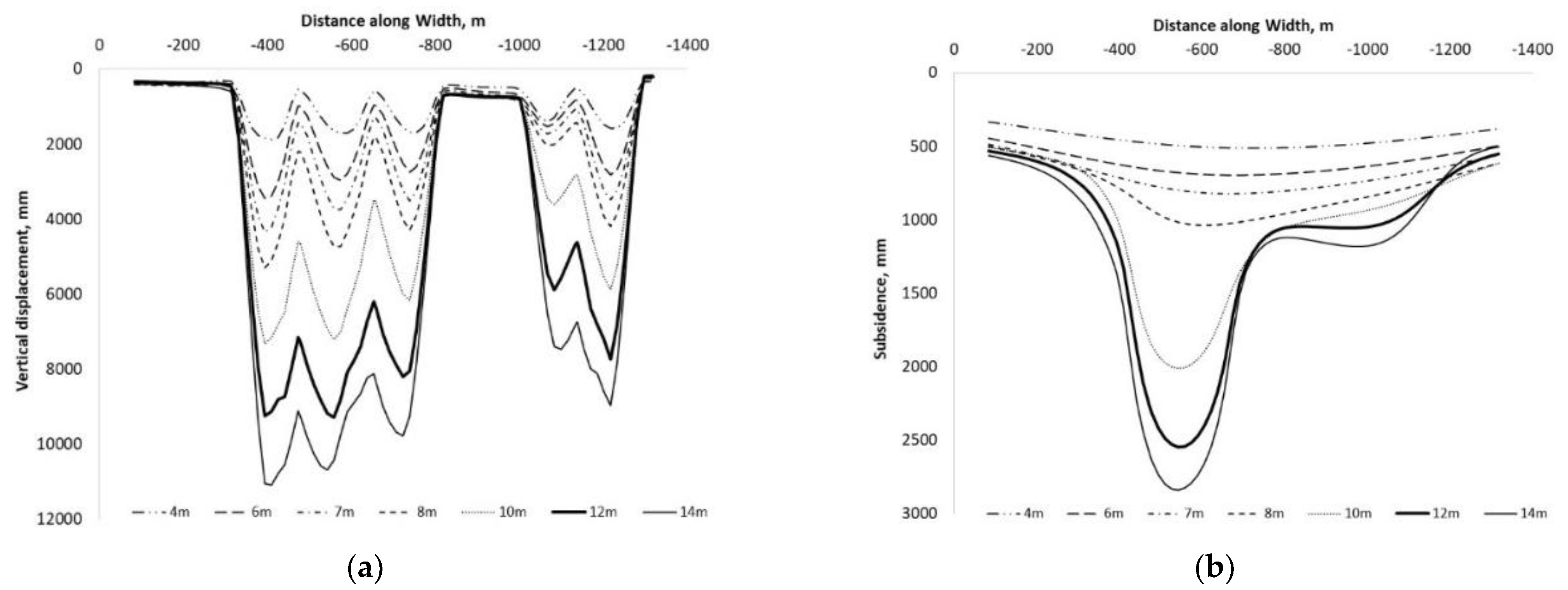
5.2. Influence of Extraction Height
The modelled excavation heights are 4 m, 6 m, 7 m, 8 m, 10 m, and 14 m. In the models, the uniform extraction thickness has been assigned. For instance, for the 14 m extraction height model, all five panels have an extraction height of 14 m. The mine may take different extraction thicknesses for individual panels to adjust overburden deformation behavior, for example, excavating 6 m for Area 2 and 10 m for Area 3. The individual extraction height for each panel height in the same model is not studied in this paper.
Figure 9 shows the vertical displacements and ground subsidence caused by increasing excavation height. As excavation height increases, the vertical displacements of the immediate roof and the ground surface increase. The increase in extraction height from 4 m to 14 m causes the maximum ground subsidence to increase from 0.3 m to 2.8 m. In Area 2, the excavation of a series of three panels (equivalent to a total excavation width of 574 m) causes the total subsidence profile to be a typical subsidence trough as that of a longwall panel in the shallow depth (
Figure 9b) for more than 8 m of excavation thickness. In Area 3, the ground subsidence over the two narrower panels (333 m width in total) is smaller than that of Area 2. This is evident for extraction heights greater than 8 m of excavation thickness.
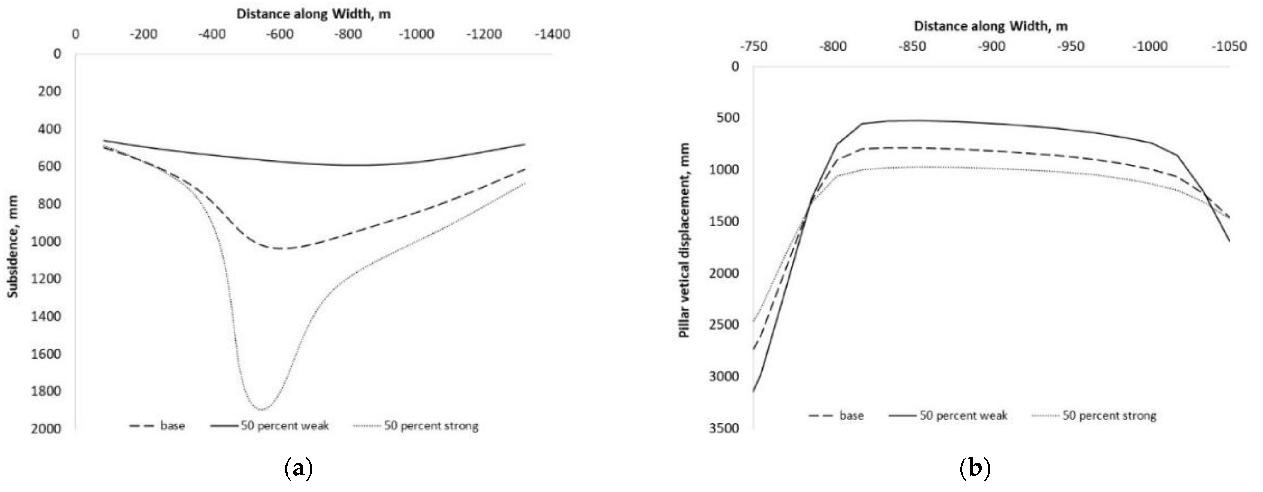
5.3. Influence of Strata Strength
The effect of strata strength on vertical displacement is investigated by changing the strength properties of the strata listed in
Table 2. The cohesion and tensile strength of the strata are halved and doubled from their values in the base model. This is to simulate a potential change of rock strength due to geological variation or change in pore pressure in the thick aquifer caused by water loss. A decrease in pore pressure would result in an increase in strata strength [
31] and thus may influence the deformation characteristics.
Figure 10 shows the results of the three cases with different overburden strengths. In these cases, the extraction height is set as 8 m. The stronger strata result in larger ground subsidence over longwall goaves (
Figure 10a) and the pillars (
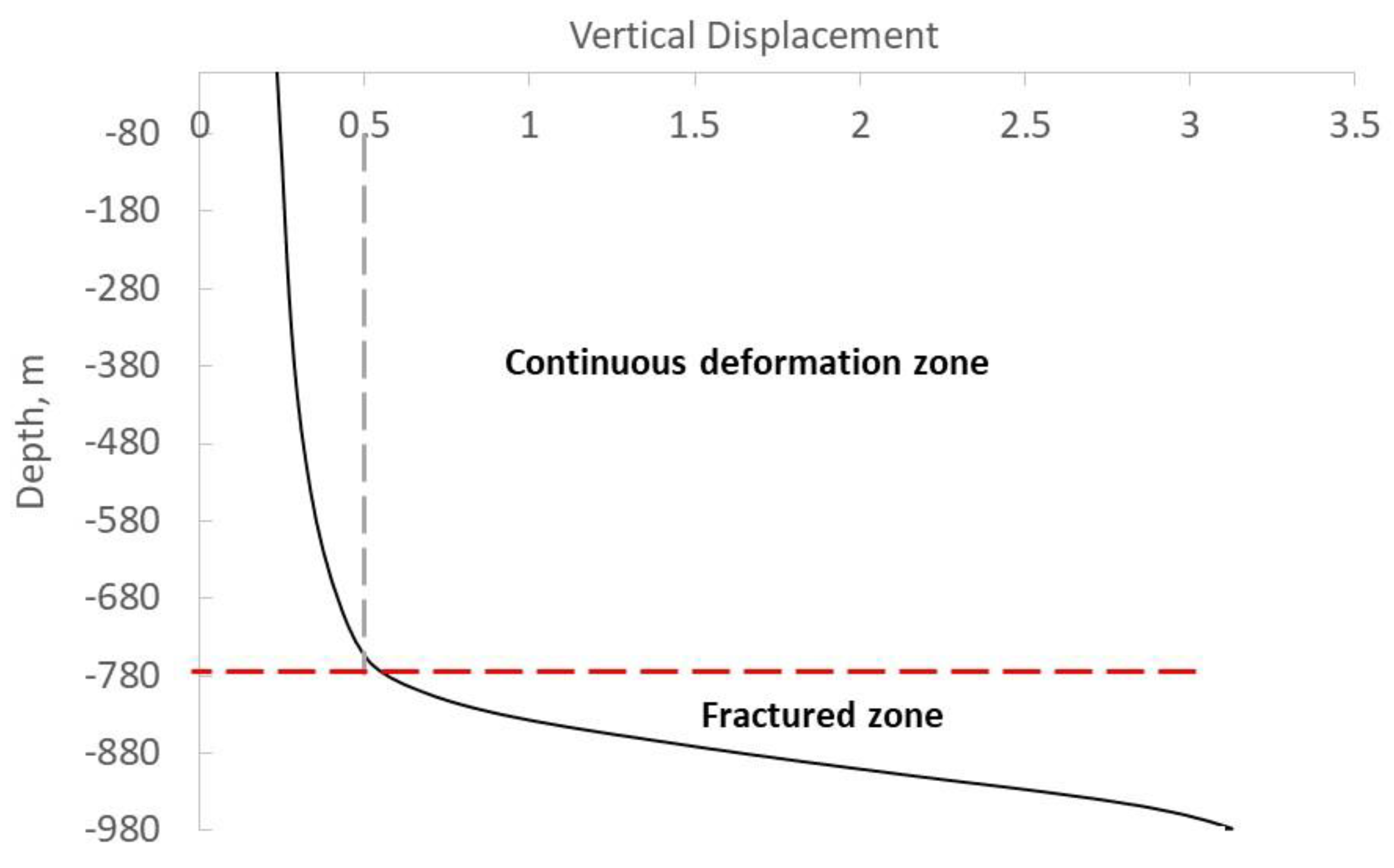
Figure 10b) as well. This result could be related to the extent of the fractured zone. The standard empirical formula to estimate the height of fracture zone used in China [
32,
33] suggests that stronger overburden strata result in a larger vertical extent of the fractured zone. As a result, greater ground subsidence can be induced by the larger fractured zone. The relatively less dilation of strong strata above the fractured zone may also contribute to this phenomenon.
7. Conclusions
The impact of deep longwall operations on strata movement behavior and stress redistribution was investigated with a numerical model. The model was first calibrated with the available subsidence data from the mine, followed by an investigation on the influence of potential changes in mining and geological conditions.
With the extraction thickness less than 8 m, the fractured zone in the overburden is restricted to a certain height, and the overburden further above has minimal deformation resulting in a nearly flat subsidence profile with small magnitude across different panels.
With the extraction thickness greater than 8 m for all the modelled panels, the fractured zone extends to a height that can cause a significant amount of surface subsidence. The cumulative subsidence profile over a series of excavated longwall panels exhibits a trough as that of a single longwall panel. The narrow pillars (7 m wide) between two neighboring longwall panels have little effect on resisting the development of subsidence.
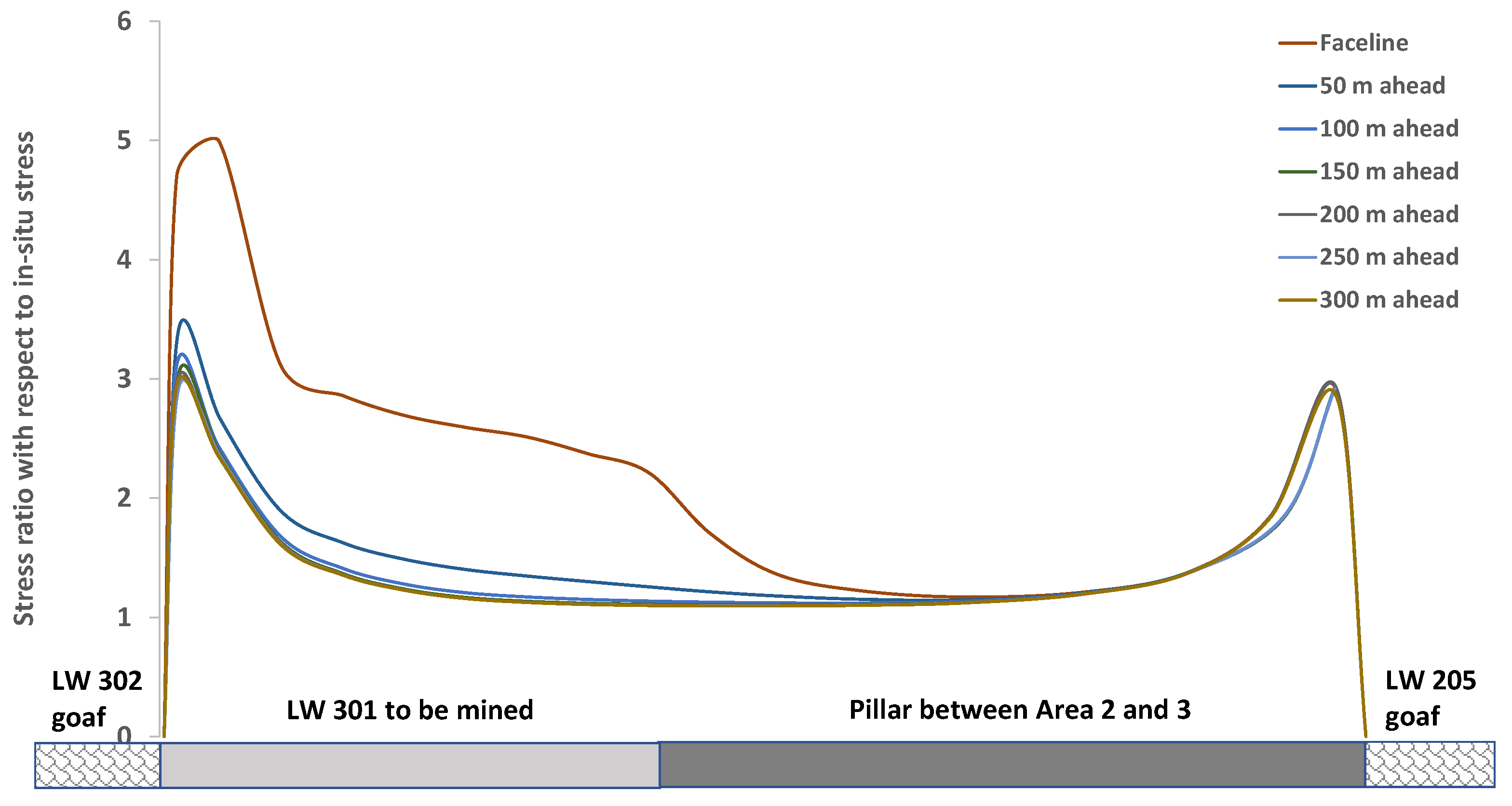
The mine may adjust its extraction parameters, such as panel width and extraction thickness, to balance and minimize the two risks of water inrush from the overlying thick aquifer and coal burst due to stress concentration. Stress concentration over the load-bearing pillar can be up to three to five times the original stress, posing a risk of coal burst. Applying an extraction thickness over 7 m for all panels may breach the thick aquifer located 200 m above the mining seam. Increasing panel width and extraction thickness would result in an increase in the magnitude of the vertical displacement of the overburden strata and, therefore, surface subsidence. Increasing extraction thickness appears to have little effect on the level of stress concentration in the abutment zone. However, the resultant loss of water due to an aquifer breach can increase the stress concentration on coal in abutment zones.


 ,
, 


