Article

Impact of Stimulated Fractures on Tree-Type Borehole Methane Drainage from Low-Permeability Coal Reservoirs

1
Emergency Science Research Academy, China Coal Research Institute, China Coal Technology & Engineering Group Co., Ltd., Beijing 100013, China
2
State Key Laboratory of Coal Mine Disaster Dynamics and Control, Chongqing University, Chongqing 400044, China
3
School of Mines Safety, North China Institute of Science & Technology, Yanjiao 065201, China
4
College of Mining, Guizhou University, Guiyang 550025, China
*
Authors to whom correspondence should be addressed.
Minerals 2022, 12(8), 940; https://doi.org/10.3390/min12080940
Submission received: 28 June 2022 / Revised: 18 July 2022 / Accepted: 23 July 2022 / Published: 26 July 2022
(This article belongs to the Special Issue Fracturing of Coal and Rock Mass)

Abstract

:
Tree-type hydraulic fracturing (TTHF) is a promising method applicable to the effective development of methane in low-permeability coal seams. However, a large-scale application of this technique is limited due to the unclear impact of stimulated fractures by TTHF on the effect of post-fracturing methane drainage. To address this issue, a multi-scale methane flow model of coupled thermo-hydro-mechanical (THM) processes in stimulated coal seams by TTHF was developed and verified against laboratory-based measurements. Using this proposed model, a systematic evaluation of the influence extent of hydraulic fractures connecting sub-boreholes in a tree-type borehole on the drainage effect under different fracture apertures, initial permeabilities of the cleat system, and remnant methane pressures was performed. Detailed simulated results showed that the presence of highly permeable fractures induced by TTHF greatly enhanced, as expected, the drainage efficiency of coal seam methane between the ends of adjacent sub-boreholes, and led to a significant increase in the homogeneity coefficient β. Furthermore, increasing the stimulated fracture aperture and initial cleat permeability or reducing the remnant methane pressure also resulted in a larger value of β, but in turn shortened the lead time of the tree-type borehole. The β’s growth rate for different investigated cases compared to identical simulations without stimulated fractures presented an overall trend of increasing at first and then slowly decreasing with sustained drainage time. Meanwhile, large-aperture hydraulic fractures and lower remnant methane pressure are more beneficial to the drainage effect of tree-type boreholes in the initial stages of drainage. These results portrayed herein can be employed to better understand how fractures generated by TTHF play a role in post-fracturing drainage programs and provide theoretical assistance in engineering applications.

1. Introduction

Coal is one of the world’s main energy supplies for the development of the global economy and society. In recent years, many countries have begun to reduce the use of coal in order to decouple energy-linked CO2 emissions from economic growth [1,2,3,4,5]. However, in 2020, global coal production is still as high as 77.41 billion tons, and coal’s share of the world energy consumption is 27.2% [6]. During the exploitation process of coal resources, coal seam methane (CSM) will be produced. CSM is a form of unconventional gas resource, but is also one of the dangerous greenhouse gases and a major threat to coal mines [7,8]. High-efficiency recovery of CSM prior to and during mining can reduce methane-related accidents in underground coal mines and enable this type of energy to be utilized. In China’s 13th Five-Year Plan for the development and utilization of CSM, a CSM production target of 24 billion m3 by 2020 has been set [9]. In contrast to expectation, the actual production of CSM in 2020 is approximately 10.23 billion m3, which is far below the initial target. The root cause of this result is that the coal’s initial permeability in China is rather low [10,11]. The permeability of over 90% of coal seams is below 0.99 × 10⁻¹⁸ m2 [12]. Low-permeability coal makes CSM drainage difficult. To enhance coal seam permeability, many stimulation techniques via boreholes have been promoted and utilized to increase CSM extraction in Chinese coal mines. Common technologies used in the field include hydraulic flushing, hydraulic slotting, hydraulic fracturing, and pre-splitting blasting.
Relevant scholars have extensively researched borehole stimulation measures. Hydraulic flushing utilizes high-pressure waterjets to erode the coal masses surrounding the borehole in order to form a cavity in the coal seam [13]. Based on a response surface methodology, the coupling effects of the cavity size, initial gas pressure and coal seam permeability on the drainage influenced radius were simulated and investigated by Kong et al. [14]. By conducting a series of simulations, Liu et al. [15] explored the extent to which non-Darcy flow influences methane productivity in a coal seam stimulated by hydraulic flushing. Taking into account the strain-softening behavior of coal, Zhang et al. [16] studied the methane extraction enhancement mechanism of hydraulic flushing and its key influence factors. Fan et al. [17] numerically analyzed the effects of two hydraulic flushing cavities’ size and spacing on methane extraction from a low-permeability coal seam. Unlike hydraulic flushing, hydraulic slotting cuts the coal around the borehole to form an elliptic pressure relief zone around the slot [18,19]. Through a seepage model in FlAC3D software, Shen et al. [20] discussed the stress-permeability coupling impact on methane drainage from slotted coal seams. Gao et al. [21] developed a full-coupled model to study the methane drainage effect of slotted boreholes under thermo-hydro-mechanical (THM) coupling conditions. Considering the damage zone produced by the excavation of slotted boreholes, the law of methane migration in coal seams subjected to hydraulic slotting was elaborated by Zhao et al. [22]. The above findings have promoted the understanding of hydraulic slotting and hydraulic flushing to stimulate low-performance boreholes, but the limited methane drainage effect produced by a small-sized cavity or slot (usually less than 2 m) hinders a large-scale application of these two technologies in underground coalmines.
Hydraulic fracturing and pre-splitting blasting, which are expected to attract considerable drainage efficiency in underground coal mines, expand the drainage area of an ordinary borehole by using high-pressure fluid in the target seams to form artificial fractures. Based on the comprehensive numerical models built by Petrel™ software, Szott et al. [23] reported that the size of the drainage zone regarding the use of blasting is much lower than those in terms of hydraulic fracturing and hydraulic slotting. Fan et al. [24] developed a multiphase simulation model for molding methane drainage from hydraulically fractured coal seams. They focused on the influence of fracturing damage on the efficiency of underground borehole methane drainage. Based on the theory of water-driven gas, Xiao et al. [25] built a CSM flow model during fracturing. It was found that, due to water-driven methane migration and the closure of hydraulically created fractures, a CSM enrichment zone that is conducive to drainage would be formed around the fracturing borehole during hydraulic fracturing. Compared with the length of fractures generated by hydraulic fracturing, the induced fractures under pre-splitting blasting in coal seams are much shorter. Gong et al. [26] firstly quantitatively explored the relationship between the cumulative volume of methane produced from a blasting borehole and the effective stress around it. Considering the interaction between coal seam damage and gas flow, Zhu et al. [27] built a numerical model to understand the details of methane drainage from the coal seam stimulated by pre-splitting blasting. According to the response of stress and longitudinal-wave velocity to blasting, the influence radius of blasting and the corresponding optimal layout of drainage boreholes were investigated by Xie et al. [28]. Although many experienced researchers have pointed out that hydraulic fracturing and pre-splitting blasting technologies can improve the drainage effect of CSM to a certain extent, they still cannot reach the desired levels of methane production from low-permeability coal seams. The main reason for such a result is that the creation of a permeability-enhancing area in the high geo-stress zones will be strongly affected by the principal stress difference and that the induced cracks are easily closed due to physical compaction. Consequently, the Chinese Academy of Engineering recently established a strategic and consultative project on the effective development of CSM in China, which aims to explore suitable ways to considerably stimulate the production of Chinese CSM. How to create a large-scale and uniform fracture network in coal seams is crucial to realize a comprehensive and high-efficiency development of CSM. To address the above issues, a tree-type hydraulic fracturing (TTHF) method for underground methane drainage was proposed [19,29,30]. This method firstly employs a high-pressure water jet drilling system to excavate multi-layer sub-boreholes that extend outward from an ordinary cross-measure borehole to form a tree-type borehole. The cross-measure borehole is drilled by using a mechanical rig, while sub-boreholes with the designed length are carved by a self-propelled bit under high water pressure. A diagram depicting the special system developed for hydraulically drilling tree-type boreholes in underground coal mines is shown in Figure 1. After a tree-type borehole is formed using the high-pressure water jet drilling system, TTHF is carried out, and then the tree-type fracturing borehole is employed for methane drainage.
A field test study in a coal-gas outburst coal mine [30] has showed that the CSM production rate in a tree-type fracturing borehole can be 2.3 times greater than that achieved with a traditional fracturing borehole. Since the TTHF technique has amazing effects on methane production, it is expected to be progressively more favorable. To elaborate on the reasons behind this field-scale phenomenon of increased methane production after TTHF, the impacts of sub-borehole layouts in tree-type boreholes on the fracturing effect were theoretically and experimentally explored by Zuo et al. [31]. They found that, owing to the stress disturbance of adjacent sub-boreholes, hydraulic fractures were guided, and subsequently connected the two sub-boreholes when the layout of sub-boreholes in a tree-type borehole was suitable. The existence of highly conductive fractures will determine the permeability in local portions of the reservoir and affect gas outflow during drainage [32,33,34]. Figure 2 shows a schematic representation of multi-scale methane flow during tree-type borehole drainage after fracturing. However, so far, few considerations have been given to the relationship between hydraulic fractures and methane drainage capacity of tree-type boreholes after TTHF. How the induced fractures influence the methane drainage efficiency of tree-type fracturing boreholes remains still unclear, which limits the further optimization and promotion of the TTHF method for methane extraction in underground coal mines to some extent. Therefore, we aim to address the concern in this paper.
In consideration of these above problems, a multi-scale model correlating methane flow within stimulated fractures, coal cleat, and matrix under THM coupling conditions was introduced to analyze the impacts of stimulated fractures on methane migration during tree-type fracturing borehole drainage. In addition, a quantitative assessment of the extent of the influence of some key factors on tree-type fracturing borehole drainage efficiency was performed. These results could provide insights into CSM drainage performance after TTHF and support the optimization of TTHF in underground coal mines.

2. Computational Model

In this study, a novel model for describing multi-scale methane flow in stimulated coal seams by TTHF under THM coupling conditions is defined based on the following basic assumptions. (a) Coal seam consists of coal matrix, cleats, and hydraulic fractures after the TTHF are conducted. (b) Coal seam is saturated by methane and the methane absorption/adsorption in the coal matrix is subject to the Langmuir isotherm. (c) Methane migration in the coal matrix and cleats is assumed to be laminar flow at small Reynolds numbers obeying Darcy’s law, while methane flow in destressing fractures follows a modified cubic law. (d) The sorption-induced strain of the coal matrix follows a Langmuir-type relationship with its adsorbed methane pressure.

2.1. Governing Equation of Methane Flow in the Stimulated Fractures

Coal seams subjected to TTHF are composed of coal matrix, cleats, and stimulated fractures. The hydraulically induced fractures connect the sub-boreholes to the coal matrix and cleats in the stimulated zones, which serve as primary conduits for methane gushing during tree-type borehole drainage. Methane transport in large-aperture stimulated fractures could generally be described by a modified cubic law [35] and satisfies the mass conservation law [36]. Thus, the following Equation (1) for CSM migration in a stimulated fracture can be represented by:
( w ρ i f ) t T ( w ρ i f f w 2 12 μ T p i f ) = w ( Q f i f + Q m i f )
where w is the stimulated fracture aperture (m); ρ i f is the methane density within the stimulated fracture (kg/m3); t is the methane flow time (s); f is the conductivity factor in terms of stimulated fracture roughness (-); μ is the methane viscosity (Pa·s); T p h f represents the gradient of methane pressure along the stimulated fracture (MPa/m); Q f i f is the mass of methane exchange between the stimulated fracture and its surrounding cleats (kg/(m3•s)); and Q m i f is the mass of methane exchange between the stimulated fracture and its surrounding matrix system (kg/(m3•s)).
Indoor experimental results have suggested that the stimulated fracture aperture is ever-evolving and related to the effective stress acting on it. Since the sorption-triggered swelling/shrinkage and thermal-induced expansion/contraction of the coal matrix could not be neglected during the process of methane drainage, we deduced a new model to encompass their effect on the stimulated fracture aperture. The governing equation describing the ever-evolving aperture of a stimulated fracture could be established as:
w = w 0 exp c f ( p i f 0 p i f ) f a Δ ε s + α T Δ T / 3
where w0 represents the initial fracture aperture (m); cf is the compressibility of the stimulated fracture when the effective stress acting on it changes (1/MPa); and a is the width of the coal matrix, (m). ε s is the methane sorption-triggered strain of the coal matrix, which can be expressed by the representative Langmuir-type equation ε s = ε L p m / p m + p L [-]; ε L and pL denote the Langmuir strain constant (-) and the Langmuir pressure constant (MPa), respectively; pm is methane pressure in the coal matrix system (MPa); αT is the coefficient of thermal-induced expansion (1/K); and T is the temperature of the coal reservoir (K).

2.2. Governing Equation of Methane Flow in Coal Matrix and Cleats

Low-permeability coal seams make it difficult for methane to flow within the coal matrix and cleat system, but the entire process of methane drainage also obeys Darcy’s law and the mass conservation law. The governing equations for controlling methane migration in the coal matrix and cleat system are thereby given as [37,38]:
m m t + k m μ ρ g m p m = Q m f Q m i f m f t + k f μ ρ g f p f = Q m f Q f i f
where km is the matrix permeability (m2); kf is the permeability of the cleat system [m2]; pf is the methane pressure in the cleat system (MPa); and Q m f is the mass of methane exchange between coal matrix and cleats (kg/(m3•s)). mm and mf are the mass of methane within the coal matrix and cleat system (kg/m3), respectively. According to the fact that CSM contains free and adsorbed phases, the total methane sequestered in a coal seam can be calculated from Equation (4):
m m = ϕ m p m ρ g m p n + ρ g m ρ c V L p m p m + P L ( 1 A W ) m f = ϕ f ρ g f
where ϕ m and ϕ f represent the porosity [-] of the coal matrix and cleats, respectively; p n is the standard atmosphere pressure [MPa]; ρ c is the coal density [kg/m3]; VL is the Langmuir volume constant of the coal [m3/kg]; A and W are the content [%] of ash and water within the coal, respectively; ρ g m and ρ g f denote the density of methane within the coal matrix and cleat system, respectively, which are usually given by the ideal gas law:
ρ g m = M g R T p m ρ g f = M g R T p f
where Mg denotes the CH4′s molecular weight (kg/mol); R is the universal gas constant (J/(mol•K)).
Methane exchange among the stimulated fracture, the surrounding matrix, and cleats is actually restrained by a smooth pressure gradient [39]. These exchange masses can be described by Equation (6):
Q m f = ρ g m k m ψ m p m p f μ ; Q m i f = ρ g m k m ψ m p m p i f μ ; Q f i f = ρ g f k f Δ p f p i f μ
where ψ m = 4 ( 1 / a x 2 + 1 / a y 2 ) is the shape factor resulting from the characteristic of the coal matrix [1/m2]; a x and a y denote the spacing (m) of the coal matrix in the x- and y-directions, respectively.
By substituting Equations (4)–(6) into Equation (3), the resulting equation for methane transport within the coal matrix and cleat system after TTHF, Equation (7), is obtained:
m m t + k m μ ρ g m p m = Q m f Q m i f ϕ f ρ f g t + ρ g f ϕ f t + k f μ ρ g f p f = Q m f Q f i f
During methane drainage from the coal seam subjected to TTHF, the velocity of methane flow in unstimulated zones is mainly affected by the permeability of the coal matrix and cleat system. Based on the generalized cubic relationship between the matrix permeability and porosity, and referring to the results of previous research [34,38], the governing equation of the matrix permeability during tree-type fracturing borehole drainage is obtained as:
k m = k m 0 ϕ m ϕ m 0 3 = k m 0 1 1 + S ( 1 + S 0 ) + α ϕ m 0 ( S S 0 ) 3
where km0 is the intrinsic permeability of the coal matrix at the initial CH4 pressure pm0 (m2); ϕ m 0 denotes the intrinsic porosity of the coal matrix (-); S = ε v + p m K s ε s α T T ; S 0 = ε v 0 p m 0 K s ε L p m 0 p m 0 + P L α T T 0 ; α = 1 K / K s is the Biot coefficient for the matrix system (-); and K and Ks are the bulk modulus (MPa) of coal and coal grains, respectively.
The closure degree of cleats differs significantly for different directional strains under geologically relevant stress conditions [40], and thereby the directional permeability evolution of the cleat system, which considers compressive strain, sorption-triggered swelling/shrinkage and thermal expansion/contraction, can be described as [38,41]:
k f i = k f 0 1 + 2 ( 1 R m ) ϕ f 0 ( Δ ε j 1 3 α T Δ T 1 3 Δ ε s ) 3 , i j
where i, j = x, y for the 2D case; Rm = E/ES; E and Es are the elastic modulus (MPa) of coal and coal matrix, respectively; ε j is the strain change in the j-direction affected by the alteration of effective stress (-); kf0 is the intrinsic permeability of the cleat system (m2); and ϕf0 represents the intrinsic porosity of the cleat system (-).

2.3. Governing Equations of Coal Deformation

Assuming that the dual-porosity coal behaves as an elastic medium and its deformation obeys the Hooke’s law, the constitutive equation controlling the deformation of a non-isothermal coal seam containing methane can be given as [34,42]:
G u i , j j + G 1 2 υ u j , i i + f i = α p m , i + β p f , i + K α T T , i + K ε L P L p m + P L 2 p m , i
where f i denotes the body force in the i direction; u i is the displacement component; G = D / 2 1 + υ is the shear modulus [MPa]; D = 1 / E + 1 / a K n 1 ; K = D / 3 1 2 υ ; β = 1 K / a K n is the Biot coefficient for the cleat system (-); and Kn is the normal stiffness of cleats [MPa/m]; υ is the Poisson’s ratio (-).

2.4. Governing Equations of Heat Transfer in Stimulated Coal Seam by TTHF

As the exploitation of deep coal and CSM resources gradually becomes normal, the geothermal gradients in the subsurface can reach 2.84 °C/100 m [43]. The methane extraction from coal seams will induce a temperature drop, which in turn affects the methane flow. In light of the energy conversation law and the influence of drainage-induced temperature variations, the heat transfer in unstimulated zones after TTHF can be expressed by the following Equation (11):
p C M T t + T K g α g ( k m μ p m ) + ( k f μ p f ) + T K α T ε v t = λ m 2 T + ρ g m k m C g μ p m T + ρ g f k f C g μ p f T
where p C M = ϕ m ( ρ g m C g ) + ϕ f ( ρ g f C g ) + ( 1 ϕ m ϕ f ) ( ρ c C s ) denotes the effective heat capacity of the methane-filled coal (J/(m3∙K)); Cg represents the specific heat constant of methane at constant volume (J/(kg∙K)); Cs represents the specific heat constant of coal skeleton (J/(kg∙K)); Kg is the CH4′s bulk modulus (MPa); α g = 1 / T is the thermal expansion coefficient of methane (1/K); ε v = ε 11 + ε 22 + ε 33 is the bulk strain (-); λ M = ϕ m + ϕ f λ g + ( 1 ϕ m ϕ f ) λ s is the thermal conductivity of the methane-filled coal [W/(m∙K)]; λg is the thermal conductivity of methane (W/(m∙K)); and λs is the thermal conductivity of coal skeleton (W/(m∙K)).
Since the conductive heat exchange between matrix and non-isothermal methane in stimulated fractures cannot be neglected during tree-type fracturing borehole drainage, the governing equation for advective-diffusive heat transfer in a stimulated fracture is obtained based on the results of our previous work [34] and presented as:
w ρ i f C g T i f t w T i f K g α g f w 2 12 μ T p i f + λ n T n c = w λ g T 2 T i f + w ρ i f C g f w 2 12 μ T p i f T T i f
where Tif is the temperature in the stimulated fracture (MPa); λ n denotes the heat conductivity constant of the coal matrix in the normal direction, nc, of the fracture (W/(m∙K))(; and λ n T n represents the thermal energy exchange between coal matrix and methane through the stimulated fracture surface (W/m2).

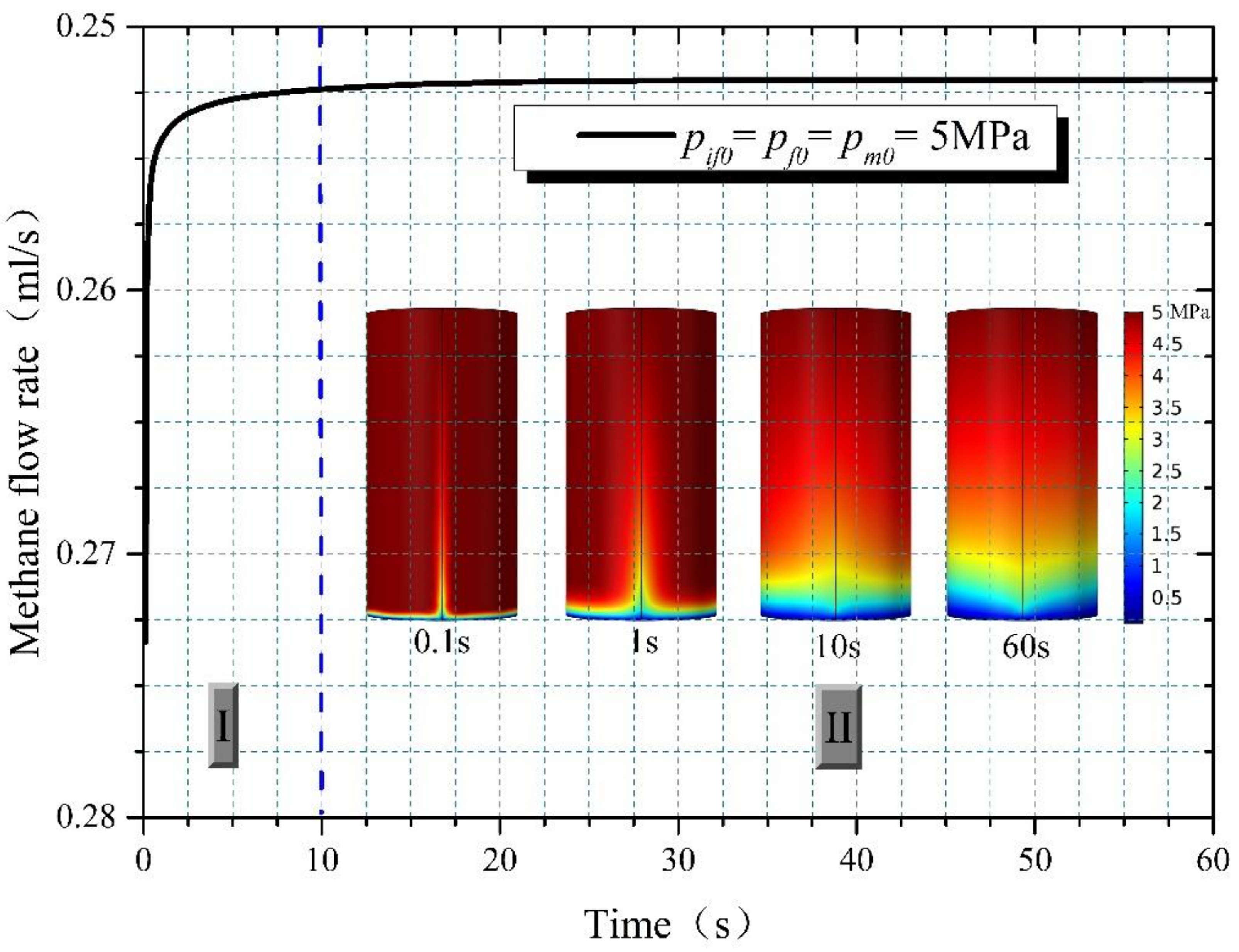
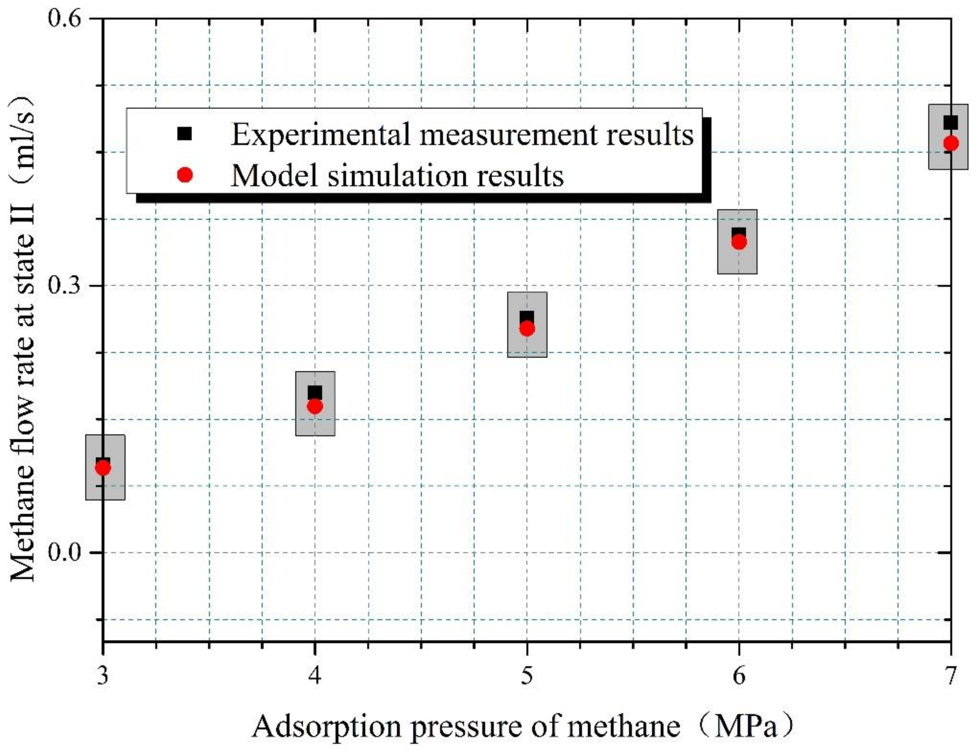
3. Validation of the Multi-Scale THM Model

A typical approach for verifying a mathematical model is the use of indoor experiments [44,45,46]. In order to confirm the reliability of the established multi-scale model for predicting methane flow in coal seams subjected to TTHF, a seepage experiment on a fractured coal core was carried out. The raw coal used for this validation test was taken from the Nanchuan mine in Chongqing, China. It was firstly processed into a cylinder 100 mm in diameter and 200 mm in length (Figure 3a). A through-going fracture was then created in the middle of the sample using the wire cutting method. Notice that because the high fragmentation degree and poor integrity of splitting coal samples based on the Brazilian splitting technique will impact on the results of seepage experiments [47,48], the wire cutting method was thus adopted in this paper. After the specimen was prepared, this indoor experiment was performed by using a tri-axial fracturing and seepage testing system, which can simulate the process of gas flow within intact and fractured rock masses under different THM coupling conditions [49]. During the experiment, an axial stress of 15 MPa and a confining pressure of 12 MPa was applied to the specimen, and a temperature of 40 °C was maintained in the confining pressure cell. Finally, the lab results were used to test the THM model’s ability to characterize methane flow behavior in fractured coal seams.
As shown in Figure 3, the cylindrical model’s boundary conditions were set to match the laboratory data. An inject pressure pin was applied to the upper side of the model, and the adsorption pressure of methane in the core was equal to the inject pressure pin before the experiment started. An outlet pressure pout was applied to the bottom side of the model. A constant confining pressure pcon were applied to the other sides. The coal parameters used in this validation test were collected from experimental results and the published literature [50], as given in Table 1.
During the experiment, it can be found that the methane flow rate at the outlet of the sample varies with time, as displayed in Figure 4. For the sake of analysis, the evolution curve of the methane flow rate could be considered in two brief phases: the rapid outflow phase I and the stable outflow phase Ⅱ. Table 2 presents a comparative analysis of the measured methane flow values obtained through laboratory measurement and model simulation when the adsorption pressure of methane within the core is 5 MPa. There are slight errors in the simulation compared to the experimental values. Meanwhile, the comparison of stable flow rates in the state Ⅱ under different adsorption pressure is performed. Results in Figure 5 suggest that the simulated results well match with the measured data in the laboratory experiment. This implies that our multi-scale model can achieve a precise description of methane flow in fractured coal reservoirs under the THM coupling conditions considered.

4. Numerical Simulation of Methane Drainage from a Coal Seam Subjected to TTHF and Discussion

4.1. Model Generation and Description

In this section, a model problem in terms of CSM drainage after TTHF is studied to determine the effect of hydraulic fractures induced by TTHF under different fracture apertures, initial permeabilities of the cleat system, and remnant CSM pressures. The model seam’s parameters used in the simulations are from several published articles [11,33,38,41,51], as listed in Table 3. In order to establish a simulation model corresponding to the actual situation under geologic conditions, referring to our previous research results [31], a relationship between the sub-borehole length, the initial angle of tree-type borehole, the ground stress difference, and the oriented angle is used in this paper. The suitable oriented angle between each sub-borehole in a tree-type fracturing borehole to ensure the effective guidance of the hydraulic fractures can be thus calculated and designed according to the geological condition of the model coal seam. Figure 6 shows the geometric layout of sub-boreholes in the tree-type fracturing borehole and the associated model domain considered for stimulated methane drainage after TTHF. The models were built using an adaptive mesh mode with the aid of Comsol Multiphysics software (COMSOL Inc., Burlington, MA, USA). It had dimensions of 50 m (x) × 50 m (y) and contained a tree-type borehole and eight fractures formed by TTHF. The main tree-type borehole’s diameter was 153 mm and the diameter of each sub-borehole was 25 mm, as presented in Figure 6a. For the model’s mechanics’ boundary conditions, loading stresses of 12.5 MPa and 19.5 MPa were applied to the upper and right sides, respectively, and the left and bottom sides were set as roller boundaries with fixed normal displacement. The maximum horizontal stress was assumed to be in the x-direction. For methane flow calculation, a zero-flow boundary was applied to all sides of the simulation domain, while a pressure of 15.5 kPa was applied to the tree-type borehole wall based on the field data of continuous suction drainage. In sight of the fact that the CSM will be produced from the fracturing borehole during the flowback process of the water-base fracturing fluid, the remnant methane pressure and temperature in the model domain were estimated as 1 MPa and 323 K, respectively. The governing equations of the multi-scale THM model were input into Comsol and subsequent calculations were performed. For comparative analysis, a scenario without stimulated fractures before TTHF was also calculated under the determined conditions. During the simulations performed herein, a homogeneity coefficient β is used to evaluate the drainage effect of tree-type boreholes, which is given by the following Equation (13):
β = S e π L max 2
where β represents the homogeneity degree of tree-type borehole methane drainage from a coal seam (-); Se is the effective drainage area where the CSM pressure is reduced to below 0.74 MPa due to sustained drainage [52] (m2); and Lmax is the length of the longest sub-borehole in a tree-type borehole (m).

4.2. Simulation and Discussion

Figure 7 depicts the nephogram of methane pressure in the matrix after 10 days, 100 days, and 500 days of drainage from the model coal seam without or with stimulated fractures. With the increase of drainage duration, the rapid decrease of methane pressure can be observed in the vicinity of sub-boreholes and the drainage zone is gradually enlarged. Particularly for the case under the drainage scenario after TTHF, the methane between the ends of adjacent sub-boreholes is drained more effectively owing to the presence of these stimulated fractures. The drainage zone of the tree-type fracturing borehole is co-determined by the sub-boreholes and the stimulated fractures, which is the obvious difference between TTHF and other borehole stimulation methods [23]. It seems that the highly permeable fractures induced by TTHF can effectively promote methane desorption from the matrix and subsequent flow to sub-boreholes. Actually, in most engineering applications, it is usually easy to leave some invalid drainage areas between the ends of adjacent sub-boreholes while the methane is only drained by a tree-type borehole with long sub-boreholes [38,53]. Generating some hydraulic fractures to connect these adjacent sub-boreholes in a tree-type borehole can be just enough to address the issue to some extent.
To quantify the impact of the stimulated fractures on the methane drainage effect, the time evolutions of the tree-type borehole’s homogeneity coefficient under both drainage scenarios are further calculated and given in Figure 8. The figure shows that β undergoes a slowly increasing trend as the drainage time prolongs and that, after being drained for a similar amount of time, there is a significant difference in β for the two cases. When these hydraulically induced fractures exist between each sub-borehole in the tree-type borehole, an increase in β is observed compared to the case without stimulated fractures. The growth rate is clearly fluctuant for drainage times from 0 to 500 days; it increases sharply, reaching the maximum value of 48.6% after 123 days, and then slowly decreases with the drainage time, and finally remains around 26.5% after 500 days. The reason that the growth rate remarkably varies with drainage time could be because β is clearly affected by both the sub-boreholes and the stimulated fractures in the initial period of drainage, but after numerous days of drainage, there is a weaker effect of highly preamble fractures on β arising from the substantial drop in methane pressure around the tree-type boreholes. According to Equation (13), the equation for calculating the homogeneity coefficients of a tree-type borehole during drainage, it can be readily understood that the methane in the coal around the tree-type borehole is drained homogeneously and effectively when β reaches one at a given drainage time. The drainage time when β is identical to one is the so-called lead time for effectively reducing the methane pressure near the tree-type borehole. Thus, it can be obtained from Figure 8 that the lead time of the tree-type borehole after considering the hydraulic fractures induced by TTHF is 157 days, whereas the lead time for the simulation without stimulated fractures is 475 days. The existence of stimulated fractures between sub-boreholes reduces the lead time of the tree-type boreholes by approximately 66.9%. The above analyses imply that the tree-type borehole drainage efficiency is sensitive to the presence of fractures induced by TTHF, but the influence of stimulated fractures firstly increases to the maximum and then gradually decreases with time. This result might be closely related to the closure degree of stimulated fractures during drainage [25,54].

4.2.1. Effect of Stimulated Fracture Aperture

Figure 9 gives the details of the relationship between β and the aperture of stimulated fractures in the domain, and the growth rate of β for different stimulated fracture apertures compared to the no-fracture case is also presented. From this figure, striking differences in the homogeneity coefficient β could be observed as the aperture of these stimulated fractures changes. For any given time of extraction, the larger the stimulated fracture aperture, the larger the homogeneity coefficient β. More importantly, when the aperture of these fractures induced by TTHB is increased from 1 mm to 3 mm, the lead time of the tree-type borehole is decreased from 288 days to 130 days, a significant reduction of about 55%. Moreover, it also can be found that the larger these stimulated fractures’ aperture, the earlier the maximum value of the β’s growth rate occurs. This means that the existence of large-aperture hydraulic fractures connecting sub-boreholes in a tree-type borehole has a considerable impact on CSM drainage effect, especially in the early extraction stages. The reason for this phenomenon could be that more adsorbed methane in the coal seam is ejected in the initial extraction stages thanks to the bigger aperture of these fractures formed by TTHF, but the effective stress reduction caused by sustained suction extraction will make the aperture of these stimulated fractures become smaller, weakening the influence of stimulated fractures on CSM drainage effect. Therefore, adopting a series of applicable methods to further strengthen tree-type borehole methane drainage in low-permeability coal seams at the early post-fracturing period may be more effective, rather than blindly increasing the drainage time.

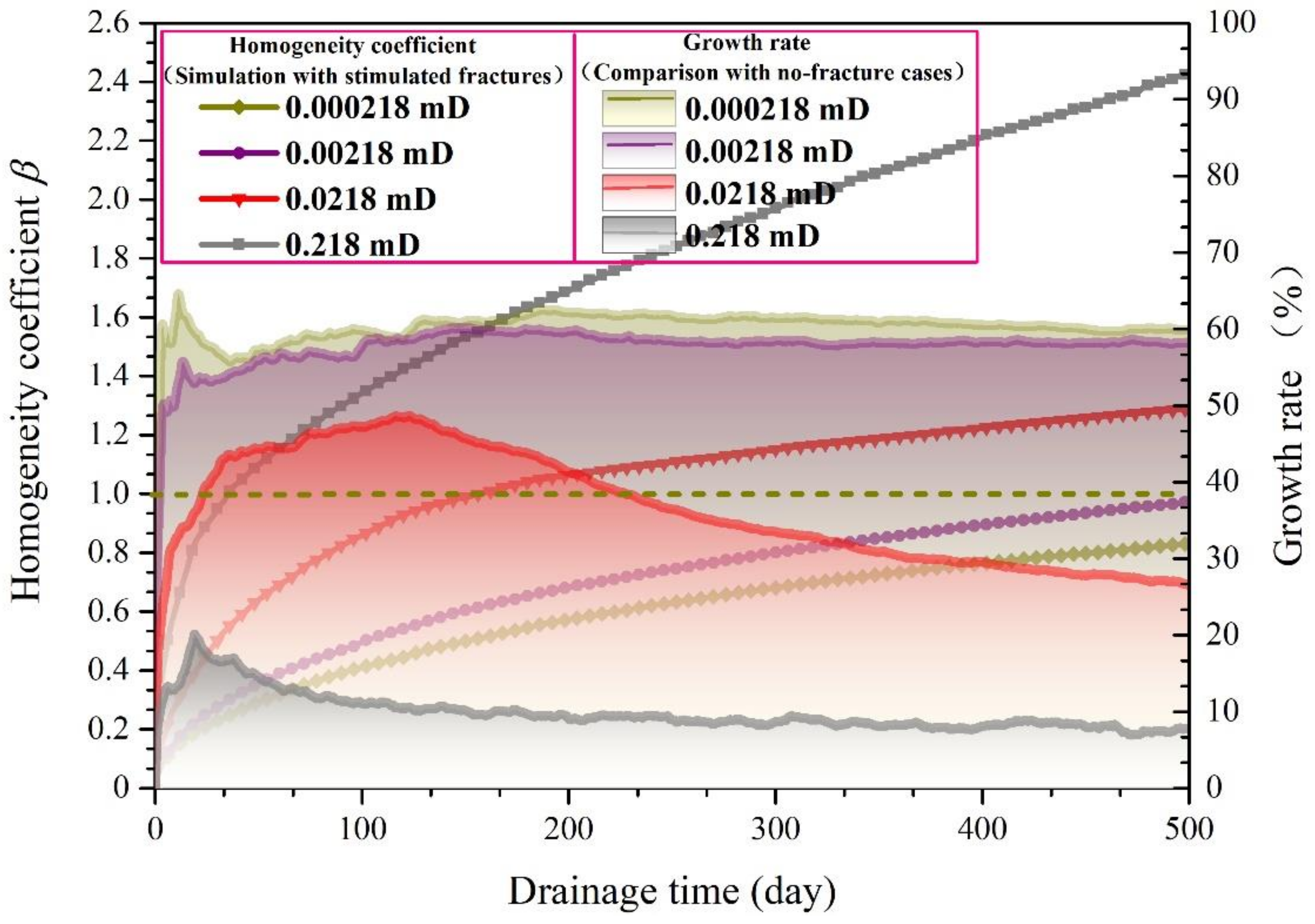
4.2.2. Effect of Initial Permeability of the Cleat System

Figure 10 displays the evolution of the homogeneity coefficient β with different coal cleat permeabilities after TTHF and each respective growth rate of β compared to an identical simulation with no stimulated fractures. It could be observed from Figure 10 that, within the similar drainage time, the homogeneity coefficient β of the tree-type borehole increases with the improvement of the initial permeability of the cleat system. In the range of the cleat permeability considered, alternating the cleat permeability triggers the higher change in β after a relatively long-term drainage. When the initial permeability of the cleat system in the model domain is shifted from 0.000218 mD to 0.00218 mD and from 0.0218 mD to 0.218 mD, the β increases from 0.83 to 0.97 and from 1.29 to 2.43 after 500 days of extraction, respectively. Results in this figure also indicate that the lead time of the tree-type borehole increases greatly as the cleat permeability decreases. Particularly for the two cases when kf0 = 0.000218 mD and kf0 = 0.00218, the value of β at 500 days is still less than one. At this moment, although several stimulated fractures exist between sub-boreholes, the methane around the tree-type boreholes is not drained effectively. Intriguingly, we also can discover that at the same drainage time, the smaller the cleat permeability, the larger the growth rate of β. Because these fractures induced by TTHF are present, the average growth rate for a cleat permeability of 0.000218 mD is as high as 60.4% during the 500-day extraction process while the average growth rate for permeability of 2.18 mD is only 9.9%. These relations shown in Figure 10 suggest that the impact of fractures generated by TTHF on methane drainage becomes fairly pronounced when the intrinsic permeability of the coal seam is quite low, but a small number of stimulated fractures may not fully fix the underlying problem of methane flow difficulty in the coal if these sub-boreholes of a tree-type borehole is too long [11]. Thus, to realize a better drainage effect in the low-permeability coal around a tree-type borehole, it is highly recommended to arrange a quantity of short sub-boreholes in the tree-type borehole based on the TTHF design principle for fracturing and drainage, even though it will reduce the effective drainage scope to some extent.

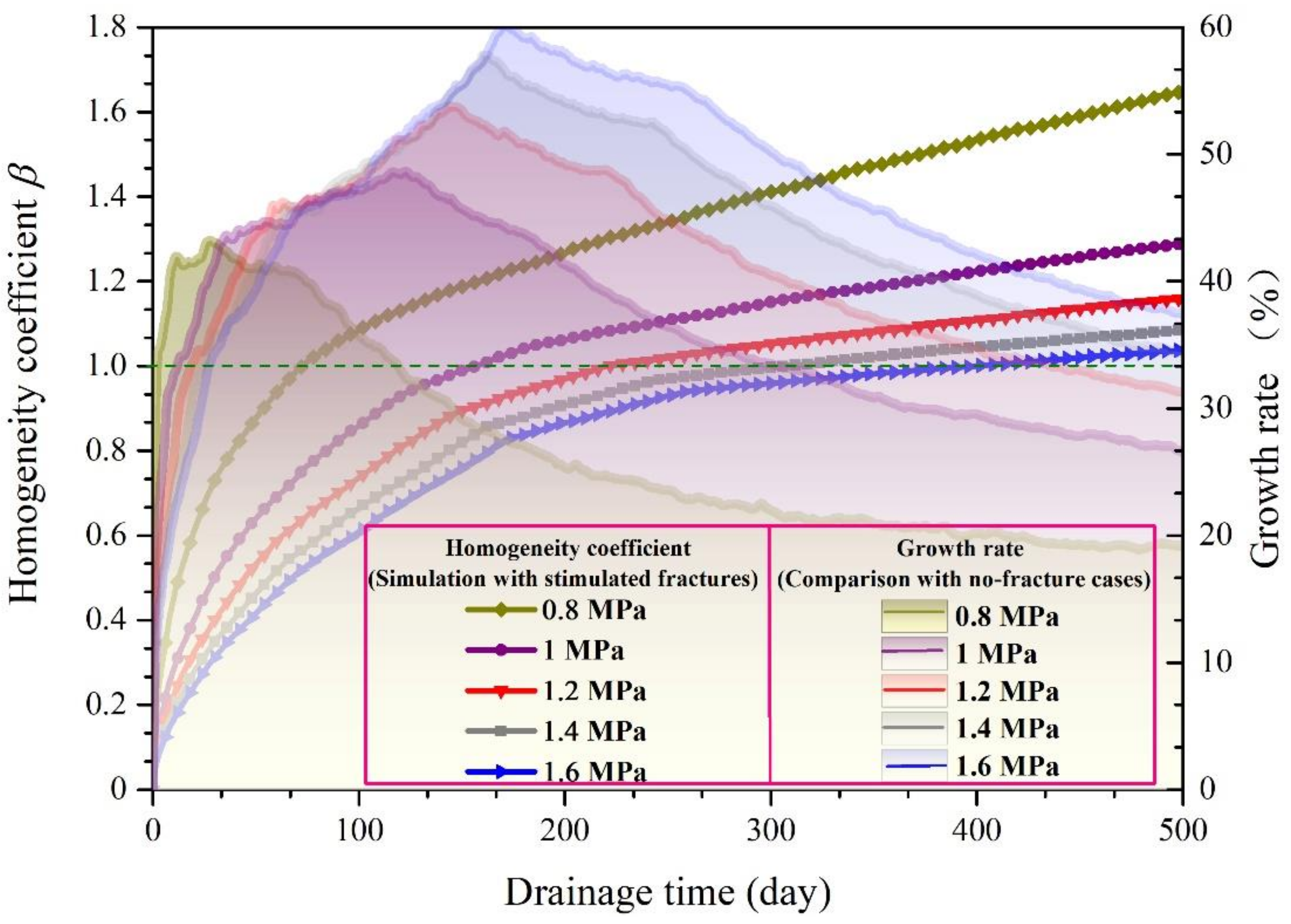
4.2.3. Effect of Remnant CSM Pressure

Owing to the extraction of the fracturing fluid and methane after TTHF, the remnant methane pressure in the coal seam will influence the drainage performance of the tree-type fracturing borehole with the passage of drainage time. Figure 11 shows the impacts of different remnant CSM pressures on the tree-type borehole’s β after TTHF. As can be seen from Figure 11, β decreases while the remnant methane pressure is increased at any given drainage time, which in turn increases the lead time for the tree-type borehole. After 500 days of extraction, β is reduced by approximately 29.7% and 10.5% when the remnant methane pressure in the model domain is varied from 0.8 MPa to 1.2 MPa and from 1.2 MPa to 1.6 MPa, respectively. The degree of change in the tree-type borehole’s β becomes more evident in the lower ranges of the remnant CSM pressure discussed. By comparison with simulations with no stimulated fractures, the growth rate of β for different remnant methane pressures is also given in Figure 10. The relationship between the growth rate of β and remnant methane pressure appears reverse when the drainage time reaches a certain value. If the amount of extraction time is similar, the growth rate of β slightly decreases in the initial stages of the entire extraction process, and significantly increases in the later stages of the entire extraction process as the remnant methane pressure is increased. This reversal phenomenon implies that the larger the CSM pressure during drainage after TTHF, the smaller impact of stimulated fractures on the drainage effect in the initial drainage stages, but the greater the impact in the later drainage stages. The reason for these results might be because, when the CSM pressure increases, more methane is required to be extracted and a relatively small effective drainage area for a similar drainage time occurs [21,55], resulting in a weakening effect of stimulated fractures at the beginning of the extraction process. However, along with a period of continuous suction drainage, the effective drainage zone expands and the influence of high-pressure gradient in the coal seam with a higher methane pressure makes the effect of stimulated fractures on the drainage effect become significant.

5. Conclusions

High-efficiency extraction of coal mine methane (CMM) is critical for mitigating the risk of methane-related disasters during mining. Tree-type hydraulic fracturing (TTHF) is recognized as an advance and effective measure to achieve a desired drainage effect in low-permeability coal seams. Herein, we firstly established a multi-scale thermo-hydro-mechanical (THM) coupling model for simulating methane flow in coal seams subjected to TTHF. Then it was used to analyze the impact of hydraulically induced fractures between sub-boreholes on tree-type borehole methane drainage effect with different fracture apertures, initial permeabilities of the cleat system, and remnant CSM pressures. The primary conclusions are then drawn.
The mathematical equations of coal deformation, heat transfer, and methane flow within stimulated fractures, coal cleat, and matrix under THM coupling conditions were derived and verified. The multi-scale THM model results were in good accord with the experimental measurements, which confirmed the accuracy of this proposed model.
A homogeneity coefficient β was introduced to quantitatively assess the tree-type boreholes’ drainage effect. When considering interconnected fractures between tree-type sub-boreholes, the methane between the ends of adjacent sub-boreholes can be extracted effectively, and that β increases considerably. The growth rate of β rises to a maximum sharply at first and then slowly decreases over time. This contributes to the conclusion that the tree-type borehole drainage efficiency is sensitive to the presence of fractures generated by TTHF and the sensitivity varies greatly with drainage time.
After TTHF, β increases gradually with the increase of the stimulated fracture aperture and initial cleat permeability but the corresponding lead time of the tree-type borehole would be shortened. Large-aperture hydraulic fractures that connect sub-boreholes in a tree-type borehole have a considerable impact on CSM drainage effect during the preliminary stages of drainage. This influence will extend to the entire extraction process as the coal seam permeability becomes lower. When the remnant methane pressure in a TTHF stimulated coal seam is increased, β will decrease at any given drainage time, while stimulated fractures have a relatively small impact on the drainage effect during the preliminary drainage stages but have a greater impact in the later drainage stages.

Author Contributions

Conceptualization, L.Z. and S.Z.; writing—original draft preparation, L.Z.; writing—review and editing, Q.Q. and X.C.; Supervision, R.B.; Validation test and Data curation, L.Z. and K.D. investigation and analysis, J.C. All authors have read and agreed to the published version of the manuscript.

Funding

This work was financially supported by the China Postdoctoral Science Foundation (No. 2021M691390), the Key R&D Plan Program of Hebei Province of China (No. 22375401D), the Fundamental Research Funds for the Central Universities (No. 314202000), and the Langfang science and technology research and development program (No. 2020013162).

Institutional Review Board Statement

Not applicable.

Informed Consent Statement

Not applicable.

Data Availability Statement

The data used to support the findings of this study are presented in the article. Further inquiries can be directed to the corresponding author.

Conflicts of Interest

The authors declare that they have no conflict of interest.

References

  1. Sheng, J.; Tunnicliffe, R.; Ganesan, A.L.; Maasakkers, J.D.; Shen, L.; Prinn, R.G.; Song, S.; Zhang, Y.; Scarpelli, T.; Anthony Bloom, A.; et al. Sustained methane emissions from China after 2012 despite declining coal production and rice-cultivated area. Environ. Res. Lett. 2021, 16, 104018. [Google Scholar] [CrossRef]
  2. Adedoyin, F.F.; Gumede, M.I.; Bekun, F.V.; Etokakpan, M.U.; Balsalobre-Lorente, D. Modelling coal rent, economic growth and CO2 emissions: Does regulatory quality matter in BRICS economies? Sci. Total Environ. 2020, 710, 136284. [Google Scholar] [CrossRef] [PubMed]
  3. Lin, J.; Fridley, D.; Lu, H.; Price, L.; Zhou, N. Has coal use peaked in China: Near-term trends in China’s coal consumption. Energy Policy 2018, 123, 208–214. [Google Scholar] [CrossRef]
  4. Garcia, E.; Liu, H. Ilmenite as alternative bed material for the combustion of coal and biomass blends in a fluidised bed combustor to improve combustion performance and reduce agglomeration tendency. Energy 2022, 239, 121913. [Google Scholar] [CrossRef]
  5. Nandimandalam, H.; Gude, V.G.; Marufuzzaman, M. Environmental impact assessment of biomass supported electricity generation for sustainable rural energy systems—A case study of Grenada County, Mississippi, USA. Sci. Total Environ. 2021, 802, 149716. [Google Scholar] [CrossRef] [PubMed]
  6. BP. Statistical Review of World Energy. Available online: https://www.bp.com/content/dam/bp/business-sites/en/global/corporate/pdfs/energy-economics/statistical-review/bp-stats-review-2021-full-report.pdf?utm_source=BP_Global_GroupCommunications_UK_external&utm_medium=email&utm_campaign=11599394_Statistical%20Review%202020%20-%20on%20the%20day%20reminder&dm_i=1PGC%2C6WM5E%2COV0LQ4%2CRQW75%2C1 (accessed on 26 October 2021).
  7. Neininger, B.G.; Kelly, B.F.J.; Hacker, J.M.; Lu, X.; Schwietzke, S. Coal seam gas industry methane emissions in the Surat Basin, Australia: Comparing airborne measurements with inventories. Philos Trans. A Math. Phys. Eng. Sci. 2021, 379, 20200458. [Google Scholar] [CrossRef]
  8. Hendel, J.; Lukanko, L.; Macuda, J.; Kosakowski, P.; Loboziak, K. Surface geochemical survey in the vicinity of decommissioned coal mine shafts. Sci. Total Environ. 2021, 779, 146385. [Google Scholar] [CrossRef]
  9. Jia, L.; Peng, S.; Xu, J.; Yan, F. Interlayer interference during coalbed methane coproduction in multilayer superimposed gas-bearing system by 3D monitoring of reservoir pressure: An experimental study. Fuel 2021, 304, 121472. [Google Scholar] [CrossRef]
  10. Ge, Z.; Cao, S.; Lu, Y.; Gao, F. Fracture mechanism and damage characteristics of coal subjected to a water jet under different triaxial stress conditions. J. Pet. Sci. Eng. 2022, 208, 109157. [Google Scholar] [CrossRef]
  11. Zhang, L.; Ge, Z.; Lu, Y.; Zhou, Z.; Xiao, S.; Zuo, S. Permeability Enhancement and Methane Drainage Capacity of Tree-type Boreholes to Stimulate Low-permeability Coal Seams. Arab. J. Sci. Eng. 2020, 46, 573–586. [Google Scholar] [CrossRef]
  12. Ge, Z.; Lu, Y.; Zhou, D.; Zuo, W.; Xia, B. Study on regular and mechanism of coal bed methane desorption experiment under sonic vibrating of cavitation water jets. Meitan Xuebao/J. China Coal Soc. 2011, 36, 1150–1155. [Google Scholar]
  13. Bo, L.; Liu, M.; Liu, Y.; Wang, N.; Guo, X. Research on pressure relief scope of hydraulic flushing bore hole. Procedia Eng. 2011, 26, 382–387. [Google Scholar] [CrossRef] [Green Version]
  14. Kong, X.; Wang, E.; Liu, X.; Li, N.; Chen, L.; Feng, J.; Kong, B.; Li, D.; Liu, Q. Coupled analysis about multi-factors to the effective influence radius of hydraulic flushing: Application of response surface methodology. J. Nat. Gas Sci. Eng. 2016, 32, 538–548. [Google Scholar] [CrossRef]
  15. Liu, Q.; Cheng, Y.; Dong, J.; Liu, Z.; Zhang, K.; Wang, L. Non-Darcy Flow in Hydraulic Flushing Hole Enlargement-Enhanced Gas Drainage: Does It Really Matter? Geofluids 2018, 2018, 1–15. [Google Scholar] [CrossRef]
  16. Zhang, H.; Cheng, Y.; Yuan, L.; Wang, L.; Pan, Z. Hydraulic flushing in soft coal sublayer: Gas extraction enhancement mechanism and field application. Energy Sci. Eng. 2019, 7, 1970–1993. [Google Scholar] [CrossRef] [Green Version]
  17. Fan, Y.; Shu, L.; Huo, Z.; Hao, J.; Li, Y. Numerical simulation of sectional hydraulic reaming for methane extraction from coal seams. J. Nat. Gas Sci. Eng. 2021, 95, 104180. [Google Scholar] [CrossRef]
  18. Lu, Y.; Liu, Y.; Li, X.; Kang, Y. A new method of drilling long boreholes in low permeability coal by improving its permeability. Int. J. Coal Geol. 2010, 84, 94–102. [Google Scholar] [CrossRef]
  19. Lu, Y.; Ge, Z.; Yang, F.; Xia, B.; Tang, J. Progress on the hydraulic measures for grid slotting and fracking to enhance coal seam permeability. Int. J. Min. Sci. Technol. 2017, 27, 867–871. [Google Scholar] [CrossRef]
  20. Shen, C.; Lin, B.; Sun, C.; Zhang, Q.; Li, Q. Analysis of the stress–permeability coupling property in water jet slotting coal and its impact on methane drainage. J. Pet. Sci. Eng. 2015, 126, 231–241. [Google Scholar] [CrossRef]
  21. Gao, F.; Xue, Y.; Gao, Y.A.; Zhang, Z.Z.; Teng, T.; Liang, X. Fully coupled thermo-hydro-mechanical model for extraction of coal seam gas with slotted boreholes. J. Nat. Gas Sci. Eng. 2016, 31, 226–235. [Google Scholar] [CrossRef]
  22. Zhao, Y.; Lin, B.; Liu, T.; Kong, J.; Zheng, Y. Gas flow in hydraulic slotting-disturbed coal seam considering stress relief induced damage. J. Nat. Gas Sci. Eng. 2020, 75, 103160. [Google Scholar] [CrossRef]
  23. Szott, W.; Słota-Valim, M.; Gołąbek, A.; Sowiżdżał, K.; Łętkowski, P. Numerical studies of improved methane drainage technologies by stimulating coal seams in multi-seam mining layouts. Int. J. Rock Mech. Min. Sci. 2018, 108, 157–168. [Google Scholar] [CrossRef]
  24. Fan, C.; Li, S.; Luo, M.; Yang, Z.; Lan, T. Numerical simulation of hydraulic fracturing in coal seam for enhancing underground gas drainage. Energy Explor. Exploit. 2018, 37, 166–193. [Google Scholar] [CrossRef] [Green Version]
  25. Xiao, S.; Ge, Z.; Cheng, L.; Zhou, Z.; Zhao, H.; Chen, J. Gas migration mechanism and enrichment law under hydraulic fracturing in soft coal seams: A case study in Songzao coalfield. Energy Sources Part A Recovery Util. Environ. Eff. 2019, 43, 1897–1911. [Google Scholar] [CrossRef]
  26. Gong, M.; Xiong, B.; Wang, C.; Wang, H. Discussion on distribution of dynamic stress and gas draining efficiency in coal seams by blasting through layers of coal-rock. Chin. J. Rock Mech. Eng. 2012, 31, 2989–2996. [Google Scholar]
  27. Zhu, W.C.; Wei, C.H.; Li, S.; Wei, J.; Zhang, M.S. Numerical modeling on destress blasting in coal seam for enhancing gas drainage. Int. J. Rock Mech. Min. Sci. 2013, 59, 179–190. [Google Scholar] [CrossRef]
  28. Xie, Z.; Zhang, D.; Song, Z.; Li, M.; Liu, C.; Sun, D. Optimization of Drilling Layouts Based on Controlled Presplitting Blasting through Strata for Gas Drainage in Coal Roadway Strips. Energies 2017, 10, 1228. [Google Scholar] [CrossRef] [Green Version]
  29. Zuo, S.; Ge, Z.; Deng, K.; Zheng, J.; Wang, H. Fracture initiation pressure and failure modes of tree-type hydraulic fracturing in gas-bearing coal seams. J. Nat. Gas Sci. Eng. 2020, 77, 103260. [Google Scholar] [CrossRef]
  30. Li, Q.; Lu, Y.; Ge, Z.; Zhou, Z.; Zheng, J.; Xiao, S. A New Tree-Type Fracturing Method for Stimulating Coal Seam Gas Reservoirs. Energies 2017, 10, 1388. [Google Scholar] [CrossRef] [Green Version]
  31. Zuo, S.; Ge, Z.; Lu, Y.; Cao, S.; Zhang, L. Analytical and Experimental Investigation of Perforation Layout Parameters on Hydraulic Fracture Propagation. J. Energy Resour. Technol. 2021, 143, 013005. [Google Scholar] [CrossRef]
  32. Cao, P.; Liu, J.; Leong, Y.-K. A multiscale-multiphase simulation model for the evaluation of shale gas recovery coupled the effect of water flowback. Fuel 2017, 199, 191–205. [Google Scholar] [CrossRef]
  33. Chen, M.; Hosking, L.J.; Sandford, R.J.; Thomas, H.R. Numerical Analysis of Improvements to CO2 Injectivity in Coal Seams Through Stimulated Fracture Connection to the Injection Well. Rock Mech. Rock Eng. 2020, 53, 2887–2906. [Google Scholar] [CrossRef]
  34. Ge, Z.L.; Zhang, L.; Sun, J.Z.; Hu, J.H. Fully Coupled Multi-Scale Model for Gas Extraction from Coal Seam Stimulated by Directional Hydraulic Fracturing. Appl. Sci. 2019, 9, 4720. [Google Scholar] [CrossRef] [Green Version]
  35. Witherspoon, P.A.; Wang, J.S.Y.; Iwai, K.; Gale, J.E. Validity of Cubic Law for fluid flow in a deformable rock fracture. Water Resour. Res. 1980, 16, 1016–1024. [Google Scholar] [CrossRef] [Green Version]
  36. Zhou, L.; Su, X.; Hou, Z.; Lu, Y.; Gou, Y. Numerical investigation of the hydromechanical response of a natural fracture during fluid injection using an efficient sequential coupling model. Environ. Earth Sci. 2016, 75, 1263. [Google Scholar] [CrossRef]
  37. Wu, Y.; Liu, J.; Elsworth, D.; Chen, Z.; Connell, L.; Pan, Z. Dual poroelastic response of a coal seam to CO2 injection. Int. J. Greenh. Gas Control 2010, 4, 668–678. [Google Scholar] [CrossRef]
  38. Zhang, L.; Qi, Q.; Deng, K.; Zuo, S.; Liu, Y. Optimum Layout of Multiple Tree-type Boreholes in Low-Permeability Coal Seams to Improve Methane Drainage Performance. Front. Energy Res. 2021, 9, 732827. [Google Scholar] [CrossRef]
  39. Lim, K.T.; Aziz, K. Matrix-fracture transfer shape factors for dual-porosity simulators. J. Pet. Sci. Eng. 1995, 13, 169–178. [Google Scholar] [CrossRef]
  40. Liu, J.; Chen, Z.; Elsworth, D.; Miao, X.; Mao, X. Linking gas-sorption induced changes in coal permeability to directional strains through a modulus reduction ratio. Int. J. Coal Geol. 2010, 83, 21–30. [Google Scholar] [CrossRef]
  41. Zheng, C.; Chen, Z.; Kizil, M.; Aminossadati, S.; Zou, Q.; Gao, P. Characterisation of mechanics and flow fields around in-seam methane gas drainage borehole for preventing ventilation air leakage: A case study. Int. J. Coal Geol. 2016, 162, 123–138. [Google Scholar] [CrossRef] [Green Version]
  42. Li, S.; Fan, C.; Han, J.; Luo, M.; Yang, Z. A fully coupled thermal-hydraulic-mechanical model with two-phase flow for coalbed methane extraction. J. Nat. Gas Sci. Eng. 2016, 33, 324–336. [Google Scholar] [CrossRef] [Green Version]
  43. Li, S.; Tang, D.; Pan, Z.; Xu, H.; Tao, S.; Liu, Y.; Ren, P. Geological Conditions of Deep Coalbed Methane in the Eastern Margin of the Ordos Basin, China: Implications for Coalbed Methane Development. J. Nat. Gas Sci. Eng. 2018, 53, 394–402. [Google Scholar] [CrossRef]
  44. Liu, T.; Lin, B.; Fu, X.; Zhao, Y.; Gao, Y.; Yang, W. Modeling coupled gas flow and geomechanics process in stimulated coal seam by hydraulic flushing. Int. J. Rock Mech. Min. Sci. 2021, 142, 104769. [Google Scholar] [CrossRef]
  45. Feng, Q.; Jin, J.; Zhang, S.; Liu, W.; Yang, X.; Li, W. Study on a Damage Model and Uniaxial Compression Simulation Method of Frozen–Thawed Rock. Rock Mech. Rock Eng. 2021, 55, 187–211. [Google Scholar] [CrossRef]
  46. Ge, Z.; Zhang, D.; Lu, Y.; Liu, W.; Xiao, S.; Cao, S. Propagation of Stress Wave and Fragmentation Characteristics of Gangue-Containing Coal Subjected to Water Jets. J. Nat. Gas Sci. Eng. 2021, 95, 104137. [Google Scholar] [CrossRef]
  47. Shen, Z.; Zhou, L.; Li, H.; Lu, Z.; Cai, J. Experimental and Numerical Study on the Anisotropic and Nonlinear Gas Flow Behavior of a Single Coal Fracture under Loading. Energy Fuels 2020, 34, 4230–4242. [Google Scholar] [CrossRef]
  48. Li, W.-S.; Jiang, B.-Y.; Gu, S.-T.; Yang, X.-X.; Shaikh, F.U.A. Experimental study on the shear behavior of grout-infilled specimens and micromechanical properties of grout-rock interface. J. Cent. South Univ. 2022, 29, 1686–1700. [Google Scholar] [CrossRef]
  49. Ge, Z.; Li, S.; Zhou, Z.; Lu, Y.; Xia, B.; Tang, J. Modeling and Experiment on Permeability of Coal with Hydraulic Fracturing by Stimulated Reservoir Volume. Rock Mech. Rock Eng. 2018, 52, 2605–2615. [Google Scholar] [CrossRef]
  50. Lu, Y.; Wang, L.; Ge, Z.; Zhou, Z.; Deng, K.; Zuo, S. Fracture and pore structure dynamic evolution of coals during hydraulic fracturing. Fuel 2020, 259, 116272. [Google Scholar] [CrossRef]
  51. Zhu, W.C.; Wei, C.H.; Liu, J.; Qu, H.Y.; Elsworth, D. A Model of Coal–Gas Interaction under Variable Temperatures. Int. J. Coal Geol. 2011, 86, 213–221. [Google Scholar] [CrossRef]
  52. Zhang, C.; Xu, J.; Peng, S.; Li, Q.; Yan, F. Experimental study of drainage radius considering borehole interaction based on 3D monitoring of gas pressure in coal. Fuel 2019, 239, 955–963. [Google Scholar] [CrossRef]
  53. Zhang, L.; Ge, Z.; Lu, Y.; Zhou, Z.; Xiao, S.; Deng, K. Tree-Type Boreholes in Coal Mines for Enhancing Permeability and Methane Drainage: Theory and an Industrial-Scale Field Trial. Nat. Resour. Res. 2020, 29, 3197–3213. [Google Scholar] [CrossRef]
  54. Kumar, H.; Elsworth, D.; Liu, J.; Pone, D.; Jonathan, P. Mathews. Permeability Evolution of Propped Artificial Fractures in Coal on Injection of CO2. J. Pet. Sci. Eng. 2015, 133, 695–704. [Google Scholar] [CrossRef]
  55. Zhang, C.; Zhang, L.; Tu, S.; Hao, D.; Teng, T. Experimental and Numerical Study of the Influence of Gas Pressure on Gas Permeability in Pressure Relief Gas Drainage. Transp. Porous Media 2018, 124, 995–1015. [Google Scholar] [CrossRef]
Figure 1. High-pressure water jet drilling system for generating a tree-type hydraulic fracturing borehole.
Minerals 12 00940 g001
Figure 2. Sketches showing methane flow at different scales during tree-type borehole drainage after fracturing.
Minerals 12 00940 g002
Figure 3. Geometry model for the simulation and the corresponding boundary conditions. (a) A cylinder coal sample sealed with silicon in the tri-axial load cell; (b) A 3D model for simulation and its boundary conditions.
Minerals 12 00940 g003
Figure 4. Methane flow rate under the initial pressure of 5 MPa and methane pressure in the fracture and coal cleats.
Minerals 12 00940 g004
Figure 5. Comparison of the experimental measurements and the model results under different methane pressure.
Minerals 12 00940 g005
Figure 6. Diagram showing the built model for methane drainage after TTHF. (a) Geometric layout of the tree-type fracturing borehole; (b) Simulation model used in this study and its boundary conditions.
Minerals 12 00940 g006
Figure 7. Methane pressure distribution at 10 days, 100 days, and 500 days. (a) Tree-type borehole methane drainage from the model coal seam without stimulated fractures. (b)Tree-type borehole methane drainage from the model coal seam with stimulated fractures.
Minerals 12 00940 g007
Figure 8. Homogeneity coefficient β of tree-type boreholes for the simulation with and without stimulated fractures and the related growth rates. The curves with symbols refer to the left-hand scale, homogeneity coefficient β. The smooth curve with the area filled to the base refers to the right-hand scale, growth rate.
Minerals 12 00940 g008
Figure 9. Variation of homogeneity coefficient β under different stimulated fracture apertures, and their respective growth rates compared to the case without stimulated fractures. The curves with symbols refer to the left-hand scale, homogeneity coefficient β. The smooth curves with the filled area below refer to the right-hand scale, growth rate.
Minerals 12 00940 g009
Figure 10. Variation of homogeneity coefficient β under different initial permeabilities of the cleat system and each respective growth rate compared to an identical simulation without stimulated fractures. The curves with symbols refer to the left-hand scale, homogeneity coefficient β. The smooth curves with the filled area below refer to the right-hand scale, growth rate.
Minerals 12 00940 g010
Figure 11. Variations of homogeneity coefficient β under different remnant methane pressures and each respective growth rate compared to an identical simulation without stimulated fractures. The curves with symbols refer to the left-hand scale, homogeneity coefficient β. The smooth curves with the filled area below refer to the right-hand scale, growth rate.
Minerals 12 00940 g011
Table 1. Main parameters used for this validation test.
ParametersValueUnit
Size of cylindrical coal sample (-)Φ100 × 200M × m
Inject pressure (pin)[3,4,5,6,7]MPa
Elastic modulus of coal (E)1850MPa
Poisson’s ratio (υ)0.28--
Density   of   coal   ( ρ c )1444kg/m3
Ash content of coal (A)16.43%
Water content of coal (W)1.32%
Langmuir   volume   constant   ( V L )0.0287m3/kg
Langmuir pressure constant ( P L )0.756MPa
CH4′s dynamic viscosity (μ)1.84 × 10⁻⁵Pa·s
Initial fracture aperture at the stress-free state (b0)0.002m
Intrinsic permeability of the cleat system (kf0)0.0077mD
Initial temperature (T)323K
Langmuir   volume   strain   ( ε L )0.025--
Fracture compressibility (cf)0.21MPa−1
Table 2. Measured and simulated data on methane flow.
--Measured ValueSimulated ValueRelative Error
Total volume of methane within 60 s15.9 ml15.132 mL4.83%
Methane flow rate at stage II0.264 mL/s0.252 mL/s4.55%
Table 3. Parameters used in the multi-scale THM coupling simulation models.
ParametersValueUnit
Model dimension50 × 50m × m
Maximum horizontal stress, σH19.5MPa
Minimum horizontal stress, σh12.5MPa
Initial angle of tree-type fracturing borehole, θ10°
Initial ratio of adjacent sub-borehole, ri0.9--
Elastic modulus of coal, E2000MPa
Elastic modulus of coal grains, Em8469MPa
Tensile strength of coal, σt0.58MPa
Poisson’s ratio, υ0.23--
CH4′s dynamic viscosity, μ1.84 × 10⁻⁵Pa·s
Ash content in coal, A0.243%
Water content in coal, W0.035%
Coal’s density, ρc1400kg/m3
Standard atmospheric pressure, pa0.1013MPa
Coal seam methane pressure, p01MPa
Initial coal seam temperature, T0323K
Thermal expansion coefficient of coal, αT2.4 × 10−5K−1
Specific heat constant of coal skeleton, Cs1250 J / ( kg K )
Specific heat capacity of methane, Cg1625 J / ( kg K )
Thermal conductivity of coal skeleton, λs0.2J/(m∙s∙K)
Langmuir volume constant, VL21 × 10−3m3/kg
Langmuir pressure constant, PL1.729MPa
Initial permeability of the cleat system, kf00.0218mD
Intrinsic permeability of the coal matrix, km01 × 10−18m2
Intrinsic porosity of the coal matrix, ϕm00.07--
Initial aperture of stimulated fractures, b02mm
Stimulated fractures’ compressibility, cf0.21MPa−1
Langmuir volume strain, εL0.025--
Publisher’s Note: MDPI stays neutral with regard to jurisdictional claims in published maps and institutional affiliations.

