Abstract
In this study, the curves of variation of melting temperature as a function of pressure were determined for pressures up to 20 GPa using molecular dynamics (MD) calculations. The CLAYFF force field is used for the simulated PT curve of the clay kaolinite structure. For this purpose, we have adopted the Z-method to determine the melting point (Tm) and superheat limit temperature (TLS) for different densities in kaolinite clay. In addition, various quantities, such as the radial distribution function (RDF), the mean square displacement (MSD), and the diffusion coefficient were evaluated in order to ensure the solid behaviour at the superheat limit temperature and the liquid behaviour at the melting point for the equilibrated structure of kaolinite.
1. Introduction
Nanoclays consist of one or two-dimensional octahedral and tetrahedral sheets stacked together and can be classified into two types based on their arrangement of T and O layers: tetrahedral-octahedral (TO) and tetrahedral-octahedral-tetrahedral (TOT). Examples of TO nanoclays include kaolinite, halloysite, and serpentine, while montmorillonite, hectorite, synthetic laponite, sepiolite, and palygorskite fall under TOT fully or partially stacked structures [1,2,3]. Kaolinite is an uncharged layer of clay with a dioctahedral phyllosilicate structure. It has a 1:1 layered aluminosilicate. The layers stack along the c-axis and are composed of a repeating layer of an octahedral sheet of aluminium (O) and a tetrahedral sheet of silicon (T) with a basal distance from the elemental layer which varies from 7.1 to 7.4 Å. Each layer is formed of a sheet of tetrahedral SiO4 forming six-membered silicate rings connected by common oxygen atoms to a sheet of octahedral AlO6 forming four-membered aluminate rings. The structure of kaolinite clay and its transformations during heating have been studied for many years [4,5,6,7,8,9,10,11]. However, a huge lack of information regarding the knowledge of thermodynamic properties with or without external stress still exists.
The thermodynamic properties of kaolinite under high-temperature conditions have not been sufficiently studied. Understanding the pressure dependence of melting temperature is crucial for a solid material and especially for research fields related to geology and earth sciences. Nowadays, molecular dynamics (MD) simulation is a well-established technique in various fields, including soil and mineral sciences. This is particularly true for the case of studies related to high pressures and high temperatures, which can hardly be achieved experimentally. Among the superheating and melting studies based on MD calculations are those of Matsui and Price, Chaplot et al., and Belonoshko et al. [12,13,14,15].
Murray presented the melting point of kaolinite in pure state at 2123 K under atmospheric pressure [5], but in a clayey form, whereas Benazzouz et al. [9] used the molecular dynamics simulation calculation to evaluate the melting point at 1818 K at higher pressure conditions equal to 8.85 GPa. This melting point value was investigated using the Z-method and was used to investigate the phase diagram of kaolinite [9]. From computer simulations of melting, it is observed that the limit superheating (TLS) is higher than the melting temperature (Tm) by about 20%–30% [15].
In this work, the structural bulk of kaolinite under a high-temperature environment was used to evaluate the melting temperature (Tm) and the limit of superheating (TLS). In order to do so, we used the developed Z-method, which was widely applied in materials modelling. The theory of the Z-method was first established by Belonoshko et al. [15]. The Z-method helps to evaluate more easily the superheating and melting temperature values, which are difficult to achieve experimentally. Some applications using the Z-method were already devoted to various studies such as the properties of the Lennard–Jones FCC crystal model at the limit of overheating [16], molybdenum at high pressure and temperature [17], the atomistic model for homogeneous fusion [18], high-pressure–high-temperature polymorphism in Ta [19], melting temperature of kaolinite [9], melting curve of silica at high pressures [20], and the phase diagram and equation of state of chromium [21].
The MD simulations described here use the CLAYFF force field developed by Cygan et al. to simulate the kaolinite structure [22]. One of the main features of the CLAYFF force field is its flexibility within the clay lattice where the metal–oxygen interactions are described by a van der Walls term and a Coulomb function. First, the CLAYFF force field has already proven to be very effective in modelling the crystal structure of different phases of hydroxide, oxyhydroxide, and clay [22]. Then, it was used for different materials such as the structural, dynamic, and energetic properties of cementitious materials [23], the study of the structural and vibrational properties of talc and pyrophyllite [24], the thermomechanical properties of the Montmorillonite crystal, insulated clay nanoplate [25], the simulation of hydration, and the elastic properties of montmorillonite [26]. Moreover, this method was used in other previous topics to investigate, for instance, layered and nanoporous materials and their aqueous interfaces [27]. Based on the above-mentioned studies, we investigate here the high-pressure melting of kaolinite using the molecular dynamics method.
2. Model and Computational Details
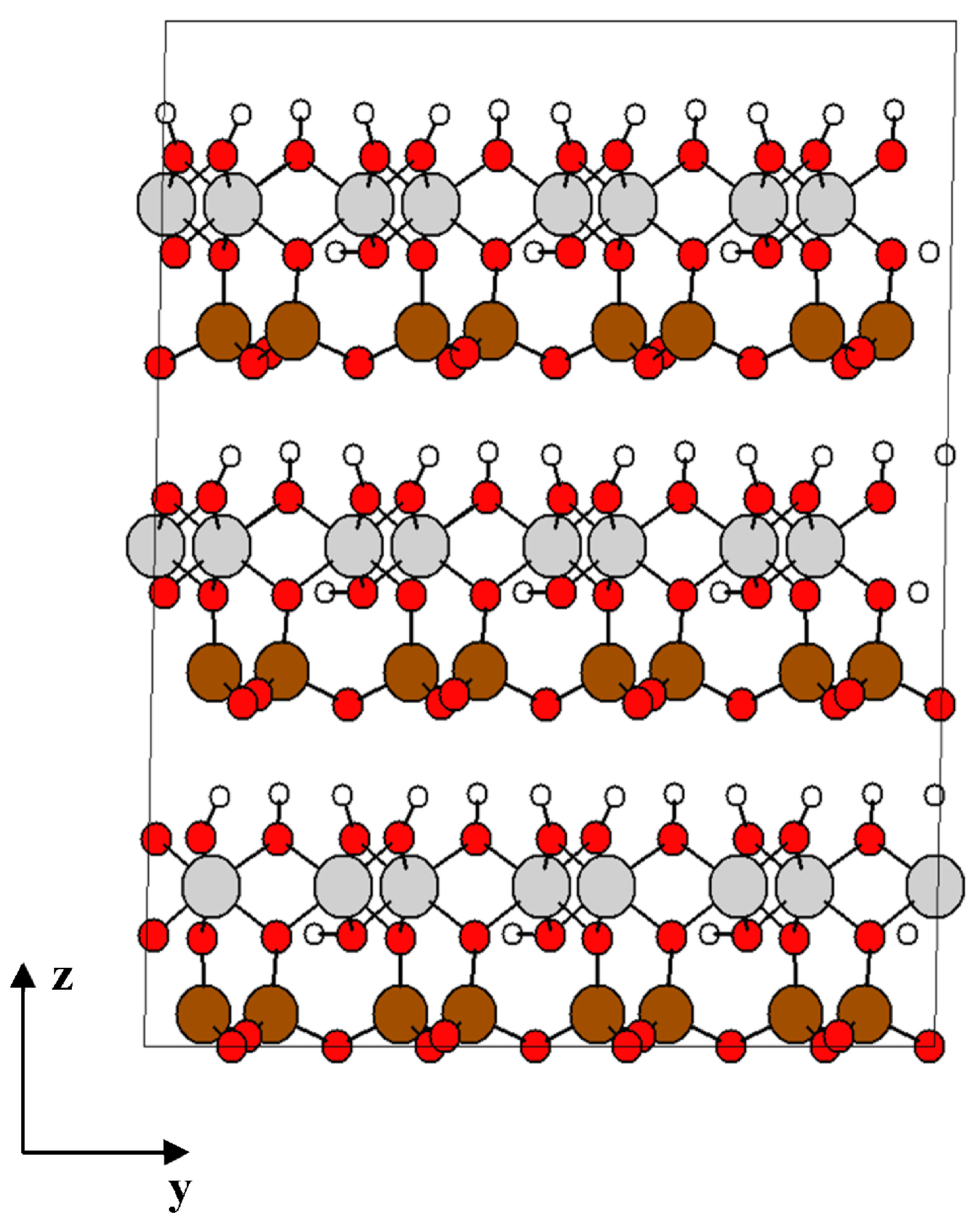
The atomic structure of kaolinite clay is the same as that described in our previous study [9]. The structure of kaolinite shown in Figure 1 is originally based on crystallographic data from Bish et al. [28], a unit cell of triclinic symmetry with lattice parameters a = 5.153 Å, b = 8.941 Å, c = 7.390 Å, and angles: α = 91.926°, β = 105.046°, γ = 89.797°. The basal distance (thickness) of the unit layer is d = 7.1329 Å. The chemical composition of unit cell is 2[Si2Al2O5(OH)4], which corresponds to 34 atoms, and its density is 2.6 g/cm3.
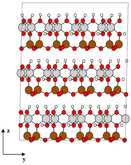
Figure 1.
Structure of kaolinite formed by 4 × 2 × 3 unit cells. O atoms are in red, the tetrahedral Si atoms in brown, octahedrally coordinated Al atoms are in grey, and H atoms are white. Projection view along the ZY-direction.
The simulation box used in our calculations is 4 × 2 × 3 unit cells in dimensions a, b, and c (24 kaolinite unit cells), with a total of 816 atoms in the solid. The corresponding Lx, Ly, and Lz dimensions are 20.614 Å, 17.881 Å, and 22.739 Å. Periodic boundary conditions are applied in all three directions.
The potential energy of a simulated system includes the non-bonded energy and the bonded energy. The non-bonded energy components are Coulomb interactions and short-range van der Waals energy.
The first non-bonded energy term (Coulomb interactions) varies just like the inverse of the bond length between the i and j ions (rij). The following equation shows this energy:
where qi and qj represent the charge of ion i and j respectively, derived from quantum mechanics calculations, e is the electron charge, and εo is the dielectric permittivity of vacuum (8.85419 × 10⁻¹² F/m).
The second non-bonded energy term (van der Waals interactions) presents the interaction between the two non-bonded atoms, represented by the conventional Lennard–Jones (12-6) function, and it includes the short-range repulsion associated with the increase in energy as the two atoms approach each other (Urep), the attractive term energy, (Uattr), and the London dispersion forces:
where Do and Ro are the empirical parameters derived from the fitting of the model; this is equivalent to the dissociation energy and equilibrium atomic separation, respectively.
The parameters of van der Waals between the interaction of two atoms are calculated in accordance with the arithmetic and the geometric mean rules for the distance parameter, Ro, and the energy parameter, Do, respectively [29].
The values of the non-bonded interaction parameters are given in Table 1. The bonded energy is only used to describe hydroxyl groups. The bond stretch energy of the hydroxyl bond (O-H) can be described by a harmonic (simple quadratic) expression:
where k1 is an empirical force constant, ro is the equilibrium bond length, r is the atom–atom separation distance. The values for the CLAYFF-bonded parameters for hydroxyl interactions are given in Table 2.

Table 1.
Non-bonded parameters for the CLAYFF Force Field.

Table 2.
Bonded parameters for the CLAYFF Force Field.
Molecular dynamics calculations at the thermodynamic equilibrium were performed using Nosé–Hoover method in the DL_POLY code, developed in Daresbury Laboratory [30].
The ensembles used in most MD simulations are isothermal–isobaric (NPT), micro-canonical (NVE), canonical (NVT), and grand-canonical (μVT), where the variables N, P, T, V, E, and μ represent, respectively, the number of particles, the pressure, the temperature, the volume, the energy, and the chemical potential. In this work, the standard ensembles implemented are the NPT (the number of particles N, the pressure P, and the temperature T are fixed) with barostat and thermostat relaxation times of 0.5 and 0.5 ps, respectively; and, in the second calculation, the NVE (the number of particles N, the volume V, and the energy E are fixed during the simulation). The Nosé–Hoover thermostat was used to control the temperature [31]. The pressure was kept constant using a Melchionna modification of the Hoover algorithm [32] in which the equations of motion involve a Nosé–Hoover thermostat and a barostat. A thermostat and a barostat were used for the NPT ensemble.
The motion equations were integrated by using the Verlet leapfrog integration algorithm [33,34] with a time step of 1 fs (1 × 10⁻¹⁵ s) and 0.5 fs to ensure the conservation of energy. The Ewald summation technique [35] is considered as the most satisfactory method for treating these Coulombic long-range interactions, using a tolerance of 1 × 10⁻⁵. For short-range interactions, either spherical or “minimum image” cutoff criteria are commonly used [29,34]. The cutoff radius rc = Lx/2, where Lx is the smallest box length (Lx = 1.788 nm). For van der Waals interactions, the cutoff used is between 0.8 and 0.85 nm.
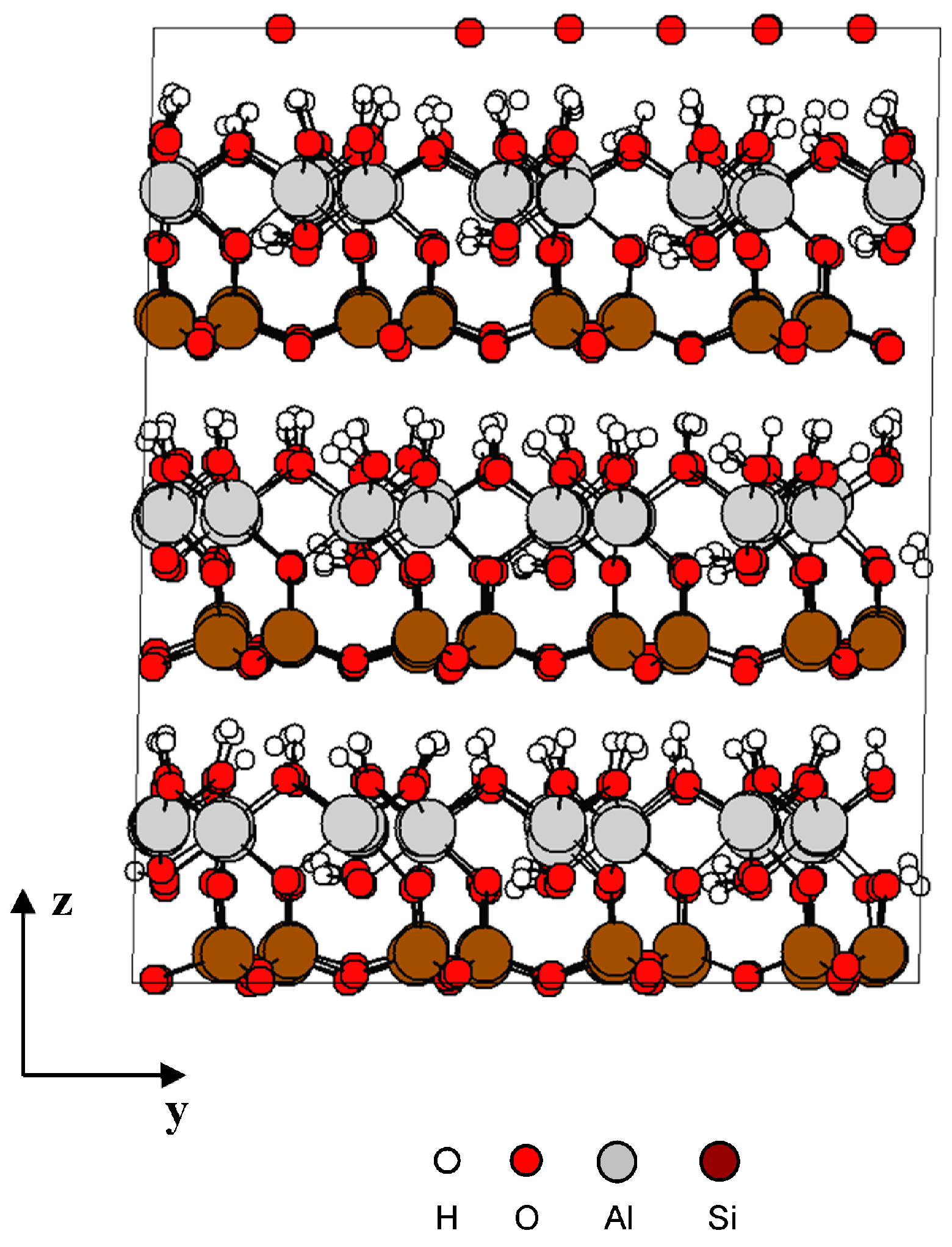
Different samples (solid structure) were prepared at 200 picosecond (ps) using equilibration NPT MD simulation and performed at atmospheric pressure 0.1 MPa [9], 1 GPa, 5 GPa, and 10 GPa at 300 K. Figure 2 shows the kaolinite structure at 0.1 Mpa after equilibration.
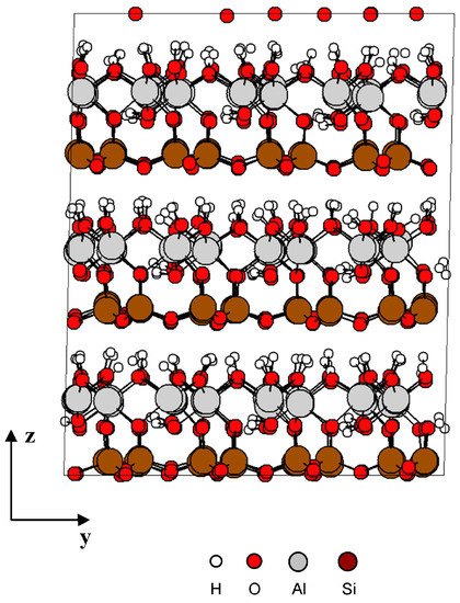
Figure 2.
Kaolinite structure after equilibration NPT MD simulation.
Z-Method to Quantify Melting
The Z-method [15,16] is used to find the melting temperature ™ and superheating limit temperature (TLS) of kaolinite clay. The temperature of melting occurs when the Gibbs free energies of the solid and liquid phases are equal, as shown in the calculations of Morris et al. [36]. Unlike the two-phase (also called co-existence) method, molecular dynamics simulations, the Z-method uses single-phase (solid). The Z-method takes its name from the characteristic shape of the isochoric curve. In this work, the calculations have been achieved in the NVE (N number of atoms, volume V, energy E) ensemble. The volume remains fixed throughout the isochoric curve.
The isochore consists of three branches (See the figure below with the Z curve). The first is crystalline (the solid branch). It can be seen that, before arriving at the temperature limit of superheating (TLS), the structure remained solid because the system of interaction of atoms is equilibrating when the initial kinetic energy is low, and then as this energy starts to increase with T, the system approaches and enters in the superheated solid phase across the melting curve. With all these different temperatures, we obtain an almost straight line to the point of TLS, which is the upper cap of the letter Z.
A second branch with negative slope is a transition from a crystalline state to a liquid state. Once TLS isochore is reached, the temperature drops to Tm due to the latent heat of melting (i.e., the energy required to change the phase of a substance from solid to liquid) being removed from the kinetic energy. This part is called the intermediate branch that starts with TLS and ends with Tm, which is a discontinuity in the straight line. Finally, once the temperatures are above Tm, the system begins to be liquid and then forms an almost straight line (a liquid branch) that is the lower cap of the letter Z.
Therefore, the point at the end of the solid branch represents the temperature limit of superheating, TLS, and the first point which is at the beginning of the curve is the melting temperature, Tm. All details regarding this method are provided in the works of Belonoshko et al. [15,16].
3. Results and Discussion
In a previous work, we have determined the melting point and the temperature limit of superheating at pressure, using the Z-method [9]. Here, we will determine the melting and superheating limit curves.
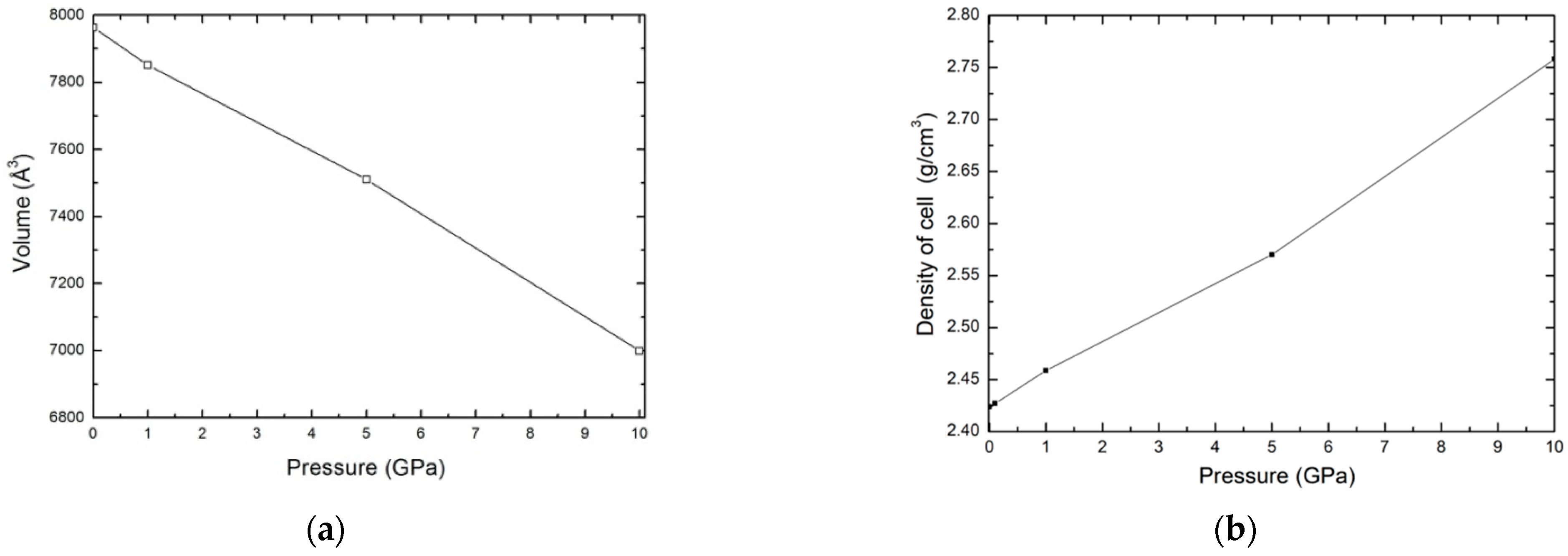
In the first time, the sample was equilibrated with the NPT ensemble. We performed simulations to obtain the variation of volume and density of the kaolinite structure as a function of pressure, P, for a temperature T = 300 K. For a given pressure, the points obtained corresponding to volume and density are shown in Figure 3a,b, respectively. We may see that the density of kaolinite structure increases with increasing pressure.
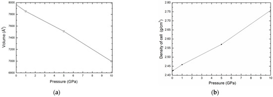
Figure 3.
Variation of the volume (a) and the density (b) as function pressure.
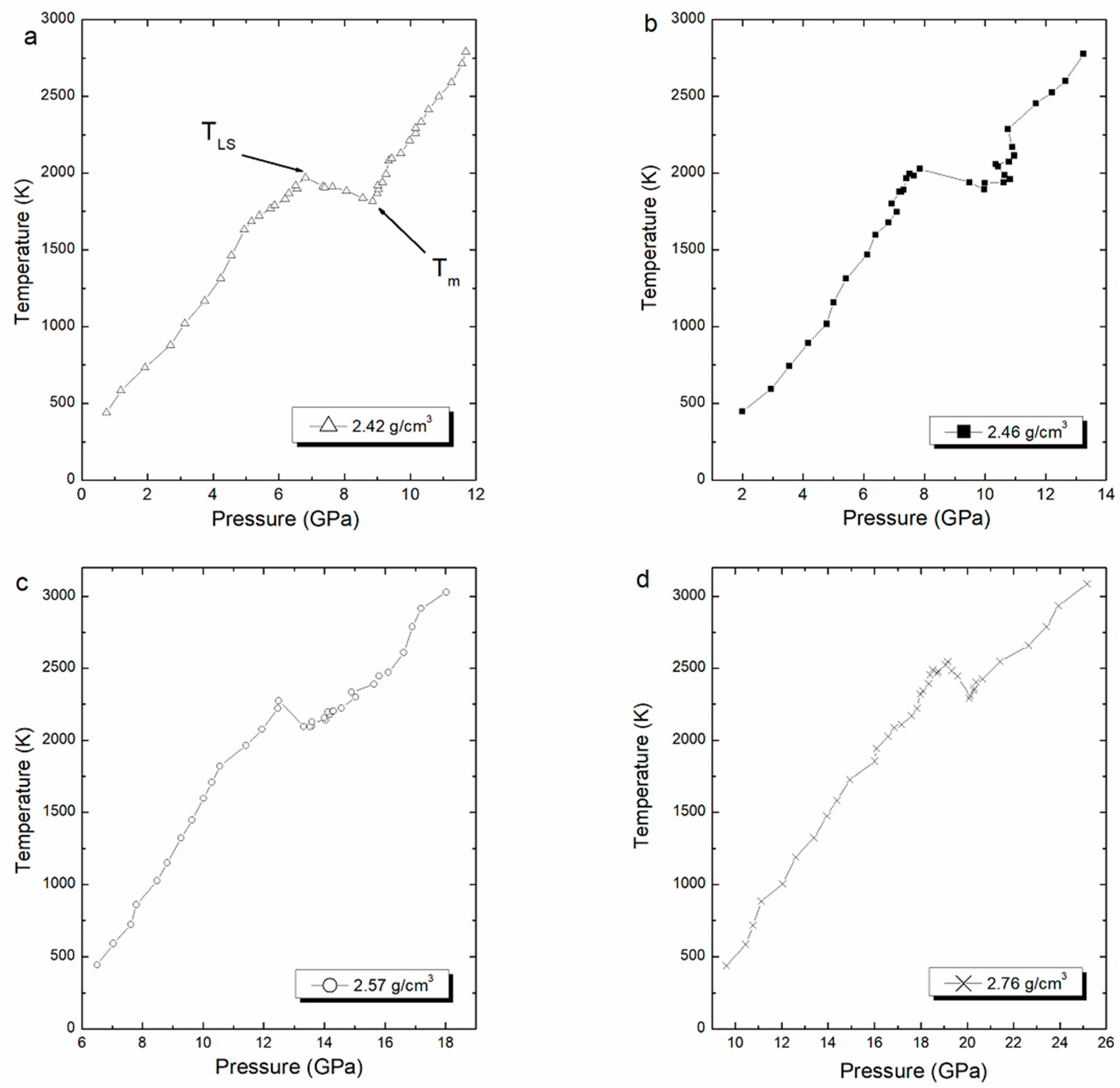
Thereafter, we performed the Z-method simulations, and the computed isochore for each density is shown in Figure 4. This figure shows the melting curve with pressure corresponding to different densities. Each (pressure, temperature) point in the isochoric curve was obtained in the NVE ensemble after performing 800,000 time steps, equivalent to 400 ps.
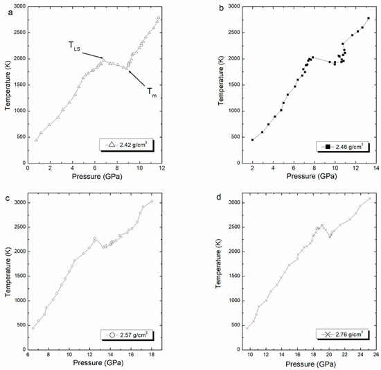
Figure 4.
Computed isochore curves for ρ = 2.42 (a), 2.46 (b), 2.57 (c), and 2.76 (d) g/cm3, with to the corresponding melting points and superheating limit temperature.
The melting point is estimated at the lowest point of the liquid branch, while the superheated limit temperature is estimated at the highest point in the solid branch. The averaged values of superheated limit temperature and the melting point are shown in Table 3. The obtained melting point values are compared with the unique experimental value given by Murray equal to 2123 K [5]. The limit of superheating values is clearly in good agreement with values of temperature superheating calculated using MD calculations in the NVT ensemble given by Benazzouz and Zaoui [8]. The superheating temperature simulated are given between 1990 K and 2550 K in pressures ranging from 6 GPa to 20 GPa [8].

Table 3.
Melting point and superheating limit temperature values for kaolinite with pressure and the percentage between Tm and TLS.
The limit superheated temperature, TLS, is higher than the melting temperature, Tm, in good agreement with a previous work of [15]. In Table 3, we present a percentage of this difference.
In order to confirm the behaviour of the solid superheating limit temperature, TLS, and the behaviour of liquid at the melting temperature, Tm, various properties were measured such as the radial distribution function (g (rij)), coordination numbers (n (rij)), and mean square displacement (MSD) at different temperatures. The radial distribution function for the various atom–atom pairs is a measure and a good indicator to determine the correlation between atoms within a system. To calculate the RDF between the atoms, we use the following expression:
where ρj is the number density of particles of type j in the system and dnij is the number of particles of type j situated in a spherical layer of thickness dr at distance r from a particle of type i. The coordination number of particles of type j around a particle of type i gives the value of the following integral.
where ρj is the number density of the atoms of type j.
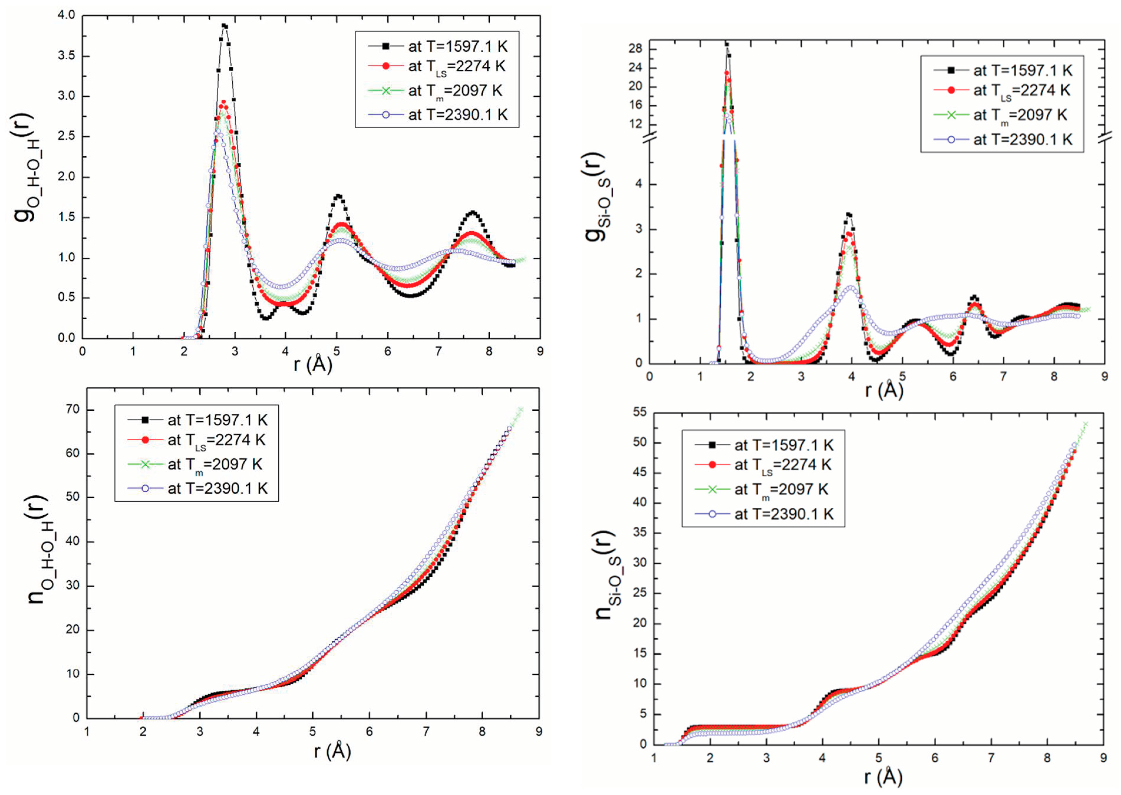
Radial distribution functions (RDF) and coordination number, n(r), were calculated for all atom pairs. As an example of this, the Si-O_S (silicon—surface oxygen) and O_H-O_H (oxygen—oxygen) RDF with temperature and their related coordination numbers are presented in Figure 5. In this figure, we show the RDF for density ρ = 2.57 g/m3 (P = 13.32 GPa) at different temperatures 1597.1 K, TLS = 2274 K, 2097 K, Tm = 1818 K, and 2390.1 K corresponding to temperatures on the solid branch, the superheating limit temperature, the melting point and the temperature on the branch liquid, respectively. These results are compared to those obtained from the DM calculations using the Z-method [9].
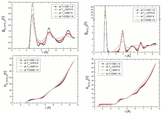
Figure 5.
Si-O_S and O_H-O_H RDF with temperature and their related coordination numbers for ρ = 2.57 g/m3.
The first peak, corresponding to the shortest distance between two neighbouring atoms, decreases with increasing temperature. This phenomenon is repeated and is clearly perceptible in the figures for the pairs of atoms. It explains the differences in structure and the liquid state of the structure of kaolinite at the melting point.
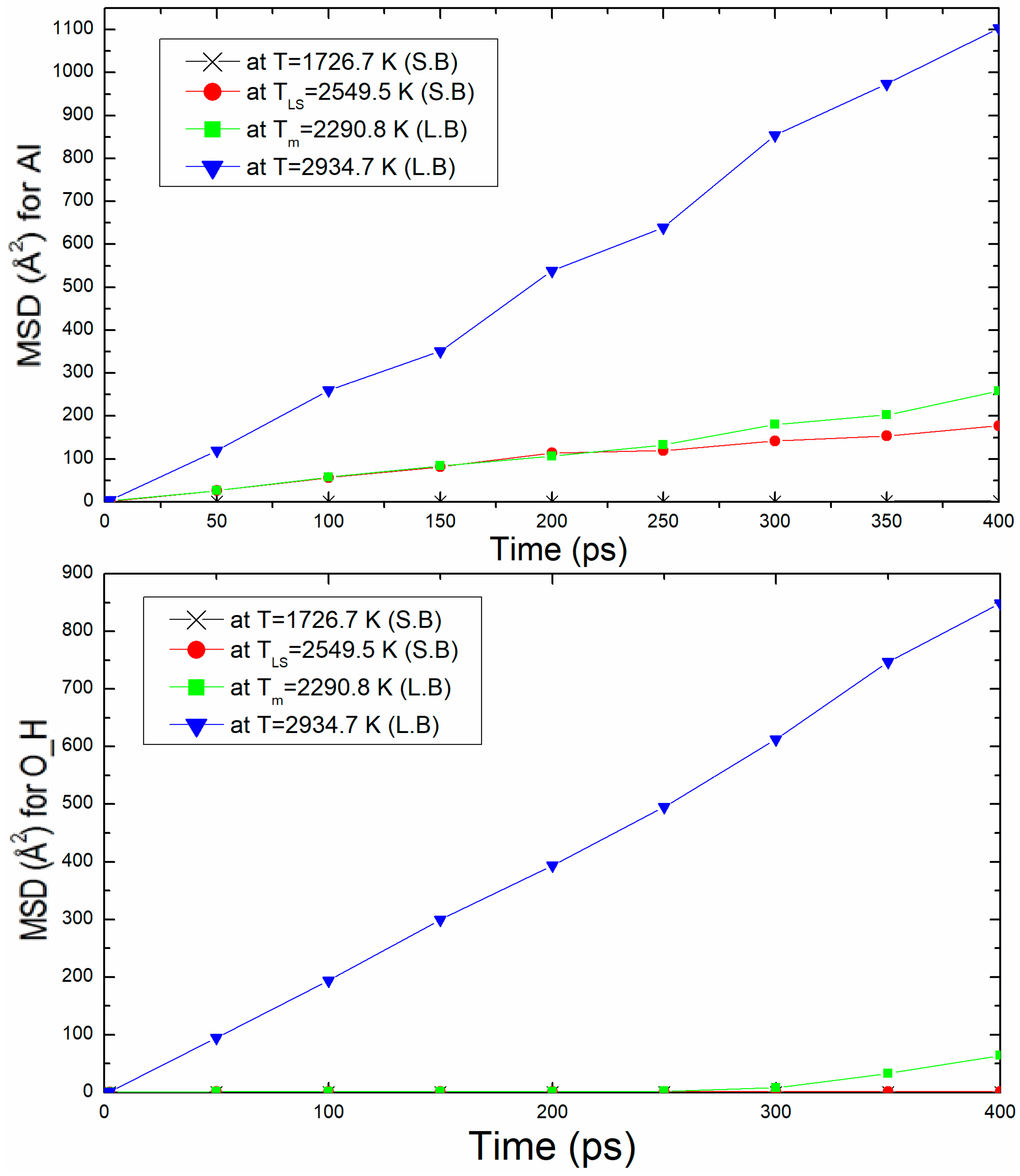
The second properties calculation used to confirm the liquid structure of kaolinite at the melting temperature is mean square displacement (MSD). Figure 6 shows the mean square displacement plotted as function of time (up to 400 ps) for density ρ = 2.76 g/m3 at 20.07 GPa. This figure presents the MSD of two examples Al and O_H atoms at T = 1726.7 K (solid branch), TLS = 2549.5 K, Tm = 2290.9 K, and T = 2934.7 K (liquid branch). The MSD slop at Tm is more important than TLS. It can be noticed that for Al and O_H atoms at T ≥ Tm (liquid branch), the MSD increases rapidly with time, which explains certainly the liquid state of the structure. In the solid branch, the MSD at T = 1726.7 K and TLS = 2549.5 K increases but with a low value (slopes less weak) for O_H atom.
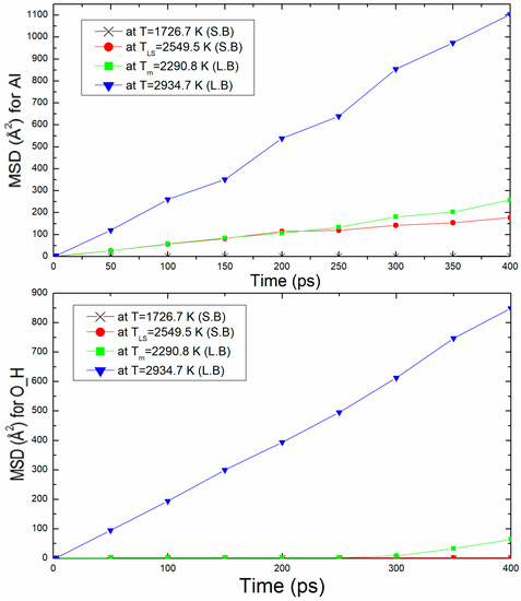
Figure 6.
Mean square displacement, MSD, of Al and O_H atoms with time for ρ = 2.76 g/m3.
The diffusion coefficients are calculated to complete the characterisation of the solid and liquid states obtained. The diffusion coefficients of all atoms, Al, Si, O_A (apical oxygen), O_S (surface oxygen), O_H (hydrogen oxygen), and H were computed. The diffusion coefficient, D, is related with the MSD by Einstein expression according to:
where ri(0) and ri(t) are the initial and final positions of the centre of mass of the particle at time t, and <|ri(t) − ri(0)|2> is the mean square displacement (MSD) averaged over the ensemble. The diffusion coefficient is calculated graphically from the slope of MSD versus time.
As we may see, the diffusion coefficient is significantly higher in the liquid branch than in the solid branch. A significant increase in the diffusion coefficient is noticed in the liquid isochore branch. Table 4 shows the diffusion coefficient values for all atoms, Al, Si, O_A, O_S O_H, and H at different temperatures for ρ = 2.76 g/m3. The value of its diffusion coefficient for Al in the liquid isochore branch obtained from the slope of MSD in Figure 6, D = 4.73 × 10⁻⁹ m2/s, is in good agreement with those obtained for the liquid diffusion.

Table 4.
Values of diffusion coefficient for all atoms, Al, Si, O_A, O_S O_H, and H at different temperatures.
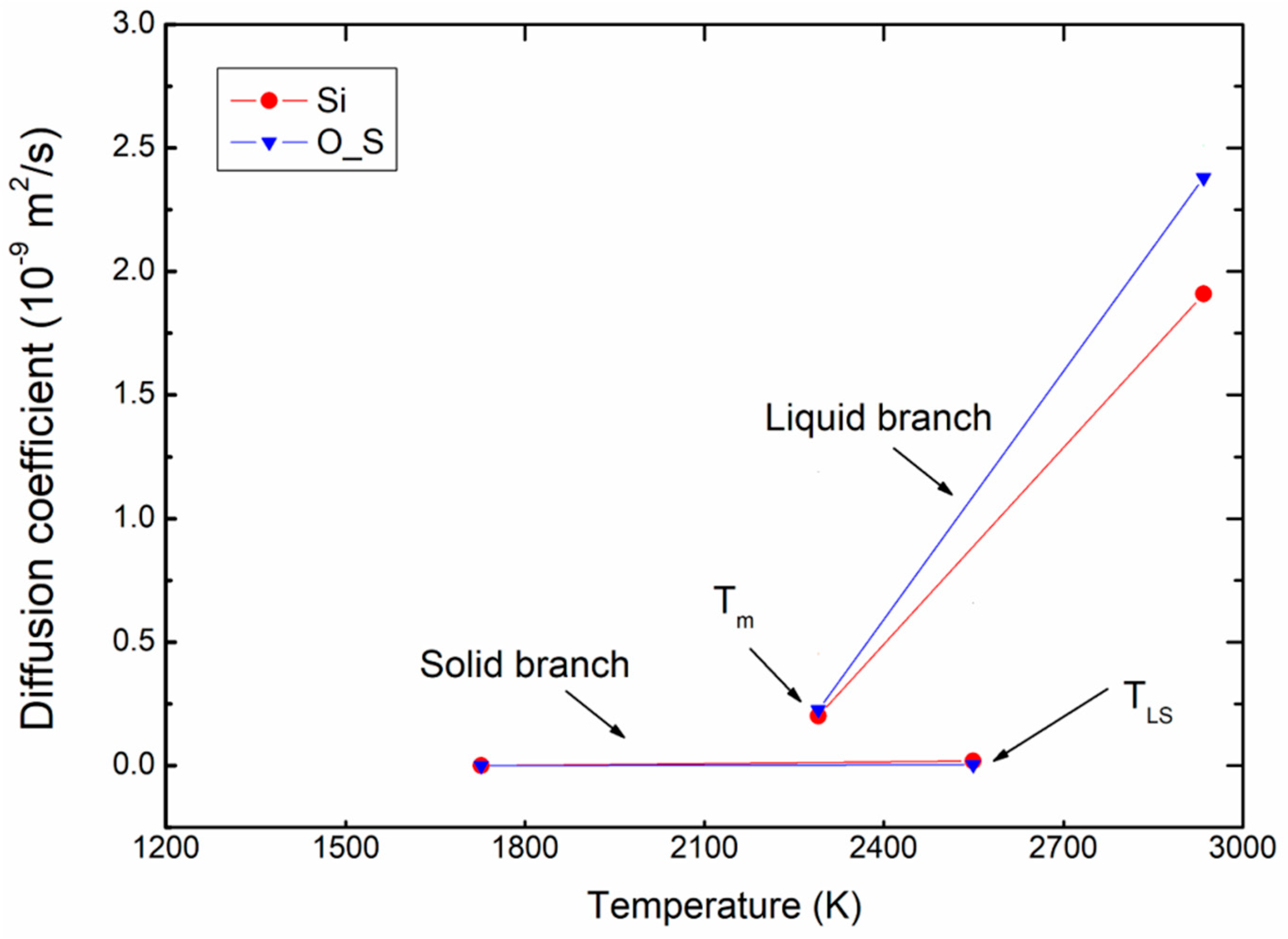
Figure 7 presents an example of the variation of diffusion coefficient for Si and O_S atoms as function of temperature for ρ = 2.76 g/m3. Here, it can be seen that the difference in diffusion is clear; the diffusion coefficient is much higher in the liquid branch than in the solid branch. In the solid blanch, the diffusion coefficients are almost zero because the atoms in a solid cannot diffuse away from their equilibrium positions, compared to those of the liquid branch.
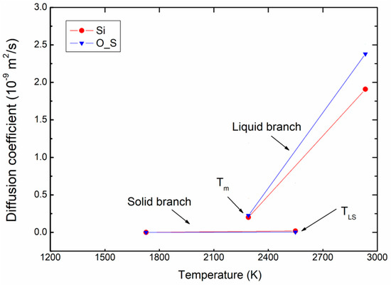
Figure 7.
Variation of diffusion coefficient for atoms with increasing of temperature for ρ = 2.76 g/m3.
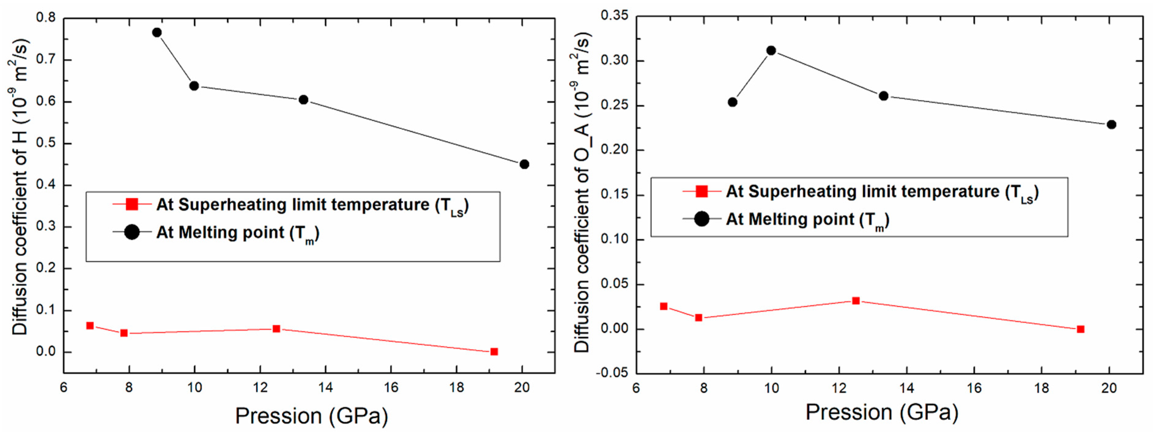
The variation of the diffusion coefficient for O_A and H atoms as function of pressure is shown in Figure 8. The diffusion coefficient decreases with pressure. There is a difference between the values of diffusion at the superheating limit temperature and at the melting point. The diffusion coefficient of these atoms at Tm is greater than the one at TLS by a factor larger than 8. This can be used to confirm once more the liquid phase at Tm.
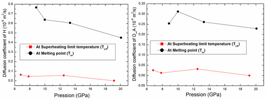
Figure 8.
Variation of the diffusion coefficient of O_A and H atoms as function of pressure.
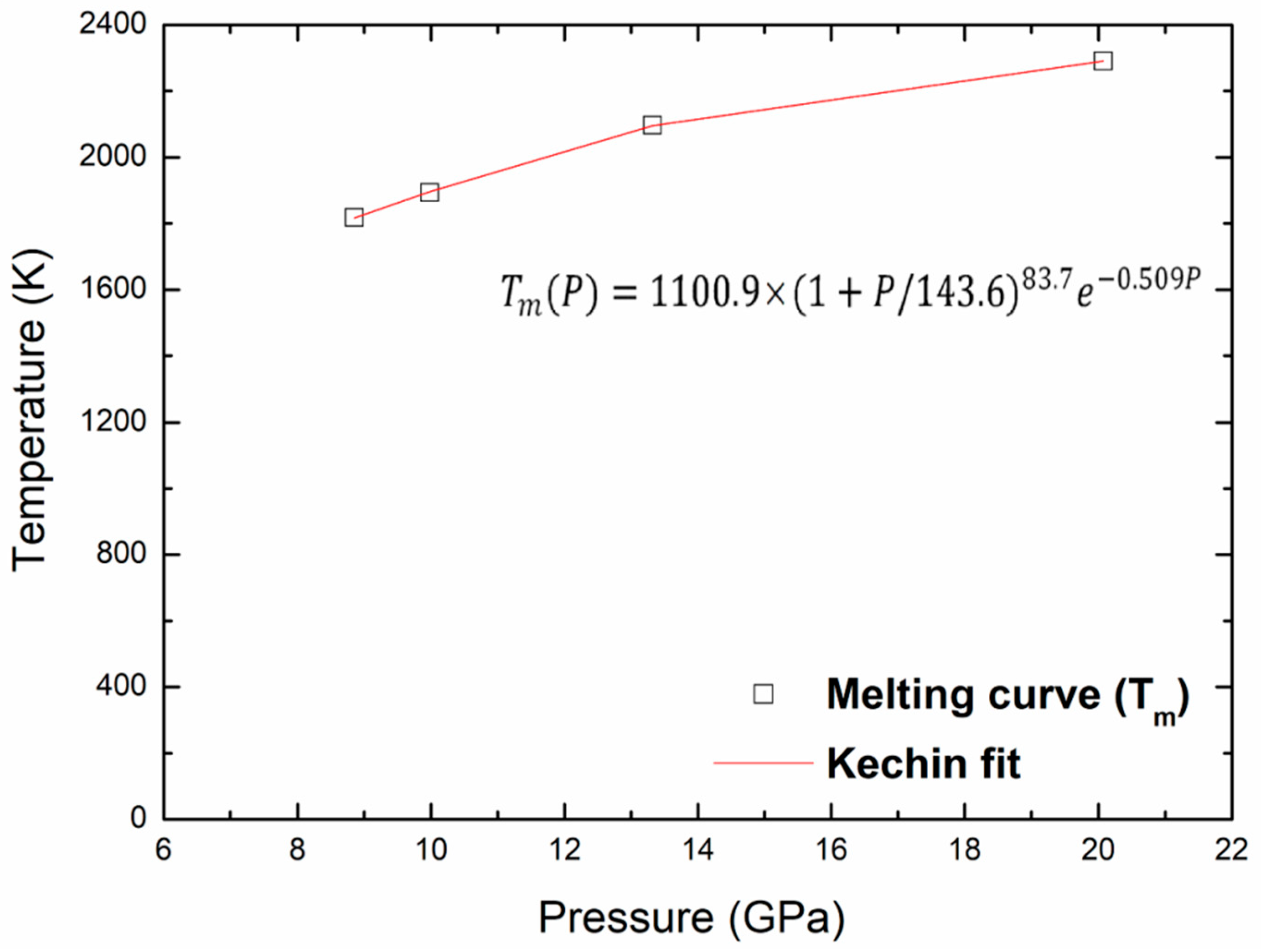
Finally, the points of the melting curve obtained in this work were fitted using a unified equation, proposed by Kechin for the melting curve at high pressure [36,37]. The melting equation is given as follows:
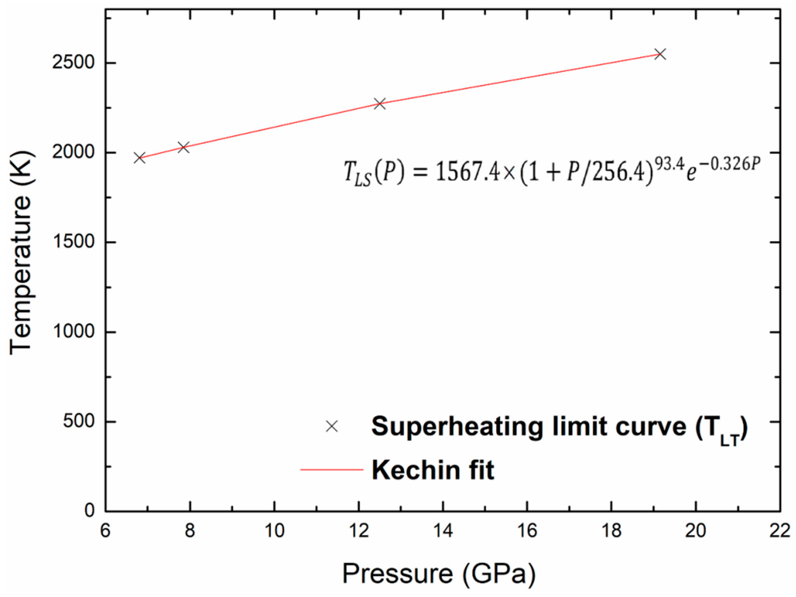
where P is the pressure, Tm(P) is the melting temperature at this pressure, and T0 is the melting point at zero pressure. The values of the fitted parameters (T0, a, b and c) corresponding to melting are given in Table 5. Figure 9 shows the melting curve with the pressure up to 20 GPa and the Kechin fit curve of these points. There is no experimental nor theoretical melting curves to compare with our present work. We may determine the melting points, Tm, at any pressure, the melting point at zero pressure, T0, equal to 1100.9 K. The same equation is used to fit the superheating limit temperature curve as shown in Figure 10. The fitted parameters for the Kechin equation are given in Table 5.

Table 5.
Fitted parameters for the Kechin equation.
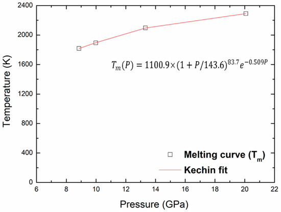
Figure 9.
Melting and Kechin fit curves for kaolinite up to 20 Gpa.
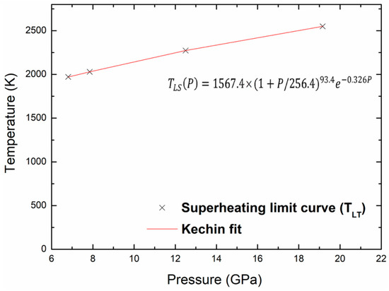
Figure 10.
Superheating limit temperature and Kechin fit curves for kaolinite with pressure.
4. Conclusions
In summary, we have calculated the melting point and the superheating limit temperature of kaolinite clay for different densities using the Z-method based on classical molecular dynamics simulation by means of the CLAYFF force field. These important values have been deduced from the simulated isochore (PT) in the microcanonical, NVE, ensemble at different pressures. The obtained melting points, Tm, are 1893 K, 2096.9 K, and 2290.9 K corresponding to the pressures 9.98 GPa, 13.32 GPa, and 20.07 GPa, respectively. The obtained superheating limit temperatures TLS are 2029 K, 2273.9 K, and 2549.5 K related to pressures 7.85 GPa, 12.5 GPa, and 19.15 GPa, respectively. Several measurable quantities, such as the radial distribution function, coordination numbers, mean square displacement, and diffusion coefficients, were used to confirm melting and superheating temperatures in the isochore curve. Finally, the melting and superheating limit curves were plotted for kaolinite clay and their corresponding melting equations were proposed. These melting and superheating limit equations are given as follows: and , respectively.
Author Contributions
Conceptualization, B.K.B. and A.Z.; methodology, B.K.B. and A.Z.; software, B.K.B.; validation, B.K.B. and A.Z.; formal analysis, B.K.B. and A.Z.; investigation, B.K.B. and A.Z.; resources, B.K.B.; data curation, B.K.B.; writing—original draft preparation, B.K.B. and A.Z.; writing—review and editing, B.K.B. and A.Z., visualization, B.K.B.; supervision, A.Z.; project administration, A.Z.; funding acquisition, A.Z. All authors have read and agreed to the published version of the manuscript.
Funding
This research received no external funding.
Data Availability Statement
Not applicable.
Conflicts of Interest
The authors declare no conflict of interest.
References
- Ranjbar, N.; Kuenzel, C.; Gundlach, C.; Kempen, P.; Mehrali, M. Halloysite reinforced 3D-printable geopolymers. Cem. Concr. Compos. 2023, 136, 104894. [Google Scholar] [CrossRef]
- Hasany, M.; Thakur, A.; Taebnia, N.; Kadumudi, F.B.; Shahbazi, M.-A.; Pierchala, M.K.; Mohanty, S.; Orive, G.; Andresen, T.L.; Foldager, C.B. Combinatorial screening of nanoclay-reinforced hydrogels: A glimpse of the “holy grail” in orthopedic stem cell therapy? ACS Appl. Mater. Interfaces 2018, 10, 34924–34941. [Google Scholar] [CrossRef] [PubMed]
- Pierchala, M.K.; Kadumudi, F.B.; Mehrali, M.; Zsurzsan, T.-G.; Kempen, P.J.; Serdeczny, M.P.; Spangenberg, J.; Andresen, T.; Dolatshahi-Pirouz, A. Soft electronic materials with combinatorial properties generated via mussel-inspired chemistry and halloysite nanotube reinforcement. ACS Nano 2021, 15, 9531–9549. [Google Scholar] [CrossRef] [PubMed]
- Murray, H.H. Traditional and new applications for kaolin, smectite, and palygorskite: A general overview. Appl. Clay Sci. 2000, 17, 207. [Google Scholar] [CrossRef]
- Murray, H.H. Applied Clay Mineralogy, Occurrences, Processing and Application of Kaolins, Bentonites, Palygorskite- Sepiolite, and Common Clays. Dev. Clay Sci. 2007, V2, 180. [Google Scholar]
- Lee, S.; Kim, Y.J.; Moon, H.S. Phase Transformation Sequence from Kaolinite to Mullite Investigated by an Energy-Filtering Transmission Electron Microscope. J. Am. Ceram. Soc. 1999, 82, 2841–2848. [Google Scholar] [CrossRef]
- Benazzouz, B.K.; Zaoui, A. Thermal behaviour and superheating temperature of Kaolinite from molecular dynamics. Appl. Clay Sci. 2012, 58, 44–51. [Google Scholar] [CrossRef]
- Benazzouz, B.K.; Zaoui, A. Phase diagram of kaolinite from Molecular Dynamics calculations. Phys. B Condens. Matter 2012, 407, 2462–2470. [Google Scholar] [CrossRef]
- Benazzouz, B.K.; Zaoui, A.; Belonoshko, A.B. Determination of the melting temperature of kaolinite by means of the Z-method. Am. Mineral. 2013, 98, 1881–1885. [Google Scholar] [CrossRef]
- Chakraborty, A.K. Phase Transformations of Kaolinite Clay; Springer: New Delhi, India, 2014; pp. 3–12, 43–47, 185–206, 327–329. [Google Scholar]
- Cheng, Y.; Xing, J.; Bu, C.; Zhang, J.; Piao, G.; Huang, Y.; Xie, H.; Wang, X. Dehydroxylation and Structural Distortion of Kaolinite as a High-Temperature Sorbent in the Furnace. Minerals 2019, 9, 587. [Google Scholar] [CrossRef]
- Matsui, M.; Price, G.D. Simulation of the pre-melting behaviour of MgSiO3 perovskite at high pressures and temperatures. Nature 1990, 1351, 735–737. [Google Scholar] [CrossRef]
- Belonoshko, A.B. Molecular dynamics of MgSiO3 perovskite at high pressures: Equation of state, structure, and melting transition. Geochim. Cosmochim. Acta 1994, 58, 4039–4047. [Google Scholar] [CrossRef]
- Chaplot, S.L.; Choudhury, N.; Rao, K.R. Molecular dynamics simulation of phase transitions and melting in MgSiO3 with the perovskite structure. Am. Mineral. 1998, 83, 937–941. [Google Scholar] [CrossRef]
- Belonoshko, A.B.; Skorodumova, N.V.; Rosengren, A.; Johansson, B. Melting and critical superheating. Phys. Rev. 2006, 73, 012201. [Google Scholar] [CrossRef]
- Belonoshko, A.B.; Davis, S.; Skorodumova, N.V.; Lundow, P.H.; Rosengren, A.; Johansson, B. Properties of the fcc Lennard-Jones crystal model at the limit of superheating. Phys. Rev. 2007, 76, 064121. [Google Scholar] [CrossRef]
- Belonoshko, A.B.; Burakovsky, L.; Chen, S.P.; Johansson, B.; Mikhaylushkin, A.S.; Preston, D.L.; Simak, S.I.; Swift, D.C. Molybdenum at High Pressure and Temperature: Melting from Another Solid Phase. Phys. Rev. Lett. 2008, PRL 100, 135701. [Google Scholar] [CrossRef]
- Davis, S.M.; Belonoshko, A.B.; Johansson, B.; Rosengren, A. An Atomistic Model for Homogeneous Melting. Available online: https://www.diva-portal.org/smash/record.jsf?pid=diva2%3A234456&dswid=-6410 (accessed on 20 April 2023).
- Burakovsky, L.; Chen, S.P.; Preston, D.L.; Belonoshko, A.B.; Rosengren, A.; Mikhaylushkin, A.S.; Simak, S.I.; Moriarty, J.A. High-Pressure—High-Temperature Polymorphism in Ta: Resolving an Ongoing Experimental Controversy. Phys. Rev. Lett. 2010, 104, 255702. [Google Scholar] [CrossRef]
- Gonzalez-Cataldo, F.; Davis, S.; Gutiérrez, G.Z. method calculations to determine the melting curve of silica at high pressures. J. Phys. Conf. Ser. 2016, 720, 012032. [Google Scholar] [CrossRef]
- Anzellini, S.; Errandonea, D.; Burakovsky, L.; Proctor, J.E.; Beavers, C.M. Characterization of the high-pressure and high-temperature phase diagram and equation of state of chromium. Sci. Rep. 2022, 12, 6727. [Google Scholar] [CrossRef]
- Cygan, R.T.; Liang, J.J.; Kalinichev, A.G. Molecular Models of Hydroxide, Oxyhydroxide, and Clay Phases and the Development of a General Force Field. Phys. Chem. 2004, 108, 1255–1266. [Google Scholar] [CrossRef]
- Kalinichev, A.G.; Wang, J.; Kirkpatrick, R.J. Molecular dynamics modeling of the structure, dynamics and energetics of mineral–water interfaces: Application to cement materials. Cem. Concr. Res. 2007, 37, 348–350. [Google Scholar] [CrossRef]
- Larentzos, J.P.; Greathouse, J.A.; Cygan, R.T. An ab Initio and Classical Molecular Dynamics Investigation of the Structural and Vibrational Properties of Talc and Pyrophyllite. J. Phys. Chem. 2007, 111, 12752–12759. [Google Scholar] [CrossRef]
- Mazo, M.A.; Manevitch, L.I.; Gusarova, E.B.; Shamaev, M.Y.; Berlin, A.A.; Balabaev, N.K.; Rutledge, G.C. Molecular Dynamics Simulation of Thermomechanical Properties of Montmorillonite Crystal. 1. Isolated Clay Nanoplate. J. Phys. Chem. 2008, 112, 2964–2969. [Google Scholar] [CrossRef]
- Ebrahimi, D.; Pellenq, R.J.-M.; Whittle, A.J. Simulation of hydration and elastic properties of montmorillonite using molecular dynamics, Multiscale and Multiphysics Processes in Geomechanics. In Multiscale and Multiphysics Processes in Geomechanics: Resultsof the Workshop on Multiscale and Multiphysics Processes in Geomechanics, 23–25 June 2010; Springer: Berlin/Heidelberg, Germany, 2011; pp. 105–108. [Google Scholar]
- Cygan, R.T.; Greathouse, J.A.; Kalinichev, A.G. Advances in Clayff Molecular Simulation of Layered and Nanoporous Materials and Their Aqueous Interfaces. J. Phys. Chem. 2021, 125, 17573–17589. [Google Scholar] [CrossRef]
- Bish, D.L. Rietveld Refinement of the Kaolinite Structure at 1.5 K. Clays Clay Miner. 1993, 41, 738–744. [Google Scholar] [CrossRef]
- Frenkel, D.; Smit, B. Understanding Molecular Simulation; Academic Press: San Diego, CA, USA, 1996. [Google Scholar]
- Smith, W.; Forester, T.J. The DL_POLY molecular simulation package. Mol. Graphics. 1996, 14, 136. [Google Scholar] [CrossRef]
- Hoover, W.G. Equilibrium phase-space distributions. Phys. Rev. 1985, 31, 1695. [Google Scholar] [CrossRef]
- Melchionna, S.; Ciccotti, G.; Holian, B.L. Hoover NPT dynamics for systems varying in shape and size. Molec. Phys. 1993, 78, 533. [Google Scholar] [CrossRef]
- Verlet, L. Computer “Experiments” on Classical Fluids. I. Thermodynamical Properties of Lennard-Jones Molecules. Phys. Rev. 1967, 159, 98. [Google Scholar] [CrossRef]
- Allen, M.P.; Tildesley, D.J. Computer Simulation of Liquids; Clarendon: Oxford, UK, 1987. [Google Scholar]
- Ewald, P.P. Die Berechnung optischer und elektrostatischer Gitterpotentiale. Ann. Phys. 1921, 64, 253. [Google Scholar] [CrossRef]
- Morris, J.R.; Wang, C.Z.; Ho, K.M.; Chan, C.T. Melting line of aluminum from simulations of coexisting phases. Phys. Rev. 1994, 49, 3109–3115. [Google Scholar] [CrossRef] [PubMed]
- Kechin, V.V. Melting curves equations at high pressure. Phys. Rev. 2001, 65, 052102. [Google Scholar] [CrossRef]
Disclaimer/Publisher’s Note: The statements, opinions and data contained in all publications are solely those of the individual author(s) and contributor(s) and not of MDPI and/or the editor(s). MDPI and/or the editor(s) disclaim responsibility for any injury to people or property resulting from any ideas, methods, instructions or products referred to in the content. |
© 2023 by the authors. Licensee MDPI, Basel, Switzerland. This article is an open access article distributed under the terms and conditions of the Creative Commons Attribution (CC BY) license (https://creativecommons.org/licenses/by/4.0/).

