1. Introduction
Detecting the ball and roller bearing defects in operation and predicting their residual life are key issues of the implementation of the Industry 4.0 approach [
1]. Those activities allow monitoring the bearing health and proceeding easily with a predictive maintenance, through the system prognosis [
2]. Nevertheless, they require resorting to a monitoring system, connected to a remote control center [
3]. This need implies that even testing activity, during product development, performs the machine condition monitoring (MCM), to test sensors, the data acquisition system, rotor-bearing system and the overall elements in advance, before that they are monitored in service. Moreover, some new concepts of smart bearing [
4,
5] gradually rise up, in the literature, as a useful tool for many industrial applications [
1,
6,
7,
8]. The smart bearing system aims at reaching two main goals, i.e., an effective detection of bearing failure, for different operational regimes, as well as a useful monitoring of the machine behavior, through the bearing itself, when possible. This bearing is conceived as a node of a sensor network, for a remote control of system operation [
9]. That use requires designing some new test benches, with augmented capabilities. Typically, they include the possibility of testing even large bearings, used in the industrial machinery, and of setting up the whole monitoring system, in terms of both hardware and software. Those motivations lead to a current need of the industry of designing a compact system for bearing testing and monitoring, to be itself connected to the industrial network. In this paper, the design of such a new test rig is developed. It aims to test middle-sized bearings for industrial application, such as those applied to the rolling mill, for instance. Due to the heavy configuration of tested bearings, the system layout is designed to reduce the impact of actions on supports and the platform, through a sort of self-balancing of actions between bearings, within the rotor system. This test rig implements both the “in-monitoring” (bearing health) and “out-monitoring” (machine condition) activities. The systems engineering approach can drive the description of the design activity, as is described in the following sections, from the customer needs to the test rig construction, as was just accomplished [
10].
2. Customer Needs
Some test rigs for the characterization of the bearing system are already available on the market. They allow the bearing life prediction, but the industry is currently looking for new layouts, aiming to provide additional functions to those already available in the recent past. The larger scale of several special machinery, vehicles and systems motivates to test bearings in the middle- and large-size range, respectively, as defined in the following sections. The scale effect is often a critical issue in material damage, as in fatigue, and thus a direct test on real dimensions may have a beneficial effect in assessing tools and layouts. Moreover, nowadays, a precise measurement of friction torque opposed by bearing to shaft rotation has become more and more useful, to evaluate the system losses and dissipation. The direct measurement of temperature sometimes looks relevant in the design activity, as in service, to warn operators about any anomalous behavior of the monitored machine. The modularity of the test rig is also a significant issue for testing bearings with different layout and size. In the meantime, the test rig must be sufficiently compact to avoid exploiting a large room in the factory. The operators look for a good uncoupling between the factory platform, whose behavior might be affected by vibration and noise, and the test rig. In contrast, the system must avoid applying severe loads on the platform. The monitoring system assures a continuous activity, i.e., it is always active in rotor service, although measurements can be fractioned in some duty cycles, with defined acquisition frequency and sampling time, and able to warn operators against the risk of catastrophic events and the occurrence of adverse agents, such as, for instance, fire, corrosion and noise [
11]. Moreover, the monitoring activity must trace the test rig behavior in operation, as precisely as a simple, light and effective monitoring system does. Finally, to improve the capabilities of each test, a wide use of the enabling technologies proposed by the Industry 4.0 strategy is highly recommended [
12]. Quality, cost and environmental compatibility are all critical issues to be considered in designing the test rig, especially from the perspective of production as a series, in case of homologation for industrial purposes.
3. System Requirements
The customer needs qualitatively describe some design specifications, but a direct traceability between needs and requirements allows the designer to proceed straightforward with several quantitative details. The system is aiming to cope with three main issues, such as bearing scale, measurements and smartness. Functional requirements explore some of these issues. The main goal of the test rig is testing the bearing at different spin speeds, even in transient dynamics, while the rotor is accelerating, decelerating and in either subcritical or supercritical regime [
13], i.e., never in correspondence of an angular speed exciting the system resonance. In the meantime, it monitors some typical parameters such as load, speed, temperature and vibration amplitude and frequency. In some cases, noise is also measured. The monitoring system collects data in operation, through some sensors, and then transfers the related information to an acquisition system, where the elaboration starts, by resorting, in perspective, to some new technologies, such as the machine learning [
14,
15] and the deep learning algorithms [
16]. Monitoring, prognosis and diagnosis are then performed.
Operational requirements help in defining the range of operation. For the typical industrial assets considered in designing this test rig, the spin speed approximately spans from some hundreds of rpm up to approximately 2500 rpm, in industrial machinery supported by roller and ball bearings, although some rotors rotate even faster when contactless supports are applied, for instance, the magnetic bearings [
17]. Temperature is usually kept lower than 120 °C, preferably even at 70–80 °C, and higher than −40 °C. Loads are extremely variable, depending on the specific application. Some kN are often applied in middle-size bearings, up to some hundreds of kN, along the radial and axial direction, respectively, according to the bearing layout [
18]. Oil lubrication typically applies, and huge heating must be prevented, as well as a severe contamination.
Architectural requirements, finally, add information about the system layout. Considering that many test rigs are already exploited to investigate the behavior in medium–small bearings, a typical target for this system looks at monitoring bearings whose outer diameter is larger than 200 mm, up to approximately 450 mm, although this upper limit might be defined case by case, depending on the industrial application analyzed. Power and safety requirements usually lead to huge bearing monitoring test rigs, such as those used for wind energy conversion [
19]. This system shall preferably include two sets of bearings, i.e., one to be tested and one to provide support to the whole rotor system. Actuation along the radial and axial direction, respectively, shall be independent, to allow for uncoupling dynamic effects. The system shall be as modular as possible, to allow for assembling several kinds of bearings, within a given size range. The rotor shall be safely connected to a motor, through a mechanical joint able to uncouple the system rotation from the power source as soon as any accidental failure occurs. It is required that the test rig is constrained to a platform, and some suitable protections avoid any operator’s injury. The lubrication system must be preferably active to avoid heating and keeping contamination as low as possible. The set of sensors must be compatible with structural elements and the layout, to be easily maintained and calibrated. This implies a careful selection of sensors’ technology for a full compatibility with the operational environment, where the system will be located. All these requirements fundamentally describe the needs expressed by the industry, at least for a preliminary design activity.
4. System Architecture
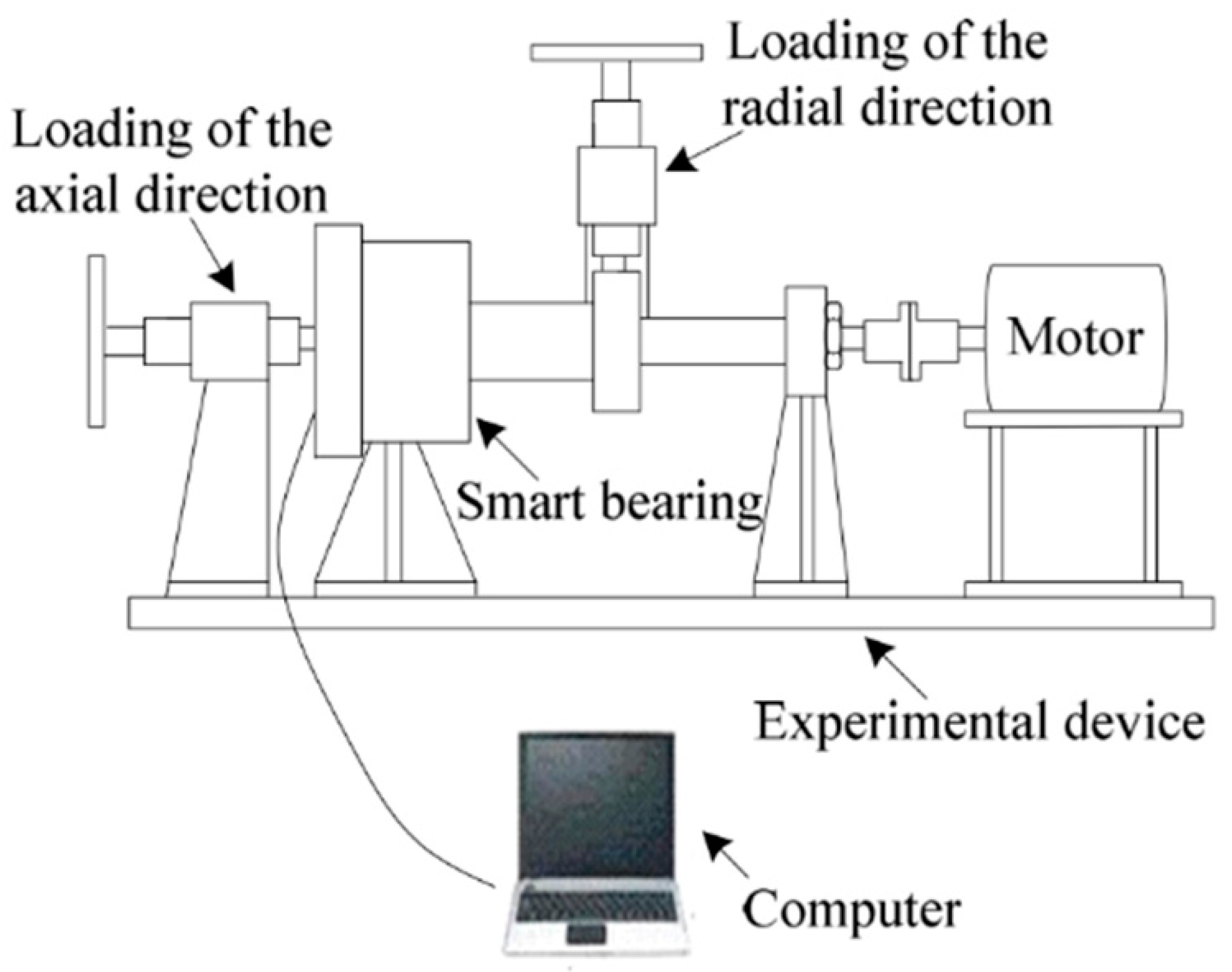
A preliminary screening of typical layouts applied to the design of bearing monitoring systems has been performed. Several test rigs aim at monitoring spin speed, vibration (rotor acceleration along the three axes more than velocity and displacement), noise and only seldom temperature. The real matter of distinction of these layouts concerns the system architecture. To analyze differences among some test rigs, three main functions can be considered as the system power feeding, the bearings’ assembly and loading and the friction torque monitoring, when applied. A typical layout is depicted in
Figure 1.
The rotor is horizontal, and only a main shaft is included. An electric motor applies torque and rotation, through a mechanical coupling. Only two bearings constrain the shaft. One simply supports the rotor, while a second bearing is monitored, eventually being a “smart bearing”, i.e., a bearing equipped with sensors. Actions apply to the rotor-shaft system directly through two external actuators, along the radial and axial direction, respectively. Surely, this architecture looks compact and the minimum number of elements is involved. However, bearings are indirectly loaded through the shaft bending. A relevant load can be applied to the supporting bearing, only used to perform the test, but never monitored. Moreover, if a large load is required on the monitored bearing, a huge action along the radial direction is required on the shaft, thus affecting the overall system response. Loads are transmitted to the platform, and the system might receive some excitations from the platform itself. This configuration can be defined as a mono-axial rotor, with two bearings and speed control. The main differences between layouts, similar to that described in
Figure 1, concern the direction and amplitude of loads, a different approach in applying radial load, the number and position of bearings, the classification of bearings either in support or monitored systems, the motor properties and the strategy of control. The previous layout is quite popular in commercial rotor kits [
20], as in test rigs built for scientific experiments [
21,
22]. For instance, the test rig used by Daga et al. [
21] for high-speed testing of aeronautical bearings presents only a radial load for the single bearing under test, generated horizontally by a sledge for up to 1800 N, while the test rig used by Delprete et al. [
22] is also capable of only applying a radial load through the belt tension to the single damaged bearing under test. This configuration can allow the testing of multiple bearings at the same time, with variable loads in both the radial and axial directions, if a particular design of the loading components of the test rig is implemented. The bearing supporting the shaft typically undergoes the full load applied. Therefore, its dimensions will increase together with the target loads in testing.
Recently, Martin et al. [
23,
24] presented a quite novel smart bearing approach, in which the variation of electric impedance of the bearing is measured via an external electronic circuit and is used to identify the load applied and the angular speed. Some experimental results were obtained using a custom-built test rig, that allows testing four small-size bearings simultaneously, at a rotational speed up to 8000 rpm, with loads up to 40 kN per bearing, both in the radial and axial directions, independently. The vertical radial load is applied by a hydraulic actuator, via the two middle rolling bearings, while the two outer ones support the shaft and transmit actions to the platform.
A second layout often used by industrial and academic laboratories [
25] is described in
Figure 2.
In this case, the main peculiarity is the presence of a main shaft, supported by monitored bearings, and a power shaft, fed by a motor and transmitting power to the main one. Usually, this configuration allows applying some unbalances to the main shaft through some pulleys, and introducing several kinds of dynamic disturbances, to excite the rotor-bearing system and test the monitoring capabilities. Moreover, this layout allows assembling some bearings and proceeding with a testing activity, simultaneously on several systems. The rotor is horizontal.
However, another option is sometimes implemented, i.e., the system is assembled as a vertical rotor [
26], as in
Figure 3. In this case, the weight of the system usually preloads bearings, and both the single- and dual-rotor systems are used.
5. System Design and Construction
To satisfy the customer needs mentioned above, the authors designed an innovative test rig, to implement the active monitoring of bearings. The aim is overcoming some limitations of previous generation of test benches. They are basically related to loading conditions, spin speed and bearing size. The main goal is safely testing the bearing offline with respect to a real industrial plant, but by simulating the real operating conditions. The bearing test rig has been designed to fulfil the system operational requirements shown in
Table 1.
A picture of the test rig is shown in
Figure 4, while the internal architecture is shown in
Figure 5.
The overall system fills an area of 3.6 × 1.7 m, and covers a height of 1.5 m. It weighs approximately 3000 kg. A three-phase motor, SIEMENS® (power 30 kW), suitable for inverters, connected to the SIEMENS® G120_CU240E_2 INVERTER with Brake Resistor, drives the shaft up to 195 Nm of maximum torque at the rated spin speed of 1470 rpm. The speed and torque controls are managed by the inverter, according to specific acceleration and deceleration ramps, permitting to reach the motor speed limits up to the maximum speed of 2500 rpm required by specifications. Acting on the digital panel of the electrical cabinet, it is possible to directly control the motor parameters. Nevertheless, the system can be managed and monitored by PC, via USB cable, using the SIEMENS® management application DCC_EDITOR_SINAMICS software.
The shaft is connected to the motor with a torsional elastic flex coupling SKF® Flex 90, with conical flanges. It allows small misalignments and minimizes the transmission of vibration. The shaft coupling is sized for a nominal transmission torque of 500 Nm.
Two split plummer housing blocks, with oil bath lubrication, support the weight of the whole system, assure the rotation of the subsystem named “self-contained box” and permit the shaft motion. The first block is equipped with a spherical roller bearing SKF® 22218 EK, which can withstand heavy radial and axial loads, in some typical applications where shaft misalignment and deformation occur. Two rings at both sides of bearing provide its axial location. The second block is equipped with a toroidal roller bearing SKF® CARB C 2218 K, which can only withstand radial loads, but is also capable of handling misalignments and allows the thermal expansion of the shaft. Both bearings have a tapered bore to be mounted with a withdrawal sleeve on the cylindrical shaft.
The innovative design of the “self-contained box” allows testing at least two pairs of bearings. Moreover, the bearings’ reactions are balanced directly by the box. Therefore, a sort of uncoupling effect between the monitored bearings and the supporting ones is assured. This effect leads to detect the bearings’ behavior by sensors, as is monitored in the real system, with the same sizes of bearings, and a minimized contamination of detected signals. The “self-contained box” also enables to apply great loads, in both the radial and axial directions, via a set of hydraulic actuators (
Figure 6).
The “self-contained box” consists of a suitably reinforced and completely dismountable metal housing for bearings. It includes the two pairs of bearings under testing, having a tapered bore to mount them with the withdrawal sleeve, and some additional elements, which allow adapting the size of bearings to those of the box. The two sets somehow work in parallel. Four ROEMHELD® 1517-005 hydraulic actuators are located on the upper panel of this box and act directly on the two central bearings of the two pairs, pressing radially in the vertical direction for up to 200 kN of static load. Through the shaft, the two outer bearings of those pairs are loaded, being pushed against the lower face of the box, which consequently reacts and keeps the system in a suitable balance. This condition realizes the self-balancing, since the actuators’ action finds the equilibrium within the volume of this box, without transmitting actions to the two external supporting bearings.
Instead, the application of the axial loads takes advantage of two special milled plates which are placed in between each bearing pair. Such plates are held by the inner faces of the box and are equipped with 10 ROEMHELD® 1463-610 mini hydraulic actuators, capable of generating a static axial thrust on the outer ring of the bearings up to 200 kN of static load. The action of the actuators in the axial plates tends to move apart the outer rings of each pair, loading each bearing in the direction of the shaft. Inside the lateral walls, the “self-contained box” has low friction plates, to make the sliding of the bearing-box adapters fixed to the outer ring of each bearing easier. The outer ring of the external bearings of each pair under testing can slide only along the axial direction, since the four faces of the bearing-box adapters are in contact with the low-friction plates. The outer ring of the internal bearings of each pair can also slide along the radial direction, because only the two lateral side faces of the corresponding adapters are in contact with low-friction plates.
The shaft can internally absorb the axial load on both sides, with the central shoulder, spacers and two nuts at both ends. The “self-contained box” is an isolated system with respect to all of the loads applied, along the radial and axial directions as well as to twisting loads. Radial and axial loads act only inside the box, thanks to this peculiar design, and are uncoupled with the outer part of the rotor system.
The only degree of freedom really unconstrained is the rotation about the rotor axis. This motion is monitored by a Load Cell Type 4576A Kistler®, capable of withstanding either a compressive or tensile force up to 500 N, which is exploited to measure the friction torque opposed by the two pairs of bearings under testing to the shaft rotation. That measure is independent on the plummer housing block bearings. The load cell signal is even amplified by means of a Kistler® 4701A10B Measuring Amplifier, to obtain a suitable signal to be recorded via the DAQ system.
The hydraulic actuators for loads’ generation require high oil pressure in order to operate. This is provided by two air–oil pumps, one dedicated for the four radial actuators and the other for the two axial plates equipped with the mini hydraulic actuators. The pumps can generate the oil pressure of 500 bar, with a maximum air pressure of 5 bar, needed by the actuators to operate. The purpose of these devices is to convert the pneumatic pressure to a higher hydraulic pressure which then feeds the actuators. The radial and axial forces are indirectly predicted by adjusting the pressure of compressed air supplied to each pump. The main advantage of such a system lies in transforming the air power supplied by the pneumatic system of the laboratory, without requiring a further mechanical device.
For each of the two load directions (radial and axial), the four bearings under test are all subject to the same force, which can independently vary in accordance with the air pressure set in the corresponding air–oil pump. The presence of all four bearings is necessary to ensure the complete balance of forces and bending moment between bearing, shaft and housing inside the “self-contained box”, which guarantees the uncoupling effect between the monitored bearings and the supporting ones.
The “self-contained box” is equipped with an oil control unit, to guarantee the forced lubrication of bearings, with a nominal flow rate of 2.5 L/min for each bearing, at a nominal pressure of 6 bar. The oil tank assures a capacity of up to 300 L of ROLOIL SINCAT/150 synthetic oil, to keep the temperature of the lubricant as constant as possible. Particularly, the oil is recirculated not earlier than in 30 min, and it can naturally cool down inside the tank. Lubrication adjustment is performed by the four-line SKF Flowline Monitor system, which calibrates the flow rate to each bearing.
The “self-contained box” has been designed to assemble bearings with an external diameter of up to 420 mm, with a shaft diameter of 200 mm. For the first session test, four SKF spherical self-aligning bearings 22,240 CCK/W33 with tapered bore, 360 mm outer diameter and 42 kg weight where chosen. The adapter sleeves and special spacers assure that each pair of bearings with tapered bore have a fixed location along the axial direction. The “self-contained box” allows testing different bearing sizes, by manufacturing and applying some bearing-box adapters, whose production cost is sustainable. Moreover, the test rig layout allows introducing even new boxes with different dimensions, up to a limit of loading conditions, by scaling the concept of the “self-contained box”.
Four SKF CMSS 2200T sensors measure vibration amplitude and frequency, and temperature of each bearing of the two pairs under testing. These sensors are embedded in the “self-contained box” and mounted along the radial direction on the bearing-box adapters. An additional four SKF CMSS 2200T sensors can be mounted on the motor-casing and on the metal support table, to detect vibration of the power unit and filter any possible contamination of signals measured on the bearings under testing.
The signals of four internal accelerometer–temperature combined sensors and of load cells are collected by the LMS Scadas III Data Acquisition system, equipped with four PQMAs (Programmable Quad Microphone Amplifiers) (4 input channels each, 16 channels in total for the current configuration). The Data Acquisition System is controlled by means of a host computer, by the Siemens® Test.Lab 17 application.
The platform of this test rig is equipped with an unloading bay for the shaft and bearings under testing. After opening the lid of the “self-contained box” and extracting the shaft from its work seat with a winch system, it can be locked in the unloading bay to assemble or disassemble the two pairs of bearings under testing. The safe assembly/disassembly of bearings is then carried out by means of hydraulic nuts. In order to guarantee the repeatability of the assembly process, uncertainties in the localization of the four tested bearings need to be minimized. The inner bearing of each pair is located by the central shoulder of the shaft. The outer bearing of each pair is then located by an additional spacer, in order to guarantee a repeatable localization of the bearings. These mounting spacers use the inner ring of the internal bearing of each pair as a reference, which is already fixed to the shaft in the correct position. The correct displacement of the withdrawal sleeves (used to fix each bearing to the shaft) is ensured by a dial indicator mounted on the hydraulic nut used during the process. Moreover, an assembly/disassembly guide has been drawn up to guarantee a repeatable assembly process during maintenance activity and during the replacement of one or more bearings under test.
The proposed test rig for the monitoring of industrial sized bearings is noticeably characterized by a higher complexity and general dimensions when compared to setups available in the literature. These drawbacks are, however, highly outweighed by its advantages when compared to such designs, which are summarized as follows:
Independent radial and axial loads up to 200 kN on each tested bearing.
Simultaneous testing of four industrial sized bearings, which allows the self-balance of the applied loads, with minimal force transmission to the platform.
High modularity, which enables to test different sized industrial bearings up to 420 mm of outer diameter.
Direct measure of the friction torque of the tested bearings.
Main bearings are immune to the loads acting on the test bearings, which results in a very compact layout.
These features differentiate the presented layout from the existing setups and moved the authors to carry out the design thereby presented.
6. Critical Speeds
To demonstrate the correspondence between the system properties and the design requirements, a preliminary verification activity was performed, immediately integrated with a system validation, checking whether the real system behavior satisfies the customer needs.
A first check concerns the detection of the rotor critical speeds. It is known that, in operation, the rotor critical speeds can be crossed, by suitably controlling the rotor acceleration [
27]. At a critical speed, the resonances of the rotor system are excited, and thus the amplitude of whirling motions of the shaft gradually rises. Operating the rotor in the supercritical regime benefits the self-alignment, which reduces the actions on supports. Nevertheless, in this regime, the rotor dynamic instability might occur, if the dissipation inside the rotating parts of the rotor system is dominant when compared to the damping associated to fixed supports. In contrast, the operation in the subcritical regime never excites the dynamic instability, although the self-alignment cannot be exploited. The test rig was expressively designed to safely operate in the subcritical regime. In this case, the whole range of operational spin speeds is fully exploitable for monitoring purposes. A higher dynamic response to unbalance, typical of the subcritical regime, is welcome here, since a significant load applied to bearings allows monitoring them better, and moreover, in several heavy industrial machinery, this kind of operation is preferred. Thus, flexural critical speeds of the rotor system are undesired in operating conditions.
A numerical rotor dynamic analysis has been performed on the designed test rig rotor, to predict its critical speeds and to put them out of the operational range of spin speed. The numerical model of the rotor consists of a 1D model, i.e., the rotor behaves like a beam in rotation, and therefore it is modeled as a beam. Particularly, the rotor dynamic Finite Element (FE) code DYNROT© [
28] has been used to perform the modeling activity. It is nowadays a third-part tool of MATLAB
®. The DYNROT© code restores to a complex coordinates formulation [
29] to express flexural displacements and rotations. The FE formulation of 4-degrees-of-freedom rotors is indeed more compact and enjoys the benefits of symmetric matrices as long as complex coordinates are embraced. Some simplifying assumptions have been adopted for modeling the rotating system:
Isotropic stator and rotor.
Test bearings can be modeled through mass/spring elements.
Main bearings can be modeled through spring elements.
The stiffness of the “self-contained box” and of the test bearings are considered in-series, since loads are transferred between them.
Steel structures are modeled with an elastic modulus of 210 GPa, a Poisson ratio of 0.3 and the density is set to 7810 kg/m3.
The nonlinearities introduced by the interaction between axial forces and the shaft flexural behavior are neglected. Actually, this is a conservative assumption since the practical effect of tensile axial loads is stiffening the structure. This would result in larger natural frequencies and, consequently, in higher critical speeds.
The shaft (
Figure 7a) has been modeled by using Timoshenko’s beam elements. Green circles in
Figure 7a, instead, stand for isotropic mass elements. Indeed, the inertial contributions of the four test bearings have been simulated as equivalent hollow cylinders. The external diameter of the latter was computed by considering that their mass (rotating mass) accounts for 30% of the total bearing mass. Although test bearings do not account for the shaft weight, they withstand shaft deformation under load, by transferring forces to the box. For this reason, spring elements have been introduced in test bearing nodes. Next, the central shoulder of the shaft has been simulated by considering a concentrated mass with the transversal and the polar moments of inertia of a disk.
The eigen-problem of following Equation (1), associated with the equations of motion of the rotor FE model, has been solved for the undamped free whirling system:
where matrices
M,
G and
K stand for the mass, gyroscopic and stiffness matrix of the model, respectively.
The first mode shape and the corresponding eigenvalue are shown in
Figure 7b. The critical speed estimation led to 18,295 rpm, which is beyond the system working range and it is considerably higher than the bearings’ limiting speed of 2200 rpm.
As is known in the literature, a precise estimation of bearing stiffness is difficult, because of a number of uncertainties related to its calculation. Therefore, a stiffness variation has even been considered to investigate the effect of total compliance of the subsystem composed of the bearing and box upon the prediction of critical speeds.
Figure 8 demonstrates that a wide range of variation corresponding to a couple of orders of magnitude in stiffness estimation would be necessary to bring the first critical speed within the system operational range of spin speed.
Furthermore, this layout might introduce an additional uncertainty related to the parts in motion, with respect to the system stator. Usually, bearings have a rotating ring and a fixed one, while rolling elements just roll on the raceways. In principle, the unique mass significant for the rotor dynamics is that of the shaft and connected accessories, which are rotating, as the inner ring. In this case, the monitored bearings’ elements might rotate, at least slowly, depending on the interaction between the box, bearings and shaft. Moreover, estimating the fraction of rotating mass in bearings is never straightforward. In the proposed layout, if one considers the monitored bearings within the “self-balancing box”, one can notice that each component might rotate at a different spin speed, even slow or null. For this reason, the critical speeds have also been computed by considering, in a sort of worst case, that up to 75% of the bearings’ mass is rotating. Even under this assumption, the first critical speed resulted in 15,477 rpm, thus assuring that system stiffness is large enough to keep the critical speed out of the service range, even in the presence of significant variations of the rotating mass. Thereby, results show that the first critical speed occurs beyond the operational range, with a reasonable margin. In a preliminary run of the system, the amplitude of whirling motions looks to be slightly increasing, with a low rate, as the spin speed is conformingly increased. The symptoms of the critical regime do not occur.
7. Preliminary Experimental Characterization
A preliminary experimental characterization of the test rig has been carried out in the low-speed regime, according to the regulations of the laboratory where the system is located. Namely, four SKF® spherical roller bearings 22,240 CCK/W33 with tapered bore have been tested up to 400 rpm with four levels of radial load. The radial load has been kept below the bearing fatigue limit . Then, test loads have chosen according to the resolution of the pressure gauges in the actuation system (10 bar). Values of test spin speeds, instead, have been selected among prime numbers. A major advantage of this choice is that it is tangible in case of sudden excitation of structural resonances. In that case, it is known that rotor harmonics directly excite the structural resonance corresponding to the given spin speed, but they would hardly excite even some resonances, for multiple values of angular speed. The above-mentioned selection allows distinguishing the stator characteristic frequencies from the rotor excitation sources, which would slide within the frequency spectra proportionally to the test spin speed. Nevertheless, in the test configuration, the induction motor has been fed by the inverter with a frequency proportional to the nominal speed. Insofar, actual velocities are expected to be lower than the nominal ones due to the motor slip. The actual velocities have been measured by means of a tacho-sensor and the motor slip has been estimated, for different speeds and load cases.
The friction torque and the vibration signature of the test rig have been investigated in the conditions outlined in
Table 2, thus providing some baseline data for the healthy state characterization of the rotating system.
7.1. Friction Torque
The innovation introduced with the “self-contained box” consists of two main issues. It allows balancing the bearing loads, without acting on external components, such as the outer supporting bearings. Additionally, the free rotation of this box enables the evaluation of the friction torque attributable only to the bearings under testing. Nevertheless, a first validation of the system consists in demonstrating that friction torque can be measured, and values are compatible with some typical models proposed by manufacturers to predict this effect.
Therefore, a second test has been carried out, by focusing on the measurement of bearings’ friction torque. For each of the four load cases, the friction torque has been estimated, for ten values of spin speed, by means of the Kistler
® 4576A load cell, placed at a distance of 0.355 m from the shaft centerline. Tests have been performed at constant speed, and the oil temperature has been recorded for each experiment. The angular speed has been measured by using the tachometer, whereas the temperature reported in
Table 2 is the mean temperature extracted for each load case. The amplified load cell signal has been sampled at 640 Hz, through the DAQ system and processed both in the Test.Lab
® and MATLAB
® environments. Every time the load changed during the test, the load cell has been recalibrated, to compensate for the elastic deformation of the “self-contained box”. The sampling time has been fixed to 30 s for each experiment. This time looks to be a good compromise between the exigency of recording a sufficient number of data, with appropriate resolution frequency, and the risk of excessive oil heating. The mean harmonic content of the load cell signal has been extracted. The corresponding value of force has been multiplied by the force arm, to estimate the friction torque.
Next, the experimental data collected have been compared with the results of an analytical model for the assessment of the friction torque, available in the SKF
® bearing catalogue [
30]. The manufacturer’s model includes the contributions given by the friction torque due to rolling, sliding and drag losses, with respect to the angular speed, the actions applied and the kinematic viscosity of oil at the operating temperature. Drag losses have been estimated by considering an equivalent oil bath model with an oil level at half the diameter of the lowest rolling element [
30]. The oil jet lubricating system operated with a synthetic oil ISO VG 150.
Figure 9 shows the measured friction torques and the corresponding curves of the manufacturer model, whereas
Figure 10 reports the related power losses.
The measured friction torques vary between 39.1 Nm (24.96 kN radial load and 127 rpm) and 143.3 Nm (124.8 kN radial load and 397 rpm), corresponding to power losses of 0.5 and 5.7 kW, respectively. It appears that experimental points corresponding to different load cases are not perfectly aligned with the same rotational speeds. This occurrence is due to the induction motor slip, which increases with the motor load [
31]. The resulting coefficients of the determination of
remark a strong correlation underlying the model’s estimates and experimental results. Furthermore, the normalized Root Mean Squared Errors (RMSE) settle within the 10% limits. These results confirm that a good correlation between the analytical model and the experimental evidence exists. Considering that some kind of validation of the analytical model was already found by the manufacturer, this result confirms that the proposed layout is able to detect the friction torque of the bearings monitored, with a good accuracy, in the explored working range. This is at least an encouraging initial step for the complete characterization and exploitation of the whole system.
7.2. Rotor System Signature
The informative content of machine vibration potentially includes the footprints of multiple components. Sometimes, their evidence is directly accessible in the time and frequency domains, but those components are frequently buried in the vibration signal, as for rolling bearings [
32]. The analysis of the system vibration signature provides a means to characterize the time and frequency content of healthy machines. Especially in the field of bearing monitoring, most diagnostic techniques developed over the past twenty years actually need some normal vibration data. Currenlty, those data are essential to train the models designed to assess machine health conditions [
33]. A prelimnary analysis of the vibration signature has been performed to investigate the test rig dynamic response in regular operating conditions, i.e., with neither damages nor failures. The acquired signals are nontheless the very first step for any metholodogies enabling prompt condition monitoring.
Vibration signals have been extracted using the SKF CMSS 2200T sensors for the test conditions described in
Table 2. The sensors have been mounted on the adapters of the four test bearings, by means of threaded connections. Then, the signals have been acquired through the DAQ system and then digitally sampled at 20,480 Hz with AC coupling, which remove the offset DC component of the voltage used to energize the piezoelectric accelerometers from the acquisition. Signal pre-processing has been carried out both in the Test.Lab
® and MATLAB
® environments. Namely, a sixth-order Butterworth filter with 10,200 Hz cutoff frequency has been initially applied. Despite the use of shielded cables, some spurious frequencies affected the signals, because of electromagnetic noise. Therefore, some digital filters have been properly designed, to improve the signal-to-noise ratio (SNR).
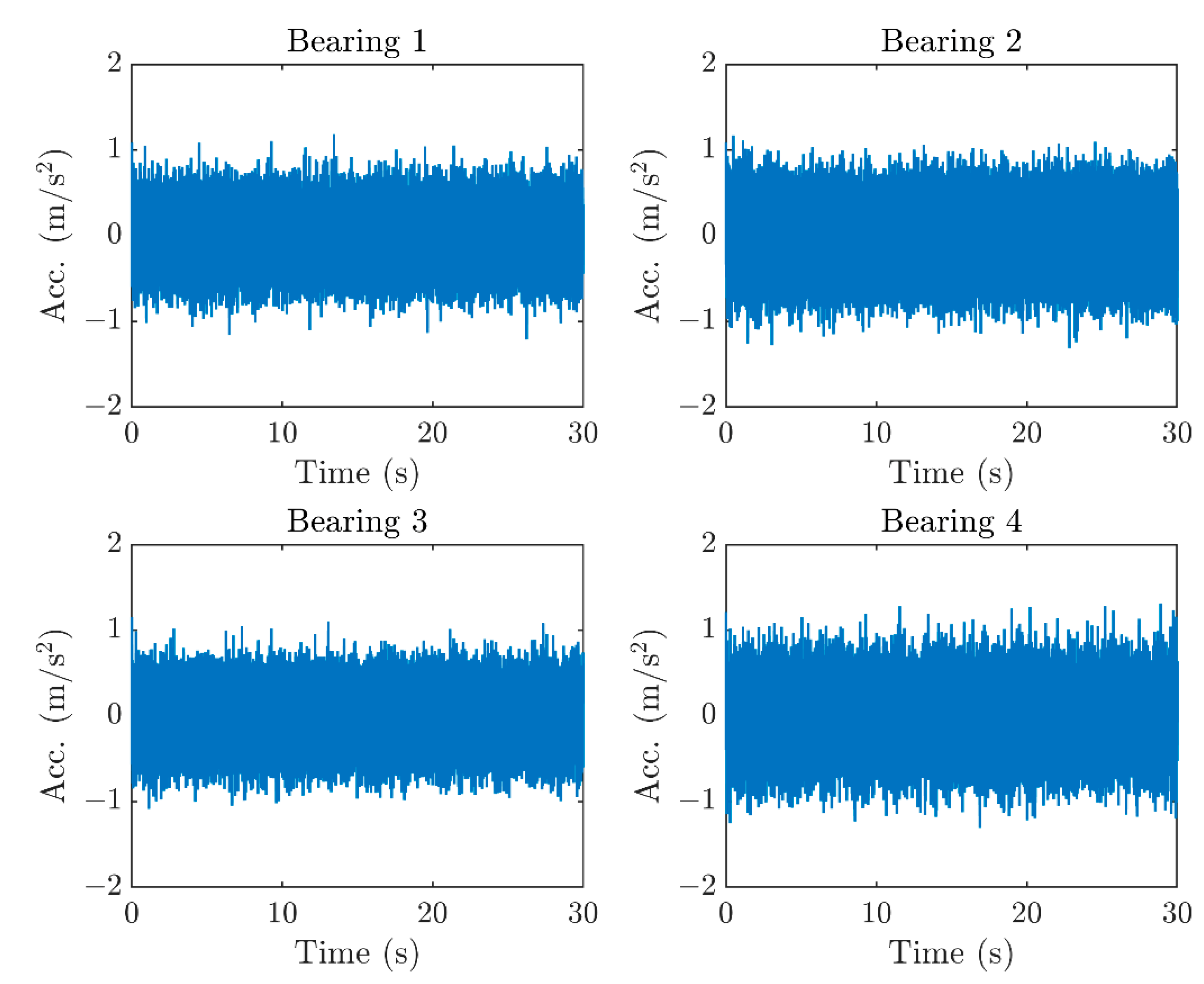
Figure 11 shows the four signals acquired for the nominal speed of 331 rpm with 62.4 kN of radial load.
Time domain features have been analyzed first. Particularly, the peak value, Root Mean Square (RMS), Crest factor and Kurtosis have been computed for each signal to characterize the vibration signature. RMS provides information about the overall signal energy content. Crest factor, instead, is defined as the ratio between the peak value and the RMS. It provides an insight into the sharpness of the time waveform and it is sensitive to peaks, despite the poor energetic contribution [
34,
35]. Kurtosis is the normalized fourth-order statistical moment of the time domain signal. A value of 3 is expected for Gaussian distributions, whereas, lower and higher values mean that the distribution produces less and more outliers than Gaussian processes, respectively.
The experimental activity led to 160 vibration signals, which resulted from 40 acquisitions for each of the 4 bearings. The 160 samples have been grouped by source bearing (4 groups of 40 acquistions), load case (4 groups of 40 acquistions) and nominal speed (10 groups of 16 acquisitions). For each of the time domain features, ANOVA tests [
36] showed that differences among acquistions of distinct bearings could be considered statistically significant, with the widest confidence intervals. Indeed, the smallest
p-values (
Table 3) resulted from grouping data with respect to source bearing, rather than relatively to load or nominal speed. The
p-values emphasized that differences exsisting between signals of diverse bearings are not casual, with a high confidence level. Therefore, it can be inferred that at least one bearing imprints the time domain features in a significantly different manner. The differences established among signals at distinct loads or speeds are otherwise significant for all the features, but with narrower confidence intervals (0.05 significance level).
Therefore, the mean,
, and the standard deviation,
, of the time domain features have been computed to characterize each of the four bearings (
Table 4). Crest factors reveal the presence of peaks in time domain signals. However, the effect of digital pre-filtering on time domain features must be further investigated. Next, the Kurtosis of the analyzed normal data is not remarkably far from Gaussian expectations, since potential impulsive phenomena are typically buried in specific frequency bands [
37]. Remarkably, bearing 2 showed a more consistent energy content, which motivates a lower crest factor. This effect suggests that the waveform characterizing bearing 2 is slightly smoother.
The frequency analysis has been based on the well-known Fast Fourier Transform algorithm (FFT). Vibration spectra show that most of the harmonic content is enclosed in lower frequencies (
Figure 10). The torque harmonics play a relevant role. Induction Motor Harmonics (IMH) stem from the three-phase current and from the rotating magnetic field, typical of induction machines. In these frameworks, the fluctuating part of the supplied torque only includes the Induction Motor Harmonics,
[
38,
39], where
is the rotational frequency of the magnetic field. The synchronous speed,
, is given by
. The
is further related to the current frequency,
, by the relation
, where
is the number of pair poles. In the performed tests,
corresponds to the nominal speed and the motor holds two pair poles.
Figure 12 shows the frequency spectrum of the bearing 2 for the nominal speed of 331 rpm with 62.4 kN of radial load. IMH are straightforwardly identifiable in the vibration spectrum and the first IMH explains most of the frequency content peculiar for the healthy machine. However, some contributions at the frequencies of 50, 100 and 150 Hz were flattened by the signal pre-filtering introduced in order to reduce electrical noise. Green circles, instead, point out the harmonics of the
.
For completeness, the bearing characteristic frequencies for the tested bearings SKF 22,240 CCK/W33 are also summarized in
Table 5 for the generic actual shaft rotational frequency,
. These frequencies and their harmonics were, however, not directly recognizable in the vibration signals of the healthy bearings under test.
As the IMH are linked to rotor excitation sources, they are expected to slide on frequency spectra according to the spin speed. This is shown in
Figure 13, which presents a comparison between frequency spectra at the nominal speeds of 331 and 211 rpm for 62.4 kN. Since the speeds have no common denominators, the
harmonics are all different and, in principle, they excite distinct stator characteristic frequencies. Therefore, the peaks associated to the red dotted lines in
Figure 13 can be unambiguously paired with rotor-related harmonics, which are exactly the IMH due to torque pulsations.
The frequency analysis highlighted that, for the investigated working conditions, the electric torque pulsations dominate the signals’ harmonic content. Of course, less trackable contributions add to the time waveform. A deeper investigation of these effects will uncover the marks of other components by means of suitable techniques for signal enhancement.
8. Conclusions
Active monitoring processes in industrial plants can bring about benefits in the continuity of system operation, and allow avoiding unscheduled down-time. They reduce maintenance costs and improve the performance of industry machinery. A real-time monitoring system can also increase the overall safety, as it warns operators against the risk of catastrophic events and the occurrence of adverse agents, such as fire, corrosion and noise. Particularly, the real-time monitoring of bearings is fundamental for this objective, as they represent one of the essential components in industrial machinery. Highly damaged bearings are easily spotted, but this usually happens when they are close to failing. The capability of detecting defects, as soon as possible, and of acquiring data to develop some damage prediction allows, instead, to implement early corrective actions, minimizing the costs resulting from unexpected failures.
In this paper, the design of a new test rig for the characterization of industrial bearings and the development of a smart bearing concept were investigated. The first task dealt with a lack of assessed facilities covering some specific and daily needs of the industry, such as testing large-sized bearings, undergoing huge loads and measuring some actions, such as the friction torque, extremely useful for designing the power units. The presented test rig will also be employed in further experimental campaigns, which will involve damaged bearing components for the development of innovative monitoring techniques.
The novel bearing test rig aims to test four middle-sized bearings simultaneously (up to 420 mm of outer diameter with current configuration) under working conditions, in terms of size, speed and loads, as close as possible to those of real industrial applications. The innovative self-balancing layout denoted as “self-contained box” allows the application of heavy loads onto the bearings under testing, avoiding a severe transmission of actions to the statoric platform. Both the activities of “in-monitoring” (bearing health) and “out-monitoring” (machine condition) can be performed using this test rig. Vibration and temperature are independently monitored for each bearing, while the friction torque opposed by bearing to shaft rotation is measured though a single-load cell that evaluates the box rotation.
A preliminary experimental characterization of this system demonstrated that some main claims of this new configuration are consistent with the real behavior of the test rig. Friction torque is measurable and is compatible with the numerical prediction of some known analytical models. System operations fulfil all the requirements defined. It works in the subcritical regime, thus avoiding any possibility of dynamic instability. Subsystems, including sensors, actuators and the motor, regularly work, despite the peculiarity of this new layout.
Nevertheless, a more complete experimental campaign will provide a detailed characterization of the whole system to create a set of reference data to define the healthy profile of this system to then be exploited in training of algorithms for an automatic detection of damages and failures in service. This activity will be carried out to characterize some typical defects of the rotor-bearing system and related failures, and to set up some innovative technologies for prognosis and diagnosis based on the machine and deep learning. Although prognostic tests are expected to be carried out, further investigations on system durability also need to be carried out, in order to fulfil the requirements of such tests.
The system modularity will help in the vibration assessment of the test rig in non-nominal working conditions, and to investigate the role of the number of defected bearings (up to four), location and number of defects (outer ring, inner ring, rolling elements) and different working loads (radially and axially, independently).


 ,
, 


