Article

Elastic Obstacle-Surmounting Pipeline-Climbing Robot with Composite Wheels

1
School of Mechanical Engineering, Southeast University, Nanjing 211189, China
2
Special Equipment Safety Supervision Inspection Institute of Jiangsu Province, Nanjing 210002, China
*
Author to whom correspondence should be addressed.
Machines 2022, 10(10), 874; https://doi.org/10.3390/machines10100874
Submission received: 16 August 2022 / Revised: 13 September 2022 / Accepted: 25 September 2022 / Published: 28 September 2022
(This article belongs to the Special Issue Intelligent Mechatronics: Perception, Optimization, and Control)

Abstract

:
Regular inspection and maintenance can ensure safe working conditions of transport pipelines without leakage and damage. Pipeline-climbing robots can be used for rapid inspection of pipelines, effectively reducing labor costs and time consumption. For the annular pipelines outside spherical tanks, the special distribution and installation form presents more high obstacles, and puts forward higher requirements for the robot’s climbing performance and obstacle-surmounting ability. An elastic obstacle-surmounting pipeline-climbing robot with composite wheels is proposed in this paper. The designed elastic shock-absorbing suspension mechanisms and composite wheels were designed to increase the stability and obstacle-surmounting ability of the robot. The adjustable robot frame and rotating joint mechanisms allowed the robot to adapt to pipelines of different diameters and radians. Force analysis and simulation of obstacle surmounting by the robot were performed. Experiments were conducted on a 110-mm diameter pipeline to test the payload performance and obstacle-surmounting ability of the robot. With its elastic shock-absorbing suspension mechanisms, the pipeline-climbing robot could carry a 30 kg payload and stably climb the pipeline. The maximum height of obstacles surmounted by the composite wheels of the robot was 20 mm. In the process of surmounting obstacles, the velocity and inclination angle of the robot could remain relatively stable. This novel composite wheels and mechanisms can improve the performance of the pipeline-climbing robot and solve the problem of surmounting high obstacles. By carrying various equipment and instruments, the robot can promote the automated maintenance and inspection of complex pipelines.

1. Introduction

Industrial transport pipelines have been widely used worldwide due to their wide adaptability and economy. Most of the stored substances in the pipelines are flammable, explosive, and toxic, especially in petroleum and chemical storage and transportation. During long-term service, leakage, corrosion, and rust may occur in these pipelines. To ensure safe operation, pipelines require regular inspection and maintenance. Due to the complex distribution and long distances of pipelines, the manual inspection is time-consuming, dangerous, and highly difficult. Therefore, high-performance pipeline-climbing robots are urgently needed, which can carry instruments and equipment to quickly inspect pipelines.
Climbing robots have been studied and applied in various working conditions [1,2,3]. A climbing robot was able to move freely on a steel surface, carry sensors, collect data and then send data to the ground station in real-time for monitoring as well as further processing [4]. A wheel-based pole-climbing robot was composed of a triangular body with six brackets and wheels at the tips [5]. It was used primarily to climb and clean light poles. A Cartesian legged tracked-wheel crawler robot was developed for mooring chain inspection [6].
A variety of climbing robots have been used instead of manual operations, greatly improving work efficiency; these have included a lightweight pruning robot [7], a pylon maintenance robot [8], an oil tank inspection robot [9], and a climbing and pole line hardware installation robot [10]. For stable climbing, various forms of adsorption methods have been developed. For example, a reconfigurable soft wall-climbing robot actuated by electromagnet [11], a wall-climbing robot with multiple attachment modes [12], a wall-climbing robot with active sealing for radiation safety of nuclear power plants [13], a climbing robot integrating an articulated arm [14], and the Treebot, with two grippers and a continuum body for tree-climbing [15].
There has also been significant research on pipeline-climbing robots. A one-piece 3D-printed pipe-climbing robot was developed [16], composed of sequenced novel soft bending mechanisms. The robot used the small strains of soft materials to achieve large bending deformation. The robot could be adaptable to pipes with various diameters, radii of curvature, and inclinations. A pipe-climbing robot was proposed to inspect the reactor spray-piping system [17]. It had a five-DOF manipulator and two grippers and moved along cylindrical pipes like an inchworm, bypassing obstacles such as flanges and valves. A climbing robot was developed to help people inspect lamps of high-mast lighting [18]. It was driven by link chains and sprockets, which were arranged opposite to each other, to form a dual caterpillar mechanism. The compression mechanism squeezed the caterpillar, and rubber feet grasped the steel rope to generate enough adhesion forces. The suspension mechanism was used to compensate for the contraction or extension of the chains. For the climbing rod object with large diameter variation and the need for obstacle crossing, an embracing-type climbing robot was proposed [19]. The designed climbing robot could be used for climbing the rod with variations in diameter, especially the lightning rod in the transformer substation.
In addition, some robots can climb inside pipelines for inspection [20,21,22]. However, climbing robots are more convenient for communication and operation when outside pipelines [23,24]. Obstacles may appear on the outside of the pipelines, which places higher performance requirements on climbing robots. The diameter and radian of pipelines are diverse, so it is essential that pipeline-climbing robots be adjustable and adaptable.
Up to now, we have proposed a variety of climbing robots with simple structures, light weights, strong load-carrying capacity, and stable operation for high-altitude operations. A trilateral-wheeled climbing robot was developed in early studies [25], which was surrounded by three trolleys. In order to improve the installation convenience and operational dexterity, an innovative wheel-based cable inspection robot was proposed [26,27]. However, the pipelines on the outside of spherical tanks are annular and there are many high obstacles at the welding position of the pipelines, so climbing robots often cannot surmount the obstacles smoothly and maintain continuous stability.
This paper introduces an application-oriented pipeline-climbing robot with simple structure, heavy load, and strong obstacle-surmounting ability. Elastic shock-absorbing suspension mechanisms and composite wheels can improve the stability and obstacle-surmounting ability of the robot. Force analysis and simulation were performed to calculate the driving force and feasibility of the robot. Payload experiments and obstacle-surmounting experiments were conducted to test robot performance. The paper is organized as follows. In Section 2, the requirements for the robot are analyzed and the mechanism design of the pipeline-climbing robot is presented. In Section 3, modalities and forces of the obstacles to be surmounted are analyzed. In Section 4, the dynamic simulation of obstacle-surmounting process is performed. Experiments of climbing and obstacle-surmounting are presented in Section 5. Finally, conclusions and future work are discussed in Section 6.

2. Mechanism Design and Implementation

2.1. Problem Description

Pipeline equipment and devices are widely used in petrochemical, electric power, and other industrial fields. After a long period of service, pipelines may generate some safety problems, such as rust, corrosion, leakage, etc. Due to the long installation distance and complex distribution of pipelines, manual inspection is time-consuming and labor-intensive. Using pipeline-climbing robots can improve inspection efficiency and reduce safety risks. However, some pipelines are distributed at high altitudes, which makes inspection and maintenance more difficult. As shown in Figure 1, various types of pipelines are distributed on the outside and bottom of spherical tanks in the petrochemical industry. These pipelines on the outside of spherical tanks are annular with different curvatures, and are welded to the spherical tanks by L-shaped holder, which puts forward higher requirements for pipeline-climbing robots. The robot needs to climb along these pipelines and overcome the obstacles on the route.
In the mechanism design of the pipeline-climbing robot, the following requirements need to be met:
  • Adaptability of curved pipelines: the robot should be able to flexibly climb on pipelines with different curvatures and diameters.
  • Obstacle-surmounting capacity: the robot needs to avoid and surmount obstacles of different forms, such as welded L-shaped holder and uneven obstacles on pipelines.

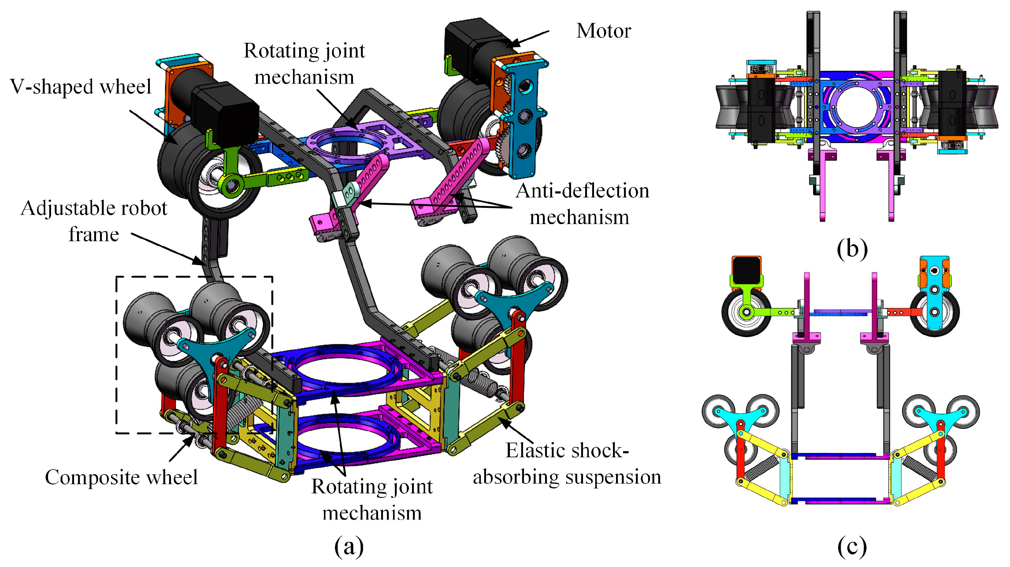
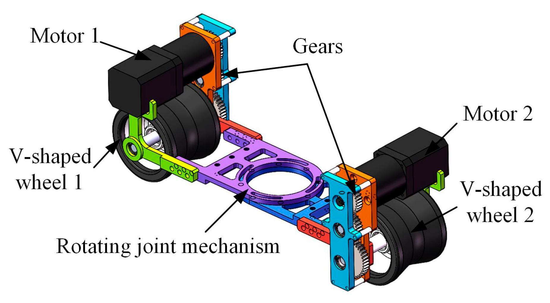
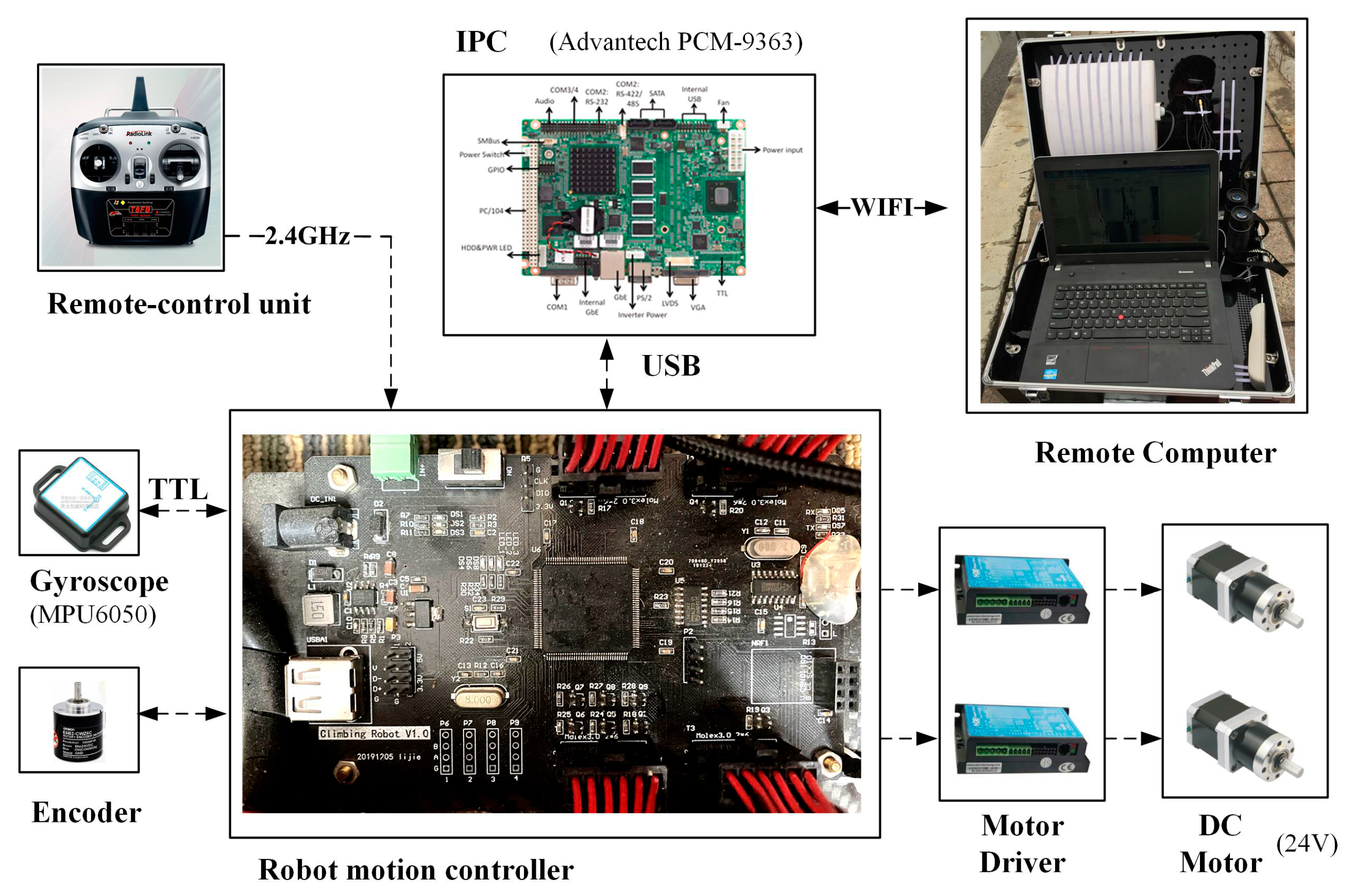
2.2. Robot Mechanical Design

Given the requirements for pipeline inspection, we propose an elastic obstacle-surmounting pipeline-climbing robot with composite wheels, which has excellent adaptability and obstacle-surmounting performance. As shown in Figure 2, the designed pipeline-climbing robot includes two V-shaped wheels, two composite wheels, two drive motors, two elastic shock-absorbing suspension mechanisms, an adjustable robot frame, and two anti-deflection mechanisms. The pipeline-climbing robot has a double-sided wheel layout, the upper V-shaped wheels are the driving wheels, and the lower composite wheels are the passive wheels.
Based on double-sided V-shaped wheels and composite wheels, the robot can be clamped on pipelines. The V-shaped wheels have a 150° scalloped surface, which is conducive to full contact with the pipelines. The adjustable robot frame can change the distance between the V-shaped wheels and composite wheels to accommodate different diameter pipelines. Three rotating joint mechanisms are arranged in the middle of the robot, and the robot can adapt to the curvature of pipelines through rotation adjustment. The barycenter of the robot is low, which can prevent overturning when climbing.
Anti-deflection mechanisms are used to prevent the robot from leaving the pipeline and ensure safe operation. Small wheels are installed at the bottom of the anti-deflection mechanisms. In the normal climbing state, there is a small gap between the anti-deflection wheels and the pipeline; when the robot deviates from the pipeline, the anti-deflection wheels contact the pipeline and guide the robot to return to the normal route.
Figure 3 shows driving mechanisms of the robot, which provide power for climbing. Two motors are located above the V-shaped wheels and transmit power through multiple gears. The symmetrical layout makes the mass load of the motors evenly distributed on two V-shaped wheels to avoid the sideways shaking of the robot. These two groups of driving mechanisms can rotate flexibly through the rotating joint mechanism.
Figure 4 shows the elastic shock-absorbing suspension mechanisms and composite wheels. The composite wheel consists of three small V-shaped wheels, which can rotate flexibly along its own axis. The elastic shock-absorbing suspension mechanism is a four-bar linkage. The composite wheel position can be adjusted by changing the shape and position of the connecting links. The diagonal joints of the four-bar linkage are tensioned by springs to provide pressing force for the composite wheels. Similarly, two elastic shock-absorbing suspension mechanisms can rotate flexibly through two rotating joint mechanisms.
Figure 5 shows the schematic diagram of the robot climbing on curved pipelines of spherical tanks. In order to adapt to curved pipelines, the robot can change the angle between the front and rear wheels through rotating joint mechanisms. The parameters of the pipeline-climbing robot are shown in Table 1. The outer diameter of the V-shaped wheels is 78 mm, and the diameter of the small V-shaped wheels in the composite wheels is 52 mm. With the adjustable robot frame, the robot can climb the pipeline with a maximum diameter of 250 mm. The maximum climbing speed of the robot is 0.35 m/s. The dual-motor drive improves the motion performance of the robot, and the elastic shock-absorbing suspensions and composite wheels enhance the robot’s obstacle-surmounting capacity. Compared with our previous climbing robot [28], the maximum climbing speed is increased from 0.22 m/s to 0.3 m/s, and the maximum height of surmounted obstacle is enhanced from 13 mm to 20 mm. In addition, this robot is more flexible and can adapt to curved pipes.

3. Analysis of Obstacle Surmounting

3.1. Obstacle-Surmounting Modality

For obstacles of different heights, the robot has different obstacle-surmounting modalities. Compared with ordinary V-shaped wheels, the composite wheels can surmount higher obstacles. Figure 6 shows the obstacle-surmounting process of the pipeline-climbing robot. Depending on the height of the obstacle, there are two possibilities in obstacle-surmounting modality:
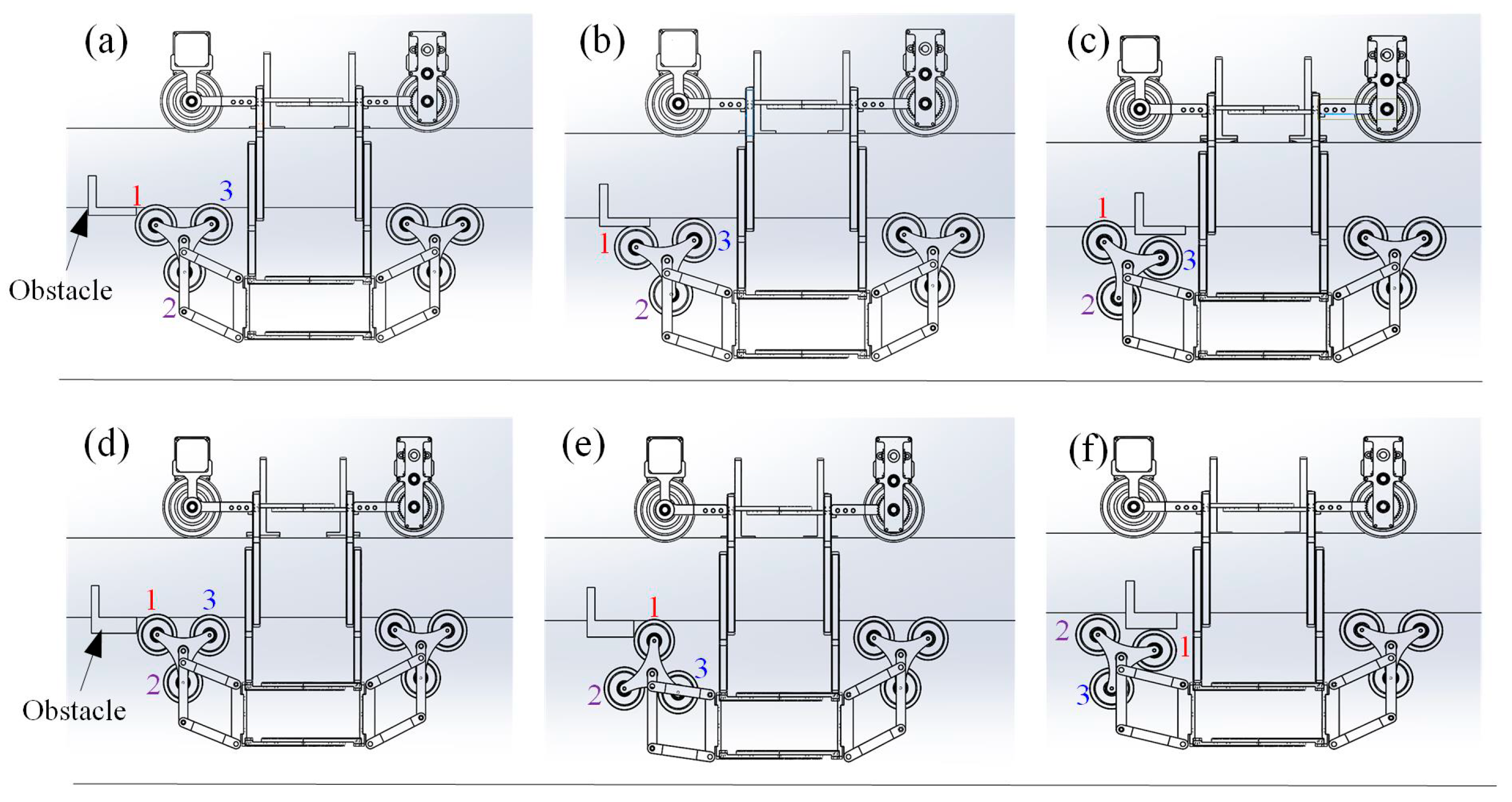
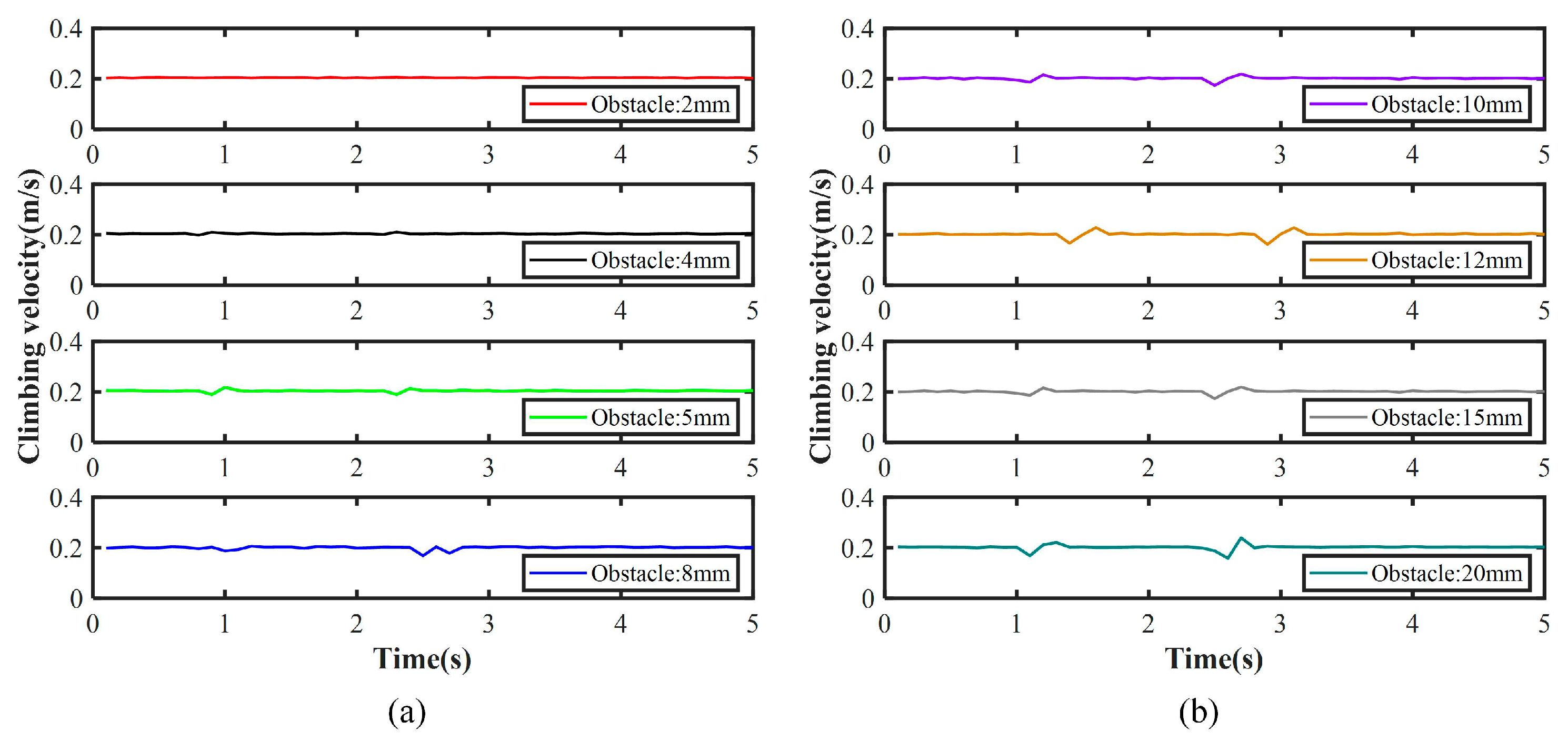
  • When the obstacle height is low (such as 3 mm), the composite wheels will be lifted to surmount the obstacle directly. The small V-shaped wheels of the composite wheels alternately pass the obstacle and return to the initial state.
  • When the obstacle height is high (such as 20 mm), the small V-shaped wheels of the composite wheels will be blocked, and the composite wheels will surmount the obstacle by rotating modality. In this process, one small V-shaped wheel changes from the contact state to the suspended state, and the other suspended small V-shaped wheel contacts and surmounts the obstacle. Three small V-shaped wheels of the composite wheel can surmount higher obstacles by rotating themselves.

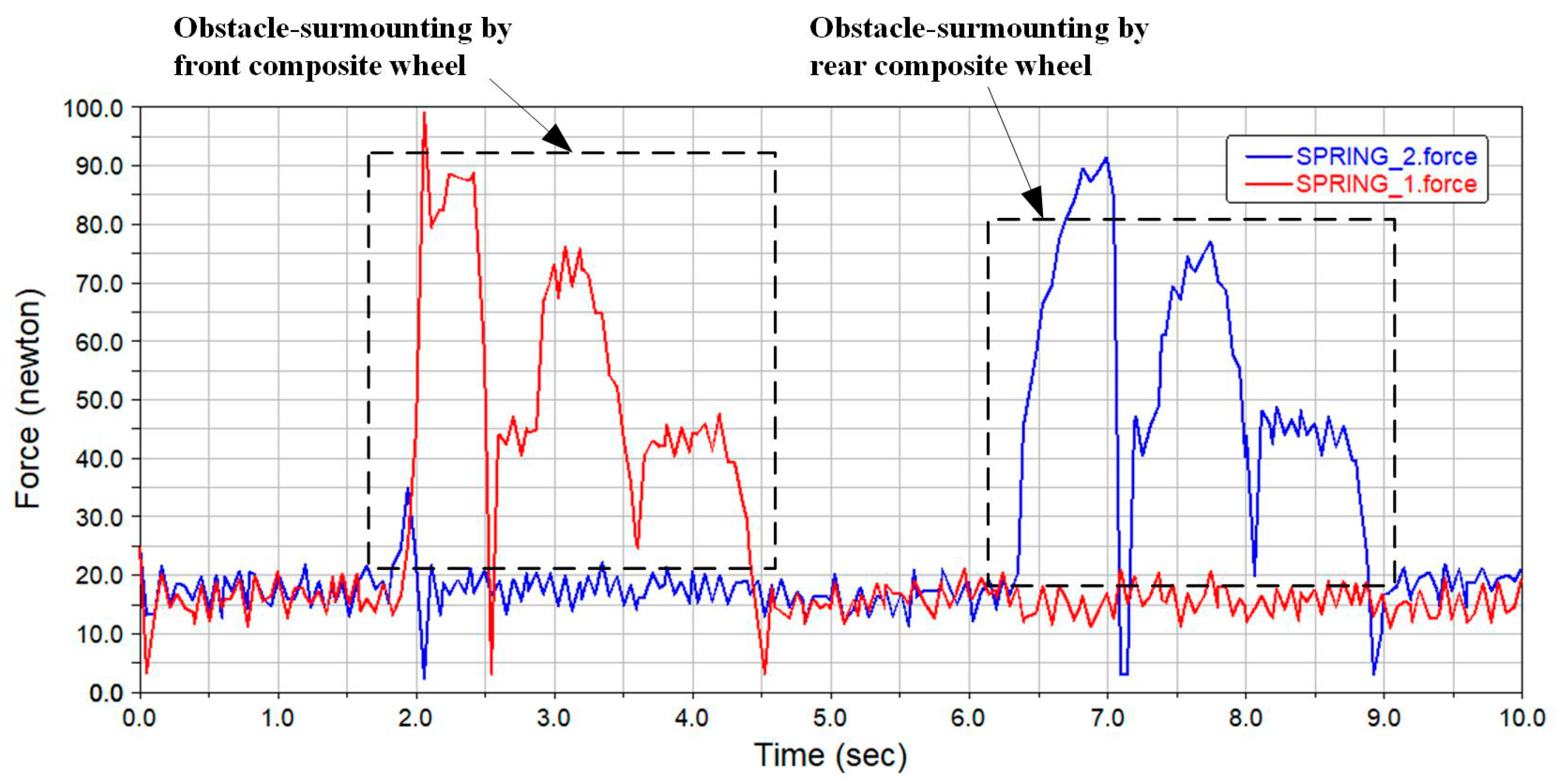
3.2. Force Analysis of ObstacleSurmounting

The elastic shock-absorbing suspension mechanisms of the pipeline-climbing robot are equipped with tension springs, which are used to provide applicable pressing forces between the passive wheels (composite wheels) and the driving wheels (V-shaped wheels), so that the robot can be clamped on pipelines. The pipeline-climbing robot needs to pass obstacles when climbing along pipelines. When the robot surmounts obstacles, the passive wheels are lifted, the elastic shock-absorbing suspension mechanisms change shape, the springs are elongated, and the tension forces change accordingly.
During the obstacle-surmounting process, the tension forces of the springs change dynamically. If the tension forces provided by the springs are too small, the pipeline cannot be tightened, and the robot may slip or roll over; on the contrary, if the tension forces are too large, the robot may fail to surmount the obstacle due to its inability to overcome the excessive positive pressure. Therefore, it is necessary to analyze the robot dynamics in the obstacle-surmounting process, and determine the appropriate preload and elastic coefficient of the springs.
When the robot surmounts high obstacles, the deformation of the elastic shock-absorbing suspension mechanisms is large, the tension forces of the springs change greatly, and the robot is subjected to complex forces. The forces and dynamics of the robot surmounting high obstacles are analyzed. When the robot climbs on a pipeline with a radius of R p , the force analysis of obstacle-surmounting is shown in Figure 7. The robot moves to the left along the horizontal pipeline, its displacement is x , and the height of the obstacle is Δ h . Point A is the gyration center of the front composite wheel, Point B is the center of the first small V-shaped wheel, and Points C, D, and E are the rotation points of the elastic suspension mechanism. The symbols and parameter definitions in the force analysis are shown in Table 2.
During the process of surmounting the obstacle, the front composite wheel touches the obstacle first, and the rear does not. Figure 8 shows the force analysis and suspension deformation of two composite wheels. Since the small V-shaped wheels can rotate freely through bearings, the influence of the rolling friction force ( F f p 1 , F f p 2 and F f p 3 ) of the composite wheels on the robot velocity is ignored. In this process, the front composite wheel tends to rotate due to the obstacle, its first small V-shaped wheel is stuck, and the other small V-shaped wheel is gradually lifted, so only the first small V-shaped wheel is subject to positive pressure and friction force.
For the rear composite wheel, the static friction force can cause the small V-shaped wheels to rotate without affecting the robot’s motion. We can obtain:
F f p 2 r p w = J p w x ¨ r p w
The coordinate system XOY is established, and the center of the robot is the origin. According to the force balance of the robot, the following can be obtained:
{ F x + F f d 1 + F f d 2 = G t x ¨ g F y + F N p 1 + F N p 2 + F N p 3 + G t = F N d 1 + F N d 2
During the obstacle-surmounting process, the front composite wheel rotates. Due to small rotational velocity and angle, the moment of inertia of the front composite wheel is ignored. According to the force balance analysis of the two composite wheels in the Y coordinate axis direction, we can derive the following:
{ F y + F N p 1 + G p w F N k 1 = G p w l p φ ¨ p cos φ p g F N p 2 + F N p 3 + G p w F N k 2 = 0
According to the geometric relationship of the four-bar linkage, two positive pressures provided by the elastic suspensions are:
{ F N k 1 = k c 1 ( c 1 c 0 ) a F N k 2 = k c 2 ( c 2 c 0 ) a
The spring length c 1 and c 2 of two elastic suspensions can be expressed as:
{ c 1 = a 2 + b 2 2 a b ( h p l p sin φ p ) c 2 = a 2 + b 2 2 a b ( h p l p sin π 6 )
The reliability of the passive composite wheels can be directly reflected by the positive pressure from the pipeline. Assume that the resultant forces of the positive pressures acting on the front and rear composite wheels are F c 1 and F c 2 , respectively. We can obtain:
{ F c 1 = F y + F N p 1 = G p w l p φ ¨ p cos φ p g + k c 1 ( c 1 c 0 ) a G p w F c 2 = F N p 2 + F N p 3 = k c 2 ( c 2 c 0 ) a G p w
c 1 is a variable of φ p , which increases with the deformation of the elastic suspensions. The resistance force of the obstacle to the robot points to the center of the front composite wheel. In order to surmount the obstacle, the driving force F d of the robot needs to overcome the component force of the resistance force in the direction of X coordinate axis. The driving force F d meets:
F d F N k 1 cot φ p = k c 1 ( c 1 c 0 ) cot φ p a
The driving force of the robot is provided by the friction force on the V-shaped wheels, so the driving force F d should satisfy:
F d = F f d 1 + F f d 2 μ ( F N d 1 + F N d 2 )
Combining Equations (2), (3) and (8), we get:
F d = F x + G t x ¨ g = F f d 1 + F f d 2 μ ( F N d 1 + F N d 2 ) = μ ( G p w l p φ ¨ p cos φ p g + F N k 1 + F N k 2 + G t 2 G p w )
According to Equation (6), the initial positive pressures can be set by changing the length and elastic coefficient of the springs. Equations (7) and (9) describe the relationship between the tension force of the springs and the driving force of the robot. By selecting the acceleration value of the robot, the maximum tension force of the springs can be calculated, and then the driving force and torque of the motors can be obtained.

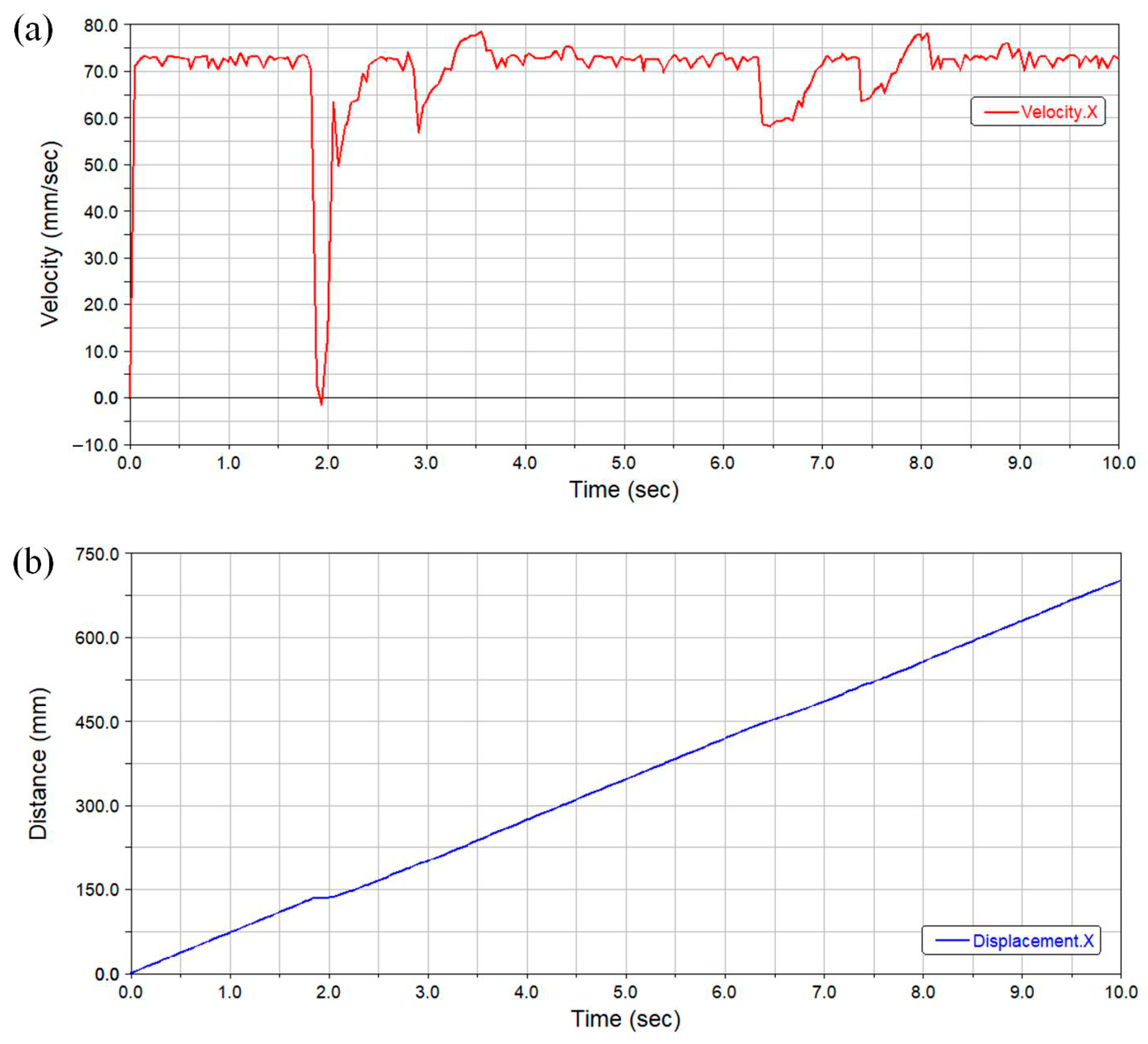
4. Virtual Model Simulation Analysis

In order to simulate the motion performance and obstacle-surmounting ability of the designed robot, under the conditions of given constraints and external forces, a virtual model simulation analysis was performed by establishing the kinematic and dynamic model of this complex robotic system. It is a complex dynamic process involving collision, deformation, and friction for the pipeline-climbing robot to surmount high obstacles. The climbing state and obstacle-surmounting process of the robot on a pipeline were simulated by Automatic Dynamic Analysis of Mechanical Systems (ADAMS). The simulation results are used to verify the performance and feasibility of the robot mechanical mechanism.
Based on the force analysis of obstacle surmounting, the value range of the spring tension can be calculated by setting the expected velocity and acceleration of the robot. The spring force is in a state of constant change during the obstacle crossing process. In the process of surmounting the obstacle, the tension forces of the springs are constantly changing, which is a complex nonlinear variation. During the simulation process, the initial length and elastic coefficient of the springs were continuously adjusted until the robot could climb and surmount obstacles. Robot velocity, displacement, and tension force of the robot were recorded and analyzed.
The simulation model of the robot is shown in Figure 9. Since the robot is composed of many mechanical parts, a large number of constraints were added. In the initial stage, taking into account the payload carried by the robot (such as batteries and drives), an additional mass of 5 kg was added to the lower part of the robot. The initial tension force of the springs was given as 20 N, the motor speed was given as 15 rpm, and obstacle height was 20 mm. The simulation process of the robot surmounting the obstacle is shown in Figure 10.
Robot velocity and displacement curves during the obstacle-surmounting process are shown in Figure 11. From 1.8 s to 4.6 s, the front composite wheel surmounts the obstacle; from 6.3 s to 8.9 s, the rear composite wheel surmounts obstacle. When the front composite wheel encounters the obstacle at 1.8 s, its small V-shaped wheels are stuck, and the robot velocity drops rapidly from 72.5 mm/s; then the front composite wheel rotates to surmount the obstacle, and the robot velocity is about 50 mm/s; finally, the robot velocity returns to the initial value after completely surmounting the obstacle. At 6.3 s, the rear composite wheel begins to surmount the obstacle, and robot velocity is more stable than before. During the entire obstacle-surmounting process, the forward displacement of the robot fluctuates slightly.
Figure 12 shows the change curves of spring tension forces during the obstacle-surmounting process of the composite wheels. The initial given spring tension forces are 20 N, and after the robot clamps the pipeline, the spring tension forces are about 17 N. The tension force changes of the front and rear composite wheels surmount the obstacle are similar. When the robot encounters the obstacle, the composite wheels rotate, the elastic suspension mechanisms deform, and the spring tension forces reach the maximum value when the deformation are the largest. At 2 s and 6.5 s, the maximum values of the spring tension forces are 100 N and 92 N, respectively.
The simulation results of robot obstacle-surmounting indicated that the most difficult moment is when the wheels touch the obstacle. Under the given constant motor speed, the V-shaped wheels did not slip during the period of climbing and obstacle-surmounting. The simulation results verified the feasibility of the mechanism design of the robot and obstacle-surmounting capability.

5. Experiments

Figure 13 shows the composition of the robot control system. The hardware of the robot control system includes: a robot motion controller, an industrial personal computer (IPC), two motor drivers, two DC brushless motors, a gyroscope, an encoder, a remote control unit, and a remote computer. The robot is powered by a lithium battery (24V10AH). The robot motion controller is developed to control the speed of the robot, record motion state, and process sensor data. The speed of the two are adjusted by two motor drivers, the encoder is used to collect the running speed of the robot, and the robot’s attitude is recorded by the gyroscope. The IPC is connected to the robot motion controller, and communicates with the remote computer through the wireless network. The functions of the remote computer include: robot motion control, detection monitoring, and data storage. The remote control unit is also used to control the motion status and speed of the robot.
Some experiments were performed to verify the stability and obstacle-surmounting capability of the robot, including payload experiments and obstacle-surmounting experiments. The experimental pipeline is shown in Figure 14. The diameter of the pipeline was 110 mm, and there was no obvious deflection change with 50 kg payload. Some obstacles with different heights were installed below the pipeline. Based on the analysis and simulation results, the springs of the elastic shock-absorbing suspension mechanisms were selected and installed to ensure that the robot was stably tightened on the pipeline. The spring wire diameter was 1.0mm, the length was 70 mm, and the elasticity coefficient was 8 N/mm. Five springs were simultaneously mounted on the elastic shock-absorbing suspension mechanisms.

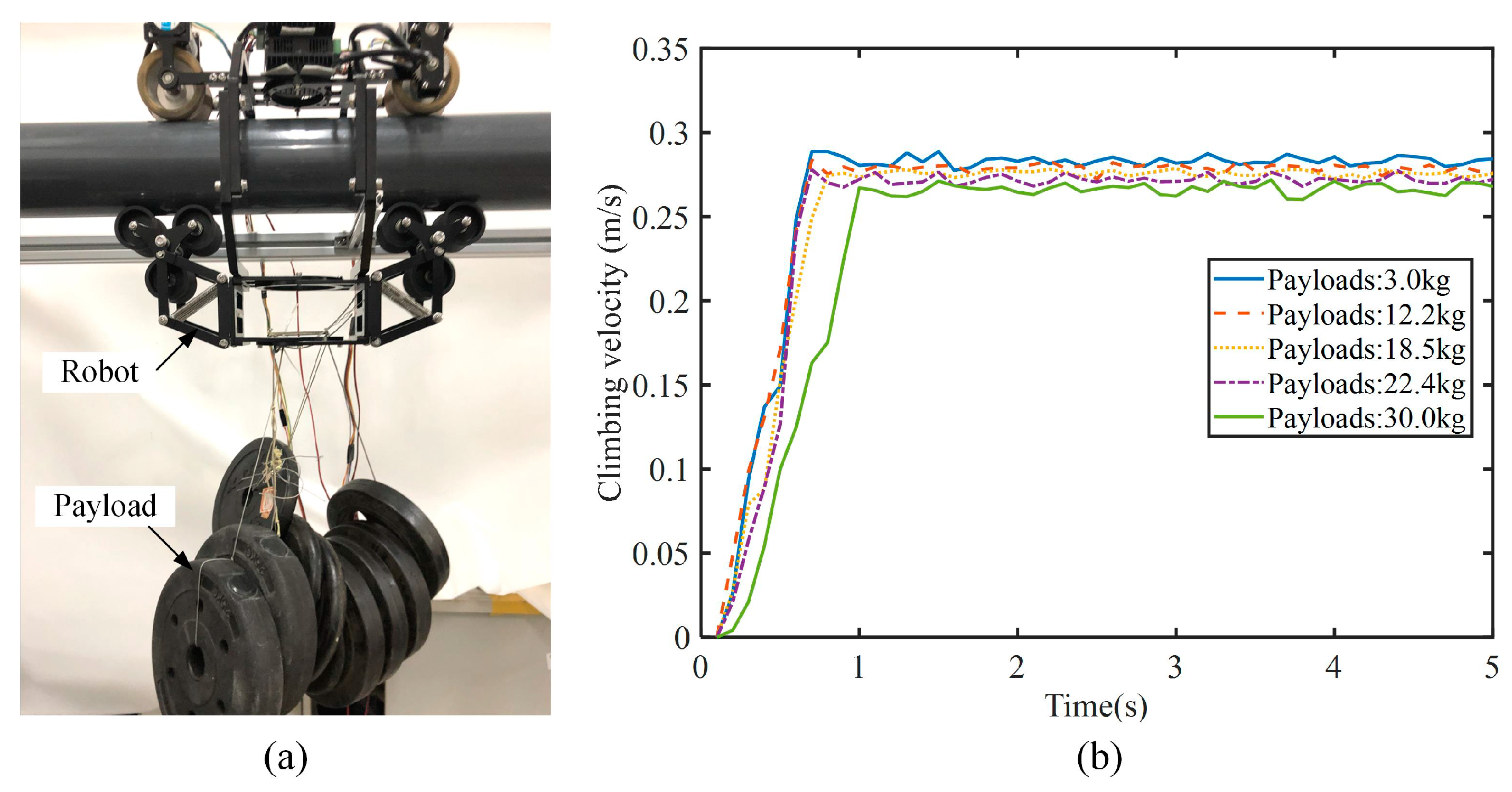
5.1. Payload Experiments

The payload experiments of the pipeline-climbing robot are shown in Figure 15. Different payloads (from 3 kg to 30 kg) were mounted on the robot frame. The robot could always clamp the pipeline stably without sideways shaking. As shown in Figure 15b, the given velocity of the robot was 0.27 m/s. When the payloads were less than 20 kg, the climbing velocity of the robot had almost no attenuation. As the payload continued to increase, the robot climbing velocity decreased. The experimental results indicated that the robot could climb stably on the pipeline with a maximum payload of 30 kg.

5.2. Obstacle-Surmounting Experiments

Obstacle-surmounting experiments were conducted to test the obstacle-surmounting ability and stability of the designed pipeline-climbing robot. The robot was clamped on the pipeline, and the climbing velocity was given as 0.2 m/s. Different obstacle heights, from 2 mm to 20 mm, were tested and evaluated. Figure 16 shows the process of the pipeline-climbing robot surmounting the obstacle with a height of 20 mm. In the experiment, when the front composite wheel touched the obstacle, the robot had a slight impact and stagnation; after passing the obstacle, the robot quickly returned to its initial state. Similarly, the rear composite wheel could also surmount the obstacle smoothly.
The velocity change curves of the robot during obstacle surmounting are shown in Figure 17. During the obstacle-surmounting process, the robot velocity has two fluctuations, which are caused by the obstacle-surmounting of the front and rear composite wheels. When the obstacle is lower than 4 mm, the robot velocity hardly fluctuates. As the height of the obstacle increases (5 mm and 8 mm), the robot velocity fluctuates slightly. When the obstacle is larger than 10 mm, the fluctuation of robot velocity is obvious, but the robot can still successfully surmount the obstacle. When surmounting these high obstacles, the composite wheels pass the obstacles by rotating its small V-shaped wheels, which is easier than lifting the entire wheels.
Figure 18 shows the change curves of the robot inclination angle during the obstacle-surmounting process. In the initial state, the inclination angle of the robot is 0°. The inclination angle of the robot also fluctuates twice due to the vibration caused by surmounting the obstacle. When the obstacle is lower than 8 mm, the angle fluctuation is very small, within ±1°. Higher obstacles cause greater angle fluctuations. When the robot surmounts the 20 mm-high obstacle, the maximum angle fluctuation remains within ±2°. The robot can maintain stability while surmounting obstacles.
Payload experiments and obstacle-surmounting experiments indicate that the pipeline-climbing robot with composite wheels has excellent stability and obstacle-surmounting performance. The elastic shock-absorbing suspension mechanisms enable the robot to be stably clamped on the pipeline and is beneficial to reducing vibration. The composite wheels make it easier for the robot to pass higher obstacles. By carrying various equipment and instruments, the robot can perform automatic inspection and maintenance of complex high-altitude pipelines.

6. Conclusions

In this paper, an elastic obstacle-surmounting pipeline-climbing robot with composite wheels is developed. With the adjustable robot frame and rotating joint mechanisms, the robot can stably climb on pipelines of different diameters and radians. The elastic shock-absorbing suspension mechanisms and composite wheels greatly enhance the stability and obstacle-surmounting ability of the robot. Force analysis and simulation were performed to calculate the driving force and feasibility of the robot to surmount obstacles. Payload experiments and obstacle-surmounting experiments were conducted to test robot performance. The results of the payload experiments indicated that the robot could stably climb a 110-mm diameter pipeline with a 30 kg payload. In obstacle-surmounting experiments, the robot with composite wheels could surmount the 20 mm high obstacle. In the process of surmounting obstacles, the maximum angle fluctuation remained within ±2°. This high-performance pipeline-climbing robot may contribute to improving the efficiency of complex pipeline inspection and maintenance by carrying various equipment and instruments.
In this study, there are some limitations in laboratory experiments, and the reliability and practicability of the robot prototype cannot be fully verified. In future research, more experiments under various working conditions will be performed to test the robot’s operating status, shock absorption, and inspection ability. Some field tests of the robot carrying testing tools and maintenance machinery on the pipelines of industrial spherical tanks will be carried out to improve the robot’s performance.

Author Contributions

J.L. contributed to robot mechanism design, force analysis, and manuscript preparation. F.H. and C.T. contributed to robot experiments and result analysis. X.W. and M.T. contributed to the conception and supervision of the study. All authors have read and agreed to the published version of the manuscript.

Funding

This research was funded by the National Key Research and Development Program of China (SQ2021YFF05002684).

Institutional Review Board Statement

Not applicable.

Informed Consent Statement

Not applicable.

Data Availability Statement

All data included in this study are available upon request by contact with the corresponding author.

Conflicts of Interest

The authors declare no conflict of interest.

References

  1. Nguyen, S.T.; La, H.M. A Climbing Robot for Steel Bridge Inspection. J. Intell. Robot. Syst. Theory Appl. 2021, 102, 1–21. [Google Scholar] [CrossRef]
  2. Liu, J.; Xu, L.; Xu, J.; Liu, L.; Cheng, G.; Chen, S.; Xu, H.; Shi, J.; Liang, X. Analysis and Optimization of the Wall-Climbing Robot with an Adsorption System and Adhesive Belts. Int. J. Adv. Robot. Syst. 2020, 17. [Google Scholar] [CrossRef]
  3. Lee, G.; Kim, H.; Seo, K.; Kim, J.; Kim, H.S. MultiTrack: A Multi-Linked Track Robot with Suction Adhesion for Climbing and Transition. Rob. Auton. Syst. 2015, 72, 207–216. [Google Scholar] [CrossRef]
  4. La, H.M.; Dinh, T.H.; Pham, N.H.; Ha, Q.P.; Pham, A.Q. Automated Robotic Monitoring and Inspection of Steel Structures and Bridges. Robotica 2019, 37, 947–967. [Google Scholar] [CrossRef]
  5. Noohi, E.; Mahdavi, S.S.; Baghani, A.; Ahmadabadi, M.N. Wheel-Based Climbing Robot: Modeling and Control. Adv. Robot. 2012, 24, 1313–1343. [Google Scholar] [CrossRef]
  6. Dissanayake, M.; Sattar, T.P.; Lowe, S.; Pinson, I.; Gan, T. Hean Adaptable Legged-Magnetic Adhesion Tracked Wheel Robotic Platform for Misaligned Mooring Chain Climbing and Inspection. Ind. Rob. 2018, 45, 634–646. [Google Scholar] [CrossRef]
  7. Ueki, S.; Kawasaki, H.; Ishigure, Y.; Koganemaru, K.; Mori, Y. Development and Experimental Study of a Novel Pruning Robot. Artif. Life Robot. 2011, 16, 86–89. [Google Scholar] [CrossRef]
  8. Lu, X.; Zhao, S.; Liu, X.; Wang, Y. Design and Analysis of a Climbing Robot for Pylon Maintenance. Ind. Robot Int. J. 2018, 45, 206–219. [Google Scholar] [CrossRef]
  9. Ding, Y.; Sun, Z.; Chen, Q. Non-Contacted Permanent Magnetic Absorbed Wall-Climbing Robot for Ultrasonic Weld Inspection of Spherical Tank. MATEC Web Conf. 2019, 269, 02013. [Google Scholar] [CrossRef]
  10. Allan, J.-F.; Lavoie, S.; Reiher, S.; Lambert, G. Climbing and Pole Line Hardware Installation Robot for Construction of Distribution Lines. In Proceedings of the 2010 1st International Conference on Applied Robotics for the Power Industry (CARPI 2010), Montreal, QC, Canada, 5–7 October 2010; pp. 1–5. [Google Scholar]
  11. Zhang, W.; Zhang, W.; Sun, Z. A Reconfigurable Soft Wall-Climbing Robot Actuated by Electromagnet. Int. J. Adv. Robot. Syst. 2021, 18. [Google Scholar] [CrossRef]
  12. Liu, J.; Xu, L.; Chen, S.; Xu, H.; Cheng, G.; Xu, J. Development of a Bio-Inspired Wall-Climbing Robot Composed of Spine Wheels, Adhesive Belts and Eddy Suction Cup. Robotica 2021, 39, 3–22. [Google Scholar] [CrossRef]
  13. Kim, D.; Kim, Y.S.; Noh, K.; Jang, M.; Kim, S. Wall Climbing Robot with Active Sealing for Radiation Safety of Nuclear Power Plants. Nucl. Sci. Eng. 2020, 194, 1162–1174. [Google Scholar] [CrossRef]
  14. Tavakoli, M.; Lourenço, J.; Viegas, C.; Neto, P.; de Almeida, A.T. The Hybrid OmniClimber Robot: Wheel Based Climbing, Arm Based Plane Transition, and Switchable Magnet Adhesion. Mechatronics 2016, 36, 136–146. [Google Scholar] [CrossRef]
  15. Lam, T.L.; Xu, Y. Motion Planning for Tree Climbing with Inchworm-like Robots. J. Field Robot. 2013, 30, 87–101. [Google Scholar] [CrossRef]
  16. Xie, D.; Liu, J.; Kang, R.; Zuo, S. Fully 3D-Printed Modular Pipe-Climbing Robot. IEEE Robot. Autom. Lett. 2021, 6, 462–469. [Google Scholar] [CrossRef]
  17. Kim, J.H.; Lee, J.C.; Choi, Y.R. PiROB: Vision-Based Pipe-Climbing Robot for Spray-Pipe Inspection in Nuclear Plants. Int. J. Adv. Robot. Syst. 2018, 15. [Google Scholar] [CrossRef]
  18. Li, P.; Duan, X.; Sun, G.; Li, X.; Zhou, Y.; Liu, Y. Design and Control of a Climbing Robot for Inspection of High Mast Lighting. Assem. Autom. 2019, 39, 77–85. [Google Scholar] [CrossRef]
  19. Chen, G.; Yang, H.; Cao, H.; Ji, S.; Zeng, X.; Wang, Q. Design of an Embracing-Type Climbing Robot for Variation Diameter Rod. Ind. Rob. 2019, 46, 56–72. [Google Scholar] [CrossRef]
  20. Xiao, S.; Bing, Z.; Huang, K.; Huang, Y. Snake-like Robot Climbs inside Different Pipes. In Proceedings of the 2017 IEEE International Conference on Robotics and Biomimetics, ROBIO 2017, Macau, China, 5–8 December 2017. [Google Scholar]
  21. Li, T.; Ma, S.; Li, B.; Wang, M.; Li, Z.; Wang, Y. Development of an In-Pipe Robot with Differential Screw Angles for Curved Pipes and Vertical Straight Pipes. J. Mech. Robot. 2017, 9, 1–11. [Google Scholar] [CrossRef]
  22. Xu, Z.L.; Lu, S.; Yang, J.; Feng, Y.H.; Shen, C.T. A Wheel-Type in-Pipe Robot for Grinding Weld Beads. Adv. Manuf. 2017, 5, 182–190. [Google Scholar] [CrossRef]
  23. Li, X.; Gao, C.; Guo, Y.; He, F.; Shao, Y. Cable Surface Damage Detection in Cable-Stayed Bridges Using Optical Techniques and Image Mosaicking. Opt. Laser Technol. 2019, 110, 36–43. [Google Scholar] [CrossRef]
  24. Cho, K.H.; Jin, Y.H.; Kim, H.M.; Moon, H.; Koo, J.C.; Choi, H.R. Multifunctional Robotic Crawler for Inspection of Suspension Bridge Hanger Cables: Mechanism Design and Performance Validation. IEEE/ASME Trans. Mechatron. 2017, 22, 236–246. [Google Scholar] [CrossRef]
  25. Xu, F.; Hu, J.L.; Jiang, G. The Obstacle-Negotiation Capability of Rod-Climbing Robots and the Improved Mechanism Design. J. Mech. Sci. Technol. 2015, 29, 2975–2986. [Google Scholar] [CrossRef]
  26. Xu, F.; Dai, S.; Jiang, Q.; Wang, X. Developing a Climbing Robot for Repairing Cables of Cable-Stayed Bridges. Autom. Constr. 2021, 129, 103807. [Google Scholar] [CrossRef]
  27. Xu, F.; Wang, X.; Wang, L. Cable Inspection Robot for Cable-Stayed Bridges: Design, Analysis, and Application. J. Field Robot. 2011, 28, 441–459. [Google Scholar] [CrossRef]
  28. Li, J.; Yin, C.; Shi, Y.; Dai, S.; Wang, X. Circumferentially Rotatable Inspection Robot with Elastic Suspensions for Bridge Cables. Ind. Rob. 2022, 49, 981–993. [Google Scholar] [CrossRef]
Figure 1. Circular pipelines outside spherical tanks.
Machines 10 00874 g001
Figure 2. Mechanical structure of the pipeline-climbing robot: (a) Overall view; (b) Top view; (c) Side view.
Machines 10 00874 g002
Figure 3. Driving mechanism of the pipeline-climbing robot.
Machines 10 00874 g003
Figure 4. Composite wheels and elastic shock-absorbing suspension mechanisms: (a) Overall view; (b) Side view; (c) Top view.
Machines 10 00874 g004
Figure 5. Schematic diagram of the robot climbing on curved pipelines of spherical tanks.
Machines 10 00874 g005
Figure 6. Obstacle-surmounting modality of pipeline-climbing: (ac) Surmounting low obstacle; (df) Surmounting high obstacle.
Machines 10 00874 g006
Figure 7. Force analysis of obstacle-surmounting by the pipeline-climbing robot.
Machines 10 00874 g007
Figure 8. Force and deformation analysis of composite wheels: (a) Force analysis of the front composite wheel; (b) Suspension deformation of the composite wheel; (c) Force analysis of the rear composite wheel.
Machines 10 00874 g008
Figure 9. Virtual model simulation analysis.
Machines 10 00874 g009
Figure 10. Simulation process of obstacle surmounting by the robot: (ad) Obstacle surmounting by the front composite wheel; (eh) Obstacle surmounting by the rear composite wheel.
Machines 10 00874 g010
Figure 11. The simulation results of robot velocity and displacement: (a) Robot forward velocity; (b) Robot forward displacement.
Machines 10 00874 g011
Figure 12. The simulation results of spring tension forces.
Machines 10 00874 g012
Figure 13. Control system of the pipeline-climbing robot.
Machines 10 00874 g013
Figure 14. Experiment platform and tension spring installation: (a) Experiment platform; (b) Spring installation.
Machines 10 00874 g014
Figure 15. Payload experiments of the pipeline-climbing robot: (a) Robot and Payloads; (b) Robot climbing velocities with different payloads.
Machines 10 00874 g015
Figure 16. Obstacle-surmounting experiments: (ae) Obstacle surmounting by the front composite wheel; (fi) Obstacle surmounting by the rear composite wheel.
Machines 10 00874 g016
Figure 17. Robot velocity in obstacle-surmounting experiments. (a) Obstacle height: 2–8 mm; (b) Obstacle height: 10–20 mm.
Machines 10 00874 g017
Figure 18. Robot angle in obstacle-surmounting experiments. (a) Obstacle height: 2–8 mm; (b) Obstacle height: 10–20 mm.
Machines 10 00874 g018
Table 1. Parameters of the pipeline-climbing robot.
Dimension434 × 389 × 310 mm
Outer diameter of V-shaped wheels78 mm
Outer diameter of composite wheels 52 mm
Mass8.5 kg
Payload30 kg
Motor power120 W
Maximum climbing speed0.3 m/s
Obstacle-surmounting height20 mm
Pipeline diameter50–250 mm
Table 2. Parameters in the force analysis.
SymbolMeaning
F x , F y Contact forces of the obstacle to the robot in x and y directions
F N d 1 , F N d 2 Positive pressure on the V-shaped wheels
F f d 1 , F f d 2 Static friction force on the V-shaped wheels
F N p 1 , F N p 2 , F N p 3 Positive pressure on the composite wheels
F f p 1 , F f p 2 , F f p 3 Friction force on the composite wheels
F N k 1 , F N k 2 Positive pressure provided by the elastic suspensions
G t Total robot gravity
G p w Gravity of the composite wheel
J p w Moment of inertia of the composite wheels
a , b Link length of the suspension mechanisms
c 1 , c 2 Length of the springs
c 0 Initial length of the spring
r p w Equivalent radius of the composite wheels
l p Distance from the small V-shaped wheel center
to the composite wheel center
h p Vertical distance from Point C to the pipeline wall
g Gravitational constant
k Elastic coefficient of the springs
Publisher’s Note: MDPI stays neutral with regard to jurisdictional claims in published maps and institutional affiliations.

