Article

Design and Analysis of 6-DoFs Upper Limb Assistant Rehabilitation Robot

School of Mechatronic Engineering, Changchun University of Technology, Changchun 130012, China
*
Author to whom correspondence should be addressed.
Machines 2022, 10(11), 1035; https://doi.org/10.3390/machines10111035
Submission received: 23 September 2022 / Revised: 28 October 2022 / Accepted: 3 November 2022 / Published: 7 November 2022
(This article belongs to the Section Robotics, Mechatronics and Intelligent Machines)

Abstract

:
This paper presents an assisted upper limb rehabilitation robot (ULRR) for patients who have experienced stroke who are in the middle and late stages of rehabilitation and have certain muscle strength. The ULRR can complete adduction and abduction motion of the shoulder joint (SJ) in the frontal plane in one step, which can save time and improve the efficiency of rehabilitation training. Based on the principles of ergonomics and rehabilitation medicine, the freedom degree of the upper limb and the motion range of each joint are determined, and the structure of the shoulder, the elbow, and the wrist joint of ULRR are designed. The kinematics model of the robot is established, and the kinematics equations are derived. Meanwhile, the simulation analysis and the workspace analysis of the robot are carried out, and the different movement forms of SJ adduction and abduction are compared and analyzed. Then, the trajectory of the robot is planned to complete the act of drinking water. Finally, an experimental platform is built to complete the ULRR to help participants complete the experiments of drinking water and active training. The experiments verify that the robot is suitable for rehabilitation tasks.

1. Introduction

With an aging population, the accelerated pace of life, and the influence of poor eating habits, the population of people with limb movement disorders caused by stroke is growing rapidly. Stroke is a cerebrovascular disease with high incidence, recurrence, and disability rates [1,2,3]. The survivors of the disease have different degrees of limb dysfunction. Clinical medicine shows that the most effective way to treat stroke is to do rehabilitation training after drug treatment. In traditional rehabilitation therapy, the therapist has face-to-face and long-term contact with the patient to help the patient perform repeated movement of the limbs to achieve the effect of rehabilitation therapy [4,5,6,7]. This kind of treatment relies on the therapist’s own treatment experience, and the number of therapists at this stage is quite different from the number of patients. At the same time, rehabilitation therapy has disadvantages of low efficiency and high cost and it is difficult to carry out at any time. However, the emergence of upper limb rehabilitation robots can make up for the above shortcomings, and combining robotics with medicine can make rehabilitation treatment more effective.
In the wake of developments in rehabilitation medical technology and artificial intelligence technology, rehabilitation robots for the treatment of upper limb motor dysfunction have become the focus of research. Scholars have conducted extensive research on it and made some academic achievements. A variety of rehabilitation robots are designed according to the different purposes of rehabilitation, such as ARMin robot with four active and two passive degrees of freedom (DoFs) [8], CAREX with cable driven actuator [9,10], and some upper limb rehabilitation robots with pneumatic muscle drive, unpowered, or hybrid drive [11,12,13,14,15,16,17,18]. In terms of commercialization, robots, such as Armeo Spring and Armeo Power robots, can help the patients’ limb perform multi-joint compound movements [19,20,21]. Armeo Spring is ergonomically designed with springs and an adjustment mechanism to support the entire upper extremity, while Armeo Power is designed for patients with hand and arm injuries following stroke, traumatic brain injury, or neurological disorders. Although existing upper limb rehabilitation robots can complete some upper limb movements, problems exist, such as single movement mode, insufficient degrees of freedom, and complex structures. In particular, the movement of Adduction/Abduction (A/A) in the frontal plane (FP) of the SJ cannot be completed directly. Even if some robots cover the design of this movement, there is no actuator at the joint, so the robot cannot complete the A/A movement in the FP of the SJ actively. Ergin designed a six-freedom exoskeleton robot where the SJ is driven by two actuators without A/A movement in the FP [22].
In an upper limb rehabilitation robot, when the SJ completes the A/A movement in the FP, it needs two movements to complete. First, the arm is abducted by 90 degrees in the horizontal plane (HP), and then the A/A movement is completed in the FP. EMUL is an active seven DoFs upper limb rehabilitation robot [23]. Although the SJ has three DoFs, it cannot directly complete A/A movement in the FP. It needs two movements to complete, and the whole mechanism is complex. It proposed an exoskeleton rehabilitation robot which had two active DoFs at the SJ [24]. As the initial joint in the upper limb, the SJ supports the entire arm, so being able to perform single-joint and multi-joint compound movements is essential. Meanwhile, the radial/ulnar deviation (RUD) motion of the wrist joint is neglected in some upper limb rehabilitation robots. The RiceWrist-S and MAHI EXO II wrist rehabilitation robots realized the motion of flexion/extension (F/E) of the wrist joint, ignoring the motion of RUD [25,26,27,28]. The RUD motion of the wrist joint plays an important role in the motion of the upper limb.
Therefore, in order to solve the aforementioned problems, the skeleton configuration of the upper limb is analyzed in this paper, and a six DoFs ULRR with a gravity compensation mechanism is designed. The robot adopts three driving devices in the SJ part, and it can complete the A/A in the FP of the SJ in one step. The traditional upper limb rehabilitation robot needs at least two movements to complete the movement. The first step is completed at 90 degrees abduction in the HP, and then the second step completes the A/A motion in the FP. For this reason, the training time is shortened when completing the A/A motion in the FP—that is, the number of exercises are increased within the same exercise time, and the efficiency is improved. Meanwhile, it can train the supraspinatus which is an important part of the upper body [29]. The gravity compensation device is designed in such a way that, on the one hand, it can reduce the power consumption, and on the other hand, it can protect the patient’s arm and prevent secondary injury. Furthermore, the kinematics model of the robot is derived, and the simulation analysis is completed. Finally, the quintic polynomial interpolation method is used to obtain the trajectory planning of the multi-joint compound and active movement, and a prototype is built to complete the movement which verified the rationality of the rehabilitation robot.

2. Mechanism Design

2.1. Analysis of Structure of Human Upper Limbs

Human anatomy terms describe the movement form, movement positions, and the interrelationships of human structures in anatomy. The motion of bones relative to the three principal planes of the body include horizontal, sagittal, and frontal. These planes and axis of motion are depicted in Figure 1. The body is divided into upper and lower parts by the horizontal (or transverse) plane; it is divided into left and right parts by the sagittal plane; and it is divided into front and back parts by the frontal plane which is parallel to the coronal suture of the skull.
The human body is regarded as a multi-body motion system, and joint motion is the main form of motion. The production of joint motion is mainly composed of joints, bones, muscles, and ligaments. The upper limb of the human body is mainly composed of the SJ, the upper arm, the elbow, the forearm, the wrist, and the hand. The overall structure of the upper limb is shown in Figure 2.

2.2. Analysis of Upper Limb Movement

The movement of the upper limbs of the human body has various forms, and the movement rules of the joints are relatively complex. There is not only the independent movement of a single joint, but there is also the coordinated movement of multiple joints. In this paper, the basic motion DoFs of each joint of the upper limbs is analyzed and selected as the DoFs for the designed ULRR. The schematic diagram of the basic DoFs of the upper limbs is shown in Figure 3. The glenohumeral joint (GJ) is a ball-and-socket joint. The movement of the SJ is the movement in space with the GJ as the origin, and its movement is simplified into three orthogonal movements, which are shown in Figure 3a–c. They include the F/E motion in the sagittal plane (SP) of the SJ, the A/A in the HP of the SJ, and the A/A in the FP of the SJ. Figure 3d,e show the F/E of the elbow and the RUD and the F/E of the wrist, respectively.

2.3. Configuration Design

Based on the joint configuration of the upper limbs, the upper limbs of the human body are simplified into six DoFs, namely F/E in the SP, A/A in the HP, A/A in the FP of SJ, F/E of the elbow joint, and RUD and F/E of the wrist joint. Each joint has its own limit due to anatomical limitations. Compared to the limit value of the motion range of each joint of the human’s upper limbs, the motion range of each joint of the designed upper limb rehabilitation robot are shown in Table 1.
According to the analysis of the upper limb rehabilitation mechanism and the configuration of each joint, the schematic diagram of the ULRR is shown in Figure 4, where R1, R2, and R3 are the three DoFs of the SJ. R1 represents A/A in the FP of the SJ, while R2 represents A/A in the HP of the SJ, and R3 represents F/E in the SP of the SJ. R4 represents F/E of the elbow joint, while R5 represents RUD of the wrist, and R6 represents F/E of the wrist joint. The ULRR is suitable for middle and late stroke patients whose muscles have strength. Therefore, R1, R2, and R3 have motor drive which can accomplish active and passive motions, while R4, R5, and R6 have no motor drive and can only perform active motion by patients.

2.4. Overall Structure Design

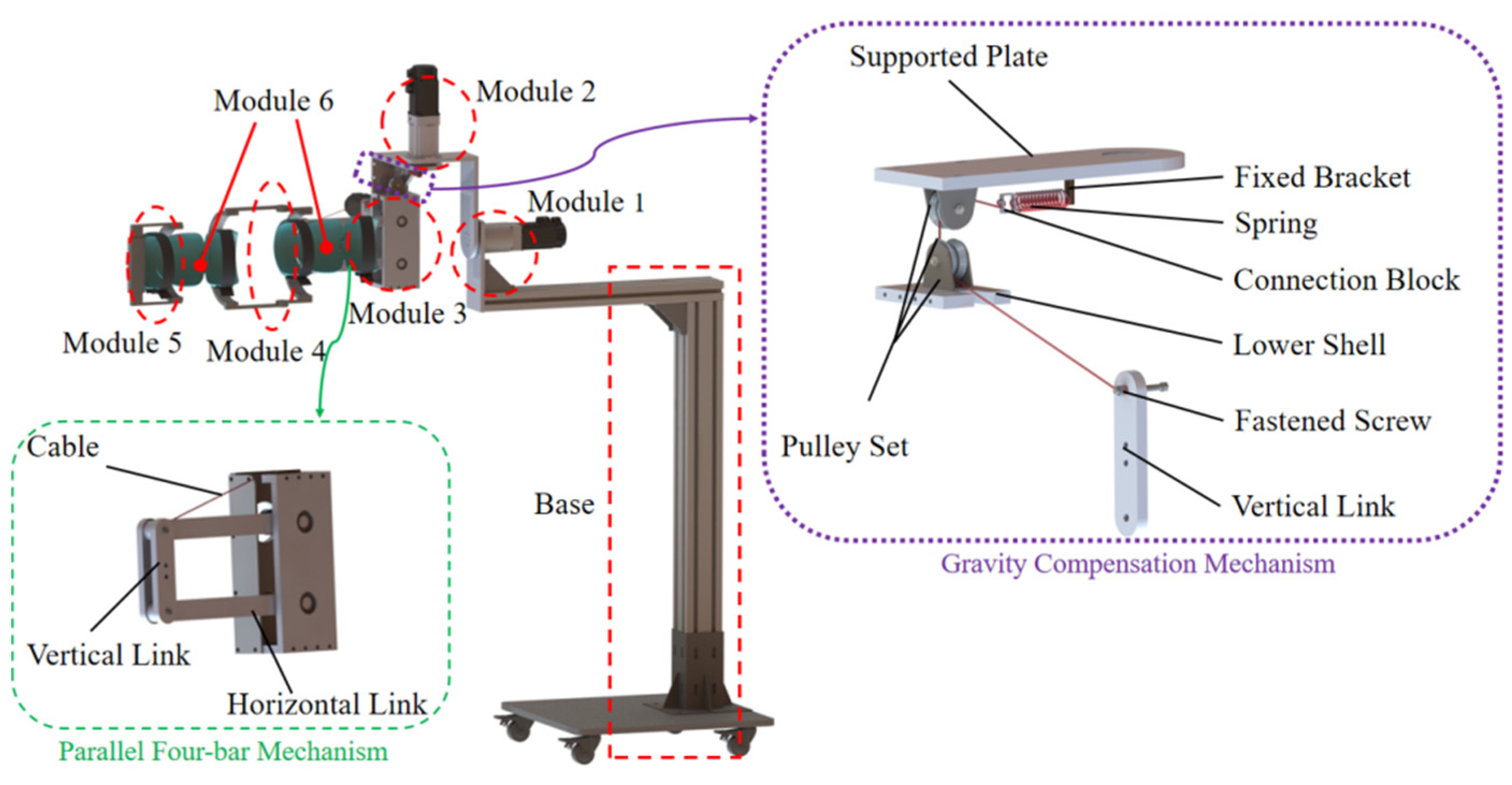
A six DoFs ULRR is designed for patients in the middle and late stages of stroke to conduct an in-depth analysis of the motion characteristics of each joint of the upper limbs. The upper limbs are moved by the robot to perform large-scale movements with multiple joints and implement active and passive rehabilitation training for stroke patients in the middle and late stages. The ULRR is composed of six modules, which is shown in Figure 5. Module 1 achieves the A/A motion of the SJ in the FP; module 2 achieves A/A motion of the SJ in the HP; module 3 achieves F/E motion of the SJ; module 4 achieves the F/E of the elbow; module 5 achieves the RUD and F/E motion of the wrist; and module 6 is the flexible straps that protect the patient’s hand. In module 3, a parallel four-bar linkage mechanism is designed to carry the axial load and improve the stability of the shoulder joint movement. During the rehabilitation training, the patient sits on the seat, then their upper limb is connected to the rehabilitation robot with flexible straps, and then their hand is connected to the end of the robot. The upper limb flexible straps play a role in immobilizing the upper limb and the rehabilitation robot, and its unique soft material greatly improves patient comfort during rehabilitation training. The SJ is an active joint driven by actuators, and the patient’s upper limbs are moved through the rehabilitation robot. The elbow and wrist joints are passive joints, and the patient drives the movement of the rehabilitation robot.
Meanwhile, a gravity compensation mechanism is installed for safety reasons. The mechanism is placed on the inside of the shoulder support. One end of the spring is fixed on the support plate of the shoulder, and the other end is connected to the wire-rope through the connecting piece. The wire-rope is fixed on the fastening screws of the flexion and extension rotating parts through the fixed pulley block, and the gravity compensation is realized by the tension of the spring, as shown in Figure 5. The gravity compensation mechanism can reduce the output torque of the motor and reduce the power consumption, and it can also protect the robot from performing the rehabilitation training. When the motor is powered off suddenly, the flexion and extension motion module of the rehabilitation robot falls down due to the action of gravity, causing secondary injury to the patient’s arm.
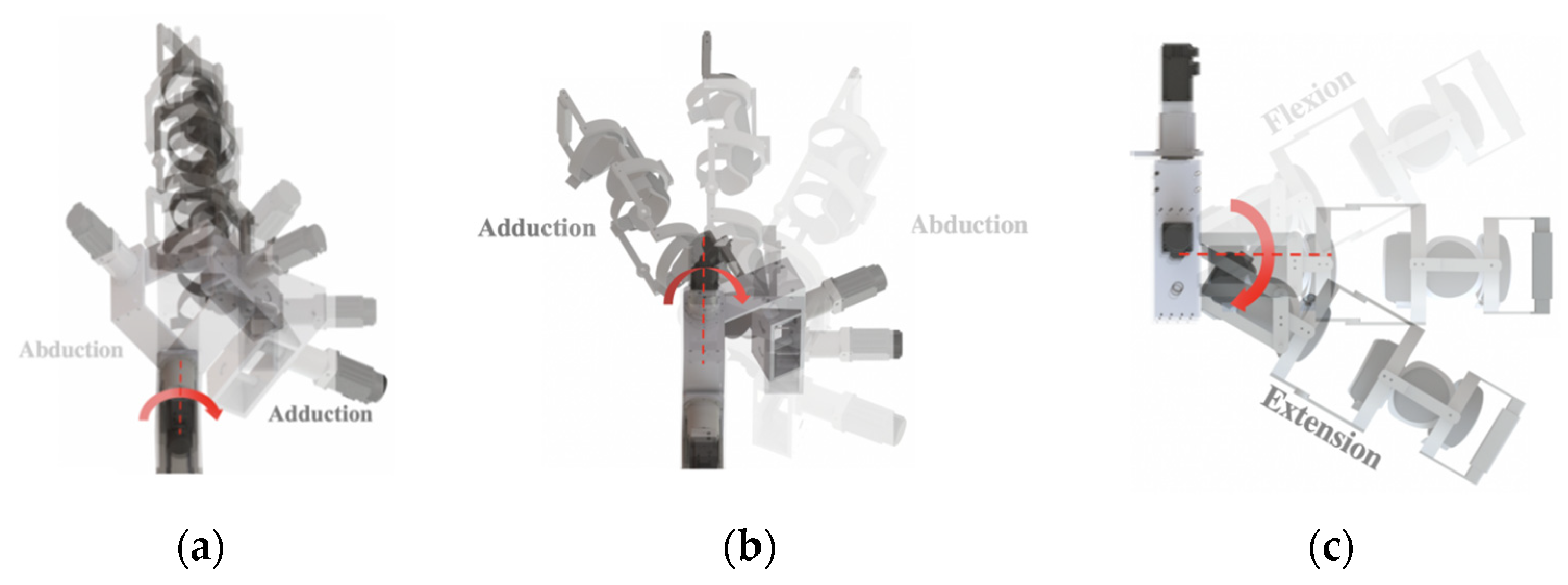
The traditional upper limb rehabilitation robot needs at least two movements to complete the A/A motion in the FP of the SJ. The first step completes the horizontal plane abduction, and then the second step completes the frontal plane motion. However, the ULRR accomplishes A/A motion of the SJ in the FP directly in one step. The design means the training time is shortened when completing the same movement; in other words, the number of movements is increased within the same amount of time. The schematic diagram of the movement is shown in Figure 6.

3. Kinematics and Simulation of the ULRR

3.1. Kinematic Analysis

The main objective of the forward kinematics of the robot is to solve the pose of the robot end effector by inputting the variable values of each joint given the robot configuration. The establishment of a forward kinematics equation is the premise of trajectory planning. In this paper, the kinematics of the ULRR is derived based on screw theory. In screw theory, the motion screw of a single ( i t h ) joint axis is known as ξ ^ i . According to the rigid body transformation matrix g = e ξ ^ θ , the rigid body, when it is transformed from one pose to another pose by rotation and translated along the motion screw axis ξ ^ i , can be expressed as
g a b ( θ ) = e ξ ^ i θ i g a b ( 0 )
where g a b ( 0 ) denotes the initial pose of the rigid body relative to the base coordinate system and g a b ( θ ) is the final pose of the transformed rigid body relative to the base coordinate system. If ξ ^ i corresponds to a rotating joint, then θ is the rotation angle around the axis, and if ξ ^ i corresponds to a translating joint, then θ is the translate length. ξ ^ i = [ ω ^ i v i 0 0 ] s e ( 3 ) , ω i denotes the unit directional vector of ξ ^ i , and v i is the position vector of ξ ^ i .
For a series robot with n joints, let {S} be the base coordinate system fixed on the base, {T} be the tool coordinate system of the end effector, and θ = 0 be the initial pose of the robot. When the robot is in the initial pose, the pose of {T} relative to {S} is represented by g s t ( 0 ) , and after the robot moves, the pose of {T} relative to {S} is represented by g s t ( θ ) . For each joint, a unit motion screw ξ ^ i can be constructed to represent the screw motion of the i th joint. According to the Formula (1), when combining the motion of each joint, the Product of Exponential (PoE) Formula of the forward kinematics of the robot is obtained as:
g s t ( θ ) = e ξ ^ 1 θ 1 e ξ ^ 2 θ 2 e ξ ^ n θ n g s t ( 0 )
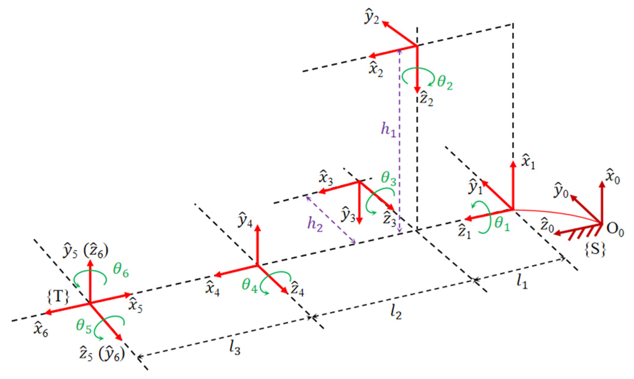
Based on screw theory, the 6-DoFs rehabilitation robot can be described as the rotation of an instantaneous screw axis ξ i by the rotation angle θ i . From Figure 7, the kinematics transformation of the ULRR is
g s t ( θ ) = e ξ ^ 1 θ 1 e ξ ^ 2 θ 2 e ξ ^ 3 θ 3 e ξ ^ 4 θ 4 e ξ ^ 5 θ 5 e ξ ^ 6 θ 6 g s t ( 0 )
The initial pose g s t ( 0 ) and e ξ ^ i θ i of the robot can be obtained as
g s t ( 0 ) = [ 1 0 0 0 0 1 0 0 0 0 1 L 0 0 0 1 ]
e ξ ^ 1 θ 1 = [ cos θ 1 sin θ 1 0 0 sin θ 1 cos θ 1 0 0 0 0 1 0 0 0 0 1 ] e ξ ^ 2 θ 2 = [ 1 0 0 0 0 cos θ 2 sin θ 2 l 1 sin θ 2 0 sin θ 2 cos θ 2 l 1 ( 1 cos θ 2 ) 0 0 0 1 ] e ξ ^ 3 θ 3 = [ cos θ 3 0 sin θ 3 l 1 sin θ 3 0 1 0 0 sin θ 3 0 cos θ 3 l 1 ( 1 cos θ 3 ) 0 0 0 1 ] e ξ ^ 4 θ 4 = [ cos θ 4 0 sin θ 4 ( l 1 + l 2 ) sin θ 3 0 1 0 0 sin θ 4 0 cos θ 4 ( l 1 + l 2 ) ( 1 cos θ 4 ) 0 0 0 1 ] e ξ ^ 5 θ 5 = [ cos θ 5 0 sin θ 5 L sin θ 5 0 1 0 0 sin θ 5 0 cos θ 5 L ( 1 cos θ 5 ) 0 0 0 1 ] e ξ ^ 6 θ 6 = [ 1 0 0 0 0 cos θ 6 sin θ 6 L sin θ 6 0 sin θ 6 cos θ 6 L ( 1 cos θ 6 ) 0 0 0 1 ]
where L = l 1 + l 2 + l 3
The forward kinematics of the ULRR can be obtained by taking Equation (5) into Equation (3).

3.2. Simulation Analysis

3.2.1. Feasibility and Stationarity Analysis

To verify the feasibility of the designed ULRR and the stability of the model in the movement process, the simplified 3D model is imported into ADAMS software. The torque of each joint and the center mass of the robot end are selected as the measurement objects, while the principal moments of inertia of each joint are obtained, as Table 2 shows, and the overall motion time is set to 10 s. Figure 8 shows the simulation results, which include the torque of each joint, the displacement of the end center of mass, the angular velocity, and the angular acceleration curves.
Figure 8a is the time-varying curve of the torque during joint motion, and Figure 8b is the time-varying curve of the angular velocity and angular acceleration of the robot end. In Figure 8a, Joint_1, Joint_2, and Joint_3 are the torque change curves during the motion of the SJ with three DoFs, and Joint_4 is the torque change curve during the elbow joint movement. During the entire process, the curves are relatively smooth, and the joint torque does not fluctuate much and eventually tends to be stable. The torque required for the elbow and wrist joint movement is extremely minor, so the curves hardly change. Figure 8c shows the curves of the end displacement with time. It can be seen from the curves that the maximum displacement the robot can achieve in the X, Y, and Z directions are 708 mm, 715 mm, and 550 mm, respectively. The simulation results illustrate that the ULRR is relatively stable during the entire process and the end movement trajectory is continuous. The curves do not have any sudden change in the motional stage, and the change of the curve conforms to the reality. Therefore, the ULRR designed in this paper is reasonable and stable, and there is no interference in the mechanisms.

3.2.2. Verification of the Convenience of the Rehabilitation Process

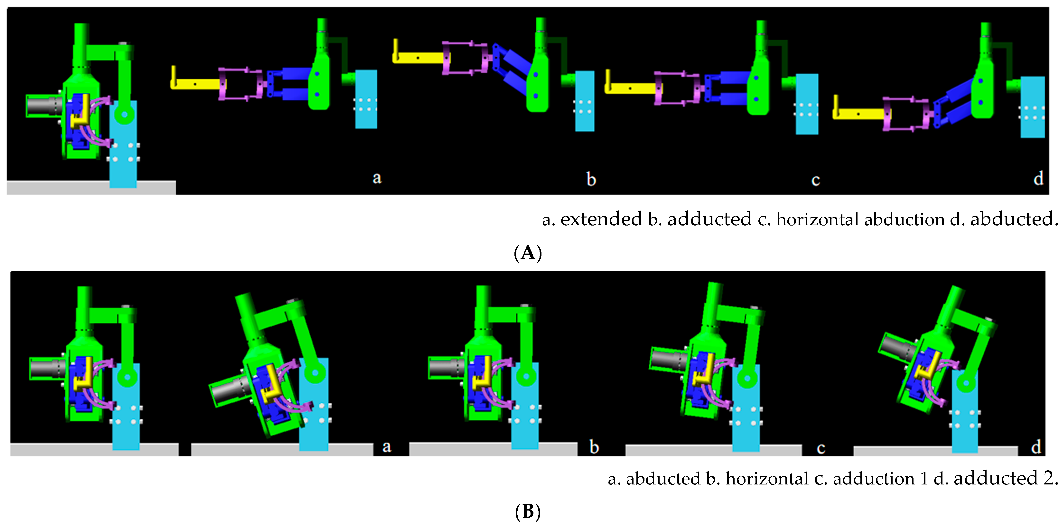
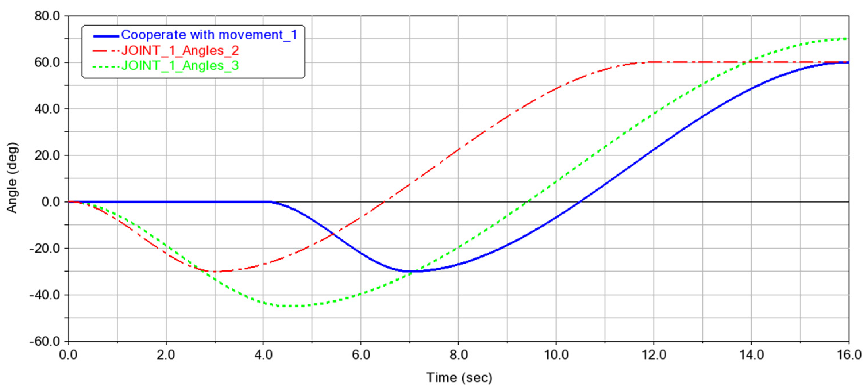
In order to verify that the ULRR needs less time to complete the A/A motion in the FP of the SJ, the SJ is selected as the measurement object, the simulation time is set to 16 s, and the movement is carried out by constant angular velocity. The simulation process is shown in Figure 9. The simulation process of compound motion in Figure 9a is to imitate the traditional robot to complete the A/A motion in FP. From the initial state, the arm is extended 90° externally, and then adducted 30° in FP. Figure 9b shows the motion process when the A/A motion of the SJ is directly completed. It directly adducted 30° from the initial state and then reversely rotated 90°.
Figure 10 shows the results of the simulation curves. The blue curve is the change of the angle over time during the coordinated movement. Zero to four seconds is the process of the arm opening, and the robot does not move in the FP. The robot starts to do the A/A motion after the fourth second. The red and green curves are the angle changing over time when the SJ completed the A/A motion directly. It can be seen from Figure 10 that the time required for the SJ completed A/A motion to the same angle is reduced by 4 s compared to the coordination to complete the movement. When the motion time is the same, it adds 15 degrees and 10 degrees more for adduction and abduction, respectively. Therefore, the ULRR is more convenient in the A/A motion of SJ. Patients can do more movements at the same time during rehabilitation training.

3.3. Workspace of the ULRR

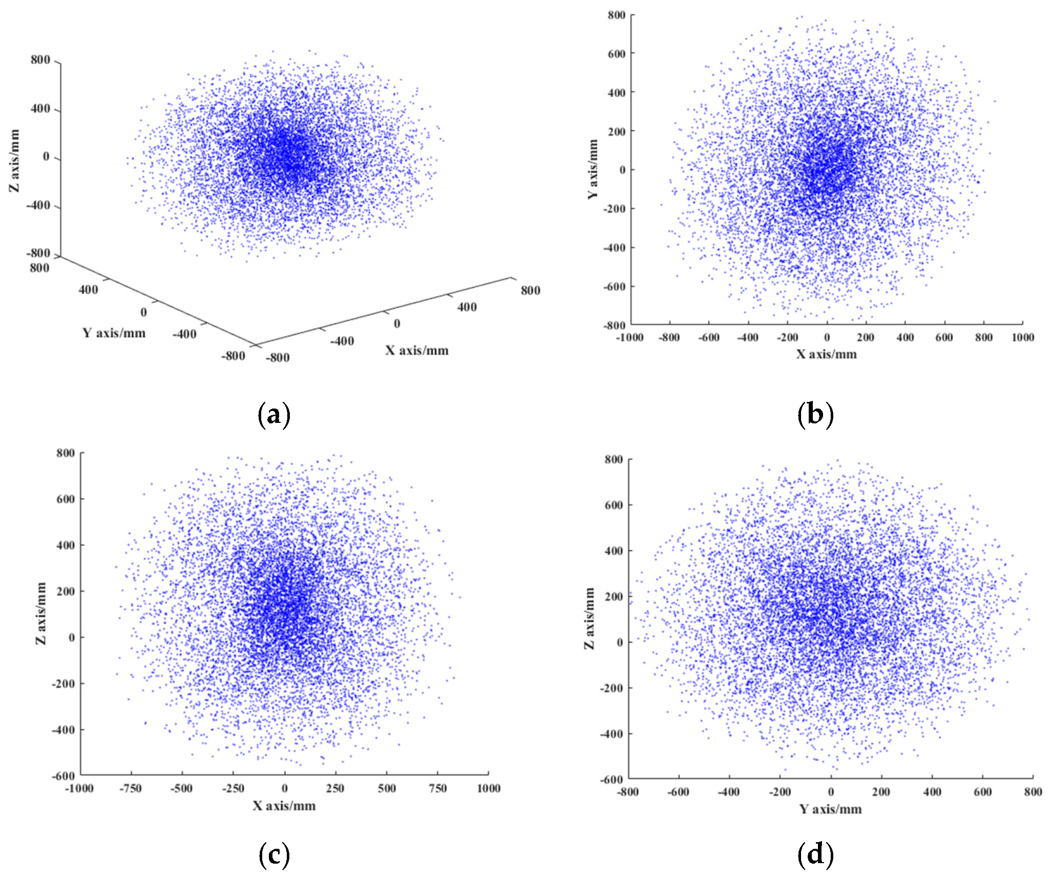
The workspace of the robot is an important basis to measure whether the design of the rehabilitation robot is reasonable. In the process of rehabilitation training, the workspace of the robot needs to meet the maximum range of motion of the upper limbs of the human body. The Monte Carlo method is used to obtain the workspace of the robot by combining the kinematic equations and the motion range of each joint angle. The simulation results are shown in Figure 11. From the simulation results, the range of workspace that is accessible to the end of the robot is: 730   mm X 730   mm , 730   mm Y 730   mm , and 556   mm Z 556   mm . It is known from ergonomics that the limit position of the robot is near the limit position of dynamic of the upper limb of the human body. Therefore, the designed ULRR fulfills the requirements of the upper limb rehabilitation exercise.

4. Trajectory Planning of the ULRR

In order to better realize the rehabilitation function of the ULRR in the process of rehabilitation training, it is necessary to plan the movement trajectory of the robot. When the movement path of the robot is small or there are no obstacles during the movement, it is only necessary to move the robot from the initial point to the end point, and path planning can be used directly for path control. Trajectory planning can enhance the stability and the accuracy of the robot during the rehabilitation training process, thereby reducing the vibration generated from the robot motion.

4.1. Trajectory Planning of Joint Space

Since the DoFs of the robot in this paper are not complicated, complex high-order polynomial and b-spline interpolation methods are not required for trajectory planning. The angular acceleration of the joint is not definitely constrained when the trajectory planning is performed by the cubic polynomial interpolation method. However, in the actual operation of the system, the angular acceleration of the joint influences the stability of the start and stop of the system. Therefore, this paper adopts the quintic polynomial interpolation method for trajectory planning. The quintic polynomial has more constraints on acceleration than the cubic polynomial which solves problems, including that the angular velocity of the cubic polynomial is not stable and the angular acceleration suddenly changes. The position, velocity, and acceleration constraint functions of the initial point and the end point in the quintic polynomial can be expressed as:
θ ( t ) = x 0 + x 1 t + x 2 t 2 + x 3 t 3 + x 4 t 4 + x 5 t 5
θ ˙ ( t ) = x 1 + 2 x 2 t + 3 x 3 t 2 + 4 x 4 t 3 + 5 x 5 t 4
θ ¨ ( t ) = 2 x 2 + 6 x 3 t + 12 x 4 t 2 + 20 x 5 t 3
To solve the unknowns in the quintic polynomial, it is necessary to specify the value at the time of the initial point and the value at the time of the end point. To ensure that the trajectory transition of the ULRR is smooth and continuous during the process of rehabilitation training, the constraints are as follows:
{ θ ( t 0 ) = θ 0 θ ˙ ( t 0 ) = 0 θ ¨ ( t 0 ) = 0 θ ( t b ) = θ b θ ˙ ( t b ) = 0 θ ¨ ( t b ) = 0
And get the results as follows:
{ x 0 = θ 0 x 1 = θ ˙ 0 x 2 = θ ¨ 0 2 x 3 = 20 θ b 20 θ 0 ( 8 θ ˙ b + 12 θ ˙ 0 ) t b ( 3 θ ¨ 0 θ ¨ b ) t b 2 2 t b 3 x 4 = 30 θ b 30 θ 0 ( 14 θ ˙ b + 16 θ ˙ 0 ) t b ( 3 θ ¨ 0 2 θ ¨ b ) t b 2 2 t b 4 x 5 = 12 θ b 12 θ 0 ( 6 θ ˙ b + 6 θ ˙ 0 ) t b ( θ ¨ 0 θ ¨ b ) t b 2 2 t b 5

4.2. Trajectory Planning of Cartesian Space

The trajectory planning of the joint space can plan the rehabilitation training movements with smaller amplitude. During daily rehabilitation training of patients, more complex rehabilitation movements are required. However, the trajectory planning of the joint space with polynomial interpolation cannot achieve the planning effect [30]. Thus, it is necessary to carry out more precise requirements for the trajectory path of the rehabilitation robot to meet more scientific and reasonable training tasks. The trajectory planning of the ULRR is carried out in Cartesian space, and the prescribed rehabilitation training actions are completed within the prescribed time. The general trajectory planning methods in Cartesian space include space linear interpolation method, space arc interpolation method, neural network method, etc. The spatial linear interpolation method has the advantages of stability, a simple structure, and easy implementation, and it is suitable for trajectory planning of simple actions. Therefore, the spatial linear interpolation method is used for trajectory planning in Cartesian space. The curve in any space is divided into small space straight lines, then the space straight lines are interpolated, and then the interpolation points are transferred to space joints for trajectory planning in Cartesian space.
Assuming that the three-dimensional coordinates of the starting two points of the trajectory in the space are M ( x 0 , y 0 , z 0 ) and N ( x b , y b , z b ) , respectively, the motion speed of the straight line is v and the fixed interpolation time interval is t . The positions and attitudes of the points M and N are known, and the straight-line distance H between the two points and the interpolation distance l of the time period t are calculated.
H = ( x b x 0 ) 2 + ( y b y 0 ) 2 + ( z b z 0 ) 2
l = v t
Then the total interpolation number G is calculated as:
G = H l + 1
The increments of adjacent interpolation points in each axis are as follows:
{ Δ x = x b x 0 G Δ y = y b y 0 G Δ z = z b z 0 G
Finally, the coordinates of the interpolation point are obtained as follows:
{ x i + 1 = x i + i Δ x y i + 1 = y i + i Δ y z i + 1 = z i + i Δ z

4.3. Simulation of Trajectory Planning

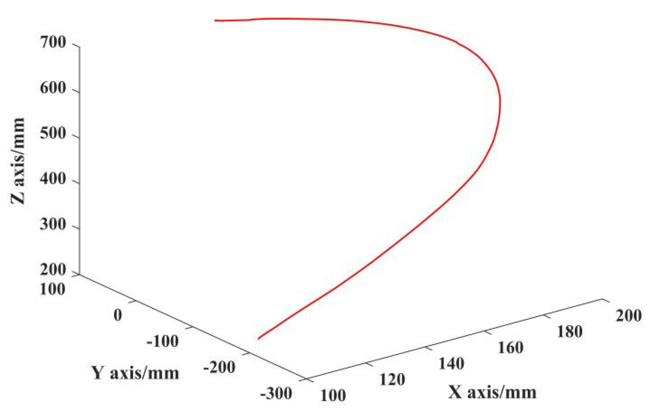
The trajectory planning of joint space and Cartesian space is carried out for the ULRR taking the action of drinking water as an example. According to the actual action situation, the initial joint angles of the drinking action are set as: 22°, 0°, 0°, 0°, 0°, and 0°. According to the quintic polynomial interpolation and the spatial linear interpolation function, the trajectory planning of the act of drinking water is carried out in Matlab software. When the human body is drinking, most of the joints of the upper limbs are involved in the movement and achieve a certain angle of movement. The movement time is set to 10 s, and the trajectory curve of the Cartesian space is obtained as shown in Figure 12.
Figure 12 is the change curve of the angle of each joint after trajectory planning in the joint space, where (a), (b), and (c) are the angle changes of the three DoFs of the SJ; (d) is the change of the F/E angle of the elbow; (e) is the change of the RUD angle of the wrist joint; and (f) is the change of the F/E angle of the wrist joint. Figure 13 shows the trajectory curve of drinking water in Cartesian space. It can be seen from Figure 12 and Figure 13 that the transition between the angle curve of each joint of the robot and the movement trajectory is smooth and the discrete points of the curve are consistent with the curve after interpolation, which ensures the stability and the accuracy of the trajectory during the robot movement and meets the trajectory planning requirements.

5. Rehabilitation Training Experiment

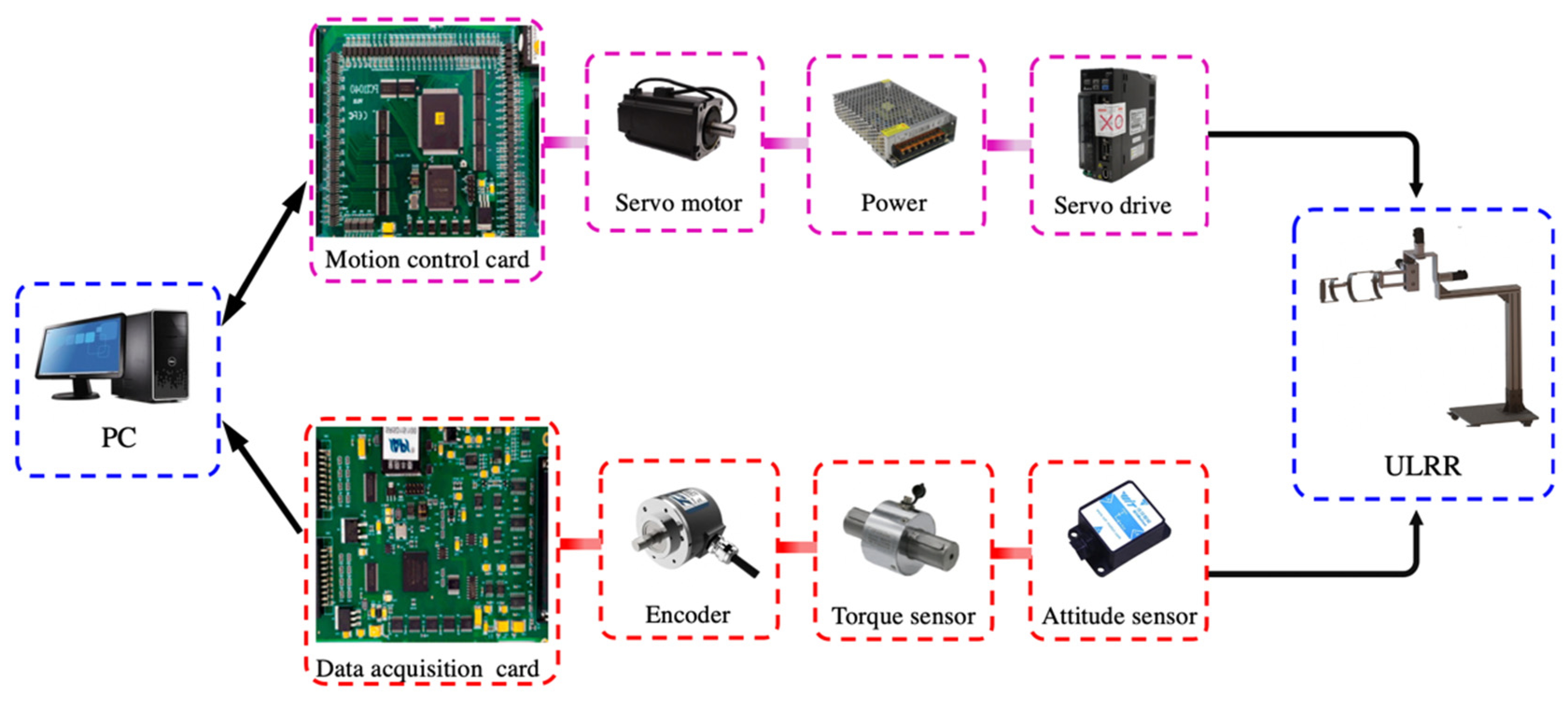
To realize the control of the ULRR using the computer, the diagram of the ULRR control system is shown in Figure 14. The key factors of the control system are the motion control and the data acquisition card which are used to collect the data of motion. After data collection by sensors is transmitted to the data acquisition, the data acquisition card converts the acquired data into motion parameters through calculation, and then the motor rotation information outputs to each servo drive through the motion control card.

5.1. Training experiment of the A/A motion of SJ in FP

During the A/A motion of SJ in FP training, the participant is a healthy adult male with a symmetrical figure. The movement time of the shoulder joint of the upper limb rehabilitation robot with three DoFs is set to 30 s, as shown in Figure 15. The Qualisys Track Manager (QTM) system collects the participant’s range of motion (ROM) of the ULRR. Figure 16 shows the ROM of the A/A motion of SJ in FP.

5.2. Training Experiment of Multi-Joint Compound

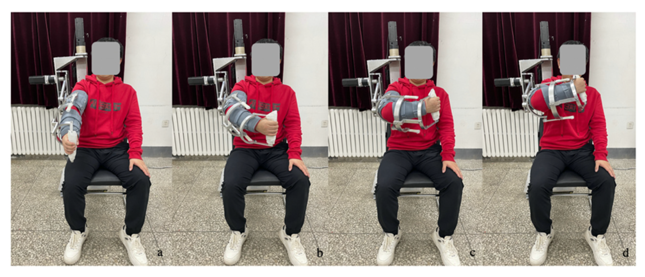
The ultimate goal of the patient’s rehabilitation is that the patient can complete the basic activities required during daily life. Therefore, it is necessary that multi-joint compound movements are trained in rehabilitation training. Taking the basic action of drinking water as an example, a multi-joint compound exercise rehabilitation training experiment is carried out. The experimental process is shown in Figure 17.
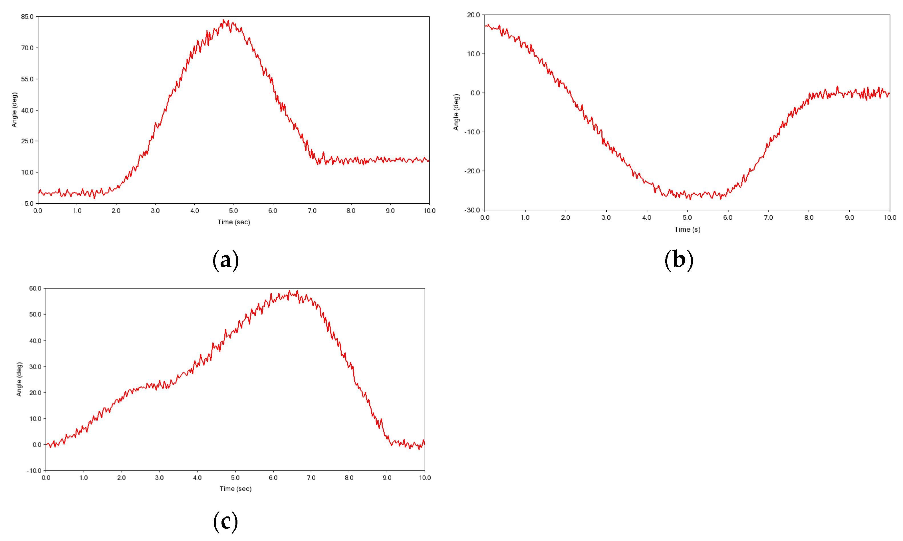
The values of the SJ are collected when the participant completes the action of drinking water, as shown in Figure 18. The results demonstrate that during the experiment, the movement of the robot follows the expected trajectory, the robot can successfully complete the set action, and there is no interference between the ULRR and the participant.

5.3. Training Experiment of Active Rehabilitation

The active rehabilitation training experiment is a rehabilitation training experiment in which the robot does not provide any driving force and the ULRR is driven by the participants to move independently. The ULRR is suitable for patients with certain muscle strength in the middle and late stages of stroke. Through active rehabilitation training experiments, the muscle ability of patients can be improved and the effect of muscle strength training can be enhanced. In the training experiment of active rehabilitation, the participants imitated the action of the patient touching the left shoulder with the right hand. The experimental process is shown in Figure 19.
The participant accomplished the rehabilitation exercise of touching the left shoulder, and the values of the angles of the threes movement of the SJ were collected, as shown in Figure 20. Figure 20 shows the curves of the angles of three movements of the SJ over time during the rehabilitation exercise of touching the left shoulder. The experimental results show that the participants can successfully complete the movement of touching the left shoulder, and the changes of the angle of each joint are in line with the actual situation. The rationality and feasibility of the rehabilitation robot are verified. After the participant completes the training exercises, the participant is asked about their subjective feelings of comfort. The comfort of the upper limbs during the exercise is used as the evaluation standard, which includes good, average, fair, and poor. The participant’s subjective feeling is average, indicating that there is no physical discomfort during the participant’s training.

6. Conclusions

In this paper, a ULRR is proposed for middle and late stage stroke patients. Firstly, the structure of the shoulder, elbow, and wrist joint are designed to realize the rehabilitation training movement of the rehabilitation robot by analyzing the joint configuration of the human body. There are three actuators on the SJ to complete the A/A motion in the FP in one step, which can increase the efficiency of rehabilitation training. Then, the kinematic parameter model of the robot is established by the PoE method, and the kinematic equations are derived. Adams is used to simulate the virtual prototype of the rehabilitation robot. The simulation results illustrate that the robot is stable in the process of the entire movement and the movement trajectory is minor and continuous without interruption. The two movement modes of the SJ in the frontal plane of adduction and abduction are compared and analyzed. The results show that the ULRR takes less time to complete the A/A movement directly than it takes to coordinate the movement to the same angle. Significantly, the ULRR can complete more movements within the same amount of time, and the SJ is more flexible when performing compound movements. The workspace of the robot is analyzed, and the simulation results show that its workspace is close to the motion range of the upper limbs of the human body. It is verified that the motion range of the ULRR is consistent with that of human upper limbs. Furthermore, the trajectory of the robot to complete the act of drinking water is planned, and the simulation curve is relatively stable. Finally, the ULRR prototype is experimentally verified, and the results show that the robot has no interference during the motional process, which can satisfy the rehabilitation training of the patients.

Author Contributions

Conceptualization, S.L. and Z.W.; methodology, software, and validation, Z.D.; formal analysis and investigation, M.G.; resources and data curation, S.L. and Z.P.; writing—original draft preparation, S.L.; writing—review and editing, Z.P.; visualization, supervision, project administration, and funding acquisition, Z.W. All authors have read and agreed to the published version of the manuscript.

Funding

This research was funded by the National Natural Science Foundation of China, grant number 51875047, and the Foundation of Jilin Provincial Science and Technology, grant number 20220204102YY.

Data Availability Statement

Not applicable.

Acknowledgments

The authors would like to thank the National Natural Science Foundation of China (NSFC) under Grant No. 51875047 and Foundation of Jilin Provincial Science and Technology under Grant No. 20220204102YY for their financial support. The authors are grateful to the anonymous reviewers and the Editor for their valuable comments and suggestions on improving this paper.

Conflicts of Interest

The authors declare no conflict of interest.

References

  1. Tsao, C.W.; Aday, A.W.; Almarzooq, Z.I.; Alonso, A.; Beaton, A.Z.; Bittencourt, M.S.; Boehme, A.K.; Buxton, A.E.; Carson, A.P.; Commodore-Mensah, Y.; et al. Heart Disease and Stroke Statistics-2022 Update: A Report From the American Heart Association. Circulation 2022, 145, e153–e639. [Google Scholar] [CrossRef] [PubMed]
  2. Rana, J.S.; Khan, S.S.; Lloyd-Jones, D.M.; Sidney, S. Changes in Mortality in Top 10 Causes of Death from 2011 to 2018. J. Gen. Intern. Med. 2020, 36, 2517–2518. [Google Scholar] [CrossRef] [PubMed]
  3. Milot; Marie-Hélène; Cramer, S.C. Recovery after Stroke. Stroke 2019, 50, 654–659. [Google Scholar]
  4. Mandeville, R.M.; Brown, J.M.; Sheean, G.L. A neurophysiological approach to nerve transfer to restore upper limb function in cervical spinal cord injury. Neurosurg. Focus 2017, 43, E6. [Google Scholar] [CrossRef] [Green Version]
  5. BlankA, A.; French, J.A.; Pehlivan, A.U.; O’Malley, M.K. Current Trends in Robot-Assisted Upper-Limb Stroke Rehabilitation: Promoting Patient Engagement in Therapy. Curr. Phys. Med. Rehabil. Rep. 2014, 2, 184–195. [Google Scholar] [CrossRef]
  6. Pang, Z.; Wang, T.; Yu, J. Design and analysis of shoulder joint exoskeleton rehabilitation mechanism based on gear and rack transmission. AIP Adv. 2021, 11, 055122. [Google Scholar] [CrossRef]
  7. Yochelson, M.R.; Dennisonsr, A.C.; Kolarova, A.L. Stroke Rehabilitation, 6th ed.; Elsevier: Maryland Heights, MO, USA, 2021; pp. 2–47. [Google Scholar]
  8. Marco, G.; Alexander, D.W.; Simon, B.; Verena, K.M.; Tobias, N.; Rober, R. A robotic system to train activities of daily living in a virtual environment. Med. Biol. Eng. 2011, 49, 1213–1223. [Google Scholar]
  9. Mao, Y.; Agrawal, S.K. Design of a Cable-Driven Arm Exoskeleton (CAREX) for Neural Rehabilitation. IEEE Trans. Robot. 2012, 28, 922–931. [Google Scholar] [CrossRef]
  10. Mao, Y.; Agrawal, S.K. Transition from mechanical arm to human arm with CAREX: A cable driven ARm EXoskeleton (CAREX) for neural rehabilitation. In Proceedings of the IEEE International Conference on Robotics and Automation, Saint Paul, MN, USA, 14–18 May 2012; pp. 2457–2462. [Google Scholar] [CrossRef]
  11. Tang, Z.C.; Zhang, K.J.; Sun, S.Q.; Gao, Z.G.; Zhang, L.K.; Yang, Z.L. An upper-limb power-assist exoskeleton using proportional myoelectric control. Sensors 2014, 14, 6677–6694. [Google Scholar] [CrossRef] [Green Version]
  12. Gull, M.A.; Bai, S.; Bak, T. A Review on Design of Upper Limb Exoskeletons. Robotics 2020, 9, 16. [Google Scholar] [CrossRef] [Green Version]
  13. Liu, Y.-C.; Takeda, Y. Kineto-Static Analysis of a Wrist Rehabilitation Robot with Compliance and Passive Joints for Joint Misalignment Compensation. Machines 2020, 8, 23. [Google Scholar] [CrossRef]
  14. Singh, N.; Saini, M.; Anand, S.; Kumar, N.; Srivastava, M.V.P.; Mehndiratta, A. Robotic Exoskeleton for Wrist and Fingers Joint in Post-Stroke Neuro-Rehabilitation for Low-Resource Settings. IEEE Trans. Neural Syst. Rehabil. Eng. 2019, 27, 2369–2377. [Google Scholar] [CrossRef] [PubMed]
  15. Li, Z.J.; Su, C.Y.; Wang, L.Y.; Chen, Z.T.; Chai, T.Y. Nonlinear disturbance observer-based control design for a robotic exoskeleton incorporating fuzzy approximation. IEEE Trans. Ind. Electron. 2015, 62, 5763–5775. [Google Scholar] [CrossRef]
  16. Tian, Y.; Wang, H.; Niu, B.; Zhang, Y.; Du, J.; Niu, J.; Sun, L. Mechanical Design and Analysis of the End-Effector Finger Rehabilitation Robot (EFRR) for Stroke Patients. Machines 2021, 9, 110. [Google Scholar] [CrossRef]
  17. Huang, J.; Huo, W.G.; Xu, W.X.; Samer, M.; Yacine, A. Control of upper-limb power-assist exoskeleton using a human-robot interface based on motion intention recognition. IEEE Trans. Autom. Sci. Eng. 2015, 12, 1257–1270. [Google Scholar] [CrossRef]
  18. Liu, Y.-C.; Irube, K.; Takeda, Y. Kineto-Static Analysis and Design Optimization of a 3-DOF Wrist Rehabilitation Parallel Robot with Consideration of the Effect of the Human Limb. Machines 2021, 9, 323. [Google Scholar] [CrossRef]
  19. Colomer, C.; Baldoví, A.; Torromé, S.; Navarro, M.D.; Moliner, B.; Ferri, J.; Noé, E. Efficacy of Armeo® Spring during the chronic phase of stroke. Study in mild to moderate cases of hemiparesis. Neurología 2013, 28, 261–267. [Google Scholar] [CrossRef]
  20. Gijbels, D.; Lamers, I.; Kerkhofs, L.; Alders, G.; Knippenberg, E.; Feys, P. The Armeo Spring as training tool to improve upper limb functionality in multiple sclerosis: A pilot study. J. NeuroEng. Rehabil. 2011, 8, 5. [Google Scholar] [CrossRef] [Green Version]
  21. Sicuri, C.; Porcellini, G.; Merolla, G. Robotics in shoulder rehabilitation. Muscles Ligaments Tendons J. 2014, 4, 207–213. [Google Scholar] [CrossRef]
  22. Ergin, M.A.; Patoglu, V. ASSISTON-SE: A self-aligning shoulder-elbow exoskeleton. In Proceedings of the IEEE International Conference on Robotics & Automation, Saint Paul, MN, USA, 14–18 May 2012; pp. 2479–2485. [Google Scholar] [CrossRef]
  23. Haraguchi, M.; Sonobe, M.; Mihara, M. Tracking Training and Its Assessment Using 3D Rehabilitation System for Upper Limbs “EMUL” and Brain Function Imaging Method “MRS”. In Proceedings of the JSME Annual Conference on Robotics and Mechatronics (Robomec), Asahikawa, Japan, 13–16 June 2010. [Google Scholar] [CrossRef]
  24. Tsuji, T.; Yokoo, T. Compilation of Joint Motion Database using Upper Limb Rehabilitation Robot (Rehabilitation Robotics and Mechatronics (2)). In Proceedings of the JSME Annual Conference on Robotics and Mechatronics (Robomec), Hamamatsu, Japan, 27–29 May 2012. [Google Scholar] [CrossRef]
  25. Pehlivan, A.U.; Rose, C.; O’Malley, M.K. System characterization of RiceWrist-S: A forearm-wrist exoskeleton for upper extremity rehabilitation. In Proceedings of the IEEE International Conference on Rehabilitation Robotics (ICORR), Seattle, WA, USA, 24–26 June 2013; pp. 1–6. [Google Scholar] [CrossRef]
  26. Fitle, K.D.; Pehlivan, A.U.; O’Malley, M.K. A robotic exoskeleton for rehabilitation and assessment of the upper limb following incomplete spinal cord injury. In Proceedings of the IEEE International Conference on Robotics and Automation (ICRA), Seattle, WA, USA, 26–30 May 2015; pp. 4960–4966. [Google Scholar] [CrossRef]
  27. Kadivar, Z.; Sullivan, J.L.; Eng, D.P. RiceWrist Robotic Device for Upper Limb Training: Feasibility Study and Case Report of Two Tetraplegic Persons with Spinal Cord Injury. Int. J. Biol. Eng. 2012, 2, 27–38. [Google Scholar] [CrossRef] [Green Version]
  28. Pehlivan, A.U.; Sergi, F.; Erwin, A. Design and validation of the RiceWrist-S exoskeleton for robotic rehabilitation after incomplete spinal cord injury. Robotica 2014, 32, 1415–1431. [Google Scholar] [CrossRef] [Green Version]
  29. Neumann, D.A. Essentials of Kinesiology for the Physical Therapist Assistant, 3rd ed.; Elsevier: Maryland Heights, MO, USA, 2019; pp. 175–249. [Google Scholar]
  30. Qie, X.; Kang, C.; Zong, G.; Chen, S. Trajectory Planning and Simulation Study of Redundant Robotic Arm for Upper Limb Rehabilitation Based on Back Propagation Neural Network and Genetic Algorithm. Sensors 2022, 22, 4071. [Google Scholar] [CrossRef] [PubMed]
Figure 1. The three planes and axis of the body.
Machines 10 01035 g001
Figure 2. The overall structure of upper limb.
Machines 10 01035 g002
Figure 3. Basic DoFs of human upper limbs. (a) F/E motion in the SP of the SJ; (b) A/A in the HP of the SJ; (c) A/A in the FP of the SJ; (d) F/E of the elbow joint; (e) RUD and F/E of the wrist.
Machines 10 01035 g003
Figure 4. The schematic diagram of the ULRR.
Machines 10 01035 g004
Figure 5. Overall structure of the ULRR.
Machines 10 01035 g005
Figure 6. The schematic diagram of SJ motion of the ULRR: (a) A/A in the FP; (b) A/A in the HP; (c) F/E in the SP.
Machines 10 01035 g006
Figure 7. Mechanism diagram of the ULRR.
Machines 10 01035 g007
Figure 8. Adams simulation curve of the upper limb rehabilitation robot: (a) the torque curves of each joint; (b) the curves of acceleration and angular acceleration at the end; and (c) the curves of end displacement.
Machines 10 01035 g008
Figure 9. Schematic diagram of the simulation process A/A motion of SJ: (A) compound motion process and (B) direct motion process.
Machines 10 01035 g009
Figure 10. The change curve of the adduction/abduction motion angle over time.
Machines 10 01035 g010
Figure 11. Cloud map of the ULRR workspace: (a) the Cartesian 3D space; (b) XOY plane of 2D space; (c) XOZ plane of 2D space; and (d) YOZ plane of 2D space.
Machines 10 01035 g011
Figure 12. Simulation of joint space trajectory planning: (af) are the angle curves of Joint_1 to Joint_6, respectively.
Machines 10 01035 g012
Figure 13. Simulation of Cartesian space trajectory planning.
Machines 10 01035 g013
Figure 14. The diagram of the control system.
Machines 10 01035 g014
Figure 15. The training progress of A/A motion of SJ in FP: (a) initial pose; (b) adduction; (c) abduction; and (d) back to the initial pose.
Machines 10 01035 g015
Figure 16. The ROM of A/A motion of SJ in FP.
Machines 10 01035 g016
Figure 17. Rehabilitation exercise: (a) initial pose; (b) process of raising hand 1; (c) process of raising hand 2; and (d) finish the action of drinking water.
Machines 10 01035 g017
Figure 18. Multi-joint compound rehabilitation training experiment of the ULRR: (a) F/E in the SP of the shoulder join; (b) A/A in the FP of the SJ; and (c) A/A in the HP of the SJ.
Machines 10 01035 g018
Figure 19. Active rehabilitation training experiments: (a) initial pose; (b) process of raising hand 1; (c) process of raising hand 2; and (d) finish the action of touching the shoulder.
Machines 10 01035 g019
Figure 20. Experimental results of the active rehabilitation training of the ULRR: (a) F/E in the SP of the shoulder join; (b) A/A in the HP of the SJ; and (c) A/A in the FP of the SJ.
Machines 10 01035 g020
Table 1. The range of freedom of motion of each joint of the upper extremity.
JointDoFsHumanRobot
ShoulderF/E in the SP0–180°/0–60°0–120°/0–45°
A/A in the HP0–75°/0–90°0–45°/0–90°
A/A in the FP0–50°/0–180°0–45°/0–135°
ElbowF/E0–135°0–100°
WristRUD0–20°/0–35°0–20°/0–30°
F/E0–50°/0–40°0–50°/0–40°
Table 2. The principal moments of inertia of the ULRR.
Joint I xx   ( k g · m m 2 ) I yy   ( k g · m m 2 ) I zz   ( k g · m m 2 )
16.864023 × 1046.244685 × 1043.370621 × 104
22.783526 × 1042.500916 × 1041.038952 × 104
30.577064 × 1040.452236 × 1040.237761 × 104
Publisher’s Note: MDPI stays neutral with regard to jurisdictional claims in published maps and institutional affiliations.