1. Introduction
With the rapid development of aerospace industry, the production mode of aerospace engines is tending to be multi-type in small and medium batches. Aerospace engines have extremely high requirements on the assembly process. Bolt tightening [
1,
2] is one of the most widely used important processes in engine assembly. It has high research value and has been widely concerned by experts and scholars.
Liu [
3] established a mechanical model of the connection structure. To study the modal characteristics and steady-state dynamic response of an engine system with a bolted connection, state space theory and numerical calculation methods are applied to numerically simulate. To study the mechanical behavior and stress state of the high strength bolt friction grip long joint, Zhang [
4] studied fourteen different bolted connections with the three-dimensional finite element analysis which is based on the general FE software ANSYS. Cai [
5] conducted research on bolt tightening of composite material structures under different working conditions. Through theoretical analysis and experimental verification, it is concluded that different tightening conditions have a great influence on the clamping force during the bolt connection process. Nizametdinov, F.R. [
6] analyzed the bending stiffness of bolts when the engine was tightened under different conditions, and he obtained the influence of different factors on the bending stiffness of bolts. Based on the mechanical principle, Xu [
7] optimized the quality of bolted connections from two aspects of thread loosening mechanism and thread tightening process control. Furthermore, he finally improved the bolt connection structure of a battery pack of a pure electric vehicle. Liu [
8] analyzed the influence of bolt tightening torque, loading times, and assembly methods on the stress of aerospace engine clamps. Li [
9] studied the effect of tightening methods such as torque method, torque-rotation angle method, and tightening speed on the size and stability of assembly preload. Georgiades, F [
10] established mathematical models. Then he studied the influence of bolt structural parameters on its motion stability and amplitude through finite element simulation. Based on the zero point identification of seals, Lin [
11] proposed an improved torque angle control method. This method uses the torque angle control idea for the precise control of the compression ratio of the rubber seal. The dynamic prediction model was established by model prediction and expert control technology. Combined with expert reasoning, the zero-point torque value of the seal ring is estimated online. Abasolo M [
12] proposed an optimization method of tightening sequence based on finite element, and calculated the force applied to each bolt. Finally, at the end of the sequence, a relatively uniform target bolt pre-tightening force could be achieved by one or two tightening. However, he did not consider the deformation problem caused by the second tightening. Luo [
13] adopted the positive solving idea and proposed an objective function for parameter identification, which solved the ill-posed problem in the identification of bolt tightening characteristic parameters.
The bolt tightening method studied by the above scholars has shortcomings such as low efficiency, large deformation of the engine after tightening. Therefore, they are not suitable for multi-type in small and medium batches of aerospace engine bolting. In this paper, a digital twin-based [
14] bolt tightening process planning method for aerospace engine is proposed. The design of the flexible tightening mechanism can easily and quickly tighten the engine bolts. Through the optimization of bolt tightening, the deformation and stress of the engine during the tightening process are reduced, and the residual pre-tightening force of the bolt is increased and evenly distributed. The digital twin bolt tightening mechanism is constructed based on physical space layout. It improves the tightening efficiency and safety of aerospace bolt tightening through information interaction between physical space and digital space. Experiments show that the bolt tightening of the aerospace engine can be completed quickly and flexibly after optimization.
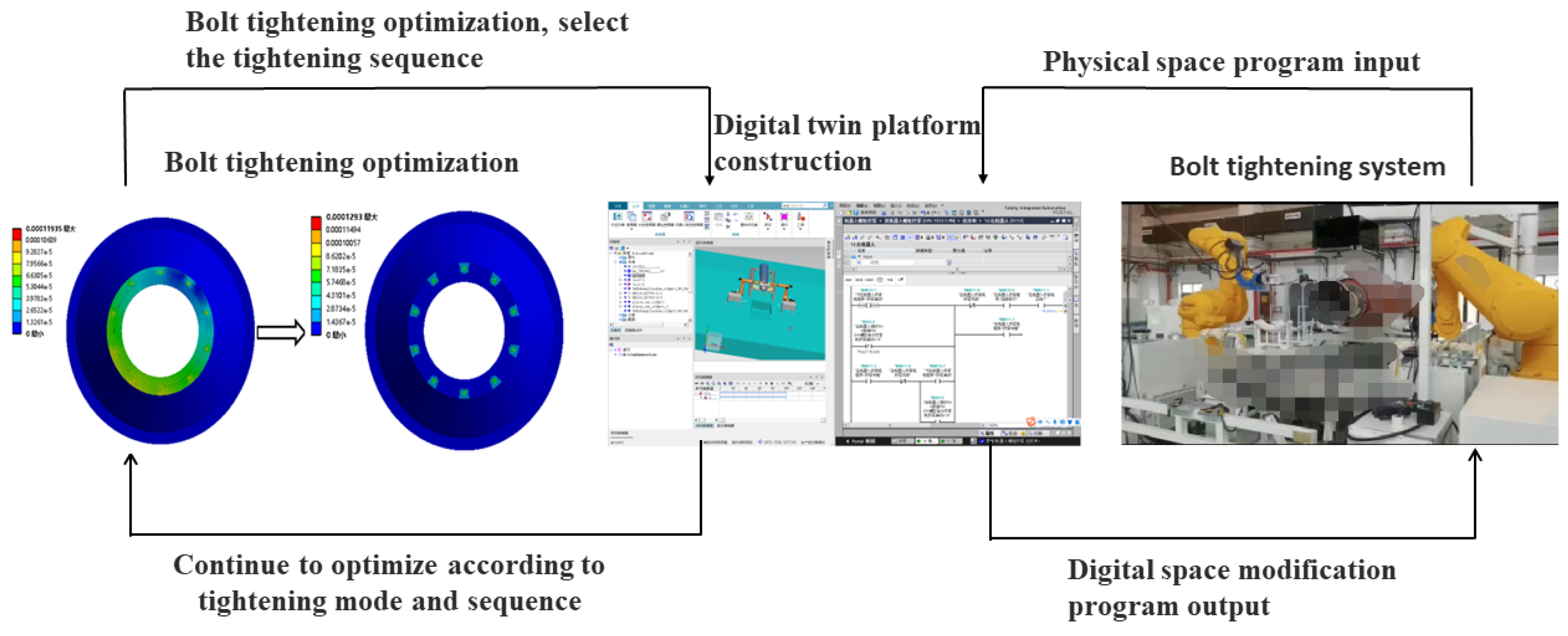
Considering the low efficiency of aerospace engine bolt tightening and the large deformation of the engine after tightening, bolt tightening is optimized based on digital twin flexible assembly, as shown in
Figure 1. Based on the bolt simulation optimization, the stress and deformation of the engine during the tightening process are reduced and evenly distributed. Bolt tightening efficiency and tightening process safety improve through digital twin platform. Real-time communication between physical space and digital space transmits robot trajectories and offline programs from digital space to physical space.
In
Section 2, a flexible bolt tightening mechanism is designed to be suitable for bolt tightening tasks on various types of engines. The maximum error between the digital space and the physical space is the gap caused by the different axis between the areospace engine cabin and the tightened surface. Errors are eliminated based on benchmark conversion method. In
Section 3, the bolt tightening sequence is determined by bolt tightening optimization. There is only deformation near the bolt hole position on the nozzle after optimization, and almost no deformation occurs in other positions. The maximum stress on the engine is reduced, and the residual pre-tightening force is more uniform. In
Section 4, the bolt tightening system is digitally modeled. In the experiment, visual real-time monitoring of aerospace engine bolt tightening process is applied. The physical space data are transmitted back to the digital space. In the research, the bolt tightening system completes the bolt tightening work of the aerospace engine by means of automation and digitization. Using conclusions drawn from bolt tightening optimization
Section 3, the article uses two robots to tighten the engine bolts simultaneously, as shown in
Figure 2.
3. Tightening Sequence Optimization
When a bolt is tightened first, the tightened surface of the engine will elastically deform. After the adjacent bolts are tightened, the preload force of the initially tightened bolts will be reduced due to elastic deformation. During the bolt tightening process of an aerospace engine, the large deformation of the engine surface and the large change in stress are unacceptable. To reduce the influence of elastic interaction, the bolt tightening sequence is optimized.
Different tightening sequences produce different results due to elastic interactions [
15]. In the selection of the tightening sequence, the goal is to have a uniform final load (at the end of tightening) under the same conditions as the initial load (at the beginning of tightening). Currently known tightening sequence optimization methods include Elastic Interaction Coefficient Method (EICM) [
16] and Inverse Sequence Method (ISM) [
17]. The EICM method is based on an assumed linear relationship between the load change of the tightened bolt and the final preload. This relationship is represented by a matrix of elastic interaction coefficients. The matrix varies with different tightening methods, and the detailed explanation of the elastic interaction matrix can be obtained by referring to [
18]. The ISM method is based on analyzing the loosening sequence from the final state of bolt loading back to the initial loosened state. Starting from a final state where each bolt has reached a certain preload, we loosen the bolts completely one by one in reverse order. This method can only be used for one optimized single tightening, since unloading to the target value of each bolt in each pass is a difficult task to achieve in practice, it cannot be used for optimizing multiple passes. Therefore, the EICM method is selected to optimize the tightening sequence in this paper.
The relationship between the initial load and the final load of the bolt in different sequences is as follows:
In the Formula (
1),
is the final load,
is the initial load,
is the elastic interaction matrix. In a system composed of n bolts, Formula (
1) can be expressed as the following Formula (
2):
where
is the final load of the bolt
k and
is the initial load of the bolt
k. Taking the first row of Formula (2) as an example, the final load of the first bolt is shown in Formula (
3):
There are 44 bolt holes in the cabin section of a certain type of aerospace engine, which are distributed symmetrically around the circumference. For ease of understanding, it is simplified to 10 bolt holes. 10 bolt holes are annularly distributed, and the structure is symmetrical. Different sequences are chosen for the simulation, and the most suitable sequence is chosen to be applied in this study.
The pre-tightening force of the bolt cannot exceed 80 percent of the material yield limit, and generally 60–70 percent is used in the calculation. Therefore, the pre-tightening force [
19] of bolts is calculated as follows:
In the Formula (
4), F is the bolt preload,
is the yield limit,
A is the nominal stress area, the bolt parameters selected in the experiment are shown in
Table 1:
Substitute the parameters into formula (4) to obtain F = 94,200–109,900 N, and the bolt pre-tightening force is set to 100,000 N. A finite element model for simulating the tightening sequence of aerospace engine bolts is established by ANSYS Workbench, and the optimization of the tightening sequence of aerospace engine bolts is carried out based on the finite element model. The material of nozzle, combustion chamber shell and bolt are all high strength steel, Young’s modulus is 209 GPa at room temperature, Poisson’s ratio is 0.29, and the interior of engine is non-metal material. When the bolt is tightenened, the surface of nozzle and combustor will appear large deformation and stress, and the effect on the rest of the nozzle and combustor is almost negligible. Therefore, the stress and deformation of nozzle and combustor surface are only considered when the bolt is tightened. The aerospace engine finite element simulation model is shown in
Figure 8.
To improve the accuracy of the calculation, the mesh on the contact surface is subdivided. Because the shape of the space engine is irregular, it cannot be generated by sweep or multizone method, so the tetrahedrons method is used. A total of 711,694 nodes and 446,765 elements are generated by refining the dimensions of the bolts and the tightened surface elements and roughening the grid of the fixed support (bottom surface) , as shown in
Figure 9. The lower surface of the bolt head is arranged in “Non-separation” contact with the upper surface of the nozzle. The contact type between the screw and the bolt hole is set to “Binding” contact. The type of contact between nozzle and combustor is set to “Frictional” contact with a friction factor of 0.2. To improve the convergence of the calculation, the contact behavior mode is set to symmetrical contact in the simulation. In addition, Augment Lagrange algorithm is used as contact formula in advanced settings to solve the problem of mutual penetration between contact surfaces. The weak spring is used to avoid the large displacement of the rigid body in the simulation results.
The bolt tightening sequence can be controlled by setting sub-steps in Ansys. One robot is used to tighten the aerospace engine in a given order, 60 force loads are set in finite element software Ansys. In the selection of tightening sequence, based on previous studies [
12,
20,
21], divide the bolt tightening sequence into sequencce tightening (1-2-3-4-5-6-7-8-9-10), interval tightening (1-3-5-7-9-2-4-6-8-10), diagonal tightening (1-6-2-7-3-8-4-9-5-10). The preload force loading mode is shown in the left part of
Figure 10, the engine deformation and its stress corresponding to the given sequence are shown in
Figure 10.
The image above shows the range of distortion caused by tightening the space engine in different order. The deformation amount and deformation trend of the aerospace engine of the above three order is shown in
Figure 11.
In the figure, the step means sub-steps. It can be seen from
Figure 10 that most of the engine cabin section deforms according to the above three sequences, and the stress value of the cabin section is relatively large. As shown in
Figure 11, the three sequences’ tightening of the space engine causes the large engine deformation, reaching 0.34 mm, 0.28 mm, and 0.22 mm. Furthermore, the deformation is not uniform, which is harmful to the aerospace engine. Therefore, the above three tightening sequences are not ideal tightening sequences.
As described in the previous paper, the pre-tightening force of previously tightened bolts is reduced due to the effect of elastic interaction. Therefore, the ideal tightening method is to pre-tighten all bolts at the same joint simultaneously, to achieve the design pre-tightening force, but the cost is high and it cannot be applied to other types of aerospace engines. Therefore, this paper first proposes that multiple robots tighten the aerospace engine at the same time to reduce the influence of elastic deformation. More than one robot is used to tighten the aerospace engine, as shown in
Figure 12. It can be seen from
Figure 12 that when three robots are used, there is not enough space for the robots to operate, and interference is easy to occur. It is easy to conclude that this result is also true for more than three robots. Therefore, two robots were finally designed to optimize tightening at the same time.
The design uses two robots to simultaneously tighten the aerospace engine with the same bolt preload. A total of 30 steps of force loading are set in the experiment. The sequence tightening, interval tightening, and diagonal tightening are set. The preload force loading mode is shown in the left part of
Figure 13, the stress and deformation corresponding to different orders are shown in the right part of
Figure 13. The deformation amount and deformation trend of the aerospace engine is shown in
Figure 14.
As shown in
Figure 13 and
Figure 14, the overall deformation of the two robots tightening the engine sections diagonally at the same time is the minimum, and the maximum deformation is about 0.05 mm, and the deformation is uniform and concentrated. According to the stress diagram, the overall maximum stress of the two robots tightening diagonally at the same time is 516 MPa, and the force is stable during the entire tightening process without sudden change.
As shown in
Figure 15, the maximum stress of the entire aerospace engine
is 1965.3 MPa before optimization. After optimization, the maximum stress of the engine
is 1846.5 MPa.
In the Formula (
5),
is the optimization percentage.
According to the simulation optimization results, the tightening sequence of this study is chosen as two robots simultaneously tighten the bolts diagonally. Applied to this study, one of the two robots tightens on the black wire, and the other tightens on the blue wire, the tightening sequence is (1,23)→(22,44)→(2,24)→(21,43)……. The tightening sequence of the three types of engines is shown in
Figure 16.
The two robots tighten the bolts of the aerospace engine diagonally at the same time, and the relationship between the initial load and the final load shown in Formulas (
1) and (
2) are expressed as the following Formulas (
6)–(
8):
In matrix
A, the bolts that have been tightened have no effect on the subsequent tightening of bolts, so their coefficients in the matrix are zero. The elastic interaction coefficient
Ai,j can be found by measuring the load of the tightened bolt at each tightening in a finite element model or in a test bench. In general, the elastic interaction coefficient is negative, because the change in load is usually a loss. Then, if matrix
A is known, the tightening loads
that will provide a uniform final load distribution
following a given assembly pattern can be calculated using the Formula (
9).
ECIM assumes that the initial load is linearly related to the final load through matrix A, so the method is theoretically only applicable to linear systems. When the system is nonlinear, each load in the matrix A is no longer constant, and the matrix A can be obtained by multiple calculations.
4. Establishment of the Digital Twin System of the Tightening Mechanism
A complete digital twin system includes physical layer, data layer, model layer, function layer and ability layer, which correspond to the five elements of digital twin—physical objects, object data, dynamic models, functional modules, and application capabilities.
According to the physical space, the 3D bolt tightening digital scene is laid out. The parts and resources as well as coordinate system and so on of the bolt tightening system are defined. The digital twin of the bolt tightening system is built. The tightening robot chooses the KUKA six-degrees-of-freedom robot KR210, which itself has six degrees of freedom, plus the rest of the robot’s movable parts, a total of nine joints and connecting rods are created. In the initial stage, the virtual debugging of the bolt tightening system is carried out by the use of the digital space model, and the problems existing in the system are detected, such as the incorrect placement of the parts causing the robot to exceed the measuring range, the relative position error between the nozzle and the chamber of the aerospace engine results in poor tightening effect. Then the digital space and the physical space are interacted in the production line mode. The physical space and the digital space realize data interaction through PLC and six-dimensional force sensor. The PLC controls the motion of the robot, and the six-dimensional force sensor transmits the tightening torque of the robot. The input and output signals of the bolt tightening system are created in digital space and add signals in the logic behavior editor. The operation is established and the parameters and constants of the operation are defined. PLC communicates with the digital space tightening system through the OPC communication protocol. Operations are built to complete virtual commission of digital space. Virtual commission aims to discover and solve problems in the assembly process of bolt tightening system in advance. The robot assembly path is planned using the quintic polynomial interpolation method in MATLAB, and the path is communicated to the digital space through OPC DA.
Digital space feedback the in-position signal, position signal, sensor signal, speed signal and so on of the bolt tightening robot to the physical space. Interference and error prediction in the tightening process can also be achieved in the digital space. Through the interaction between digital space and physical space, problems in physical space, just like problems with the PLC program, result in an incorrect tightening sequence being corrected. The rationality of physical space and digital space are verified through data interaction. At last, offline robot programs are generated in digital space. Compared with traditional teaching programming, offline programming omits tedious procedures. Therefore, it improves assembly efficiency. The digital twin of the aerospace engine bolt tightening system is shown in
Figure 17.
The physical layer refers to the aerospace engine bolt tightening system. The data layer refers to the PLC and the six-degree-of-freedom sensor. The communication between the digital space and the physical space is realized through them and the OPC communication interface. The model layer refers to the digital space model in process simulations. The operation precision of the model reaches 0.1 mm/m in the digital space, which ensures that the robot can complete the task according to the setting. The function layer refers that when the aerospace engine is tightened in the digital space, the problems such as interference and collision can be predicted and detected. The last is the ability Layer. Through the digital space bolt tightening system, the final target is to complete off-line programming of the robot, so as to improve the efficiency of aerospace engine tightening.
When the aerospace engine is tightened in the physical space, a visual camera is used to monitor the tightening process in real time, and the data are transmitted back to the digital space in real time, as shown in
Figure 18.
The torque of the tightening machine is monitoring real-time in the tightening process. We compared the torque with a specific value (different values for different types of bolts) (320 N.m in 44 bolts type). After the tightening machine has tightened a given number of turns, it is detected whether the torque reaches the given value. If the given value is reached, the judgment is successful, otherwise the judgment fails. The bolt tightening process is monitored real-time based on vision. The bolt tightening position is detected by visual camera and digital twin software-process simulations. Combined with process simulations, we can judge whether there is a collision during the tightening process.
The digital twin of the tightening system verifies the path and operational safety of the robot. It ensures that the system performs as expected, and greatly reduces the time for tightening and debugging the aerospace engine work system in the physical space.
5. Experiments
It is concluded from
Section 3 that two robots are used to tighten the aerospace engine diagonally. The tightening torque is obtained by Formula (
10).
In the formula, T is the tightening torque, K is the torque coefficient, D is the nominal diameter of the bolt, and F is the preload. In this paper, the engine with 44 bolt holes needs to tighten the M16 bolt, D = 16 mm. There is no lubrication on the surface of bolt, K takes 0.2.
In summary, the tightening torque can be calculated as 320 N·m.
The robot tightening process during the experiment is shown in
Figure 19.
Figure 20 is an experimental diagram of a robot tightening a bolt in a physical space.
According to the above method, for the structure of the three types of nozzles at present, corresponding tightening sleeves are designed to realize the automatic picking and tightening of bolts to the greatest extent.
Table 2 is the accounting table of the number of automatic tightening bolts for the three types of aerospace engine.
Three types of space engines are tightened using the digital twin-based flexible tightening method proposed in this study. Using different types of bolts to tighten different shapes of aerospace engines, the success rate is 100 percent. It takes about 3 h to tighten the type 1 engine bolts using the traditional method, but only 12 min and 23 s with the proposed method. For type 2 and 3, it takes about 2 h and 20 min and 1 h and 50 min, respectively, before optimization, and only 9 min and 17 s and 6 min and 38 s after optimization.
Based on ultrasonic bolt pre-tightening force measurement method, the residual pretightening force values of three types of aerospace engine before and after process planning are measured, respectively. The ultrasonic tester for bolt pretension is the equipment used to measure the residual tightening force. Because the temperature change will produce the big influence to the experimental result, it is set to be constant in the experiment. The machine is coupled to one end of the bolt. It launches ultrasonic pulses in the bolt. Each pulse travels to the other end of the bolt where it is reflected. The reflected pulse travels back to the transducer where it is electronically received or sensed. The instrument measures round trip pulse travel time and converts it to ultrasonic length. The unloaded ultrasonic length reading is taken on the bolt before any load is applied. After loading the bolt, the loaded ultrasonic length reading is taken. The ultrasonic stretch is multiplied by appropriate factors in the instrument to indicate the residual tightening force. Furthermore, the results are shown in
Figure 21.
It can be seen from
Figure 21 that the residual pre-tightening force of a robot tightens sequentially is small. After using other two sequence, the value of bolt residual pre-tightening force improves but not even. By using two robots to tighten at the same time, the residual pre-tightening force of the space engine has been qualitatively enhanced. Until we use two robots tighten diagonally, the value of bolt residual pre-tightening force is high and even.
The application of digital twinning in the process of aerospace engine bolt tightening improves tightening efficiency and enhances the safety of tightening process. The optimization of tightening process reduces the difficulty of bolt tightening and engine deformation. Then it can be applied to the bolt tightening process of multi-type in small and medium batches of aerospace engines.

 ,
, 


