Article

Active Control Method for Rotor Eccentric Vibration of High-Speed Motor Based on Least Squares Support Vector Machine

1
Institute of Plasma Physics Chinese Academy of Sciences, Hefei Institutes of Physical Science, Chinese Academy of Sciences, Hefei 230031, China
2
Science Island Branch, University of Science and Technology of China, Hefei 230026, China
*
Author to whom correspondence should be addressed.
Machines 2022, 10(11), 1094; https://doi.org/10.3390/machines10111094
Submission received: 9 October 2022 / Revised: 14 November 2022 / Accepted: 14 November 2022 / Published: 18 November 2022
(This article belongs to the Section Machines Testing and Maintenance)

Abstract

:
Aiming at the problems of large active control errors and long control times in the active control method for high-speed motor rotor eccentric vibration, an active control method for high-speed motor rotor eccentric vibration based on a least squares support vector machine was proposed. Firstly, the overall structure of the system and its high-speed rotor were designed. Secondly, by calculating the centrifugal force of the eccentric rotor, the vibration of the relative phase of the rotor position, and the width of the air gap between the rotor and the stator, a mathematical model of the eccentric vibration of the high-speed motor rotor was established. Then, the basic principle of the least squares support vector machine was analyzed, and the control parameters of the eccentric vibration of the high-speed motor rotor were set and filtered. Finally, an active control model of high-speed motor rotor eccentric vibration was constructed, and the optimal solution of the model was obtained by regression algorithm. The experimental results show that the method is effective for the active control of high-speed motor rotor eccentric vibration, the control effect is consistent with the ideal effect, and the control time is short—the longest is only 0.13 s.

1. Introduction

With the rapid development of China’s industrial production technology, motors have been widely used in a variety of machinery production equipment and industrial fields [1]. In order to comply with the development of technology, high-speed motors have also been developed in operation, which have the advantages of small size and high power density [2]. Eliminating transmission and other traditional mechanical growth devices can improve system transmission efficiency, reduce system noise, and meet the needs of current low-carbon economic development [3]. With the wide application of high-speed motors, the requirements for cleanliness, working life, rated dynamic load, and controllability of the motor rotors are becoming greater and greater [4]. However, due to the limitations of the working principle and mechanical structure of traditional motor rotors, it is difficult to meet the application requirements of special production equipment due to the problems of lubricating oil pollution, limited supporting load, and difficult heat dissipation [5]. Due to the deviation in the vibration process of the high-speed motor rotor, there is a certain deviation in the production process, which affects work efficiency. Therefore, the control of the eccentric vibration of high-speed motor rotors is very important [6]. At present, many control methods have been proposed by relevant researchers, and some research results have been achieved.
Reference [7] designed a fast diagnosis method for surface-mounted permanent magnet motor rotor eccentricity faults and realized motor rotor eccentricity control by this method. The expression of the radial electromagnetic force wave (refw) when the rotor was not eccentric was derived by an analytical method. By introducing correction coefficients of static and dynamic eccentricity, the analytical expressions of the radial electromagnetic force wave under static and dynamic eccentricity of the rotor were derived. The results were analyzed and verified by the finite element method. The feasibility of this method was verified by the wireless vibration test. The eccentricity correction coefficient determined by this method had a certain accuracy, but there were few external environmental factors considered in the calculation process, which led to a poor effect on the eccentricity control of the motor rotor. Eccentric static and dynamic eccentric belong to two air gap eccentric cases; static eccentricity refers to the heart upon a stator and rotor of uneven static, while dynamic eccentricity is due to a shaft bending or an uneven rotor and shaft dynamic produced by a different heart, which can cause the electromagnetic vibration characteristics of the vibration to not be identical. Among them, the static eccentricity and dynamic eccentricity of the rotor’s center of rotation and the stator center do not coincide, but in the static eccentricity of the center of rotation, the rotor’s center of rotation is unchanged, and in the center of dynamic eccentricity, the rotor’s center of rotation is around the center of rotation. The two different eccentric ways of the electronic rotor will also have a different influence on its operating power. In reference [8], an analytical calculation method for the eccentric no-load air gap magnetic field of the rotor of a permanent magnet synchronous motor was proposed. An analytical calculation method based on equivalent transformation was proposed to calculate the magnetic field of the rotor eccentricity spacetime carrier air gap. Based on the principle of equivalent transformation, the residual magnetic of a rotor eccentric motor model was transformed. The specific analytical expressions of the vector magnetic potential in each subdomain of the equivalent motor model were given according to two different cases of rotor static and dynamic eccentricity combined with the subdomain method. The motor no-load air gap magnetic field under rotor eccentricity was calculated. The accuracy of eccentric vibration analysis by this method was high, but there were some errors in the parameter determination in the control process. Reference [9] proposed a torque ripple suppression method for an external rotor permanent magnet motor based on stator crown eccentricity. The structure of stator crown eccentricity was studied to suppress the torque fluctuation of the external rotor permanent magnet synchronous motor for a 12-slot 10-pole fan. Based on the idea of unequal air gap length, the corresponding air gap length of the middle part of the stator crown arc of the initial structure was kept unchanged. Finite element analysis software was used to simulate and analyze the external rotor permanent magnet synchronous motor with a stator crown eccentricity structure. The torque fluctuation coefficient of the motor under different eccentricities was studied, and the influence of crown eccentricity on output torque, cogulation torque, and the harmonic distortion rate of the air gap magnetic field was analyzed. It was found that the eccentric structure of the stator crown can effectively suppress the output torque fluctuation and cogulation torque amplitude and improve the air gap flux density waveform. However, this method is complicated, inefficient, and time-consuming.
In order to solve the problems of large active control errors and long control times in the above methods, an active control method for the rotor eccentric vibration of a high-speed motor based on a least squares support vector machine is proposed in this paper. This method determines the key factors affecting the eccentric displacement of a high-speed motor rotor by establishing a mathematical model of the eccentric vibration of the high-speed motor rotor. Then, based on the parameters of the high-speed motor rotor active control, an active control model is established to realize the active control of the high-speed motor rotor. Finally, the optimal solution of the model is obtained by using a regression algorithm, which improves the accuracy of the high-speed motor rotor eccentric vibration trajectory control and reduces the control error value. It also shortens the control time and is expected to provide a reliable value reference and help for the future development and application of high-speed motors. The key technical route of this method of research is as follows:
(1) The overall structure of the water-cooled high-speed permanent magnet synchronous motor system and its high-speed rotor structure is designed. The design parameters of the high-speed motor rotor are clarified, and its performance is basically analyzed, which lays the foundation for the active control of the eccentric vibration of the high-speed motor rotor.
(2) Based on the determined rotor structure of high-speed operation, a mathematical model of the rotor eccentric vibration of the high-speed motor is constructed by calculating the centrifugal force on the eccentric rotor, the vibration of the rotor position opposite phase, and the width of air gap between the rotor and the stator.
(3) Based on the analysis of the basic principle of a least squares support vector machine, the control parameters of the high-speed motor rotor eccentric vibration are set and filtered. Therefore, an active control model of high-speed motor rotor eccentric vibration is constructed, the optimal solution of the model is obtained by a regression algorithm, and the active control method is studied.
(4) The experimental sample high-speed motor and its application and experimental environment are clarified. The control situation and control time cost of the eccentric vibration track of the sample high-speed motor rotor under the three methods are explored by comparing the two methods to verify the effectiveness and application efficiency of the proposed method.
(5) Through the analysis of the experimental results, it is confirmed that the method is effective for the active control of the eccentric vibration of the high-speed motor rotor, and the whole control process consumes less time. Based on this and looking into the future research direction, more parameters that may affect the rotor rotation of the high-speed motor will be studied to expand the universality of the research results in this paper.

2. Active Control of Rotor Eccentric Vibration of High-Speed Motor Based on Least Squares Support Vector Machine

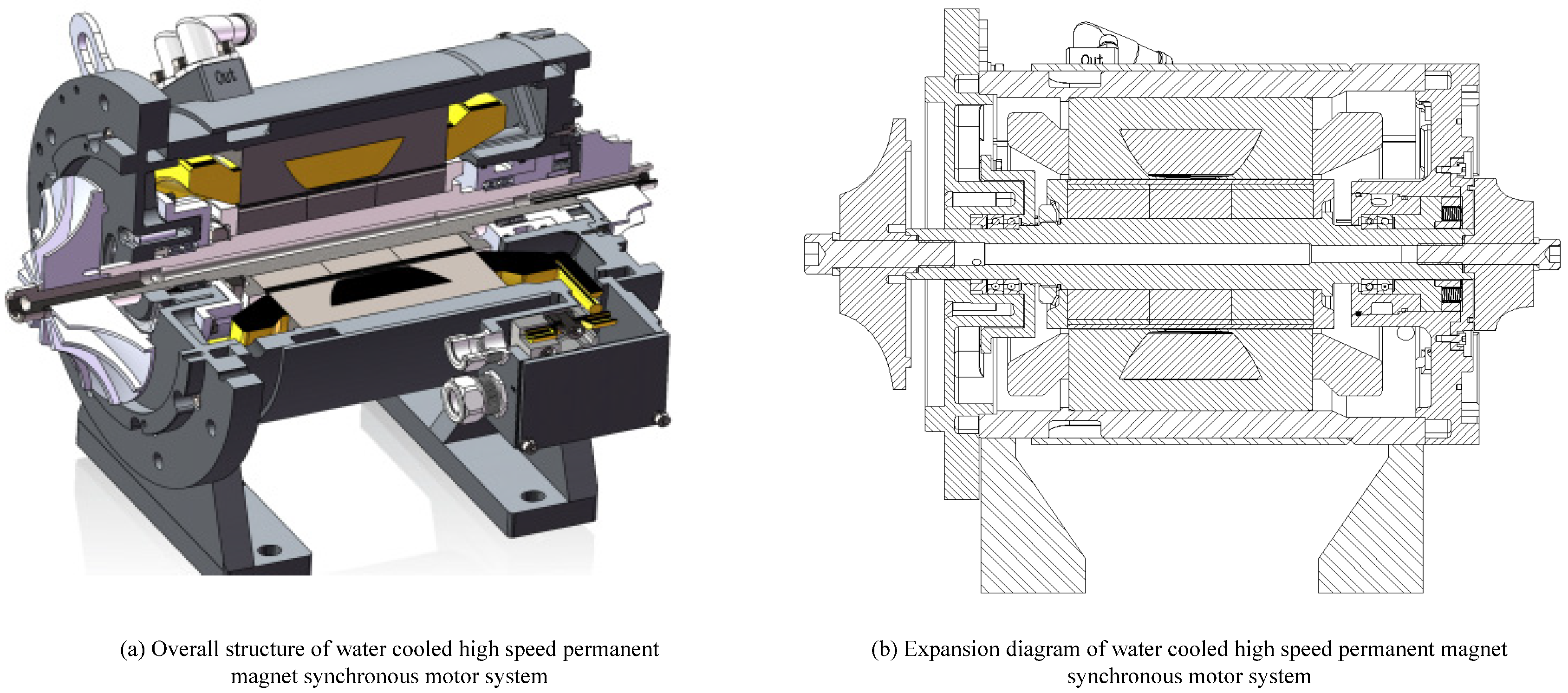
2.1. Structure and Composition Data of High-Speed Motor

In order to study the active control method for the rotor eccentric vibration of a high-speed motor, a high-speed motor is designed in this paper. The overall structure of the water-cooled high-speed permanent magnet synchronous motor system is shown in Figure 1.
The main components of the high-speed permanent magnet synchronous motor are: stator, stator winding, rotor, and permanent magnet. The stator is composed of a three-phase winding and armature iron core, the number of winding turns is 264, and the rotor is composed of a permanent magnet, rotating shaft, and magnetic conductor. When the current flows through the stator, a magnetomotive force of the same shape will be generated in the gap between the stator and the rotor. The interaction between the stator flux and the rotor flux makes the permanent magnet synchronous. The specific composition data are shown in Table 1.

2.2. Mathematical Model of Rotor Eccentric Vibration of High-Speed Motor

The rotor is an important part of the machine in the high-speed motor. The running state and presentation state of the part directly affect the normal operation of the high-speed motor. In order to analyze the rotor eccentric vibration of the high-speed motor, it is necessary to build a mathematical model of the rotor eccentric vibration of the high-speed motor [10]. The rotor used in this paper is a shafting rotor, and its structure is shown in Figure 2.
The structure of the high-speed motor shafting rotor is a back-to-back structure, with one end a booster and one end an expander. The specific performance data are shown in Table 2.
In the high-speed motor shafting rotor system, due to the asymmetric structure of the rotor, the quality defects of the raw materials, machining, and assembly errors, and other reasons, the unbalanced distribution of the rotor mass leads to the formation of rotor mass eccentricity. The rotor is subjected to the combined action of unbalanced magnetic tension and centrifugal force, resulting in radial vibration. The centrifugal force on the eccentric rotor is directly proportional to the square of the speed. When the speed increases to a certain extent, the amplitude of the radial vibration of the rotor will increase sharply. Due to the elastic support, part of the vibration force will be transmitted to the base, causing the system to vibrate. Moreover, the width of the air gap between the stator and rotor is limited, and the violent vibration of the rotor exceeding the air gap will even lead to damage to the system [11].
The mass imbalance of the rotor is divided into static imbalance and dynamic imbalance. The static imbalance of the rotor is shown in Figure 3. The unbalanced mass of the rotor is distributed on one side of the rotor. The resultant force of the centrifugal force generated by the eccentric mass at both ends can be equivalent to a force passing through the center of mass C, and the inertia axis of the rotor is parallel to the geometric centerline of the rotor [12,13]. The static unbalance of the rotor produces the same phase vibration at the left and right radial bearings.
The dynamic unbalance of the rotor is shown in Figure 4. The unbalanced mass of the rotor is distributed on both sides of the rotor. The centrifugal force generated by the additional eccentric mass at both ends of the rotor is in the opposite direction. The inertial principal axis of the rotor intersects the geometric centerline and has an e angle. The dynamic imbalance of the rotor produces antiphase vibration at the left and right radial rotor positions [14].
The radial magnetic suspension bearing stator and rotor cross-section to two contained solid circles, due to the uneven distribution of mass, produces an eccentricity size e, 0 points is the rotor centroid, and C is the rotor centroid. M is any point on the rotor section circle when the rotor rotates around its inertial axis, namely the centroid; the M point is l 1 , and the centroid zero track is l 2 . According to the analysis, when the rotor rotates around the inertial main axis, the width of the air gap between the rotor and the stator changes periodically with the rotor rotation at the same frequency as the rotational speed, as shown in Figure 5.
When the rotor has a high-speed rotating motion with eccentric mass, the centrifugal inertia force f r borne by the rotor is:
f r = m ω 2 e c o s ω t + φ 0
In the formula, m represents the rotor mass, ω is the rotational angular velocity, e is the rotor eccentricity, and φ 0 is the initial phase.
During the coordinate operation of the rotor, when the rotor exists statically in the Z direction, the single degree of freedom rotor motion system has an eccentric displacement X , which is affected by the external control electromagnetic force
X = x x
Formula (2) represents the eccentric displacement at the relative equilibrium position, where x represents the position of the rotor in the coordinates, x represents the equilibrium position of the rotor in the static existence, and the state is converted to obtain:
F = F 2 F 1 = k [   i 0 + i x 2 x o N 2   i 0 i x 2 x o + X 2 ]
Among them, i 0 represents the guide rate in rotation, i x represents the pole area of the electromagnet, N represents the number of electric coil turns of the radial rotor bearings, and x o represents the initial state value of the rotor.
When X = 0 ,     i x = 0 , Taylor expansion is carried out for the motion state around the rotor of the high-speed motor, and the high-order infinitesimal quantity is removed. The linearized model of the small deviation range of the rotor operation eccentricity is obtained as follows:
F = K x X + K i x K x = i 0 A 0 N i 0 2 x 0 3 K i x = i 0 A 0 N i 0 2 x 0 2
In the formula, K represents the current stiffness and K x represents the displacement stiffness of the rotor, N represents the shaft torque value of the rotor, and A 0 represents the cross-sectional area of a single rotor.
Since the direction of the rotor force is the same in the X direction, at this point, K x is a value greater than 0. In this case, the rotor displacement actually has a certain negative stiffness regarded as a linear relation [15] controlling the current. The eccentric shift model at this time can be:
G s = X s L s = k x m s 2 k x
When the high-speed motor operates rapidly, the combined force of the rotor is:
F = k x 0 + k i 0
The centrifugal inertial force due to mass bias is 0. Then, the force is:
m x = F m g
Among these, m represents the rotor displacement acceleration, and g represents the own mass of the rotor.
According to the above calculation, the mathematical model of the high-speed motor rotor can be expressed as:
m x i = k u d + f r
Among these, k u represents the rotor offset centerline distance, and d represents the gas gap spacing between the rapidly rotating rotor surface and the stator. It can be seen that the fast-speed motor rotor eccentric displacement is more affected by centrifugal inertia force, bearing electromagnetic force, and rotor gravity.

2.3. Active Control of High-Speed Motor Based on Least Squares Support Vector Machine

Based on the mathematical model of the rotor eccentric vibration of the high-speed motor determined by the above analysis, the key influencing factors affecting its eccentric displacement are determined. In order to realize the active control of the rotor eccentric vibration of the high-speed motor, a least squares support vector machine is introduced to study the active control [16].
The least squares support vector machine is an online learning algorithm with a time window. The algorithm can be decomposed into a learning process of adding a sample, and the learning process of the research object can be eliminated by the algorithm. Its basic original is:
Set the phalanx studied by this algorithm to A to represent it as:
A = A 11 A 12 A 21 A 22
If the A 11 is reversible, the B = A 22 A 21 A 11 1 A 12 is also reversible, as follows:
A 11 A 12 A 21 A 22 1 = A 11 1 + A 11 1 A 12 B 1 A 21 A 22
According to the reversibility of the least squares support vector machine, the research object is incrementally learned to complete the application of the algorithm. Assuming that there are samples in the research object, the newly added sample data sequence can be expressed as
H l + 1 = Q l + 1 + C 1 I = H 1 V l + 1 V l + 1 T V l + 1
In the formula, V l + 1 T represents the original sample data sequence.
Based on the basic principle of the least squares support vector machine, the algorithm is applied to the active control of eccentric rotor vibration of the high-speed motor. The high-speed motor rotor mass eccentric vibration displacement signal is a regular periodic sine disturbance signal. In the rotor displacement signal model, when the rotor is in mass bias, the random displacement signal is expressed as γ a , the eccentric vibration displacement signal with the same speed is γ s , the horizontal y direction and vertical x direction bearing rotor radial displacement is γ, and the eccentric rotor radial displacement expression may be expressed as:
γ = γ a + γ s
where, the mass eccentricity sinusoidal perturbation y can be expressed as:
γ s = A s i n ω t + φ 0
Among them, A represents the rotor displacement signal method, ω t represents the rotor rotation angle frequency, and φ 0 represents the initial rotation phase.
According to the above analysis, since the disturbance caused by the eccentric vibration of the rotor mass is in the form of a sinusoidal signal, some characteristics of the disturbance signal are known a priori, and adaptive LMS filtering can be carried out for the sinusoidal disturbance of rotor.
Then, x k = A s i n 2 π f 0 k is the input signal for the algorithm; c o s 2 π f 0 k is the algorithm weight vector, with the optimal weights given by the algorithm control program; f 0 is the algorithm reference input signal frequency, i.e., the rotor vibration signal frequency; and γ k is the desired signal of the algorithm and the input signal, a maglev rotor displacement signal containing an eccentric vibration signal component.
Based on the parameters of the active control of the high-speed motor rotor, the active control model is constructed to realize the active control of the high-speed motor rotor.
Assuming that the sample data for the control eccentricity parameters for the active control training are:
x k , y k k = 1 , 2 N
where x k R n represents the input data from the K training sample, and y k R n represents the output data when the active control model of the high-speed motor rotor polarization vibration is:
y x = w T φ x + b
Among these, w represents the weight vector, y k R n ,     b R n represents the offset, and φ x represents the kernel space mapping function.
The active control model of the rotor eccentric vibration of the high-speed motor constructed above can improve the control effect, but the nonlinearity of its motion affects the results of its control in different states. Therefore, it is necessary to solve the optimal solution for its control. In this paper, the optimal solution for the active control model of the rotor eccentric vibration of the high-speed motor is calculated with the help of a regression algorithm, that is
k = 1 N ε K 2 m i n J w , e = 1 2 w 2 + 1 2 σ S . T .   y k = w T φ x k + b + ε k , k = 1 , 2 , N
Among them, ε k represents the relaxation factor of the insensitive loss function, J represents the optimization objective function, and σ represents the regularization parameter.

3. Experimental Analysis

3.1. Design of Experimental Protocol

In order to verify the effectiveness of the designed method, an experimental analysis is carried out. The application environment of the sample high-speed motor in the experiment is shown in Table 3.
The specific experimental environment is shown in Figure 6.
Figure 6 mainly includes a displacement sensor, detection probe, interface circuit board, 75 kW permanent magnet synchronous motor, upper computer, dSPACE controller, two-level switch power amplifier, and noncontact eddy current displacement sensor. The displacement change in the rotor is detected by an eddy current displacement sensor.
According to the designed experimental environment, the rotor axis trajectory of the sample high-speed motor is extracted, and the speed of the sample high-speed motor is changed to 25,000 rpm. Its elliptical trajectory is dominated by power frequency rotations, which will produce a certain eccentric displacement after acceleration. The rotor axis trajectory of the sample high-speed motor is shown in Figure 7.

3.2. Experimental Result

In order to verify that the method in this paper can effectively control the rotor eccentric vibration of a high-speed motor, the methods in this paper, reference [7], and reference [8] are used to effectively control the rotor eccentric vibration track of the sample high-speed motor. The experimental results are shown in Figure 8.
By analyzing the experimental results in Figure 8, it can be seen that there are some differences in the control effects after the methods in this paper, in reference [7], and in reference [8] are used to effectively control the rotor eccentric vibration track of the sample high-speed motor. Among them, with the acceleration of the eccentric vibration speed of the sample high-speed motor rotor, the method in this paper can effectively control its running track, and the results are consistent with the ideal results. After the other two methods control the rotor eccentric vibration track of the sample high-speed motor, the eccentric position has a certain displacement, which cannot reasonably control its change. This is because this method analyzes the structure and composition data of the high-speed motor in detail before the eccentric control, constructs the mathematical model according to the key parameters affecting eccentric displacement, and obtains the optimal solution for the control, which improves the accuracy of the rotor eccentric vibration trajectory control of the high-speed motor and reduces the error value of the control.
In order to further verify the effectiveness of this method, the time cost of the active control of the rotor eccentric vibration trajectory of the sample high-speed motor is experimentally analyzed by using this method, reference [7], and reference [8]. The experimental results are shown in Table 4.
By analyzing the experimental data in Table 3, it can be seen that there are some differences in the time cost of the active control of the rotor eccentric vibration trajectory of the sample high-speed motor by using the methods in this paper, in reference [7], and in reference [8]. Among them, when the rotor speed is 35,000 rpm, the time cost of the eccentric control of this method is 0.12 s, and the time cost of the active control of the rotor eccentric vibration trajectory of the sample high-speed motor by the methods in reference [7] and reference [8] are 0.28 s and 0.36 s, respectively; When the rotor speed is 50,000 rpm, the time cost of the eccentric control of this method is 0.11s, and the time cost of the active control of the rotor eccentric vibration trajectory of the sample high-speed motor by reference [7] and reference [8] are 0.40s and 0.46s, respectively. In contrast, the control time overhead of this method is short and has a certain work efficiency.

4. Conclusions

In order to improve the effectiveness of the active control method for the rotor eccentric vibration of a high-speed motor, an active control method for the rotor eccentric vibration of a high-speed motor based on a least squares support vector machine was proposed in this paper. The overall structure of a water-cooled high-speed permanent magnet synchronous motor system and its high-speed rotor structure was designed, which lays the foundation for the active control of the rotor eccentric vibration of a high-speed motor. Based on the determined rotor structure of high-speed operation, a mathematical model of the rotor eccentric vibration of a high-speed motor was constructed by calculating the centrifugal force on the eccentric rotor, the vibration of the rotor position opposite phase, and the width of air gap between the rotor and the stator. The control parameters of the high-speed motor rotor eccentric vibration were set and filtered. On this basis, an active control model of the high-speed motor rotor eccentric vibration was constructed, and the optimal solution for the model was obtained with the help of a regression algorithm to complete the research into active control. The experimental results show that the method is effective for the active control of high-speed motor rotor eccentric vibration, the control effect is consistent with the ideal effect, and the control time is short, the longest being only 0.13 s. Although this method is feasible at this stage, there are still many deficiencies. In future research, more parameters affecting rotor rotation will be studied to improve the effectiveness of the method.

Author Contributions

Conceptualization, L.W. and M.Z.; Control method, L.W. and K.Y.; Experimental scheme design, L.W. and M.Z.; Data Management, K.Y.; Conclusion Analysis, L.W., M.Z. and K.Y.; Writing-First draft preparation, L.W.; Writing, reviewing and editing, M.Z. and K.Y. All authors have read and agreed to the published version of the manuscript.

Funding

This paper was funded by the Anhui Provincial Natural Science Foundation (Grant No. 1808085ME124) and the Comprehensive Research Facility for Fusion Technology Program of China (Contract No. 2018-000052-73-01-001228).

Data Availability Statement

The datasets used and/or analyzed during the current study are available from the corresponding author on reasonable request.

Acknowledgments

All authors have read and approved the manuscript for publication.

Conflicts of Interest

The authors declare no conflict of interest.

References

  1. Xiao, J.K.; Zheng, G.F.; Liu, P.X.; Lin, D.Q. Overview for the Development and Key Technologies of High Speed Motors. Electr. Drive 2020, 50, 3–915. [Google Scholar]
  2. Bao, X.C.; Wang, X.L.; Peng, X.H.; Yan, T.X.; Gao, Q.X. Rerview of key technologies for high-speed motor drive. Chin. J. Electr. Eng. 2022, 42, 6856–6870. [Google Scholar]
  3. Qin, W.J.; Zhao, F.; Dong, J.F.; Zhuo, L. Research onapplication of amorphous materials in high-speed motors for high-altitude aircraft. Micromotor 2021, 54, 104–109. [Google Scholar]
  4. Wang, X.P.; Yang, C.H.; Qu, C.Y. Electromagnetic analysis and parameter optimization of auxiliary magnetic barrier permanent magnet synchronous motor. Micromotor 2022, 55, 28–36. [Google Scholar]
  5. Du, W.; Sun, Y.G.; Tian, D.Z.; Gui, L. Online monitoring method for rotor demagnetization fault of permanent magnet synchronous machine based on new type of search coil. Power Autom. Equip. 2020, 40, 218–222. [Google Scholar]
  6. Gong, L.; Zhu, C.S. Simultaneous vibration suppression of rigid rotor of maglev high-speed motor based on four factor variable polarity control. Chin. J. Electr. Eng. 2021, 41, 1515–1524. [Google Scholar]
  7. Li, Q.F.; Huang, H.J.; Huang, S.R.; Li, L.H. Research on fast diagnosis of rotor eccentricity fault for surface-mounted permanent magnet motor. Electr. Mach. Control 2019, 23, 48–58+67. [Google Scholar]
  8. Ren, J.; Wang, X.H.; Zhao, W.L.; Xing, Z.Z. Open circuit magnetic field prediction in permanent magnet synchronous machine with rotor eccentricity. Electr. Mach. Control 2020, 24, 26–32. [Google Scholar]
  9. Du, X.B.; Huang, K.S.; Cai, L.M. Reducing torque ripple of external rotor permanent magnet motor based on structure of stator tooth eccentricity. Small Spec. Electr. Mach. 2019, 47, 21–24, 28. [Google Scholar]
  10. Ji, Y.; Sun, L.; Li, Y.; Li, J.; Liu, S.; Xie, X.; Xu, Y. Non-destructive classification of defective potatoes based on hyperspectral imaging and support vector machine. Infrared Phys. Technol. 2019, 99, 71–79. [Google Scholar] [CrossRef]
  11. Ma, C.; Gao, Y.; Degano, M.; Wang, Y.; Fang, J.; Gerada, C.; Zhou, S.; Mu, Y. Eccentric position diagnosis of static eccentricity fault of external rotor permanent magnet synchronous motor as an in-wheel motor. IET Electr. Power Appl. 2020, 14, 2263–2272. [Google Scholar] [CrossRef]
  12. Jacobellis, G.; Gandhi, F.; Floros, M. Using control redundancy for power and vibration reduction on a coaxial rotor helicopter at high speeds. J. Am. Helicopter Soc. 2019, 64, 1–13. [Google Scholar] [CrossRef]
  13. Dong, H.M.; Zhang, A.S.; Shu, H.; Zhang, C. Simultaneous identification method of rotor distributed unbalance and bearing characteristic parameters. J. Harbin Inst. Technol. 2022, 54, 128–135. [Google Scholar]
  14. Li, B.; Bu, W.S.; Chen, Y.P. Simulation compensation of rotor unbalance vibration of bearingless asynchronous motor. Comput. Simul. 2020, 37, 243–247. [Google Scholar]
  15. Nair, R.; Gopalaratnam, N. Stator flux based model reference adaptive observers for sensorless vector control and direct voltage control of doubly-fed induction generator. IEEE Trans. Ind. Appl. 2020, 56, 3776–3789. [Google Scholar] [CrossRef]
  16. Ji, L.; Ma, X.Q.; Chen, Z.M. Low frequency vibration mechanism for amb high-speed motor rotor systems and its compensation strategy. China Mech. Eng. 2022, 17, 2053–2060. [Google Scholar]
Figure 1. Overall structure of water-cooled high-speed permanent magnet synchronous motor system.
Machines 10 01094 g001
Figure 2. Structure diagramof high-speed motor rotor.
Machines 10 01094 g002
Figure 3. IN phase vibration of rotor at left and right radial bearings.
Machines 10 01094 g003
Figure 4. Case of the reverse phase vibration of the rotor at the left and right radial rotor position.
Machines 10 01094 g004
Figure 5. Periodic change in rotor rotation.
Machines 10 01094 g005
Figure 6. Experimental setup.
Machines 10 01094 g006
Figure 7. Normal operation track of rotor axis of sample high-speed motor.
Machines 10 01094 g007
Figure 8. Analysis of high-speed motor rotor eccentric vibration trajectory control results of different methods [7,8].
Machines 10 01094 g008
Table 1. Specific composition data of experimental high-speed motor.
CompositionData
CategoryWater-cooled high-speed permanent magnet synchronous motor
Rated value380 Vac, 96 Arms, 50 kW, 35,000 rpm
Rotor structureExternal diameter, 87.4 mm; axial, 140 mm;
2-pole surface paste, the permanent magnet under monopole is magnetized in parallel in three sections and wound with high-strength carbon fiber sheath
Stator structureExternal diameter, 185 mm; internal diameter, 89 mm;
axial, 140 mm
24-slot, 3-phase, double-layer, short-distance laminated winding
Main materialsCore 0.2 mm silicon steel sheet
Samarium cobalt permanent magnet
Spindle material 42CrMo
Motor applicationRefrigeration equipment with impeller at both ends
Table 2. Specific performance data of shafting rotor.
ProjectData
Entrance pressure at the booster end (bar)3.5
Export pressure at the booster end (bar)5.873
Supercharged end flow (g/s)1011
Biocharged end inlet temperature (°C)30
Charge outlet temperature (°C)100
Expansion-end inlet pressure (bar)5.773
Export pressure at the expansion end (bar)3.57
Expansion end flow (g/s)1011
Expansion-end inlet temperature (°C)−55.12
Export temperature at the expansion end (°C)−80
Table 3. Application environment of experimental high-speed motor.
ProjectData
Work environmentAtmospheric environment
Specific application purposeHang the turbine for the cooling application
Air intake atmospheric pressure3.5 bar
Exhaust atmospheric pressure5.7 bar
Rate of flow1.1 kg/s
Internal atmospheric pressure inside the motor6 bars
Compressor air inlet temperature35 °C
Compressor exhaust temperature100 °C
Table 4. Time cost of active control of rotor eccentric vibration trajectory of high-speed motor with different methods (s).
Rotor Speed (rpm)Eccentric Control Time Cost of this Paper Method(s)Eccentric Control Time Cost of Document [7] Method(s)Eccentric Control Time Cost of Document [8] Method(s)
25,0000.110.230.32
30,0000.120.250.34
35,0000.120.280.36
40,0000.130.310.42
45,0000.120.360.44
50,0000.110.400.46
Publisher’s Note: MDPI stays neutral with regard to jurisdictional claims in published maps and institutional affiliations.

