Abstract
Brushless direct current (BLDC) permanent magnet (PM) synchronous motors are in high demand for ventilator applications owing to their high speed, high efficiency, and other significant features. However, it has become an important problem in eddy current loss calculations with high-speed motors, which leads to low motor (ventilator) life and PM demagnetization. This paper focuses on the eddy current loss calculation and the structure improvement design for the two-pole 90 W, 47,000 r/min toothless BLDC motor. First, the influencing factors of eddy current loss are comprehensively investigated, and a multiparameter improvement methodology is proposed accordingly. Second, by finite element analysis (FEA), the effective winding length ratio and the number of parallel wires were mainly researched for the winding, and the influence on the eddy current loss and the efficiency was determined, providing a reference for BLDC high-speed motors. This study has resulted in a 34.75% reduction in the winding losses, and a 4.6% increase in the efficiency of the improved model compared with the original design. Third, the new rotor structure is proposed, saving PM volume 15% more than original. THD of gap flux density is decreased 20.97%; the eddy current loss in the new rotor is decreased 22% more than original. Furthermore, by coupling simulation of the magnetic–thermal field, the maximum temperature of winding of the improved model is 13.4% lower than that of the original model at the thermal steady state. Finally, the electromagnetic and thermal properties simulation results were verified by testing the prototype. It is of great significance to the structure design and efficiency improvement of the BLDC high-speed motor.
1. Introduction
Toothless BLDC high-speed motors are widely used in ventilators because of their energy-saving characteristics, sensitive and convenient control characteristics, and stable high-speed running characteristics. In this study, given the high speed of 47,000 r/min, the eddy current loss and the temperature rise of the tooth-less BLDC motor is an important problem that leads to the failure of ventilator life. With the development of toothless BLDC motor technology, some winding types, such as disk winding, concentrated winding, lap winding, and concentric winding, have been applied to the products of toothless BLDC motors. Compared with other winding types, it is easier to manufacture the lap winding in the technology process, so it is more widely used. However, because the lap winding is composed of stacked multilayer wires, it leads to a higher eddy current loss on the overhang of the winding during operation to make the motor heat. Therefore, it is necessary to analyze the loss and investigate the improvement methodology.
The literature [1,2] shows that Multi-Objective Optimization (MOO) techniques—namely, Weighted Sum Method (WSM), Multi-Objective Genetic Algorithm (MOGA) and Niched Pareto Genetic Algorithm (NPGA)—are proposed for the design optimization and analysis of magnetic flux distribution for a slotless permanent magnet Brushless DC (BLDC)motor. The literature [3,4] proposed configuration has single stator and single rotor for the axial flux permanent magnet Brushless Direct current Motor (BLDC) machine. By using the magnet software, the analysis of the proposed machine has been done in terms of various aspects such as the induced voltage, phase current and air gap flux density. The literature [5,6] shows that eliminating the regions of negative torque of this machine can be reached if an asymmetric rotor is used. In [7,8], the work presented here proposes a multi-physics setting for the equations governing electric motors. Using the direct approach of continuum mechanics, a general framework that couples the electromagnetic, thermal and mechanical fields is derived using the basic principles of thermodynamics. Particular attention is paid to the derivation of the coupled constitutive equations for isotropic materials under small strain but arbitrary magnetization; the literature [9] presents a novel thermal management method/design based on phase-change heat pipes for PMSMs. Two thermal management modules (TMMs) with different heat-pipe layouts are prepared, including the straightly embedded module in an enclosure (SEME) and three-dimensional rounding module (RM). In [10,11], The thermal analysis of a high performance brushless synchronous electric motor with permanent magnets and water jacket cooling is presented. In the literature mentioned above, the loss types and influences of the toothless BLDC motor have been studied—however, without considering the influence of the special structure of the BLDC motor on its loss
Based on the existing research, this study considers a high-speed toothless BLDC motor as the research improvement objects, which is a micro-BLDC motor in the ventilator. Owing to the high speed of the motor, it is important to study the loss and winding improvement by using FEA on the electromagnetic and thermal field coupling. Section 2 introduces the structure and related parameters of the toothless BLDC high-speed motor. Section 3 is theoretically analyzed because of the high eddy current of the original design and the effect factors in the structure of the motor. Furthermore, an improvement methodology is proposed accordingly. Section 4, Section 5 and Section 6 present the comparison results between the original and the improved design by electromagnetic and thermal coupling simulation analysis. The analysis focuses on some factors affecting loss, efficiency and temperature. Finally, Section 7 describes the simulation results of the improvement design verified by the experiments.
2. Toothless BLDC High-Speed Motor
In this paper, a 90 W 47,000 r/min BLDC motor is presented. The structure contains of toothless stator, lap winding, surface-mounted PM and rotating shaft. The 3D-sectional view of the motor structure is presented in Figure 1. The motor structure is characterized by an armature without tooth and slots. The rotor of a toothless BLDC motor is composed of a two-pole surface-mounted permanent magnet. Considering the thermal distribution and PM demagnetization, the type of PM on the rotor was sintered NdFeB. In this study, the lap winding of the stator was adopted because it is easy to manufacture in the technology process. In the original parameters of this motor, the total number of turns of the lap winding is 22, the number of parallel wires is 5, and the number of parallel branches is 4. For the lap winding, the effective edge of the element and the axis of the armature must be inclined at a certain angle. This winding structure leads to an eddy current on the overhang of the winding. The motor stator frame is made of 0.2 mm thick silicon steel sheets to reduce eddy current loss. Considering the manufacturing technology, the frame, PM of the rotor, and winding length are all the same length; thus, the overhangs of the winding are superimposed and embedded into the frame. Additionally, due to the existence of back-emf induced by the permanent magnet, there will be a large eddy current in the lap winding. The parameters of the original design of the BLDC high-speed motor are listed in Table 1.
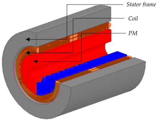
Figure 1.
3D Model of the BLDC high-speed motor.

Table 1.
Parameters of Toothless BLDC Motor.
3. Improvement Design Study
A toothless motor is based on a permanent magnet brushless DC motor with an air-gap magnetic field interacting with a permanent magnet. If there is a serious high harmonic magnetic field in the working air gap, it produces adverse additional torque, loss, vibration, and noise. The structure of the stator is no teeth and no slots, no core, and the winding form is similar to a hollow cup, in which the static friction force torque [12,13] and the mass and moment of inertia are reduced. The eddy current effect of the stator winding is fundamentally eliminated; thus, the energy loss and the high harmonic magnetic field in the air gap are reduced. However, because of the special winding of the toothless motor, the winding ends are interlinked with the permanent magnet, so there is still a large eddy current loss inside the wire.
3.1. Eddy Current Loss of a Single Wire
Eddy currents are produced by an alternating magnetic field in nature. The size and frequency of the magnetic field affect the eddy current loss of the conductor. In the superimposed winding in a sinusoidal alternating magnetic field, the mathematical model of the conductor eddy current loss is as follows [14]:
where is the eddy current loss value of a single conductor, is the axial component of the flux linkage, is the resistivity of the copper wire, Bpk is the peak flux density of the sinusoidal magnetic field, is the angular frequency of the magnetic field, and d is the diameter of the conductor.
In the original design, the direction of the magnetic field at the winding location is constantly changing, and the magnetic field is not the standard sinusoidal alternating field. To calculate the loss, the magnetic flux density is divided into radial and tangential components, and each component is converted into multi-order odd harmonics by Fourier decomposition. The magnetic field of the winding is approximately to a multi-order sinusoidal alternating magnetic field for the calculation Finally, the analytical calculation model of the eddy current loss of a single conductor is as follows [15,16,17]:
where N represents n harmonics, is the angular frequency of n harmonics, BrN is the amplitude of the radial flux density of n harmonics, and Loss Calculation BtN is the amplitude of the tangential flux density of n harmonic waves.
In this study, it is important to obtain the relationship between the eddy current loss and the parameters L and d of the winding structure. Thus, the improved parameters are related to L and d based on the analytical calculation model of the eddy current loss.
When the axial component of the flux linkage L is shorter, the eddy current loss will be lower. This is equivalent to decreasing the axial component by increasing the effective conductor length of the part perpendicular to the magnetic field, thus reducing the eddy current generated at the overhangs of the winding. Therefore, the ratio of effective length to overhang length of lap winding is proposed as an improved parameter under the condition that the overall length of the winding remains unchanged.
3.2. Polar Arc Coefficient and Permanent Magnet Loss
Because the rotor structure of the original model is polar-mounted PM structure, the polar-arc coefficient is 1.0. Referring to the analysis of Equations (3)–(5), it can be observed that the polar arc coefficient has a great influence on the fundamental air gap flux density, which affects the eddy current loss value of PM, especially at high frequency. Therefore, the original design will produce a large loss at the PM [18,19,20,21].
The stator core and winding of the original model are improved, and a new rotor structure is proposed by combining theoretical analysis with FE analysis. It is of great significance to the research of toothless BLDC motor.
3.3. Improvement Methodology
In the paper, a multiparameter improvement methodology is presented for the BLDC high-speed motor. This method is to investigate the performance influence of the BLDC motor through the analysis of the given design parameters in the limited range. In the winding improvement design, the effective length of winding is a very important parameter, and its influence on eddy current loss is explored. According to theoretical analysis, another parameter is the number of parallel wires, which is also the influencing factor of eddy current loss of Brushless DC motor winding. For the rotor, two variable parameters of pole arc and permanent magnet thickness are analyzed to improve the rotor structure.
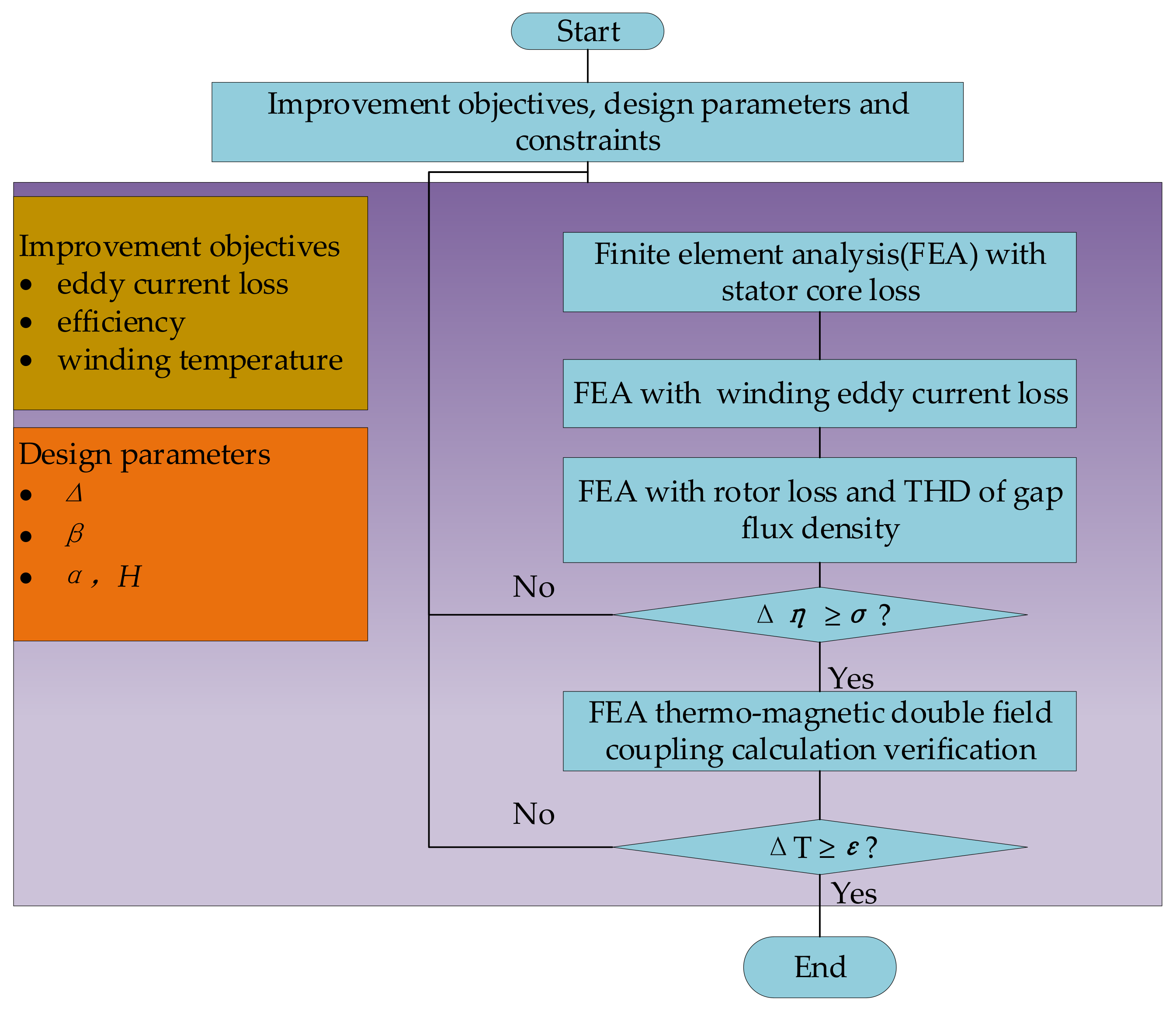
In this study, the multiparameter improvement methodology is shown in Figure 2. The improvement objectives are the loss reduction, an efficiency improvement of minimum 3% and the winding temperature reduction of minimum 10 °C. The design parameters are ratio of effective length to overhang length () and the number of parallel wires (), rotor pole arc () and PM thickness (H). FEM was used to calculate the eddy current loss and temperature distribution by the magnetic–thermal coupling simulation.
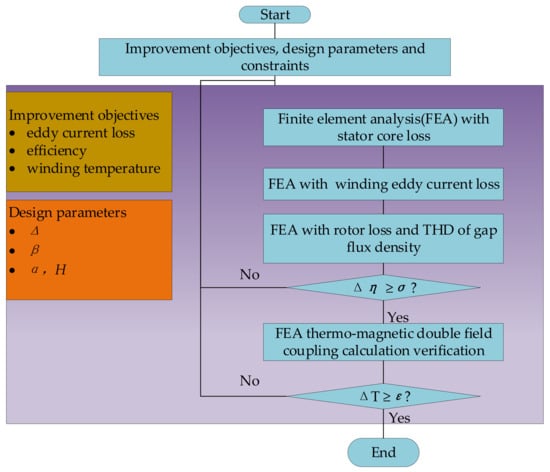
Figure 2.
Multiparameter improvement methodology flow chart.
Under the condition that the out power P0 remains unchanged, the parameters of each part of the windings are selected to meet the requirements of the improvement objectives. The parameter of ratio is give in the limited range, considering the limitation of lap winding manufacturing technology. To ensure its accuracy, the value range of the parameter is set from 0.0 to 2.0 with an interval of 0.5. Further, for the numbers of the parallel wires , considering the standard wire gauge size and the winding technology, it is set to the range of 1 to 30.
In addition to improving the winding of the motor, the method was used to improve the rotor structure through the analysis of the two design parameters. Polar arc coefficient is in the range of 0.7, 0.75, 0.8, 0.85, 0.9, 0.95, 1.0, and PM thickness is in the range of 2.0 mm, 2.5 m, 3.0 mm, 3.5 mm. Finite element simulation analysis was carried out to compare the rotor loss and the harmonic content of air gap flux density before and after improved to verify the rationality of improvement method. Under the condition that the no-load back EMF waveform and output power waveform are not distorted, the improvement objectives and constraints can be expressed as
where Pn is the rated power, and Un is the rated voltage. is the difference between the original design and improved design, and is the efficiency improvement objective, valued at minimum 3%. Then, by magnetic-thermal fields coupling simulation, is the difference in temperature between the original design and the improved design, and is the temperature improvement objective, valued at minimum 10 °C. The design parameters of the structure were studied to reduce the eddy current loss and achieve the improvement objectives.
4. Stator Loss Calculation and Improvement Study
4.1. Stator Iron Loss Calculation
References [22,23] proposes a new method to calculate the stator iron loss, which considers the interaction of two magnetization modes and harmonic magnetic field. In this method, the radial and tangential magnetic density amplitudes are decomposed and calculated, and the calculation equation is shown.
where Brm and Btm are the maximum values of the radial and tangential magnetic densities of the harmonics. Kh and Ke are the hysteresis loss coefficient and the eddy current loss coefficient, respectively. f is the frequency, and k is the order of the harmonics.
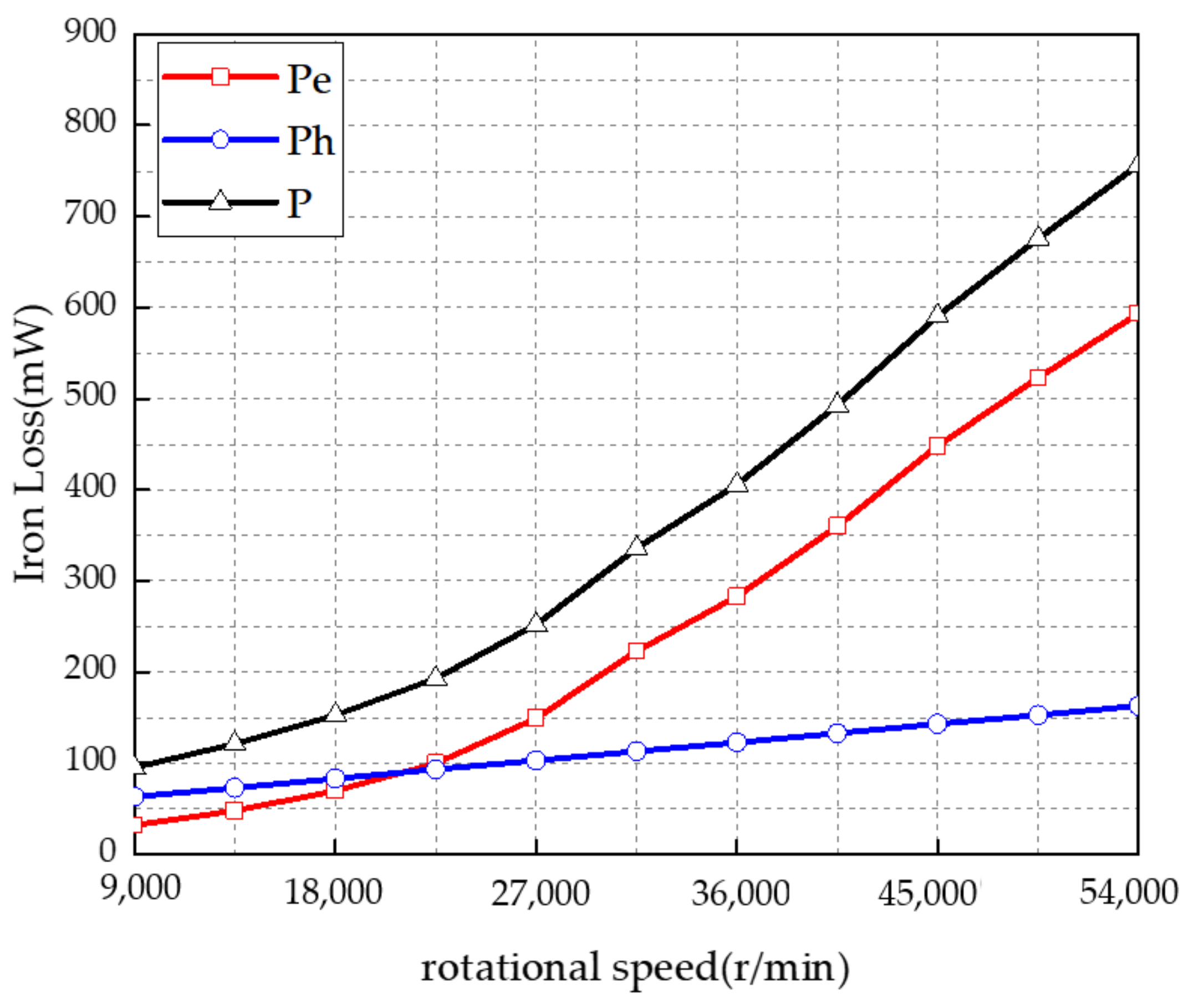
It can be observed from Equation (7) that the loss of stator iron core mainly depends on the loss coefficient of iron core material and changes with the change of magnetic field frequency. In the paper, the stator core material is silicon steel sheet, and the thickness is 0.2 mm with low loss. The above average magnetic density method of Equation (7) is used to calculate the stator iron loss at different frequencies, as shown in Figure 3. Hysteresis loss is the main component at the low frequency, but at the high speed, when the speed exceeds 18 k r/min, the eddy current loss will increase sharply. From the Figure 3, the stator iron loss of the BLDC motor is 524 mW at the speed of 47,000 r/min with 783 Hz, in the paper.
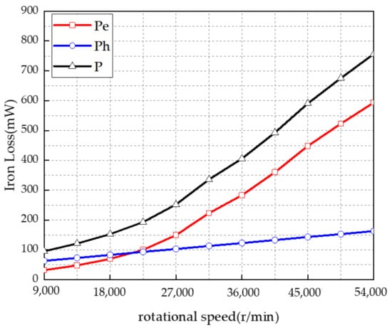
Figure 3.
Stator iron loss curves with different rotational speed.
4.2. Determing Improvements of Parameter
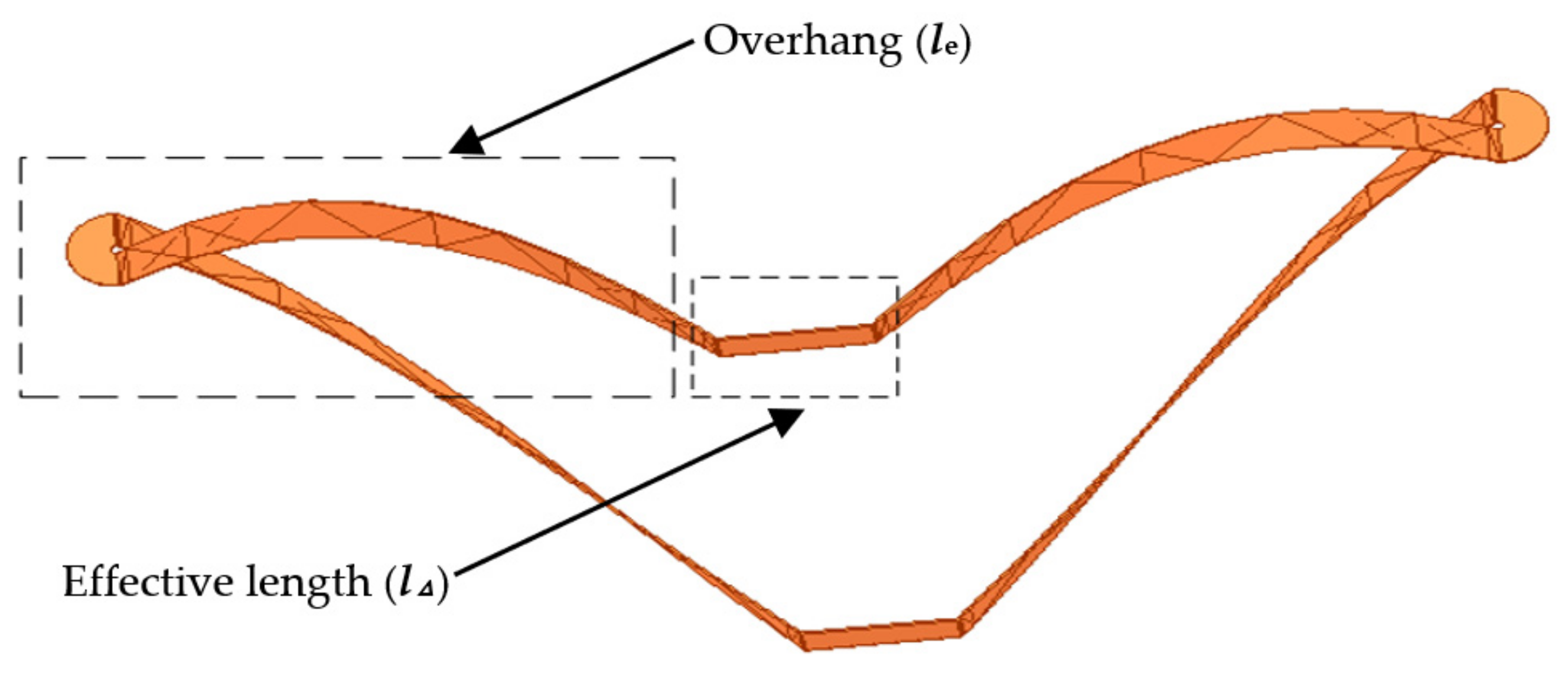
Defining l as the total length of a single winding, is the effective length, and is the overhang section, is the ratio of and , referring to Equation (8). A three-dimensional FEA model of the winding is shown in Figure 4.

Figure 4.
FE model of single winding.
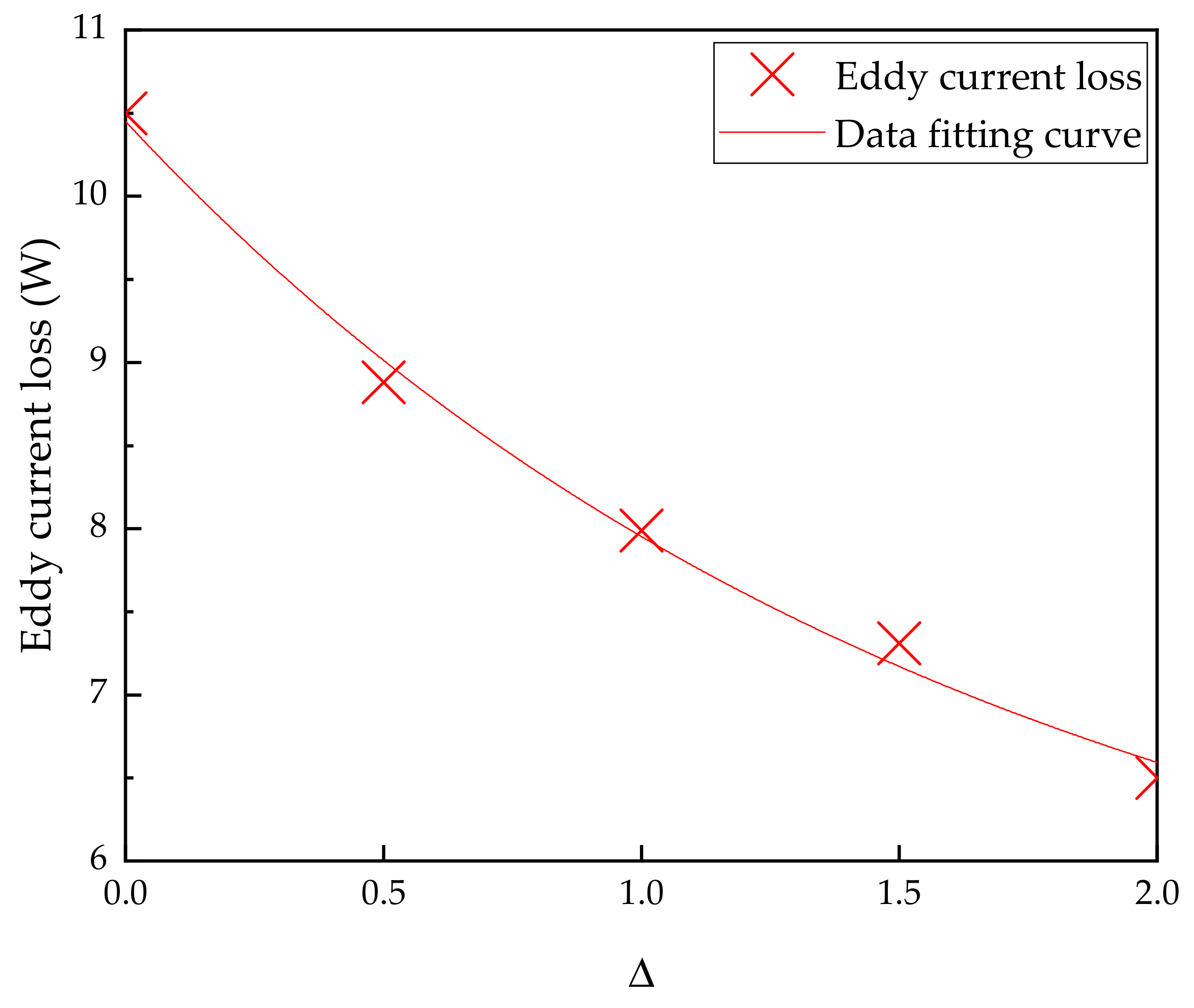
The winding parameters improvement is used to investigate the relationship between the effective length of the winding, eddy current loss, copper loss, and efficiency performance, such as the impact of this section. First, at the rated speed of 47,000 r/min, FEA was used to determine the relationship between the and eddy current loss Pe, which validates the above theoretical analysis. Figure 5 shows the peak value of the motor eddy current loss corresponding to different .
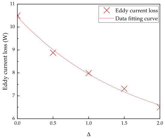
Figure 5.
Maximum eddy current loss curve at different .
It can be observed from the figure that is inversely proportional to the eddy current loss generated in the lap winding. When is 0, the eddy current loss generated by the motor is 10.5 W, which is the original design. It is known that the eddy current loss is too large, approximately 12% of the rated power. Then, a large heating is produced as the thermal field. When is 2, the eddy current loss is only 6.5 W, sharply decreased to only 7% of the rated power. It can also be observed that the improved parameters are of great significance to reduce the eddy current loss of the motor. This is because the essence of increasing is to increase the flux length between the lap winding and the magnetic field in the vertical direction.
According to the simulation results, the mathematical expression is obtained between the eddy current loss and the lap winding parameters of the BLDC motor, referring to Equation (9). The accurate quadratic function expression of and eddy current loss is summarized, which provides a reference for the structural design of permanent magnet BLDC motors.
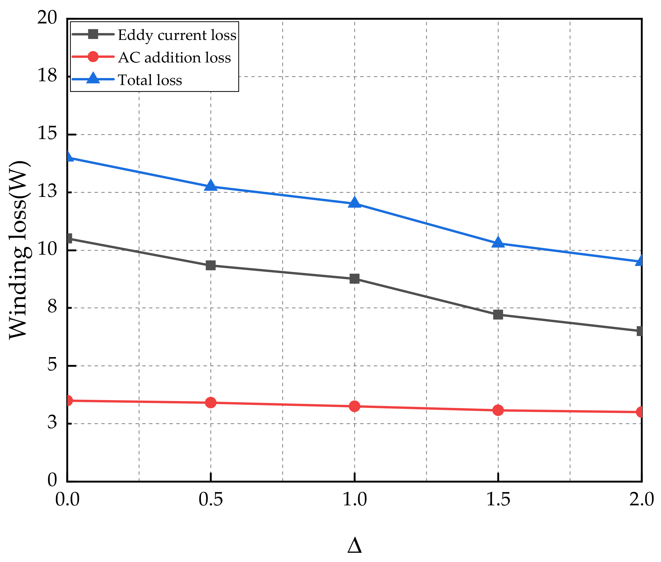
Based on the eddy current loss and addition loss of lap windings, the total loss of both is simulated; observed in Figure 6, the total stator loss of the BLDC motor decreases with the increase in the effective length ratio of lap winding.
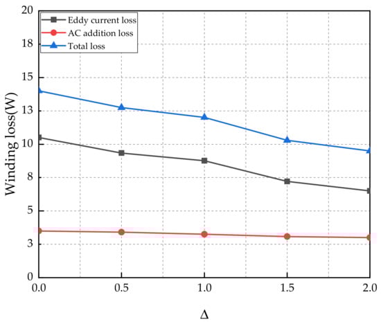
Figure 6.
Curves of winding loss of toothless BLDC motor with different .
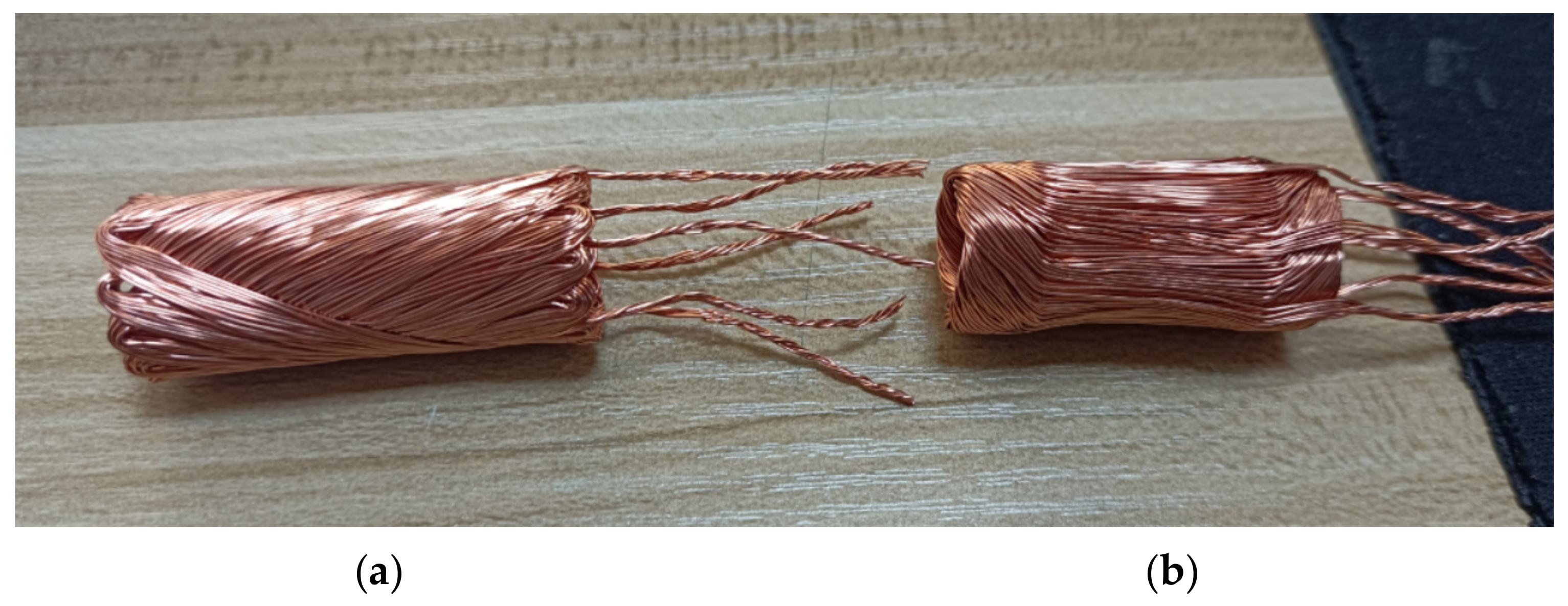
The original model of the winding is with of 0, which means no effective length of the winding. The total loss of the motor in the rated state is 14 W. When is 2, the effective length is 2 times that of the overhang. The total loss generated by the motor is the lowest, which is 9.5 W. In motor design, the effective length of winding is very important. Based on the above simulation results and the improvement of winding process, the effective length of the improved design model is very ideal, accounting for twice the overhang. Not only the eddy current loss is greatly reduced, but also the winding is smaller. Photo of Interior of stator winding—for both the original and improved motors—is as shown in Figure 7. Therefore, 2 is selected as the ratio of lap winding parameter for the improved result.
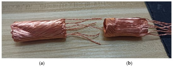
Figure 7.
Photo of interior winding for both the original and improved one: (a) Original ( = 0); (b) Improved ( = 2).
4.3. Determining Improvements of Parameter
Combined with the theoretical analysis, the FEA model was used to analyze the eddy current loss. After the parameter () of the windings are determined, the number of parallel wires () is also researched. The mathematical model of the number of parallel wires and the diameter of the single wire is as follows:
Referring to (10) and (11), represents the number of parallel wires, Ac represents the cross-sectional area of a single wire, I1 represents the rated current of the motor, a1 represents the parallel branch number, J represents the current density of the motor, and d represents the diameter of a single wire.
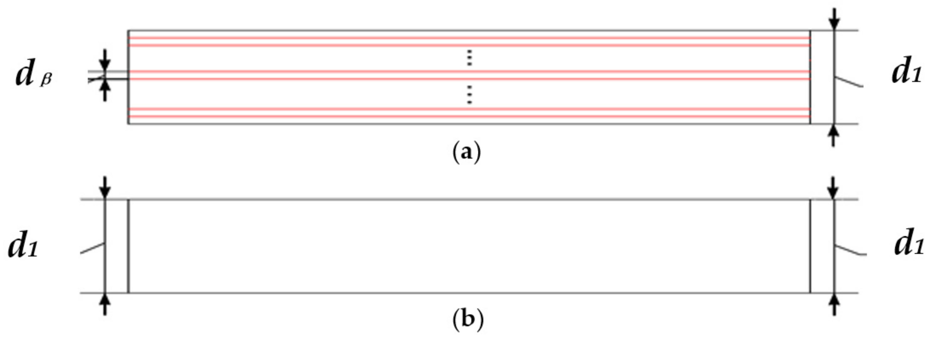
It is known that the thicker the conductor, the greater the eddy current loss. In this study, the winding overhangs are superimposed and embedded into the frame, which leads to a large eddy current throughout the circuit of the conductor. In particular, at the rated speed of 47,000 r/min, it is important to reduce the eddy current. The improved method is to reduce the path in which the eddy current goes through the circuit of the conductor; that is, the diameter of a single wire can be reduced by increasing the number in parallel wires. Figure 8 shows the diagrams, Figure 8a represents multi-wire in parallel, and Figure 8b represents one wire. By analogy, the case of multiple wires in parallel is similar to that of multiple silicon steel laminated sheets by using thinner silicon steel sheets to reduce the eddy current loss.
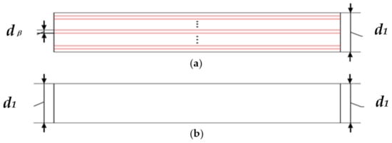
Figure 8.
Models of one conductor. (a) wires in parallel; (b) 1 wire.
Therefore, the improved method is to analyze the eddy current loss of the stator impact assessment by giving the parameter in a limited range of values.
Considering the standard wire gauge size and the winding technology, the selection of the numbers of the parallel wire limits specified is from 1 to 30, and the diameter of wire is from 0.5 mm to 0.09 mm. The Table 2 lists the numbers, setting 1, 5, 10, 15, 20, 25, and 30. The original model is 5 wires in parallel, and 22 turns are connected in a series of BLDC motors.
Table 2.
Parameter of the winding.
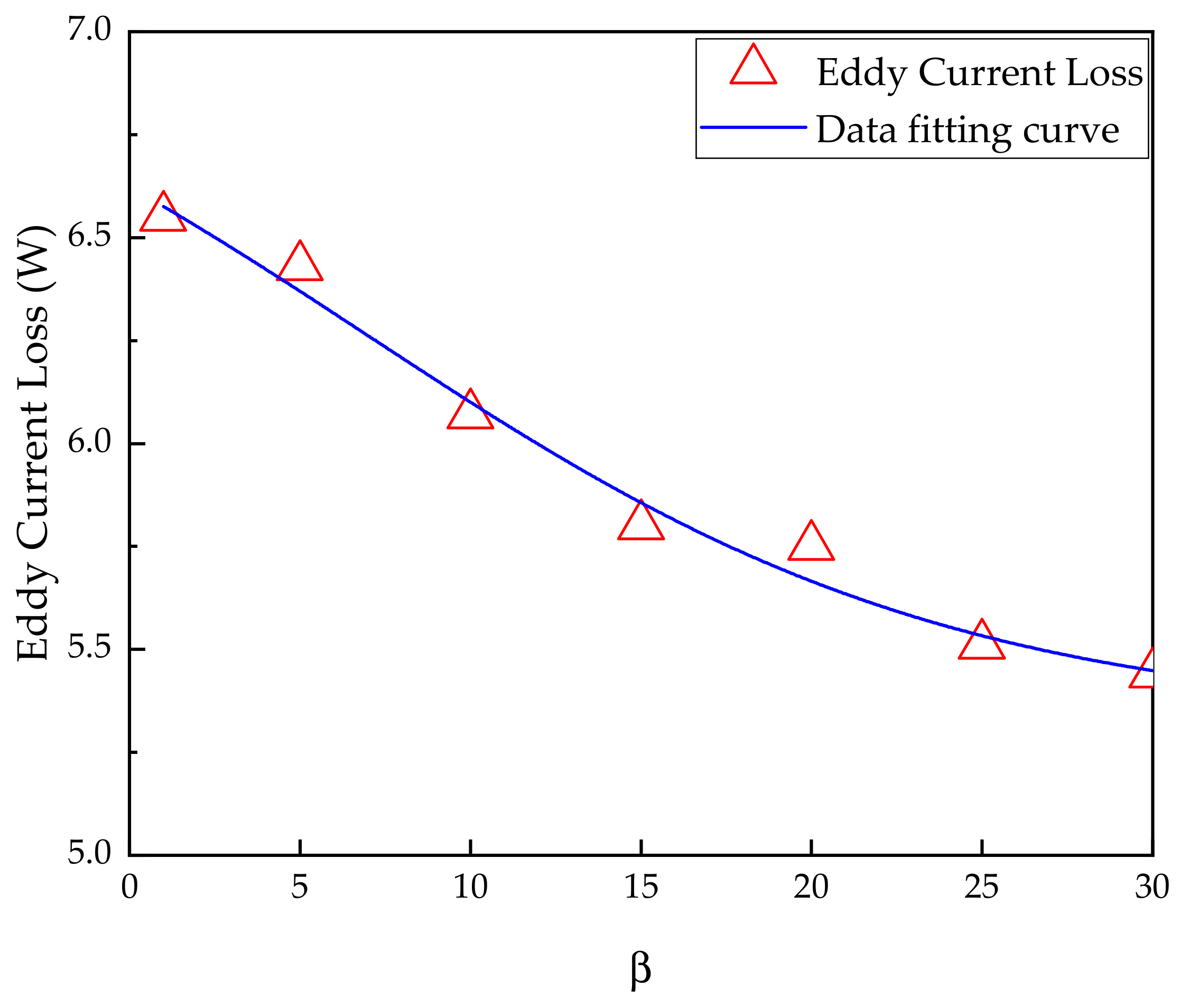
The premise of the improved method is that the current density of the conductor remains unchanged. From Table 2, it can be observed that as the value increases, the diameter of the wire decreases, and the eddy current loss also decreases accordingly. The original model is 5 wires in parallel, and the current density is 5.0 A/mm2. To reduce the eddy current loss at the overhangs of the lap winding, it is established in the finite element model of the motor to calculate it with different values of . Figure 9 shows the eddy current losses corresponding to different numbers of parallel wires.
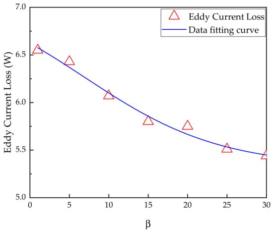
Figure 9.
Maximum eddy current loss curve at different wires in parallel.
According to the simulation results, the mathematical expression is summarized between the eddy current loss Pe and the number of parallel wires , as shown in (12). The expression can help to calculation the eddy current loss, choosing conveniently and taking into account the results at the limits specified from 1 to 30 wires. Additionally, it can provide a reference for the winding design of the BLDC motor.
From Figure 9, it can be drawn that the stator eddy current loss of the motor decreases exponentially with the increase of the number of parallel wires. When is 1, the maximum value of the eddy current loss is 6.55 W. When is 5 (that is, the original design), the eddy current is 6.43 W. When is 25 or 30, the value is almost the same; the eddy current loss generated by the motor is the lowest, which is 5.51 W. For the special application scope of the motor discussed in this paper, the principle of the improvement method needs to meet the requirements of wire gauge size, winding structure and technology. The diameter of 0.1 mm is the best choice for improvement, which equals to 25. Therefore, 25 was selected as the number of parallel wires of the winding for the improved result in this study.
4.4. Characteristics of Improved Model
FEA models were performed in 3D with a coil in one phase. They are based on the original model with five wires in parallel, and the improved model with 25 wires in parallel. The result of the improved coil is compared with that of the coil at the same position as the original one. The eddy current density cloud images of the original and improved models are shown in Figure 10.
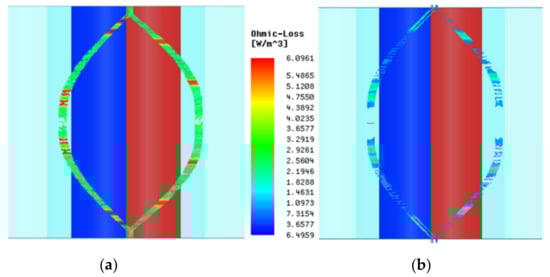
Figure 10.
Cloud images of eddy current loss density of front and rear windings: (a) Original; (b) Improved.
In this study, the improvement methods are used to increase the effective length of the winding and wire number in parallel. Based on the theoretical calculation, the winding coefficients do not change. A no-load analysis was carried out on the improved model. Compared with the original design, no distortion occurred in the improved no-load back potential. As shown in Figure 10, the eddy current loss density of the improved winding is significantly reduced. This change trend can be observed from the cloud images in that the eddy current is obvious occurring at the overhang of the winding. Therefore, from the cloud images, the result of the eddy current loss density with improved design is approximately 40% lower than the original one. Figure 11a shows the improved no-load EMF waveforms with one turn. Figure 11b shows the air-gap flux density of the improved model.
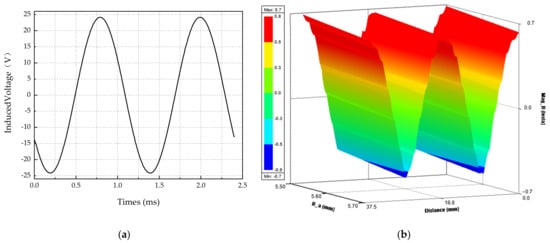
Figure 11.
Performance curves of improved motor: (a) No-load EMF waveforms; (b) Air gap flux density.
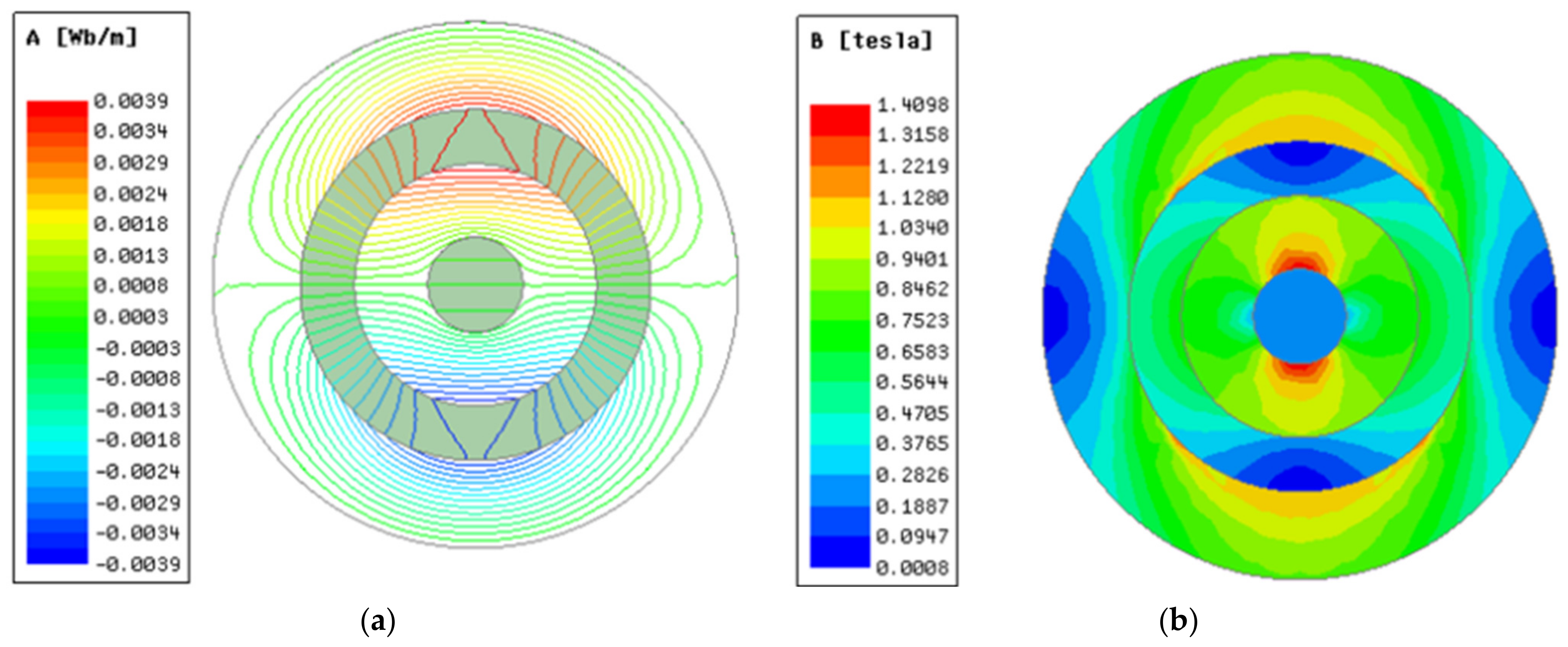
The improved method needs to ensure that the no-load back EMF remains unchanged and the magnetic flux distribution is not affected. In order to verify the rationality of the parameters of the lap winding of the toothless BLDC motor, the FE calculation was carried out on the improved model. The magnetic flux distribution, magnetic density, and gap flux density of the motor poles under no-load conditions are shown in Figure 12a,b.

Figure 12.
Magnetic field distribution images of the improved BLDC motor: (a) Magnetic intensity flux; (b) Magnetic flux density.
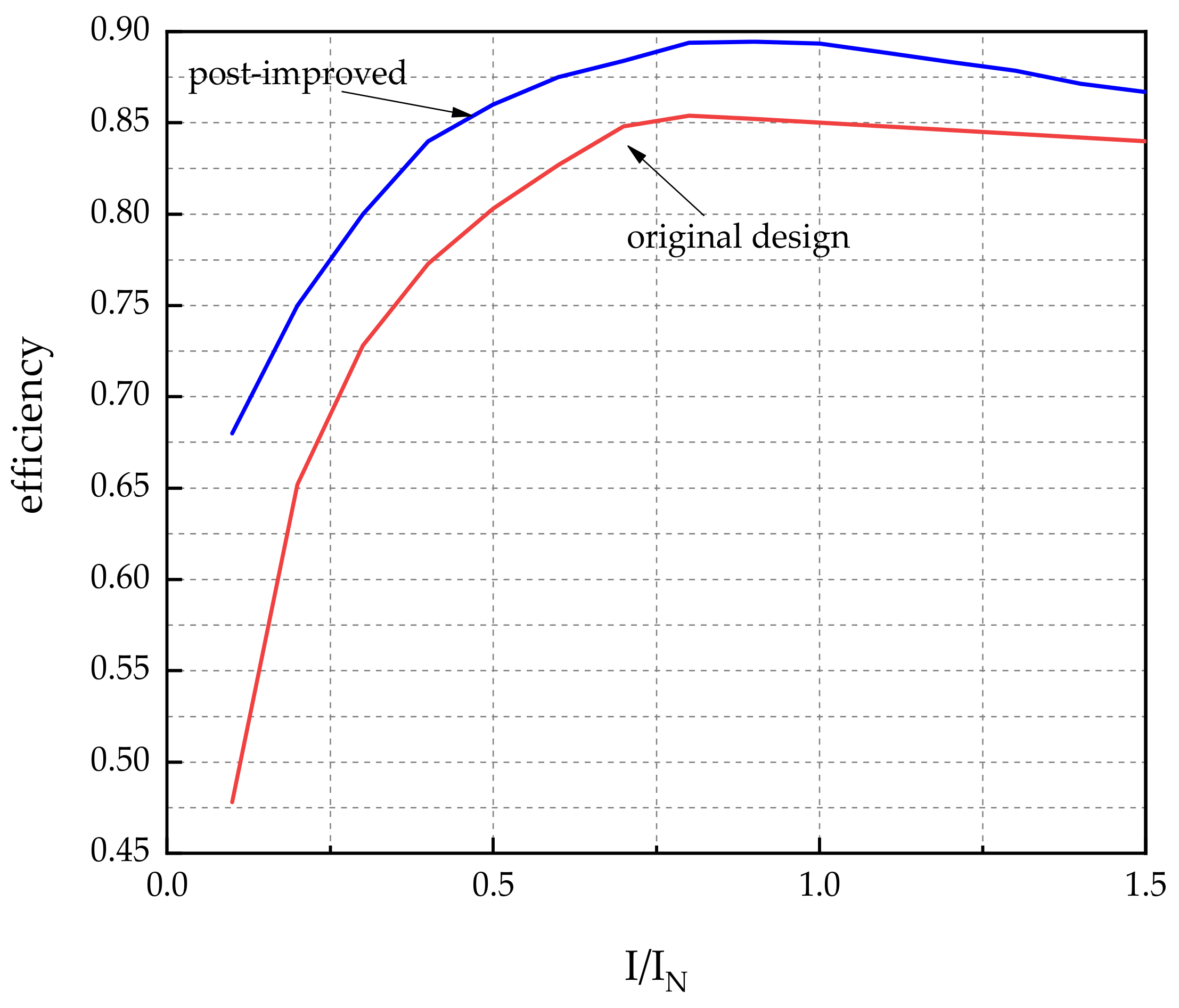
Furthermore, the output characteristics are compared with the original design, and the performance advantages of the improved toothless BLDC motor are explored. As shown in the figure below, the efficiency of the improved design is compared with that of the original design by applying different load currents at a rated speed of 47,000 r/min. To compare the accuracy of the results, the FE calculation results of efficiency under 16 conditions ranging from 0 to 1.5 times of the rated current of the given motor excitation are selected for comparison. The curves are shown in Figure 13.
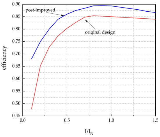
Figure 13.
Curves of efficiency with current for the original and improved design.
As can be observed from Figure 13, the efficiency of the improved motor is 89.6%, which is 4.6% higher than the original design at the rated current, which achieves the improvement object of 3%. However, when the current is higher than the rated current, the copper loss is proportional to the square of the applied current, and the proportion of DC copper loss in the total loss will increase. In this study, the eddy current loss was researched and calculated in detail. In the improvement study, two parameters are determined, the ratio as 2 and as 25. This study resulted in a 34.75% reduction in the losses and a 4.6% increase in the efficiency of the improved model compared with the original design.
5. Proposal of New Rotor Structure
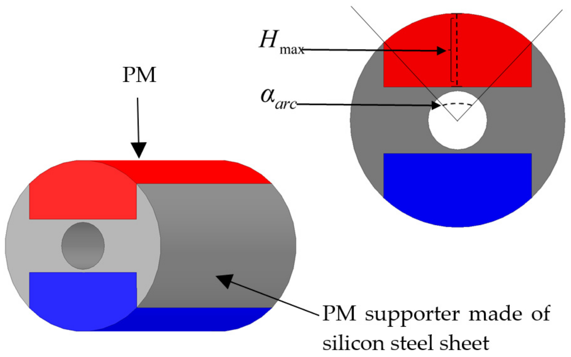
Due to the original design using permanent magnets of the same length as the housing, massive harmonics are generated in the air-gap magnetic field, resulting in more rotor losses. Therefore, in this section, a new rotor structure is proposed. The structure is composed of PM and PM supporter. Its structure diagram is shown in Figure 14.

Figure 14.
Internal structure diagram of new rotor.
The new rotor structure is derived from the improvement of the original rotor model by cutting the poles of a two-pole surface mount PM. The two most important parameters for PM are polar arc coefficient and PM thickness . The expressions of two parameters are illustrated in Equations (3)–(5). In order to find the improved rotor geometric parameters, the variable parameter is presented to analyze the influence on the fundamental wave value and harmonic content of the air-gap flux density. The relation of PM rotor loss and , is referring to the analysis of the Equations (13)–(15).
where is the saturation coefficient of the main magnetic circuit; is the air gap coefficient; is the air-gap flux density; is the length of air gap; is the vacuum permeability; is the magnetic field intensity of PM; is the arc length occupied by the Angle between the PM and steel; is pole pitch; is the inner diameter of rotor; is the pair of poles.
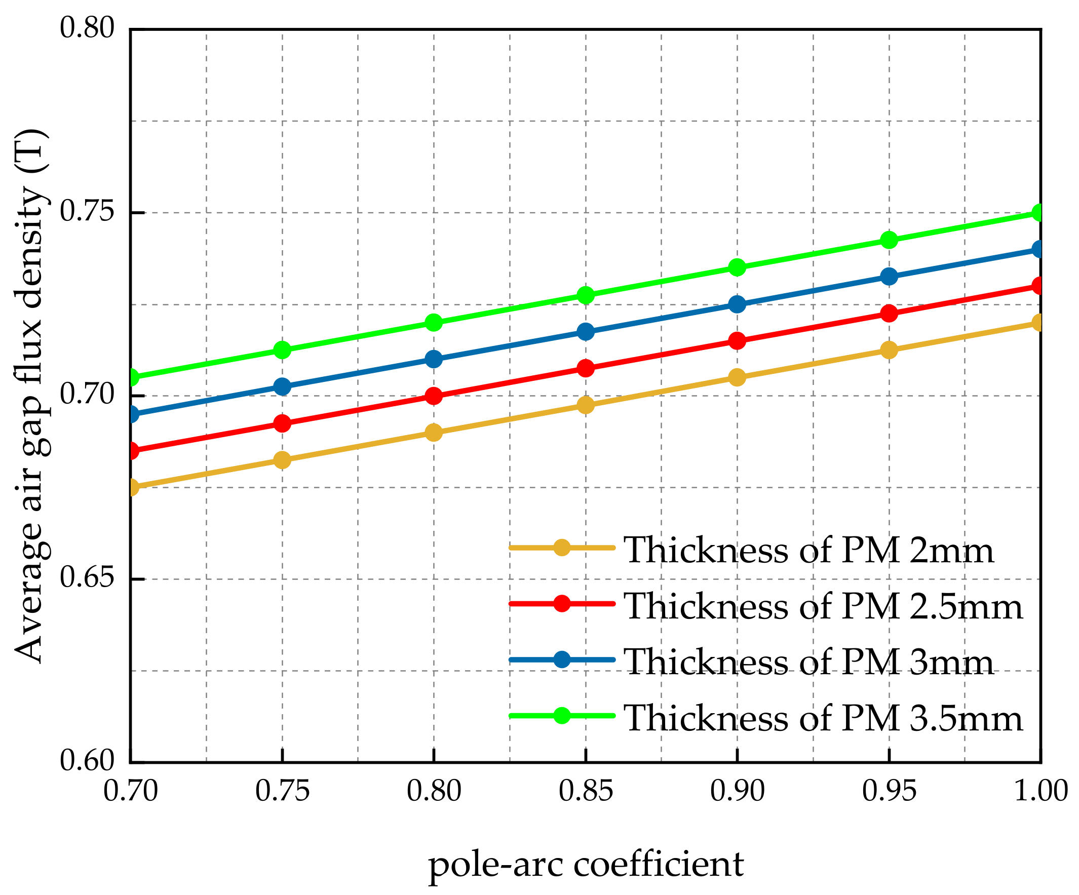
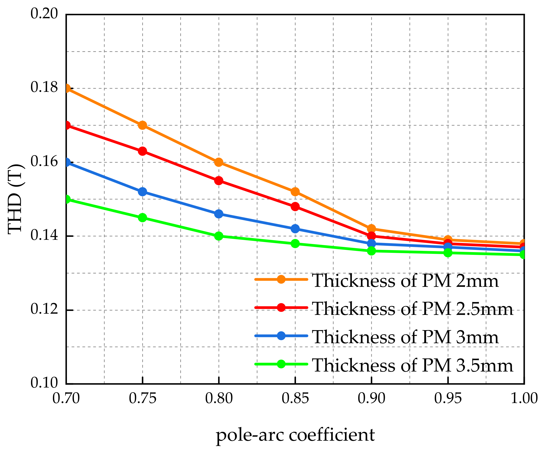
Through calculation and measurement, is 1.0 in the original model, and is 3 mm. Referring to the above equation, due to the limitation of the application scope of the original model, the range of the thickness of the surface mount PM is from 2 mm to 3.5 mm with an interval of 0.5 mm. To analyze the air-gap flux density, the value range of is given from 0.7 to 1.0 with an interval of 0.05. The coupling analysis of and is carried out, and the comparison results are shown in the Figure 15 and Figure 16. From Figure 15 and Figure 16, with different PM thickness, when the pole-arc coefficient is increasing, the air-gap magnetic flux density is increasing linearly, but THD is decreasing accordingly. In the range of from 0.9 to 1.0, THD did not change significantly.
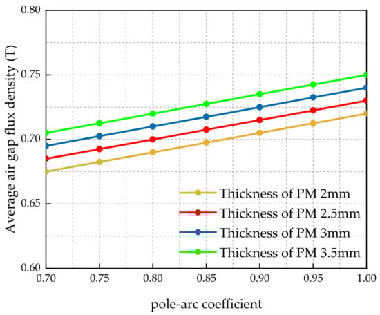
Figure 15.
Variation of air gap magnetic density fundamental wave with and .
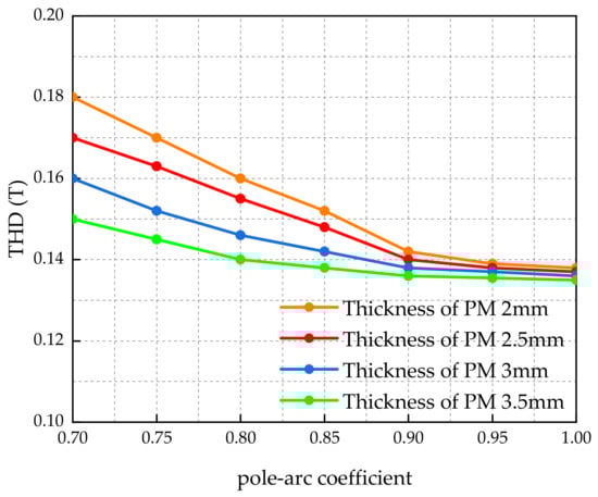
Figure 16.
Variation of THD with and .
To maintain the air-gap magnetic flux density of 0.7 T as the original design, it is analyzed that improved result is value as 0.8 and as 2.5 mm, considering fabrication allowance. The rotor parameter original and improved model is as Table 3, PM volume of improved model is saved 15% than the original one.
Table 3.
Rotor structure comparison.
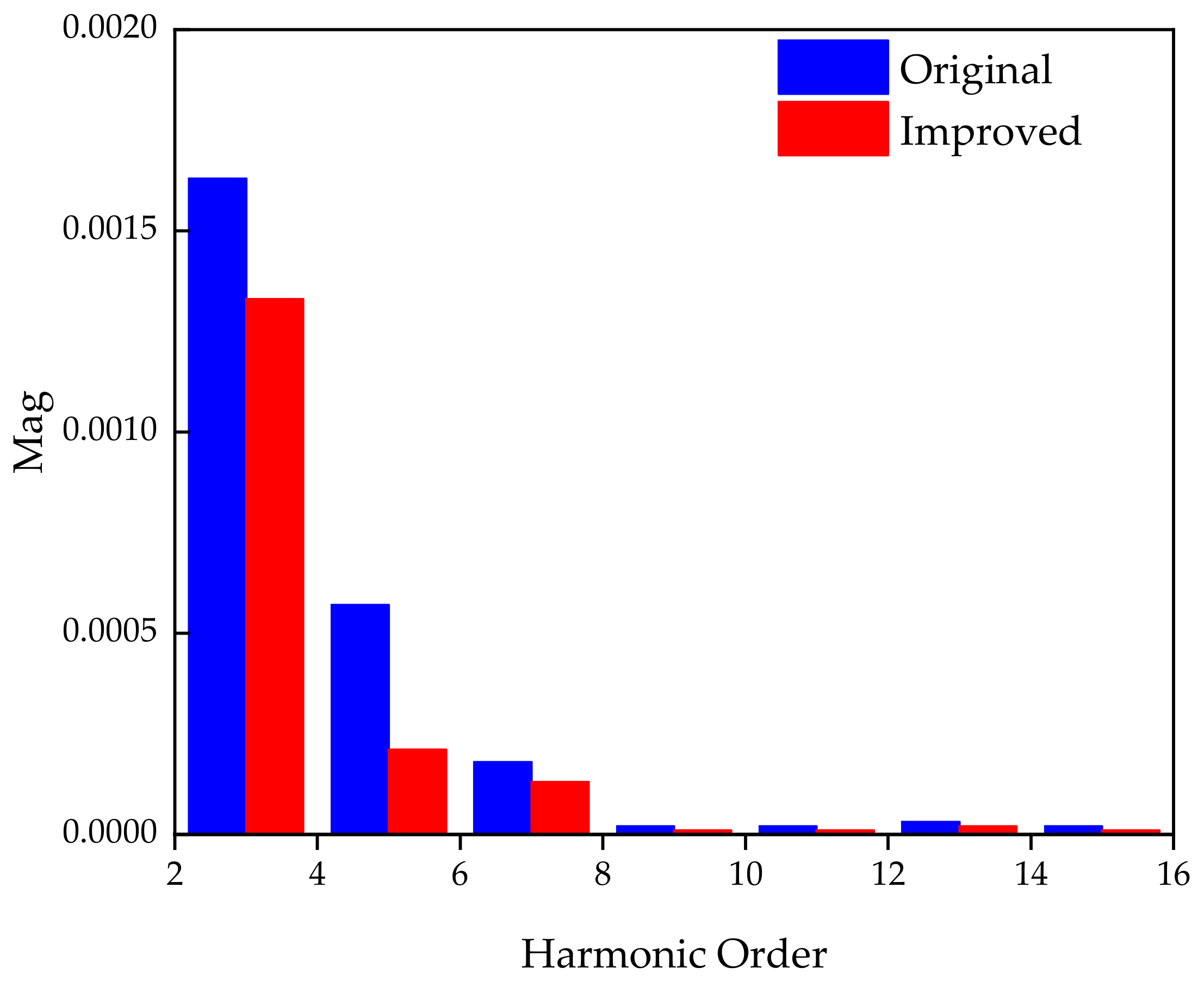
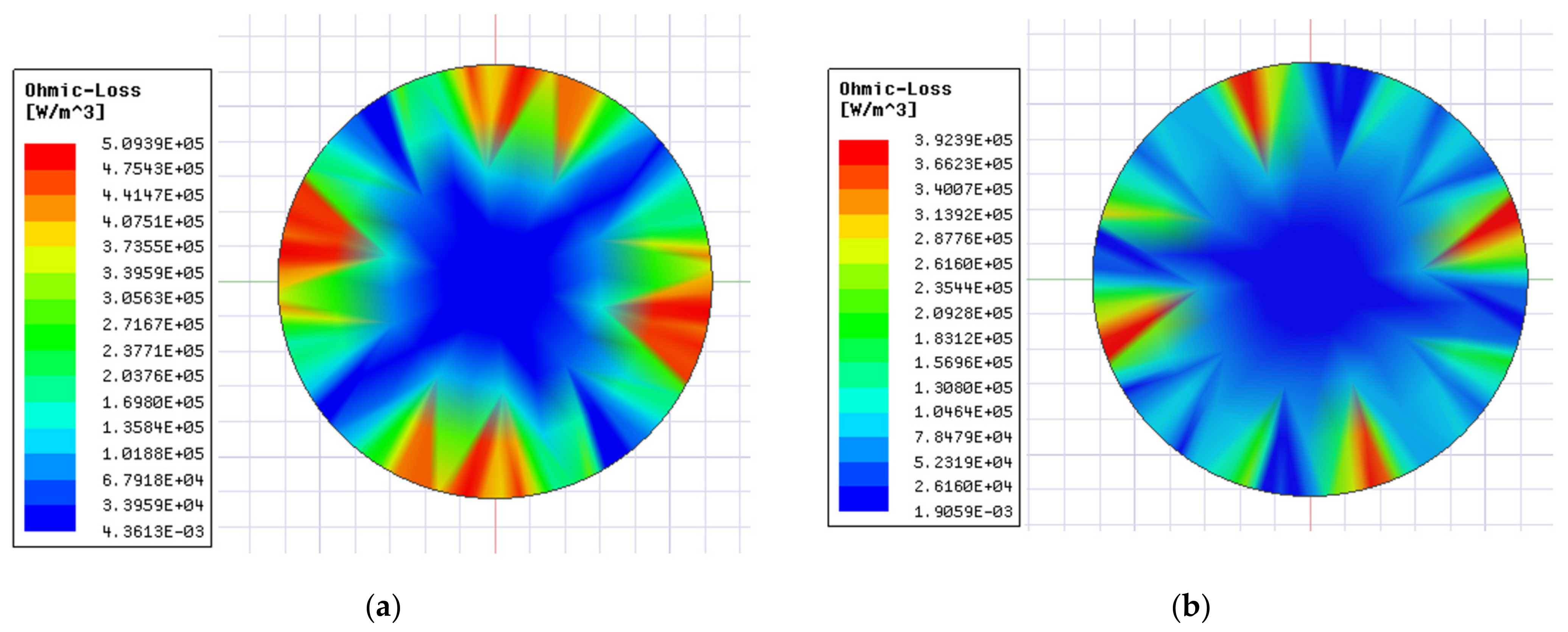
According to the theoretical derivation, and maintaining the air-gap magnetic flux density, it is analyzed with THD and eddy current loss between original and improved one. Firstly, the air gap flux density of the motor was decomposed by FT to observe the THD change as Figure 17. Then the eddy current loss of the rotor was calculated as Figure 18 with running at rated operating conditions. The improved results from Figure 17 and Figure 18 concluded that THD is decreased by 20.97%, the rotor eddy current loss is lower by 22%, compared to the original one.

Figure 17.
Harmonic distribution by Fourier decomposition.
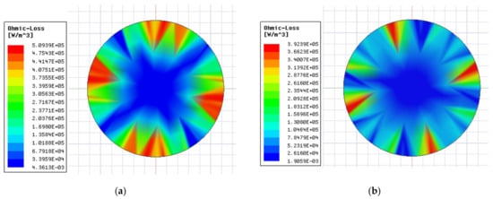
Figure 18.
Cloud images of the rotor loss (a)Original; (b) Improved.
6. Magnetic–Thermal Coupling Simulation
In this study, the research object is a BLDC motor. Because it is mainly used in ventilators, the working hours of the ventilator are 7500 h as minimum during continuous operation. Thus, temperature is a key factor, which is the foremost improvement objective. Through the improvement process and the above simulation, the improved design was superior to the original design in terms of the electromagnetic field. It is necessary to simulate the temperature distribution under the improved design parameters and to be verified and compared with the original design.
The calculation of the temperature rise of a motor involves electromagnetism, computational fluid mechanics, material science, heat transfer, and other aspects of knowledge, and an accurate calculation of the temperature rise of the motor needs to establish a complete mathematical physical model. The heat transfer phenomenon usually includes three basic forms: heat conduction, convective heat transfer, and radiation. Because the radiation in the motor accounted for a small proportion and can be ignored, the heat transfer phenomenon in the motor mainly includes heat conduction and convection heat transfer.
The Fourier law of the heat conduction equation links the temperature field distribution with the heat flow [24,25,26], and is expressed as Equation (16):
In the equation, is somewhere on the object, is the heat flux vector, and is the thermal conductivity coefficient. The negative sign in the equation indicates that the direction of heat flow is opposite to the direction of the thermal conductivity temperature gradient. The thermal conductivity differential is expressed as Equation (17):
where is the density of the object and is the object’s constant volume heat capacity. For the steady-state thermal conductivity process, the temperature does not change with time, and the thermal conductivity differential equation is Poisson’s equation, which is expressed as Equation (18):
If there is no heat source in the body, the differential equation of thermal conductivity is the Laplace equation, which can be expressed as Equation (19):
In addition to heat conduction, convective heat transfer is another important heat transfer phenomenon in motors. Based on fluid flow, convection heat transfer can be divided into natural convection heat transfer and forced convection heat transfer: Equation (20).
In the convection heat transfer process, there is both the heat conduction process inside the fluid and the heat transfer process between the fluid and solid surface. Therefore, the continuity differential equation and motion differential equation are involved when describing convective heat transfer using mathematical physical equations. The differential equation of the fluid motion is expressed as
For natural convective heat transfer, it is assumed that the buoyancy direction is the same as the X-axis direction in the Cartesian coordinate system, and the above equation is expanded as follows Equations (21) and (22):
The main heat source of the BLDC motor is the copper loss and eddy current loss of the winding. Although the relative length of the motor increases after improvement, the influence of the increase in the winding on the temperature field of the motor during normal operation is minimized owing to the increase in the convection heat transfer part between the end of the winding and the air after improvement and the decrease in the eddy current.
The advantages of the improved motor in the winding temperature under the influence of eddy currents were also investigated. The 2D FEA calculation model of the motor is established to study the electromagnetic thermal two-field coupling simulation in a natural cooling environment, and the improvement process is shown in Figure 19.
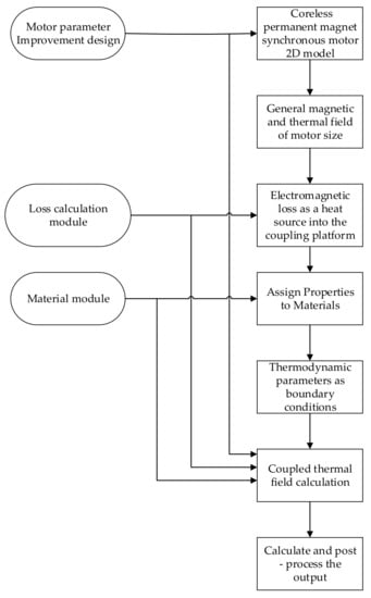
Figure 19.
Two-field coupling calculation process.
The transient distribution of the motor temperature field changes with the running time, from the initial state to the stable state. The temperature distribution of the motor before and after improvement at the initial temperature changes very little. Therefore, in the paper, the temperature distribution of the motor after reaching the steady state is simulated in Figure 20 for the original and improved motor.
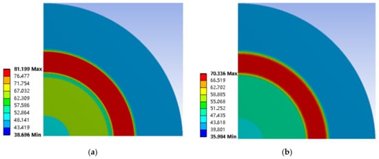
Figure 20.
Distribution diagram of winding thermal field of the BLDC motor: (a) Original; (b) Improved.
As shown in Figure 20, when the motor reached the steady state, maximum winding temperature in original design was 81.199 °C, and that of the improved winding was 70.336 °C, which decreased by 13.4%. After the improvement design, the winding temperature was significantly reduced. Therefore, it can be shown that the improved BLDC motor has obvious advantages in reducing the winding temperature rise.
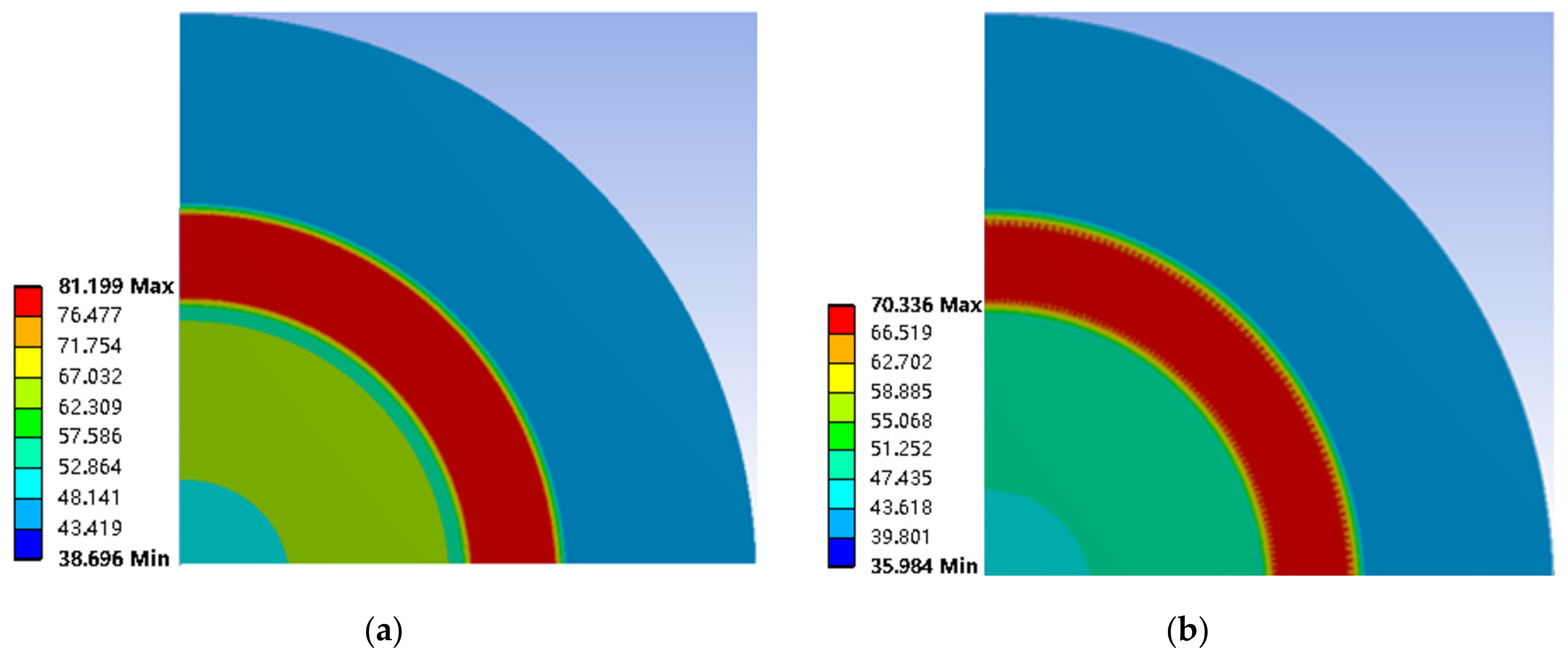
By setting the losses generated on the rotor as the boundary condition in thermal field, it can be drawn that the new rotor structure has better heat dissipation than the original one in the rated conditions, due to its PM bracket made of silicon steel sheet. The thermal distribution of the rotor finite element model at the rated operating conditions before and after improvement is shown in Figure 21. The rotor temperature of the improved model was 23.71% lower than the original value. The rotor photo of the improved motor is shown in Figure 22.
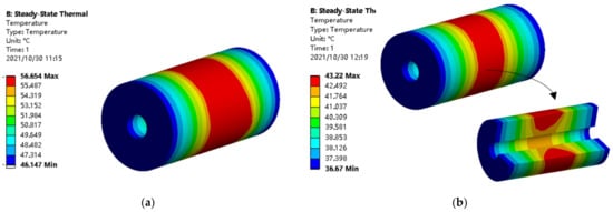
Figure 21.
Distribution diagram of rotor temperature: (a) Original; (b) Improved.
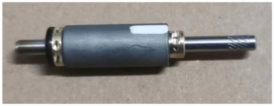
Figure 22.
Rotor photo of the improved motor.
7. Experimental Result and Comparative Analysis
In this section, the performance of the improvement content is discussed in this study and the results are verified experimentally. A BLDC motor prototype was manufactured based on the improved design. The performance test of the prototype was carried out on the experimental platform.
Firstly, the experimental motor with no-load test is powered by a turbine, as shown in Figure 23. The turbine air flow causes the motor to rotate. The probes of oscilloscope are connected to the two phases as line EMF testing. Considering the safety of the experiment and the complexity of the coupling, the speed did not reach the rated speed.
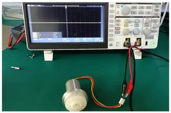
Figure 23.
Experimental test platform for motor with no-load test.
From Figure 24a, the measured frequency is 76 Hz, and the peak value of EMF is 2.48 V from the record of the EMF at this frequency through oscilloscope. Referring to Equation (23), the no-load back electromotive force (EMF) is calculated as 25.5 V at the rated frequency of 783 Hz from the record conversion.
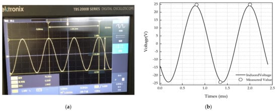
Figure 24.
Pictures of EMF calculation and experiment: (a) Measured EMF at 76 Hz; (b) EMF calculation and measured conversion at rated 783 Hz.
The motor EMF at the rated speed is verified by the no-load towing experiment, and the comparison between the test conversion results and the finite element simulation results is shown in Figure 24b. The tolerance was within 5%.
Further, the experimental platform with load test is illustrated in Figure 25. The experimental equipment consists of WT310 (Yokogawa) high-power dynamometer, GL840 multichannel temperature recorder, QG6003S power supply, motor controller and the BLDC motor, etc. The control method of the motor is maximum torque per ample (MTPA), and the efficiency test is carried out through this control mode. The motor efficiency observation experiment was carried out with load test, and the efficiency curve is shown in Figure 26.
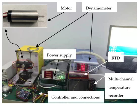
Figure 25.
Experimental test platform with load test by MTPA.
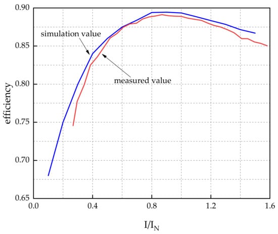
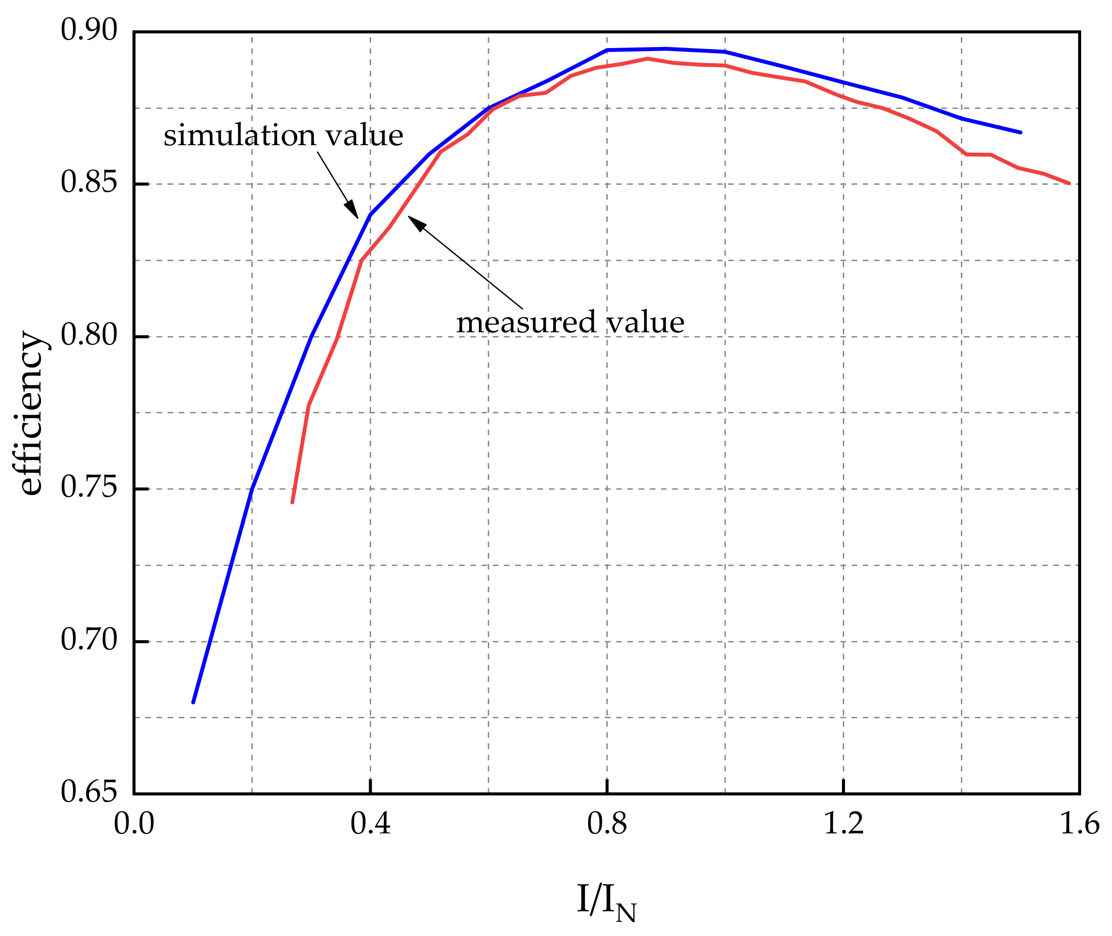
Figure 26.
Curve of prototype efficiency for the simulation result and measured result.
The efficiency is calculated from measured values. Using the following Equation (24), the torque (T), the input voltage (U) and the input current (I) are tested with different rotational speed (n) by the Dynamometer WT310. Then the output power is calculated by measuring the armature current of the dynamometer under different loads, and the efficiency curve is drawn. Measured data of the BLDC high-speed motor with load by MTPA is shown in Table 4.
Table 4.
Testing data of the BLDC high-speed motor with load by MTPA.
It can be concluded that the tolerance of efficiency between the measured and simulation results is within 3% from Figure 26, which achieves a good match.
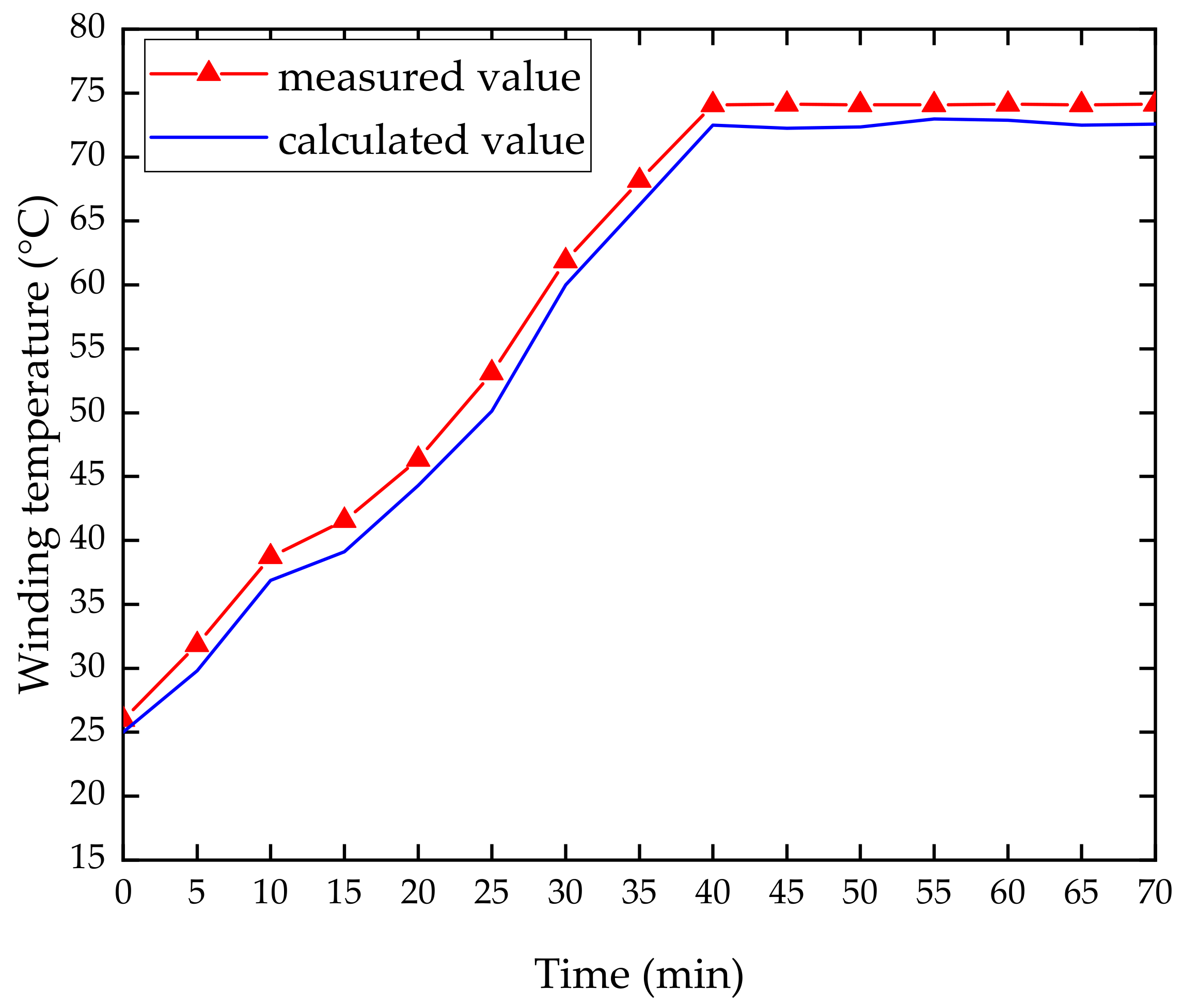
In the motor temperature rise experiment, a set of temperature rise data was recorded and analyzed using a GRAPHTEC GL840 multichannel temperature recorder every 5 min until the winding temperature reached a stable state. It was measured on the basis of the RTD (Resistance Temperature Detector), which is embedded in the winding as the thermocouple PT100. The temperature rise results of the experimental and simulation are shown in Figure 27, and the temperature rise test device is as shown in Figure 28.
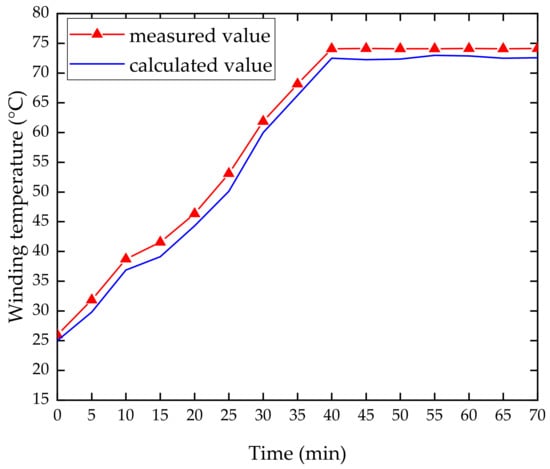
Figure 27.
Curve of temperature rise results of the measured and simulation.
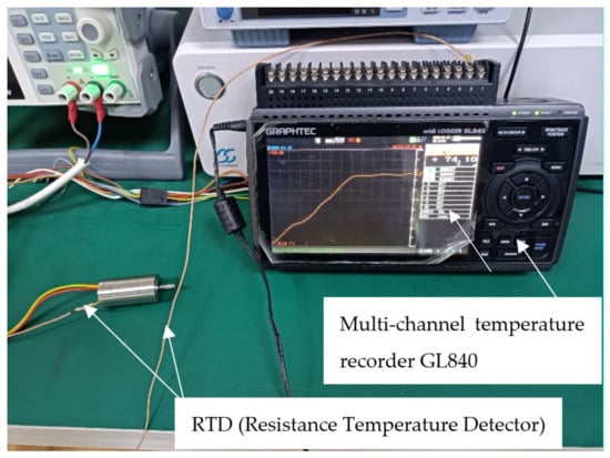
Figure 28.
Temperature rise recorder device GL840 and RTD.
It can be observed from the experimental results that the winding temperature of the motor did not change significantly after running for 40 min. The peak value of the recorded temperature is 74.1 °C, which is 5% different from the simulation result of 70.336 °C. The error between the above three experimental results and the simulation results were all within the allowable range. This proves the accuracy of electromagnetic and thermal properties simulation results, and the establishment of the three-dimensional FE model are reasonable.
8. Conclusions
In this paper, a multiparameter improvement methodology is presented to design the structure of the toothless BLDC high-speed motor. The FEM was used to analyze and calculate stator, winding and rotor loss. Furthermore, the magnetic–thermal coupling simulation is adopted to compare the performance of the improved design with the original design. Finally, the simulation results are verified by the experiments of the prototype. The following conclusions were drawn.
During the improvement process of the motor winding, the parameters are determined as of 2 and of 25. In this study, two relational expressions are summarized, which are the influence of two parameters in winding design on eddy current loss. These studies provide some reference for the winding design of high-speed BLDC motors.
In addition, a new rotor structure is proposed, including PM, a PM supporter made of silicon steel sheet and shaft. Additionally, the improved result is the polar arc coefficient of 0.8, PM thickness of 2.5 mm. This structure can reduce the eddy current loss during operation by reducing the THD in the air gap flux density of the motor, and PM volume can be also reduced without changing the performance of the motor. When the structure size of the motor is large, the volume saving of the permanent magnet is more obvious. The design method of new rotor structure provides some engineering experience for this kind of high-speed motor.
Meanwhile, compared with the original design, the total loss of the improved model was reduced by 34.75% and the efficiency was improved by 4.6%, which achieve the improvement object. The harmonic content of air gap flux density decreased by 20.97%, and PM volume decreased by 15%. To explore the influence of the improved design on the temperature rise of the motor, the temperature distribution of the motor was simulated by FE steady-state temperature field. The winding and rotor temperature of the improved model were 13.4% and 23.71% lower than the original value. The difference in temperature between the original design and the improved design is 11 °C, which achieves the improvement object.
Finally, the performance test results of the improved motor are consistent with the results calculated by the FEM, which meets the engineering requirements of the ventilator. Thus, it is indicated that the improvement methodology for the BLDC PM motor and the establishment of the FE analysis model are correct in this study.
Author Contributions
Conceptualization, J.D. and J.Z.; methodology, J.D., S.Y. and C.L.; software, S.Y. and C.L.; validation, J.D., H.R. and C.L.; formal analysis, J.D. and C.L.; investigation, J.D. and J.Z.; resources, J.D., X.S. and L.C.; data curation, C.L.; writing—original draft preparation, C.L. and K.Z.; writing—review and editing, J.D. and C.L.; visualization, Y.M.; supervision, J.D. and J.Z.; project administration, J.D.; funding acquisition, J.D. All authors have read and agreed to the published version of the manuscript.
Funding
This research was funded by Science and Technology Project of Tianjin, grant number 20YDTPJC01320, in part by the National Natural Science Foundation of China under Grant 51707128 and in part by Tianjin Education Commission Scientific Research Project under Grant 2019KJ095.
Institutional Review Board Statement
Not applicable.
Informed Consent Statement
Not applicable.
Data Availability Statement
Since the study did not report any data, the authors chose to exclude this statement.
Conflicts of Interest
The authors declare no conflict of interest.
References
- Almeida, J.H.S.; St-Pierre, L.; Wang, Z.; Ribeiro, M.L.; Tita, V.; Amico, S.C.; Castro, S.G.P. Design, modeling, optimization, manufacturing and testing of variable-angle filament-wound cylinders. Compos. Part B Eng. 2021, 225, 1–17. [Google Scholar] [CrossRef]
- Chakkarapani, K.; Thangavelu, T.; Dharmalingam, K.; Thandavarayan, P. Multi-objective design optimization and analysis of magnetic flux distribution for slotless permanent magnet brushless DC motor using evolutionary algorithms. J. Magn. Magn. Mater. 2019, 476, 524–537. [Google Scholar] [CrossRef]
- Bhuvaneswari, S.; Sivaraman, P.; Anitha, N.; Matheswaran, A. Optimized design of permanent magnet brushless DC motor for ceiling fan applications. Mater. Today Proc. 2021, 45, 1081–1086. [Google Scholar] [CrossRef]
- Bouchnaif, J.; Grari, B.A.; Jeffali, F. Analytical approach and thermal signature of Switched reluctance motor iron losses. Mater. Today Proc. 2020, 27, 3161–3166. [Google Scholar] [CrossRef]
- Dai, Y.; Wang, J.; Li, Z.; Wang, G.; Yin, X.; Yu, X.; Sun, Y. Thermal performance analysis and experimental study of high-speed motorized spindle based on the gradient descent method. Case Stud. Therm. Eng. 2021, 26, 1–14. [Google Scholar] [CrossRef]
- Dmitrievskii, V.; Prakht, V.; Kazakbaev, V. Novel rotor design for high-speed flux reversal motor. Energy Rep. 2020, 6, 1544–1549. [Google Scholar] [CrossRef]
- Gao, Y.; Yang, T.; Bozhko, S.; Wheeler, P.; Dragicevic, T.; Gerada, C. Neural Network aided PMSM multi-objective design and optimization for more-electric aircraft applications. Chin. J. Aeronaut. 2021, 134, 1509–1514. [Google Scholar] [CrossRef]
- Hanappier, N.; Charkaluk, E.; Triantafyllidis, N. A coupled electromagnetic–thermomechanical approach for the modeling of electric motors. J. Mech. Phys. Solids 2021, 149, 2567–2569. [Google Scholar] [CrossRef]
- Fang, G.; Yuan, W.; Sun, Y.; Tang, Y. Thermal management integrated with three-dimensional heat pipes for air-cooled permanent magnet synchronous motor. Appl. Therm. Eng. 2019, 152, 594–604. [Google Scholar] [CrossRef]
- Cavazzuti, M.; Gaspari, G.; Pasquale, S.; Stalio, E. Thermal management of a Formula E electric motor: Analysis and optimization. Appl. Therm. Eng. 2019, 157, 3–15. [Google Scholar] [CrossRef]
- Hanappier, N.; Charkaluk, E.; Triantafyllidis, N. Multiphysics simulation of electric motors with an application to stators. Int. J. Solids Struct. 2022, 658, 11406–11419. [Google Scholar] [CrossRef]
- Khazaee, A.; Abootorabi Zarchi, H.; Arab Markadeh, G. Loss model based efficiency optimized control of brushless DC motor drive. ISA Trans. 2019, 86, 238–248. [Google Scholar] [CrossRef] [PubMed]
- Lekić, Đ.; Vukosavić, S. Split ratio optimization of high torque density PM BLDC machines considering copper loss density limitation and stator slot leakage. Int. J. Electr. Power Energy Syst. 2018, 100, 231–239. [Google Scholar] [CrossRef]
- Li, L.; Yu, Q.; Jiang, Z.; Liu, Y.; Guo, M. Thermal-electromagnetic coupling simulation study of high efficiency and energy saving application of induction motor for offshore oil platform. Energy Rep. 2021, 7, 84–89. [Google Scholar] [CrossRef]
- Li, Y.; Li, C.; Garg, A.; Gao, L.; Li, W. Heat dissipation analysis and multi-objective optimization of a permanent magnet synchronous motor using surrogate assisted method. Case Stud. Therm. Eng. 2021, 27, 93–109. [Google Scholar] [CrossRef]
- Melka, B.; Smolka, J.; Hetmanczyk, J.; Bulinski, Z.; Makiela, D.; Ryfa, A. Experimentally validated numerical model of thermal and flow processes within the permanent magnet brushless direct current motor. Int. J. Therm. Sci. 2018, 130, 406–415. [Google Scholar] [CrossRef]
- Melka, B.; Smolka, J.; Hetmanczyk, J.; Bulinski, Z.; Lasek, P. Numerical and experimental analysis of heat dissipation intensification from electric motor. Energy 2019, 182, 269–279. [Google Scholar] [CrossRef]
- Narasimhulu, T.; Rao, M.; Pasumarthi. Lumped Parameter Thermal Model for Axial flux Surface Mounted Permanent Magnet BLDC Machine. Mater. Today Proc. 2018, 5, 66–73. [Google Scholar] [CrossRef]
- Raja, M.S.; Geethalakshmi, B. Modified Rotor Material for Minimization of Torque Ripple for Interior Permanent Magnet BLDC motor. Mater. Today Proc. 2018, 5, 3639–3647. [Google Scholar] [CrossRef]
- Sabanci, K. Artificial intelligence based power consumption estimation of two-phase brushless DC motor according to FEA parametric simulation. Measurement 2020, 155, 1–12. [Google Scholar] [CrossRef]
- Sato, M.; Nirei, M.; Yamanaka, Y.; Suzuki, T.; Bu, Y.; Mizuno, T. Increasing the efficiency of a drone motor by arranging magnetic sheets to windings. Energy Rep. 2020, 6, 439–446. [Google Scholar] [CrossRef]
- Sun, J.; Xing, G.; Zhou, X.; Sun, H. Static magnetic field analysis of hollow-cup motor model and bow-shaped permanent magnet design. Chin. J. Aeronaut. 2021, 57, 198–213. [Google Scholar] [CrossRef]
- Sun, L. Low speed sensorless control method of brushless DC motor based on pulse high frequency voltage injection. Alex. Eng. J. 2021, 768, 344–351. [Google Scholar] [CrossRef]
- Tamir, T.S.; Xiong, G.; Shen, Z.; Gong, X.; Liu, S.; Lodhi, E.; Wan, L.; Dong, X. Comparative Study of Four Speed Controllers of Brushless DC Motors for Industrial Applications. IFAC-Pap. 2020, 53, 59–64. [Google Scholar] [CrossRef]
- Zhai, L.; Nirei, S.J.; Ma, X.; Han, W.; Luo, X. Thermal–structure coupling analysis and multi-objective optimization of motor rotor in MSPMSM. Chin. J. Aeronaut. 2019, 32, 1733–1747. [Google Scholar] [CrossRef]
- Zhang, Q.; Wen, B.; He, Y. Rotational speed monitoring of brushed DC motor via current signal. Measurement 2021, 184, 45–59. [Google Scholar] [CrossRef]


Publisher’s Note: MDPI stays neutral with regard to jurisdictional claims in published maps and institutional affiliations. |
© 2022 by the authors. Licensee MDPI, Basel, Switzerland. This article is an open access article distributed under the terms and conditions of the Creative Commons Attribution (CC BY) license (https://creativecommons.org/licenses/by/4.0/).