
MTPA Control for IPMSM Drives Based on Pseudorandom Frequency-Switching Sinusoidal Signal Injection


Abstract
:1. Introduction
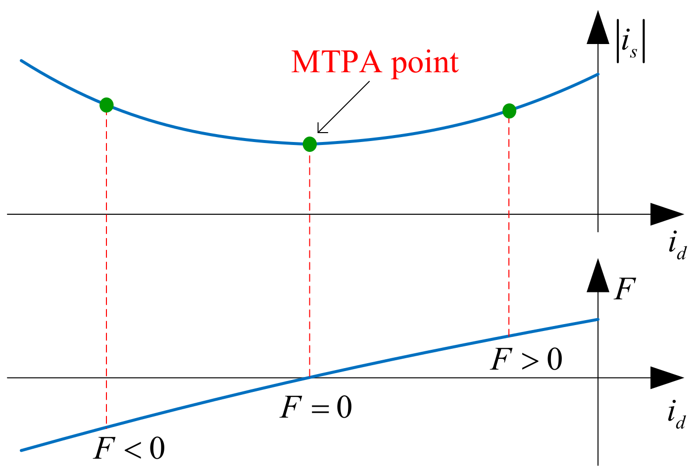
2. MTPA Indicator
3. Proposed MTPA Control Method Based on PRFS Signal Injection
3.1. PRFS Sinusoidal Signal for Injection
3.2. Electric Power Response Due to Signal Injection
3.3. Extraction of MTPA Indicator Information
3.4. Implementation of the Proposed MTPA Control Scheme
3.5. Current Control Loop Considering PRFS Signal Injection
4. Experimental Results
5. Conclusions
Author Contributions
Funding
Institutional Review Board Statement
Informed Consent Statement
Data Availability Statement
Acknowledgments
Conflicts of Interest
References
- Wang, C.S.; Guo, C.W.C.; Tsay, D.M.; Perng, J.W. PMSM Speed Control Based on Particle Swarm Optimization and Deep Deterministic Policy Gradient under Load Disturbance. Machines 2021, 9, 343. [Google Scholar] [CrossRef]
- Hezzi, A.; Elghali, S.B.; Bensalem, Y.; Zhou, Z.; Benbouzid, M.; Abdelkrim, M.N. ADRC-Based Robust and Resilient Control of a 5-Phase PMSM Driven Electric Vehicle. Machines 2020, 8, 17. [Google Scholar] [CrossRef]
- Ni, R.; Xu, D.; Wang, G.; Li, D.; Zhang, G.; Qu, L. Maximum Efficiency per Ampere Control of Permanent-Magnet Synchronous Machines. IEEE Trans. Ind. Electron. 2015, 62, 2135–2143. [Google Scholar] [CrossRef]
- Hang, J.; Wu, H.; Ding, S.; Huang, Y.; Hua, W. Improved Loss Minimization Control for IPMSM Using Equivalent Conversion Method. IEEE Trans. Power Electron. 2021, 36, 1931–1940. [Google Scholar] [CrossRef]
- Sun, J.; Lin, C.; Xing, J.; Jiang, X. Online MTPA Trajectory Tracking of IPMSM Based on a Novel Torque Control Strategy. Energies 2019, 12, 3261. [Google Scholar] [CrossRef] [Green Version]
- Dianov, A.; Tinazzi, F.; Calligaro, S.; Bolognani, S. Review and Classification of MTPA Control Algorithms for Synchronous Motors. IEEE Trans. Power Electron. 2022, 37, 3990–4007. [Google Scholar] [CrossRef]
- Lin, F.J.; Liao, Y.H.; Lin, J.R.; Lin, W.T. Interior Permanent Magnet Synchronous Motor Drive System with Machine Learning-Based Maximum Torque per Ampere and Flux-Weakening Control. Energies 2021, 14, 346. [Google Scholar] [CrossRef]
- Cao, M.; Egashira, J.; Kaneko, K. High Efficiency Control of IPMSM for Electric Motorcycles. In Proceedings of the IEEE 6th International Power Electronics and Motion Control Conference (IPEMC), Wuhan, China, 17–20 May 2009. [Google Scholar]
- Wang, G.; Li, Z.; Zhang, G.; Yu, Y.; Xu, D. Quadrature PLL-Based High-Order Sliding-Mode Observer for IPMSM Sensorless Control with Online MTPA Control Strategy. IEEE Trans. Energy Convers. 2013, 28, 214–224. [Google Scholar] [CrossRef]
- Xia, Z.; Nalakath, S.; Tarvirdilu Asl, R.; Sun, Y.; Wiseman, J.; Emadi, A. Online Optimal Tracking Method for Interior Permanent Magnet Machines with Improved MTPA and MTPV in Whole Speed and Torque Ranges. IEEE Trans. Power Electron. 2020, 35, 9753–9769. [Google Scholar] [CrossRef]
- Shinohara, A.; Inoue, Y.; Morimoto, S.; Sanada, M. Direct Calculation Method of Reference Flux Linkage for Maximum Torque per Ampere Control in DTC-Based IPMSM Drives. IEEE Trans. Power Electron. 2017, 32, 2114–2122. [Google Scholar] [CrossRef]
- Jung, S.Y.; Hong, J.; Nam, K. Current Minimizing Torque Control of the IPMSM Using Ferrari’s Method. IEEE Trans. Power Electron. 2013, 28, 5603–5617. [Google Scholar] [CrossRef]
- Mohamed, Y.A.R.I.; Lee, T.K. Adaptive Self-Tuning MTPA Vector Controller for IPMSM Drive System. IEEE Trans. Energy Convers. 2006, 21, 636–644. [Google Scholar] [CrossRef]
- Sun, T.; Koc, M.; Wang, J. MTPA Control of IPMSM Drives Based on Virtual Signal Injection Considering Machine Parameter Variations. IEEE Trans. Ind. Electron. 2018, 65, 6089–6098. [Google Scholar] [CrossRef] [Green Version]
- Li, K.; Wang, Y. Maximum Torque per Ampere (MTPA) Control for IPMSM Drives Based on a Variable-Equivalent-Parameter MTPA Control Law. IEEE Trans. Power Electron. 2019, 34, 7092–7102. [Google Scholar] [CrossRef]
- Bolognani, S.; Petrella, R.; Prearo, A.; Sgarbossa, L. Automatic Tracking of MTPA Trajectory in IPM Motor Drives Based on AC Current Injection. IEEE Trans. Ind. Appl. 2011, 47, 105–114. [Google Scholar] [CrossRef]
- Lai, C.; Feng, G.; Mukherjee, K.; Tjong, J.; Kar, N.C. Maximum Torque per Ampere Control for IPMSM Using Gradient Descent Algorithm Based on Measured Speed Harmonics. IEEE Trans. Ind. Inform. 2018, 14, 1424–1435. [Google Scholar] [CrossRef]
- Antonello, R.; Carraro, M.; Zigliotto, M. Maximum-Torque-per-Ampere Operation of Anisotropic Synchronous Permanent-Magnet Motors Based on Extremum Seeking Control. IEEE Trans. Ind. Electron. 2014, 61, 5086–5093. [Google Scholar] [CrossRef]
- Kim, S.; Yoon, Y.D.; Sul, S.K.; Ide, K. Maximum Torque per Ampere (MTPA) Control of an IPM Machine Based on Signal Injection Considering Inductance Saturation. IEEE Trans. Power Electron. 2013, 28, 488–497. [Google Scholar] [CrossRef]
- Liu, G.; Wang, J.; Zhao, W.; Chen, Q. A Novel MTPA Control Strategy for IPMSM Drives by Space Vector Signal Injection. IEEE Trans. Ind. Electron. 2017, 64, 9243–9252. [Google Scholar] [CrossRef]
- Li, K.; Wang, Y. Maximum Torque per Ampere (MTPA) Control for IPMSM Drives Using Signal Injection and an MTPA Control Law. IEEE Trans. Ind. Inform. 2019, 15, 5588–5598. [Google Scholar] [CrossRef]
- Wang, G.; Zhou, H.; Zhao, N.; Li, C.; Xu, D. Sensorless Control of IPMSM Drives Using a Pseudo-Random Phase-Switching Fixed-Frequency Signal Injection Scheme. IEEE Trans. Ind. Electron. 2018, 65, 7660–7671. [Google Scholar] [CrossRef]
- Sun, T.; Wang, J.; Chen, X. Maximum Torque per Ampere (MTPA) Control for Interior Permanent Magnet Synchronous Machine Drives Based on Virtual Signal Injection. IEEE Trans. Power Electron. 2015, 30, 5036–5045. [Google Scholar] [CrossRef]
- Sun, T.; Wang, J.; Koc, M. Self-Learning Direct Flux Vector Control of Interior Permanent-Magnet Machine Drives. IEEE Trans. Power Electron. 2017, 32, 4652–4662. [Google Scholar] [CrossRef]
- Wang, J.; Huang, X.; Yu, D.; Chen, Y.; Zhang, J.; Niu, F.; Fang, Y.; Cao, W.; Zhang, H. An Accurate Virtual Signal Injection Control of MTPA for an IPMSM with Fast Dynamic Response. IEEE Trans. Power Electron. 2018, 33, 7916–7926. [Google Scholar] [CrossRef] [Green Version]
- Chen, Q.; Zhao, W.; Liu, G.; Lin, Z. Extension of Virtual-Signal-Injection-Based MTPA Control for Five-Phase IPMSM into Fault-Tolerant Operation. IEEE Trans. Ind. Electron. 2019, 66, 944–955. [Google Scholar] [CrossRef]
- Sun, T.; Long, L.; Yang, R.; Li, K.; Liang, J. Extended Virtual Signal Injection Control for MTPA Operation of IPMSM Drives with Online Derivative Term Estimation. IEEE Trans. Power Electron. 2021, 36, 10602–10611. [Google Scholar] [CrossRef]
- Marsaglia, G. Xorshift RNGs. J. Stat. Softw. 2003, 8, 1–6. [Google Scholar] [CrossRef]
- Zhang, G.; Xiang, R.; Wang, G.; Li, C.; Bi, G.; Zhao, N.; Xu, D. Hybrid Pseudorandom Signal Injection for Position Sensorless SynRM Drives with Acoustic Noise Reduction. IEEE Trans. Transport. Electrif. 2021, in press. [Google Scholar] [CrossRef]
- Li, C.; Wang, G.; Zhang, G.; Zhao, N.; Xu, D. Adaptive Pseudorandom High-Frequency Square-Wave Voltage Injection Based Sensorless Control for SynRM Drives. IEEE Trans. Power Electron. 2021, 36, 3200–3210. [Google Scholar] [CrossRef]


| Items | Values |
|---|---|
| Rated power | 4 kW |
| Rated torque | 38 N·m |
| Rated speed | 1000 r/min |
| Rated current | 40 A |
| Number of pole pairs | 4 |
| Stator resistance | 0.08 Ω |
| Permanent magnet flux linkage | 0.14 Wb |
| d-q axis inductances | 2.3/3.8 mH |
Publisher’s Note: MDPI stays neutral with regard to jurisdictional claims in published maps and institutional affiliations. |
© 2022 by the authors. Licensee MDPI, Basel, Switzerland. This article is an open access article distributed under the terms and conditions of the Creative Commons Attribution (CC BY) license (https://creativecommons.org/licenses/by/4.0/).
Share and Cite
Li, K.; Sun, T.; Jiang, F.; Feng, W.; Li, H. MTPA Control for IPMSM Drives Based on Pseudorandom Frequency-Switching Sinusoidal Signal Injection. Machines 2022, 10, 231. https://doi.org/10.3390/machines10040231
Li K, Sun T, Jiang F, Feng W, Li H. MTPA Control for IPMSM Drives Based on Pseudorandom Frequency-Switching Sinusoidal Signal Injection. Machines. 2022; 10(4):231. https://doi.org/10.3390/machines10040231
Chicago/Turabian StyleLi, Ke, Tianfu Sun, Fucheng Jiang, Wei Feng, and Huiyun Li. 2022. "MTPA Control for IPMSM Drives Based on Pseudorandom Frequency-Switching Sinusoidal Signal Injection" Machines 10, no. 4: 231. https://doi.org/10.3390/machines10040231