Article

Fault Diagnosis of Rolling Element Bearings Based on Adaptive Mode Extraction

1
College of Mechanical and Electrical Engineering, Central South University, Changsha 410083, China
2
Light Alloy Research Institute, Central South University, Changsha 410083, China
*
Author to whom correspondence should be addressed.
Machines 2022, 10(4), 260; https://doi.org/10.3390/machines10040260
Submission received: 7 March 2022 / Revised: 30 March 2022 / Accepted: 2 April 2022 / Published: 5 April 2022
(This article belongs to the Section Machines Testing and Maintenance)

Abstract

:
Generally speaking, vibration signals collected by sensors always contain complex frequency components, which will bring great trouble to bearing condition monitoring and fault diagnosis. A reliable fault signal component extraction method is significant to detect the fault-induced weak repetitive transients. Therefore, many signal decomposition or extraction methods have been developed and are widely employed in fault diagnosis. Based on the recently proposed variational mode extraction (VME) method, an adaptive optimal mode extraction method was designed with a new strategy to extract the mode center frequency and a novel indicator to optimize the balance parameter. The spectrum is first divided into several modes by enveloping curve fitting (ECF), and the center frequencies of each mode are extracted, respectively. All potential fault modes are then extracted sequentially utilizing the extracted center frequency and fixed balance parameter. For the extracted modes, the kurtosis index is applied to select the target mode. Finally, the relative amplitude ratio (RAR) index is used to adaptively adjust the balance parameter. The comparison results reveal that the adaptive mode extraction method can extract the weak fault feature under strong interference.

1. Introduction

In rotating machinery, rolling element bearings are essential components, and the condition of bearings has a significant influence on the healthy operation of the system [1,2]. The occurrence of localized defects will generate successive quasi-periodic impulses, stimulating resonance in the rotating machinery [3]. According to the structural characteristics of rolling bearings, the pulse induced by defects in different positions also has different periods. Therefore, the frequency of impulse repetition often gives a direct indication of the fault location, and the diagnosis technique based on frequency analysis has received very much attention [4]. For the above reasons, although there are many different signals, such as acoustic emission signals [5], vibration signals are the most commonly used because the accelerometer installed near the rolling element bearing can detect impulse excitation resonance signals [6].
Many advanced signal processing techniques, including blind deconvolution [7,8,9], optimal frequency band selection [10,11,12], adaptive signal decomposition [13,14,15], machine learning [16], stochastic resonance [17,18,19], time-frequency analysis [20,21], and higher-order statistics [22], have been developed for diagnosing the incipient fault of REBs. On account of the vibration responses being a mixture of complex frequency components, signal decomposition methods are especially suitable for analyzing them. Many researchers have applied various signal decomposition methods to fault diagnosis analysis, such as empirical mode decomposition [23,24], local mean decomposition [25,26], intrinsic time-scale decomposition [27], and variational mode decomposition [28].
In these methods, variational mode decomposition (VMD) is a new signal decomposition method proposed by Dragomiretskiy and Zosso [29], which can decompose a non-stationary signal into several distinct modes. The VMD method has been applied on many occasions, such as short-term wind power forecasting [30], fault diagnosis [31,32], etc., and it has a good effect on signal decomposition and signal-to-noise ratio enhancement. However, in the VMD method, the number of the decomposed modes and the balance parameter are two parameters that have important influence on the decomposition performance and should be determined in advance. Although scholars have done a lot of work in parameter optimization, the existing methods still have low accuracy and complex operation problems to a certain extent.
In addition, in the decomposition process, VMD extracts all modes simultaneously, but in fact, there is only one meaningful mode that contains fault feature information. Thus, the process of selecting the target mode that contains the fault information may also introduce interference. To address the above problems, Jiang et al. [33] proposed an initial center frequency-guided method, which can directly extract the mode without caring about the number of decomposed modes, thus significantly enhancing the effectiveness of the VMD method. At the same time, it is pointed out in the above noted paper that the initial center frequency arbitrarily set within a reasonable range will eventually converge to the target center frequency. In [34], envelope negentropy spectrum (ENS) is used to locate the center frequency, and then target mode can be extracted based on the guidance of the initial center frequency, which further improves the performance of the VMD method. These theories and methods provide a theoretical basis for direct extraction of fault mode and point out the direction for proposing new ways.
Recently, Nazari et al. proposed a method called variational mode extraction (VME), which can directly extract the specific mode of interest [35]. This method has a similar theoretical basis as VMD, and the extracted target mode is more compact around the central frequency. The VME method has been used in biological signal processing [35], but its great application potential in bearing fault diagnosis has not been discovered.
In this paper, adaptive optimal mode extraction method based on the VME is utilized to process the bearing fault vibration signal. First, the envelope curve fitting (ECF) method is utilized to preliminarily divide the spectrum and extract all possible fault mode center frequencies. The fault mode is then determined based on the kurtosis criterion, and the relative amplitude ratio (RAR) index is used to optimize the balance parameter. Finally, the VME method utilizes the determined center frequency and balance parameter to extract the optimal fault mode and enhance the fault characteristics. In [36], Zhao et al. proposed an envelope nesting method for preliminary segmentation of vibration signals, which proved to be a practical preprocessing step of the VMD method. In this paper, we propose a mode segmentation method called envelope curve fitting (ECF), which can determine the center frequency from split mode. VME can then extract the modes that may contain fault feature information and select the mode with the maximum kurtosis as the target mode. Aiming at the insufficient stability of the kurtosis index, some new evaluation indexes are put forward. Li et al. [37] constructs a weighted kurtosis index by combining kurtosis and correlation coefficient. Yang et al. [38] proposed a SAF index to choose the optimal IMF decomposed by the EEMD method. In this paper, during the process of target mode optimization, a relative amplitude ratio (RAR) index is constructed to adaptively determine the balance parameter, and the optimal mode can be extracted directly based on the proposed method.
The main contributions of this paper are summarized as follows:
(1)
A novel adaptive mode extraction method is established based on variational mode extraction (VME) method.
(2)
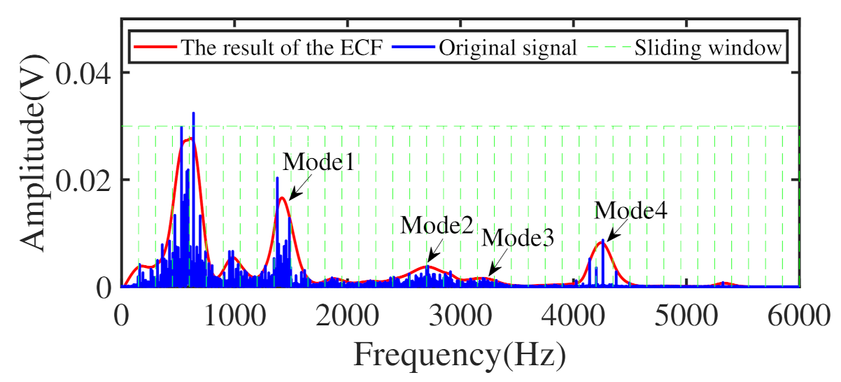
A spectrum segmentation method called envelope curve fitting (ECF) is proposed to determine the initial center frequency of the VME method, and relative amplitude ratio (RAR) index is used to optimize the balance parameter.
(3)
The proposed method has been verified on different test benches and compared with other methods, which proves the effectiveness of the proposed method.
The remainder of the paper is organized as follows. Section 2 describes the details of adaptive optimal mode extraction based on VME. The method of center frequency extraction and the new constructed evaluation index is also introduced in this section. The flow chart of the proposed method is described in Section 3. The mode optimization process and comparison experiment results are presented in Section 4. Finally, Section 5 concludes this work.

2. Underlying Theory

2.1. Basic Principle of VME

Variational mode extraction (VME) is built on the consistent basis of variational mode decomposition (VMD), and it can directly extract specific modes under the guidance of the initial central frequency, rather than all the modes, which is very attractive in fault diagnosis.
The target mode u d t extracted from the raw signal f t by VME is the optimal solution for the constrained optimization problem as follows:
min u d , w d , f r α J 1 + J 2 s . t . u d t + f r t = f t
where α is the balance parameter.
The expression J 1 is the criterion to ensure the mode compact around its center frequency w d as follows:
J 1 = t δ t + j π t u d t e j w d t 2 2 .
The expression J 2 is the rule to ensure the minimum overlap between target mode u d t and residual signal f r t as follows:
J 2 = β t f r t 2 2
where β t is the impulse response of the filter.
Like the VMD method, the augmented Lagrangian is introduced as follows:
L u d , w d , λ = α t δ t + j π t u d t e j w d t 2 2 + β t f r t 2 2 + f t u d t + f r t 2 2 + λ t , f t u d t + f r t
Target mode u ^ d n + 1 w is updated iteratively as follows:
u ^ d n + 1 w = f ^ w + α 2 w w d n + 1 4 u ^ d n w + λ ^ w 2 1 + α 2 w w d n + 1 4 1 + 2 α w w d n 2
Center frequency w d n + 1 is updated iteratively as follows:
w d n + 1 = 0 w u ^ d n + 1 w 2 d w 0 u ^ d n + 1 w 2 d w
The Lagrangian multiplier is updated iteratively as follows:
λ ^ n + 1 = λ ^ n + τ f ^ w u ^ d n + 1 w 1 + α 2 w w d n + 1 4
After the convergence condition Equation (8) is satisfied, the target mode with sufficient accuracy can be obtained.
u ^ d n + 1 u ^ d n 2 2 u ^ d n 2 2 < ε
The specific description can be referred to in [35].
As shown in [39], the Lagrange multiplier λ and update parameter τ have little influence on the accuracy of the target mode. In contrast, the initial center frequency w d and balance parameter α are the key factors to extract the target mode accurately, and special attention should be paid to setting and optimization. A large balance parameter may cause the roughly extracted mode to have large bandwidth and introduce a lot of noise. In contrast, a small balance parameter may lead to incomplete information in the extracted mode. The unreasonable initial center frequency will guide the extracted mode to converge to the interference component in the process of iteration. Therefore, the following research work mainly focuses on the reasonable selection and optimization of these two parameters.

2.2. Envelope Curve Fitting (ECF) and Relative Amplitude Ratio (RAR)

For the VME method, the initial center frequency of the mode needs to be determined in advance, and then the target mode can be extracted under the guidance of the initial center frequency. Inspired by the literature [36], this paper uses the envelope curve fitting (ECF) method to estimate possible target mode center frequencies.
First, the raw vibration signal should be transformed to the spectrum by fast Fourier transform. A sliding window with a suitable size is then created, and the size of the overlap (or interval) of adjacent windows during sliding is determined based on signal characteristics. The maximum value in each window is selected, and other values are discarded. The window was slid from left to right along the horizontal axis to obtain a series of peaks and was fitted to discard unnecessary details. Finally, the resulting curve can extract the corresponding mode center frequencies.
We utilize an outer race fault vibration signal provided by Case Western Reserve University (CWRU) to illustrate the process and results of the ECF method. Considering that the resonance frequency excited by local fault is generally higher than 1500 Hz [6], some modes can be discarded, and VME extracts only the mode with a higher central frequency. In the ECF method, the sliding window size is 150 Hz, and the interval between two adjacent windows is 0. As shown in Figure 1, after the vibration signal spectrum is processed by the ECF method, it can be found that several main modes become more evident, which is convenient to extract the center frequency.
As stated in Section 2.1, a large bandwidth may introduce additional interference, whereas a small one will lose crucial diagnostic information. Therefore, the matched mode bandwidth is also significant for selecting fault-related mode. In this paper, considering the sensitivity of the kurtosis index to random pulse, the relative amplitude ratio (RAR) index is used to optimize the balance parameter. In amplitude spectrum, RAR can be represented as the relative value of the fault frequency band and the frequency with a maximum amplitude outside the fault frequency band. The index is denoted as follows:
RAR = n = f f a u l t Δ f f a u l t + Δ T n T f i
where T n denotes Fourier transform amplitude spectrum, f f a u l t denotes the fault characteristic frequency, Δ is the boundary of the actual fault frequency deviated from the theoretical fault frequency, and f i is the frequency with a maximum amplitude outside the fault frequency band.
To illustrate the necessity of using the RAR index, we employ the kurtosis and RAR index to optimize the balance parameter, and the results are shown in Figure 2. The ball fault vibration signal is provided by Case Western Reserve University (CWRU). When kurtosis is used as the evaluation index, as demonstrated in Figure 2a,b, the target mode reaches the optimal state when the balance parameter is 300, and there are some noticeable interference frequencies. However, as illustrated in Figure 2c,d, the optimization curve of RAR is entirely different from the previous result, and the target frequency is very prominent in the envelope spectrum. This evidence indicates that the constructed evaluation index can effectively optimize the balance parameter, and with it, the VME method can detect the fault feature from a contaminated signal. In addition, VME can avoid the problem that the mode is segmented by mistake and retain all fault feature information to the maximum extent.

3. The Flow Chart of the Proposed Method

The flow chart of the adaptive optimal mode extraction method is illustrated in Figure 3, as described in the following concrete steps:
(1)
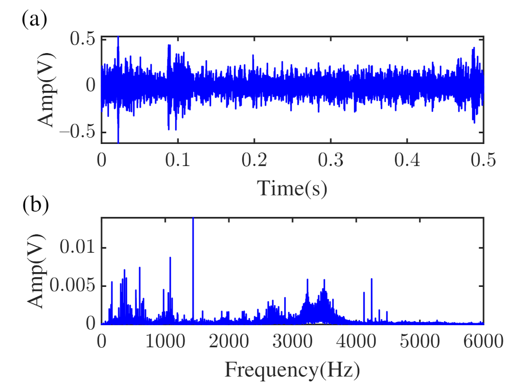
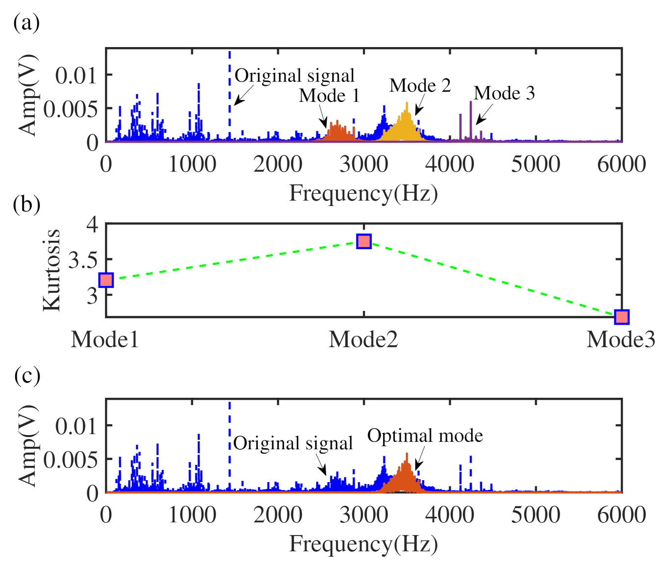
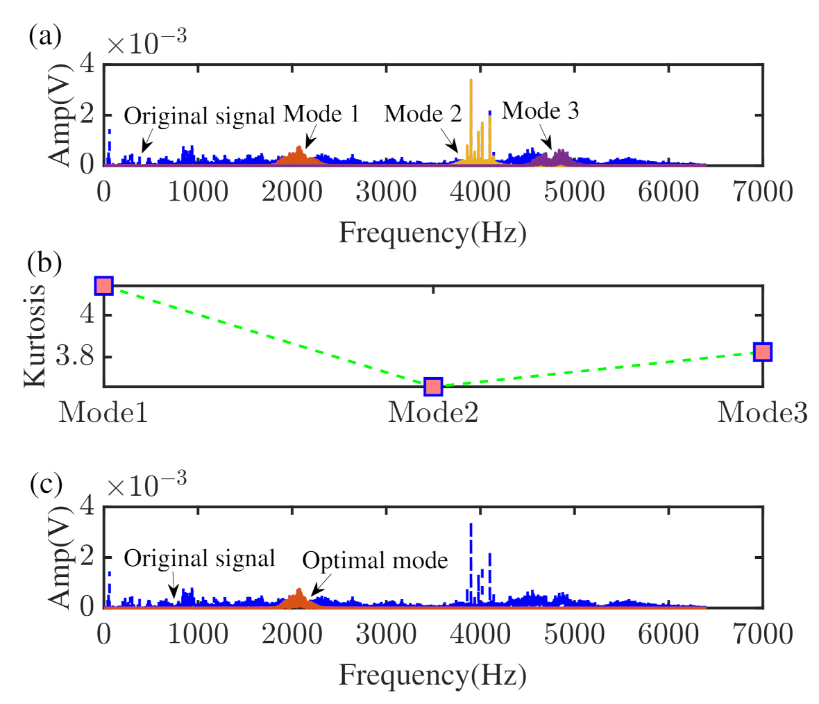
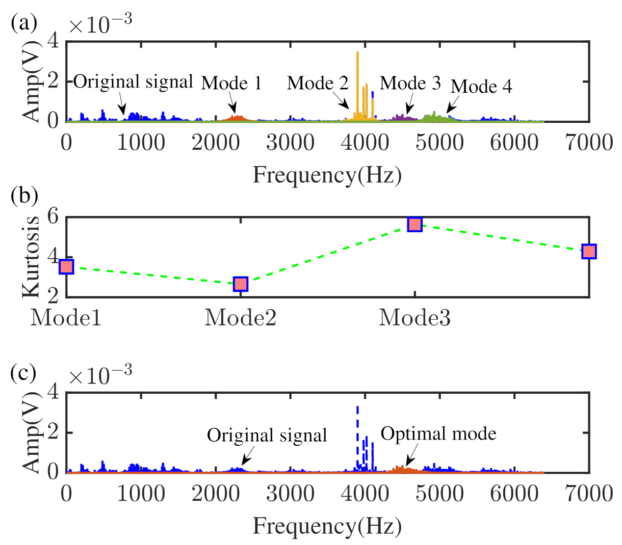
Obtain the mode containing fault feature information. First, ECF is performed on the collected vibration data to obtain the center frequencies of principal modes above 1500 Hz. Next, with a fixed balance parameter, VME is used to extract modes that may contain fault feature information and choose the mode with the highest kurtosis value as the target mode.
(2)
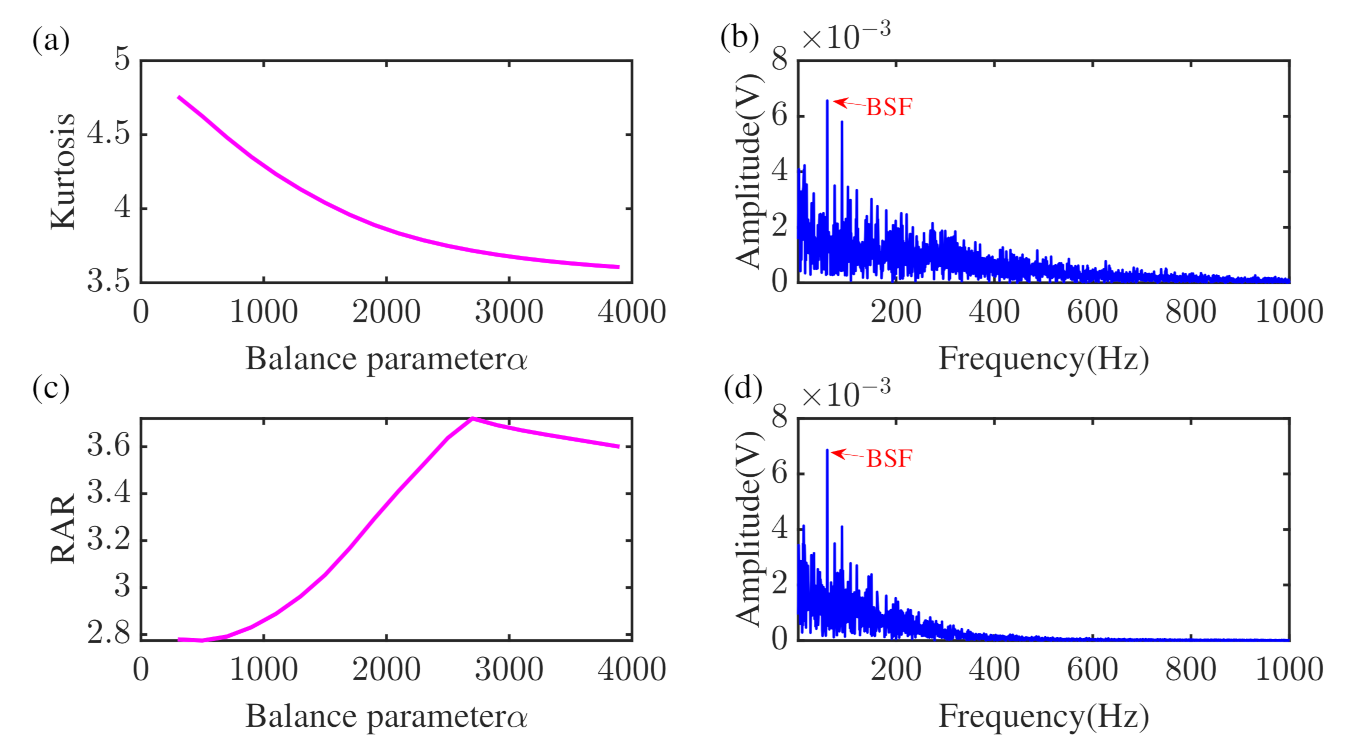
Target mode optimization. The balance parameter is adjusted by maximizing the RAR index to obtain the optimal mode.
(3)
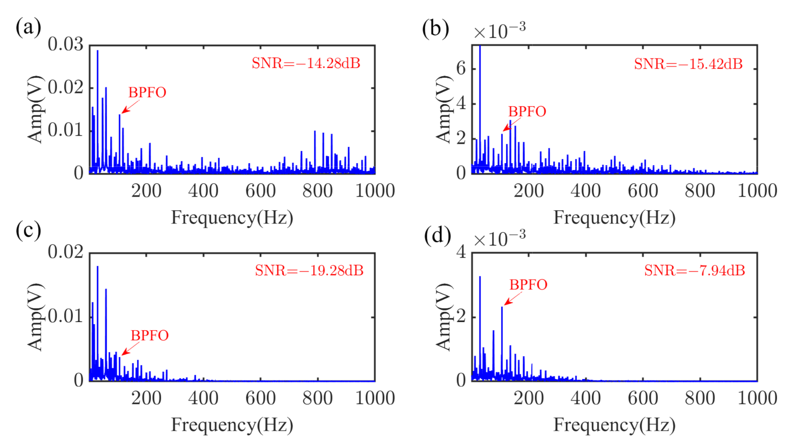
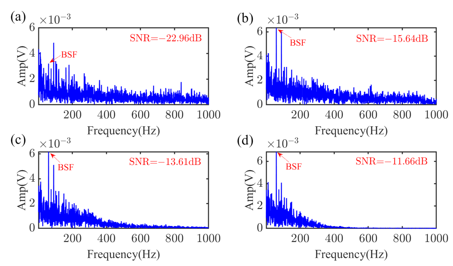
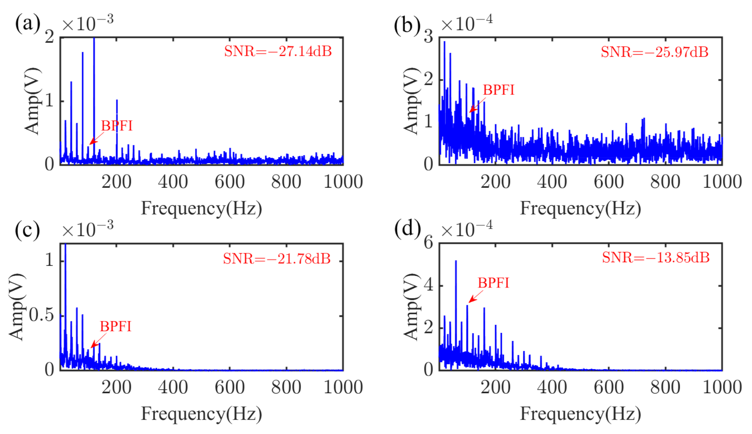
Hilbert envelope demodulation. Demodulate the mode from the adaptive VME method and identify the practical fault characteristic frequency.
(4)
Fault diagnosis. The machine health state is judged by identifying the fault characteristic frequency.

4. Experimental Verification

4.1. The Rolling Element Bearings Data from CWRU

In this section, data from Case Western Reserve University (CWRU) Bearings Data Center [40] were used to test the validity of the adaptive mode extraction method.
Figure 4 is the CWRU bearing test rig. The test rig is composed of a 2 hp motor, a dynamometer, a torque transducer/encoder, and control electronics. The faulty bearings tested were installed at the fan or drive end to support the motor shaft, and the bearings type are SKF 6205-2RS JEM and SKF 6205-2RS JEM, respectively. The diameters of the outer race fault and rolling element fault are 0.021 and 0.007 , respectively. Vibration signal was gathered by accelerometers, and the sampling rate was 12 kHz. The theoretical fault characteristic frequency of bearing outer race fault (BPFO) was 105.9 Hz, and the ball spin frequency (BSF) was 59.7 Hz.
First, the bearing outer race fault signal is used to confirm the effectiveness of the adaptive mode extraction method. In this paper, data with a total length of 0.5 s were selected for analysis.
Figure 5 shows the waveform and the frequency spectrum from which fault-related information can barely be found. The proposed method is then performed to process the defective signal, and the optimization procedure and results are illustrated in Figure 6a–c. The third mode with the largest kurtosis value is chosen as the target mode.
Some comparative results are given in Figure 7 to demonstrate the effectiveness of the adaptive optimal mode extraction method. The envelope spectrum of the original data is provided in Figure 7a, and the SNR is −14.28 dB. The BPFO in the envelope spectrum can be discovered, but the low-frequency noise interference is apparent. The band-pass filter with bandwidth [2500–4000 Hz] is utilized to obtain the frequency band, which contains fault feature information. The magnitude of the BPFO in Figure 7b is less than that in Figure 7a, and the SNR also decreased from −14.28 dB to −15.42 dB. As shown in Figure 7c, a mode with the largest kurtosis value is selected from the VMD decomposition results, but the target frequency is barely detected. The proposed adaptive optimal mode extraction method result is shown in Figure 7d. Although the rotating frequency is prominent, the BPFO can be easily identified. The SNR also confirms that the proposed method effectively extracts weak fault features.
The rolling element defective data were then analyzed. The noise components are so strong that the fault-induced impulse responses cannot be identified in Figure 8. Three modes that may contain weak repetitive transients information are extracted, and then the second mode is further optimized by the RAR index. The results are provided in Figure 9a–c and according to the analysis results, the optimal mode contains abundant fault information.
In the envelope spectrum exhibited in Figure 10a, the target frequency can be pointed out, but the SNR is low (−22.96 dB). The band-pass filter with bandwidth [2500–4000 Hz] and the VMD method are both applied, and the results are shown in Figure 10b,c, respectively. It can be found that high-frequency interference components have been suppressed, but some noise near the BSF is significant. The result processed by the adaptive mode extraction method is illustrated in Figure 10d. It indicates that a fault-related feature is prominent, and the interference frequency around them is significantly suppressed. It should be noticed that the SNR increases from −22.96 dB to −11.66 dB, which is conducive to fault diagnosis of rotating machines.

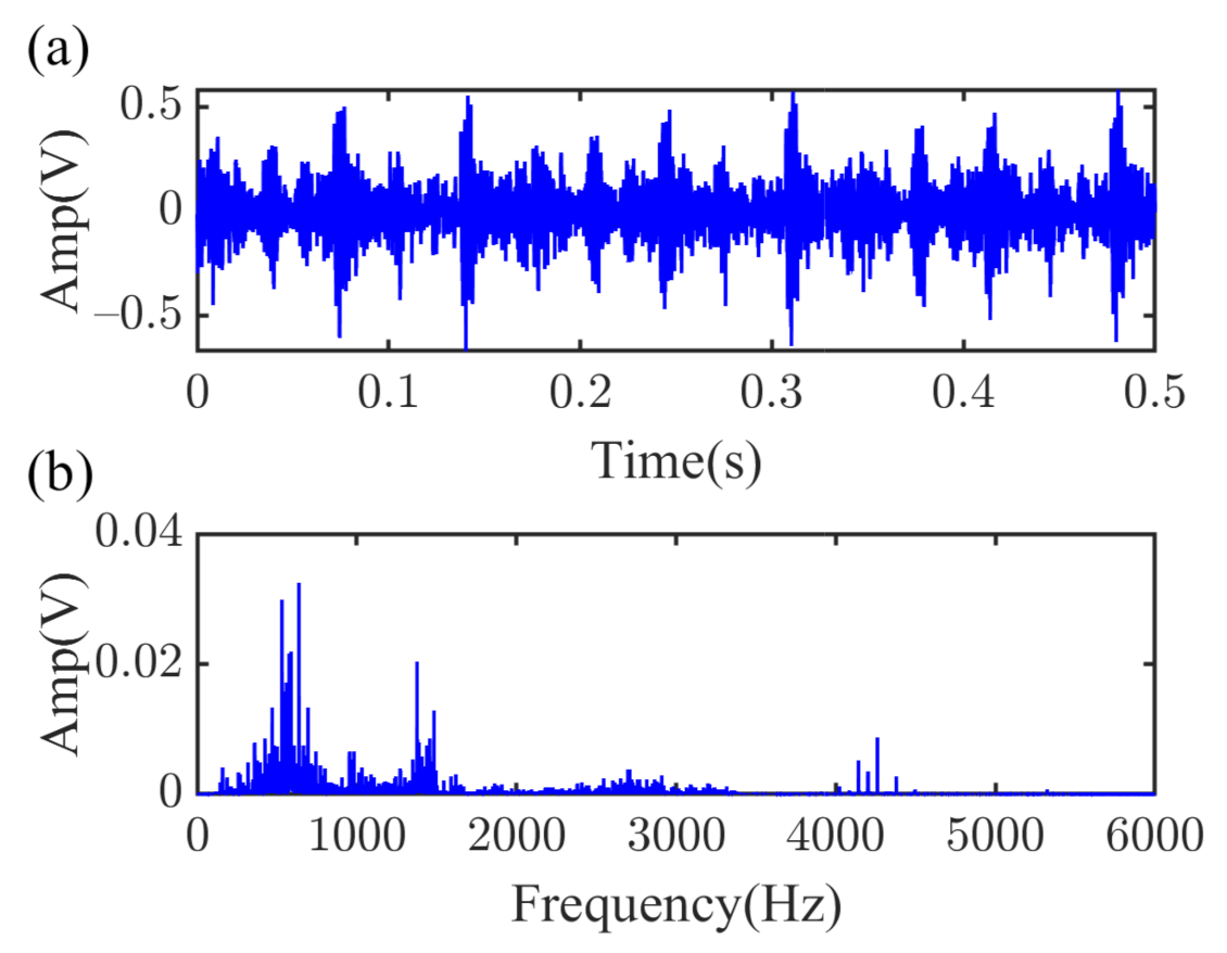
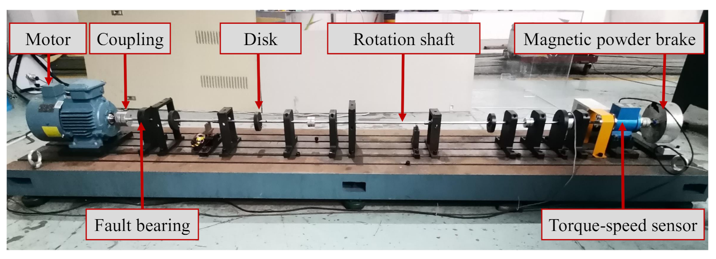
4.2. Vibration Data Collected from TRDT Test Stand

The experimental data collected from the tail rotor drive train (TRDT) test stand were adopted to further validate the practicability of the adaptive optimal mode extraction method.
The structure of the TRDT test stand is shown in Figure 11. As displayed in Figure 11, the test stand consists of a AC motor, several couplings, rotation shaft, disks, etc. Single point faults were introduced to the test bearings to simulate the pitting fault of bearings. Vibration data were collected using accelerometers, which were attached to the housing. The acceleration sensor is a uniaxial accelerometer, model PCB 352C33. The vibration data acquisition equipment uses cDAQ 9188 and 9220 from National Instruments (NI) Inc. The LabVIEW is used to record the raw data. The sampling rate of the vibration signal was 12,800 Hz, and the shaft rotation speed was 1200 r/min. The fault bearings 6200 is a deep-groove ball bearing, and the specific parameters are listed in Table 1.
The waveform of the outer raceway fault data and its corresponding spectrum are illustrated in Figure 12. There is no apparent periodic pulse and fault characteristic information displayed in the spectrum. Several modes extracted by the VME method are shown in Figure 13. According to the analysis results, mode 1 is determined as the target mode, and RAR is used for further optimization.
Some interference components around the BFPO and weak fault characteristic information are hard to find in the original signal, as confirmed in Figure 14a. It is obvious that reliable diagnosis results cannot be obtained. By employing the band-pass filter with bandwidth [1500–3500 Hz], the envelope spectrum result is exhibited in Figure 14b, in which the BPFO has been enhanced, and the SNR increases from −19.51 dB to −14.28 dB as compared to Figure 14a. Because of fault information splitting or mode selection error, no valid fault information was extracted by the VMD method, as confirmed in Figure 14c. The result from the proposed method is exhibited in Figure 14d. The SNR is calculated as −11.12 dB, which is higher than that of the band-pass filter. The BPFO and its harmonics are distinct. With the analysis result, a reliable conclusion can be drawn that there is a local defect on the outer raceway of the bearing.
Finally, the proposed method is used to analyze the signal of bearing inner race fault. The practical vibration signal of inner race fault and corresponding Fourier spectrum are shown in Figure 15, in which critical fault frequency components are buried in strong noise.
According to the kurtosis value in Figure 16, mode 3 is selected as the target mode among the four modes extracted from the VME method. The envelope spectrum result of the raw signal is presented in Figure 17a, in which the magnitude of BPFI is so small that it is difficult to be identified. As demonstrated in Figure 17b, the envelope analysis is applied to the signal, which is filtered by the band-pass filter with bandwidth [1500–3500 Hz]. It should be noted that the interference is significantly attenuated, and the fault-related characteristic frequency is enhanced, which is also confirmed by the SNR. As declared in the introduction above, improper parameters can seriously reduce the effectiveness of the VMD method, and it may not even be able to extract any beneficial fault-related characteristics as performed in Figure 17c. The proposed method is applied to the collected signal, and the result is shown in Figure 17d. It can be found that although the rotational frequency can still be observed, the fault characteristic frequency has been dramatically enhanced, and the SNR is increased to −13.85 dB. There is no doubt that the adaptive optimal mode extraction method can effectively extract features for the inner raceway defective diagnosis.

5. Conclusions

In this paper, an adaptive mode extraction method is proposed for fault diagnosis of REBs. In the proposed method, a new tool, i.e., the envelope curve fitting (ECF), is developed to estimate the initial center frequencies of possible target modes. This tool is then fused with VME for extracting discrete modes. For the target mode, the balance parameter of VME is adaptively optimized by the relative amplitude ratio (RAR) index. From the analysis results of experimental cases, it can be discovered that the kurtosis index is easily affected by random noise when optimizing the balance parameter, which hinders the accuracy of fault mode extraction. In contrast, with the support of the RAR index, the proposed adaptive mode extraction method can accurately identify the optimal balance parameter. The comparative results prove that the proposed adaptive mode extraction method is a reliable method to identify the fault of REBs, even in the presence of strong noise.
In this paper, bearing fault diagnosis is only considered under constant speed, and its applicability under variable speed has not been verified, so therefore needs to be further discussed in future studies.

Author Contributions

Methodology, C.L.; conceptualization, C.L.; formal analysis, J.T.; investigation, J.T.; resources, J.T.; software, C.L. and Z.H.; validation, C.L.; data curation, C.L.; writing—original draft preparation, C.L.; writing—review and editing, J.T. and Z.H.; supervision, J.T.; project administration, J.T.; funding acquisition, C.L. and J.T. All authors have read and agreed to the published version of the manuscript.

Funding

This work was supported by the National Key R&D Program of China (2018AAA0101703) and the Fundamental Research Funds for the Central Universities of Central South University.

Institutional Review Board Statement

Not applicable.

Informed Consent Statement

Not applicable.

Data Availability Statement

Data presented in this study are available in this article.

Acknowledgments

We would like to thank Case Western Reserve University (CWRU) Bearings Data Center for providing the dataset.

Conflicts of Interest

The authors declare no conflict of interest.

Abbreviations

The following abbreviations are used in this manuscript:
VMEVariational Mode Extraction
VMDVariational Mode Decomposition
ECFEnvelope Curve Fitting
RARRelative Amplitude Ratio
CWRUCase Western Reserve University
TRDTTail Rotor Drive Train
BPFIBall Pass Frequency, Inner Race
BPFOBall Pass Frequency, Outer Race
BSFBall (Roller) Spin Frequency

References

  1. Randall, R.B.; Antoni, J. Rolling element bearing diagnostics—A tutorial. Mech. Syst. Signal Process. 2011, 25, 485–520. [Google Scholar] [CrossRef]
  2. Duan, Z.; Wu, T.; Guo, S.; Shao, T.; Malekian, R.; Li, Z. Development and trend of condition monitoring and fault diagnosis of multi-sensors information fusion for rolling bearings: A review. Int. J. Adv. Manuf. Technol. 2018, 96, 803–819. [Google Scholar] [CrossRef] [Green Version]
  3. Cong, F.; Chen, J.; Dong, G.; Pecht, M. Vibration model of rolling element bearings in a rotor-bearing system for fault diagnosis. J. Sound Vib. 2013, 332, 2081–2097. [Google Scholar] [CrossRef]
  4. Zhang, B.; Miao, Y.; Lin, J.; Li, H. Weighted envelope spectrum based on the spectral coherence for bearing diagnosis. ISA Trans. 2021. [Google Scholar] [CrossRef] [PubMed]
  5. Liu, Z.; Yang, B.; Wang, X.; Zhang, L. Acoustic emission analysis for wind turbine blade bearing fault detection under time-varying low-speed and heavy blade load conditions. IEEE Trans. Ind. Appl. 2021, 57, 2791–2800. [Google Scholar] [CrossRef]
  6. Golafshan, R.; Sanliturk, K.Y. Svd and hankel matrix based de-noising approach for ball bearing fault detection and its assessment using artificial faults. Mech. Syst. Signal Process. 2016, 70–71, 36–50. [Google Scholar] [CrossRef]
  7. Miao, Y.; Wang, J.; Zhang, B.; Li, H. Practical framework of gini index in the application of machinery fault feature extraction. Mech. Syst. Signal Process. 2022, 165, 108333. [Google Scholar] [CrossRef]
  8. Zhou, Q.; Zhang, Y.; Tang, J.; Lin, J.; He, L.; Yi, C. Blind deconvolution technique based on improved correlated generalized lp/lq norm for extracting repetitive transient feature. IEEE Trans. Instrum. Meas. 2021, 70, 1–21. [Google Scholar] [CrossRef]
  9. Wang, Z.; Zhou, J.; Du, W.; Lei, Y.; Wang, J. Bearing fault diagnosis method based on adaptive maximum cyclostationarity blind deconvolution. Mech. Syst. Signal Process. 2022, 162, 108018. [Google Scholar] [CrossRef]
  10. Ni, Q.; Ji, J.; Feng, K.; Halkon, B. A novel correntropy-based band selection method for the fault diagnosis of bearings under fault-irrelevant impulsive and cyclostationary interferences. Mech. Syst. Signal Process. 2021, 153, 107498. [Google Scholar] [CrossRef]
  11. Schmidt, S.; Gryllias, K.C. Combining an optimisation-based frequency band identification method with historical data for novelty detection under time-varying operating conditions. Measurement 2021, 169, 108517. [Google Scholar] [CrossRef]
  12. Schmidt, S.; Mauricio, A.; Heyns, P.S.; Gryllias, K.C. A methodology for identifying information rich frequency bands for diagnostics of mechanical components-of-interest under time-varying operating conditions. Mech. Syst. Signal Process. 2020, 142, 106739. [Google Scholar] [CrossRef]
  13. Zhou, W.; Feng, Z.; Xu, Y.; Wang, X.; Lv, H. Empirical fourier decomposition: An accurate signal decomposition method for nonlinear and non-stationary time series analysis. Mech. Syst. Signal Process. 2022, 163, 108155. [Google Scholar] [CrossRef]
  14. He, X.; Zhou, X.; Yu, W.; Hou, Y.; Mechefske, C.K. Adaptive variational mode decomposition and its application to multi-fault detection using mechanical vibration signals. ISA Trans. 2021, 111, 360–375. [Google Scholar] [CrossRef] [PubMed]
  15. Li, J.; Cheng, X.; Li, Q.; Meng, Z. Adaptive energy-constrained variational mode decomposition based on spectrum segmentation and its application in fault detection of rolling bearing. Signal Process. 2021, 183, 108025. [Google Scholar] [CrossRef]
  16. Cheng, H.; Kong, X.; Chen, G.; Wang, Q.; Wang, R. Transferable convolutional neural network based remaining useful life prediction of bearing under multiple failure behaviors. Measurement 2021, 168, 108286. [Google Scholar] [CrossRef]
  17. Lu, S.; He, Q.; Wang, J. A review of stochastic resonance in rotating machine fault detection. Mech. Syst. Signal Process. 2018, 116, 230–260. [Google Scholar] [CrossRef]
  18. Chen, X.H.; Cheng, G.; Shan, X.L.; Hu, X.; Guo, Q.; Liu, H.G. Research of weak fault feature information extraction of planetary gear based on ensemble empirical mode decomposition and adaptive stochastic resonance. Measurement 2015, 73, 55–67. [Google Scholar] [CrossRef]
  19. Li, J.; Li, M.; Zhang, J. Rolling bearing fault diagnosis based on time-delayed feedback monostable stochastic resonance and adaptive minimum entropy deconvolution. J. Sound Vib. 2017, 401, 139–151. [Google Scholar] [CrossRef]
  20. Dhamande, L.S.; Chaudhari, M.B. Compound gear-bearing fault feature extraction using statistical features based on time-frequency method. Measurement 2018, 125, 63–77. [Google Scholar] [CrossRef]
  21. Feng, Z.; Liang, M.; Chu, F. Recent advances in time–frequency analysis methods for machinery fault diagnosis: A review with application examples. Mech. Syst. Signal Process. 2013, 38, 165–205. [Google Scholar] [CrossRef]
  22. Dong, G.; Chen, J.; Zhao, F. A frequency-shifted bispectrum for rolling element bearing diagnosis. J. Sound Vib. 2015, 339, 396–418. [Google Scholar] [CrossRef]
  23. Chen, B.; Yin, P.; Gao, Y.; Peng, F. Use of the correlated eemd and time-spectral kurtosis for bearing defect detection under large speed variation—Sciencedirect. Mech. Mach. Theory 2018, 129, 162–174. [Google Scholar] [CrossRef]
  24. Mohanty, S.; Gupta, K.K.; Raju, K.S. Hurst based vibro-acoustic feature extraction of bearing using emd and vmd. Measurement 2017, 117, 200–220. [Google Scholar] [CrossRef]
  25. Li, Y.; Xu, M.; Wang, R.; Huang, W. A fault diagnosis scheme for rolling bearing based on local mean decomposition and improved multiscale fuzzy entropy. J. Sound Vib. 2016, 360, 277–299. [Google Scholar] [CrossRef]
  26. Sun, J.; Xiao, Q.; Wen, J.; Zhang, Y. Natural gas pipeline leak aperture identification and location based on local mean decomposition analysis. Measurement 2016, 79, 147–157. [Google Scholar] [CrossRef]
  27. Yang, Y.; Pan, H.; Ma, L.; Cheng, J. A roller bearing fault diagnosis method based on the improved itd and rrvpmcd. Measurement 2014, 55, 255–264. [Google Scholar] [CrossRef]
  28. He, D.; Liu, C.; Jin, Z.; Ma, R.; Chen, Y.; Shan, S. Fault diagnosis of flywheel bearing based on parameter optimization variational mode decomposition energy entropy and deep learning. Energy 2022, 239, 122108. [Google Scholar] [CrossRef]
  29. Dragomiretskiy, K.; Zosso, D. Variational mode decomposition. IEEE Trans. Signal Process. 2013, 62, 531–544. [Google Scholar] [CrossRef]
  30. Duan, J.; Wang, P.; Ma, W.; Tian, X.; Fang, S.; Cheng, Y.; Chang, Y.; Liu, H. Short-term wind power forecasting using the hybrid model of improved variational mode decomposition and correntropy long short-term memory neural network. Energy 2021, 214, 118980. [Google Scholar] [CrossRef]
  31. Li, H.; Liu, T.; Wu, X.; Chen, Q. An optimized vmd method and its applications in bearing fault diagnosis. Measurement 2020, 166, 108185. [Google Scholar] [CrossRef]
  32. Chen, G.; Yan, C.; Meng, J.; Wang, H.; Wu, L. Improved vmd-frft based on initial center frequency for early fault diagnosis of rolling element bearing. Meas. Sci. Technol. 2021, 32, 115024. [Google Scholar] [CrossRef]
  33. Jiang, X.; Shen, C.; Shi, J.; Zhu, Z. Initial center frequency-guided vmd for fault diagnosis of rotating machines. J. Sound Vib. 2018, 435, 36–55. [Google Scholar] [CrossRef]
  34. Wang, H.; Jiang, X.; Guo, W.; Shi, J.; Zhu, Z. An enhanced vmd with the guidance of envelope negentropy spectrum for bearing fault diagnosis. Complexity 2020, 2020, 5162916. [Google Scholar] [CrossRef]
  35. Nazari, M.; Sakhaei, S.M. Variational mode extraction: A new efficient method to derive respiratory signals from ecg. IEEE J. Biomed. Health Inform. 2017, 22, 1059–1067. [Google Scholar] [CrossRef]
  36. Zhao, Y.; Li, C.; Fu, W.; Liu, J.; Chen, H. A modified variational mode decomposition method based on envelope nesting and multi-criteria evaluation. J. Sound Vib. 2019, 468, 115099. [Google Scholar] [CrossRef]
  37. Li, J.; Chen, X.; He, Z. Adaptive stochastic resonance method for impact signal detection based on sliding window. Mech. Syst. Signal Process. 2013, 36, 240–255. [Google Scholar] [CrossRef]
  38. Yang, J.; Huang, D.; Zhou, D.; Liu, H. Optimal imf selection and unknown fault feature extraction for rolling bearings with different defect modes. Measurement 2020, 157, 107660. [Google Scholar] [CrossRef]
  39. Pang, B.; Nazari, M.; Tang, G. Recursive variational mode extraction and its application in rolling bearing fault diagnosis. Mech. Syst. Signal Process. 2022, 165, 108321. [Google Scholar] [CrossRef]
  40. Smith, W.A.; Randall, R.B. Rolling element bearing diagnostics using the case western reserve university data: A benchmark study. Mech. Syst. Signal Process. 2015, 64–65, 100–131. [Google Scholar] [CrossRef]
Figure 1. The result of envelope curve fitting.
Machines 10 00260 g001
Figure 2. Envelope spectrum results by different evaluation indexes: (a) curve of the optimization procedure by kurtosis; (b) result optimized by kurtosis; (c) curve of the optimization procedure by RAR; (d) result optimized by RAR.
Machines 10 00260 g002
Figure 3. The flow chart of the proposed method.
Machines 10 00260 g003
Figure 4. CWRU bearing test rig.
Machines 10 00260 g004
Figure 5. Vibration signal of outer race defective bearing: (a) time waveform; (b) Fourier spectrum.
Machines 10 00260 g005
Figure 6. Extraction result by the proposed method: (a) extracted modes; (b) the kurtosis of different modes; (c) the optimal target mode.
Machines 10 00260 g006
Figure 7. Envelope spectrum analysis results: (a) original signal; (b) band-pass filter; (c) VMD; (d) the proposed method.
Machines 10 00260 g007
Figure 8. Vibration signal of rolling element defective bearing: (a) time waveform; (b) Fourier spectrum.
Machines 10 00260 g008
Figure 9. Extraction result by the proposed method: (a) extracted modes; (b) the kurtosis of different modes; (c) the optimal target mode.
Machines 10 00260 g009
Figure 10. Envelope spectrum analysis results: (a) original signal; (b) band-pass filter; (c) VMD; (d) the proposed method.
Machines 10 00260 g010
Figure 11. Tail rotor drive train test stand.
Machines 10 00260 g011
Figure 12. Vibration signal of rolling element defective bearing: (a) time waveform; (b) Fourier spectrum.
Machines 10 00260 g012
Figure 13. Extraction result by the proposed method: (a) extracted modes; (b) the kurtosis of different modes; (c) the optimal target mode.
Machines 10 00260 g013
Figure 14. Envelope spectrum analysis results: (a) original signal; (b) band-pass filter; (c) VMD; (d) the proposed method.
Machines 10 00260 g014
Figure 15. Vibration signal of inner raceway defective bearing: (a) time waveform; (b) Fourier spectrum.
Machines 10 00260 g015
Figure 16. Extraction result by the proposed method: (a) extracted modes; (b) the kurtosis of different modes; (c) the optimal target mode.
Machines 10 00260 g016
Figure 17. Envelope spectrum analysis results: (a) original signal; (b) band-pass filter; (c) VMD; (d) the proposed method.
Machines 10 00260 g017
Table 1. Rolling element bearings parameters.
Bearings TypePitch Diameter D/mmRoller Diameter d/mmNumber of RollerContact Angle
620020580
Publisher’s Note: MDPI stays neutral with regard to jurisdictional claims in published maps and institutional affiliations.

