Abstract
In the present study, a data-driven ripple-free design is proposed for a dual-rate sampled-data control system in which the sampling interval of the plant output is longer than the holding interval of the control input. The objective of the present study is to improve the steady-state intersample response without changing the sampled response and without using the plant model. To achieve the objective directly from controlled data, an add-on input based on the null space of steady-state step responses to an existing control system is used. The open-loop or closed-loop system to obtain the step response is assumed to be stable. In the present study, a two-degree-of-freedom design is given that redesigns the intersample output response independently of the steady-state sampled output response. In a numerical example, the proposed method is applied to a linear time-invariant single-input single-output stable system, where intersample ripples are eliminated using the add-on input that is independent of the existing sample output response in steady state.
1. Introduction
Most recent control systems are implemented using digital computers in the discrete-time domain. When a continuous-time plant is controlled by a digital computer, it is designed as a sampled-data control system [1,2] where the continuous-time signal is sampled by a sampler and the discrete-time signal is held by a holder. When the sampling interval of plant outputs and the holding interval of control inputs are equal, the designed system is referred to as a single-rate system; otherwise, it is referred to as a multi-rate or dual-rate system [3,4,5,6]. Although the control design of a dual-rate system is more complex than that of a single-rate system, the control performance of a dual-rate system is better than that of a single-rate system when the sampling, holding, or both intervals are limited. Examples of applications of dual-rate systems include distillation column compositions [7], DC-AC converters [8], network control systems [9], and hard disk drives [10,11,12].
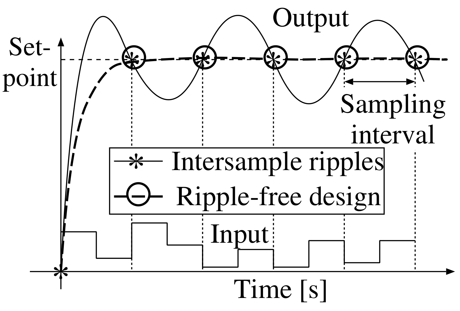
Dual-rate control, which is difficult to design because it is a time-varying system, is designed as a multi-variable time-invariant system by using lifting techniques [1,13,14]. Because of the high performance of recent digital computers, the update of a control input is often shorter than the sampling of a plant output. In such a dual-rate sampled-data control system, the control input, which is essentially a single signal, can be designed independently as a multi-input. Considering a single-input single-output (SISO) system as an example, the system can be viewed as a multi-input single-output system where the input signals are switched in time, as shown in Figure 1. In such a dual-rate system, as shown in Figure 2, because the time-switching control input is redundant with respect to the discrete-time output, the discrete-time output from that control input is not uniquely determined. As a result, because the control input may change between sampling instants, the intersample output might oscillate even if the plant output converges to the reference input at sampling instants [15,16,17,18,19]. The intersample ripple caused by the input oscillation is eliminated when the ripple-free condition is satisfied [20]. Ripple attenuation methods have been proposed in which this condition is not used [21,22,23]. However, a discrete-time model is needed to design feedforward and feedback controllers [21]; the frequency information for high-frequency disturbances is required to attenuate the intersample oscillation caused by disturbances [22] and a continuous-time dynamic model is needed to minimize the intersample control error [23]. The ripple-free condition is thus useful for solving the intersample ripple problem without the need for plant models or disturbance information. Because discrete-time sample performance is as important as intersample performance, the degradation of the sample performance of an existing system due to the elimination of intersample ripple must be prevented. For example, in the position control of the head in a hard disk drive, the head must follow the target position in the discrete-time domain to read and write user data [10,11]. To this end, a two-degree-of-freedom design in which intersample ripple is eliminated independently of the discrete-time performance is ideal [24].
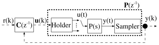
Figure 1.
Block diagram of a dual-rate sampled-data system.

Figure 2.
Trajectories with and without ripple.
A redundancy-based continuous-time-domain approach has been proposed [25]. In the method, a redundant variable is introduced based on the redundancy of a controlled plant model and used to reassign control inputs independently of the plant output. A discrete-time-domain method for redundant control design has also been proposed [26,27,28]. In continuous-time-domain design methods, the presence of redundancy depends on the controlled plant structure, whereas in discrete-time-domain design methods, because dual-rate systems are designed, redundancy is achieved even if the controlled plant is a non-redundant system.
Most ripple-free control methods adopt the model-based approach, whereas there is a data-driven (model-free) method [14,29]. In the conventional model-free method, only stable systems can be applied since open-loop control is executed for controller parameter tuning. Furthermore, a control system is newly designed, and hence the sample performance of an existing system is not maintained. In the conventional model-based dual-rate design method [26], a redundant variable is designed so that intersample ripple is eliminated in the steady state. Because the redundant variable is independent of the sampled plant output, intersample ripple is eliminated without changing the sampled output obtained by an existing control system, as shown in Figure 2. When the goal of the design is to eliminate the steady-state intersample ripple, it can be achieved by simply using steady-state characteristics (i.e., not all dynamic characteristics are required). Furthermore, because the steady-state characteristics of dual-rate systems can be identified by step responses, a model-free ripple-free design is also realizable. Therefore, in the present study, a model-free method for independently removing intersample ripple from the steady-state discrete-time output response is discussed. Specifically, the redundant variable is designed based on the null space of steady-state step responses. The step response is not a problem if the plant is stable, while if it is unstable, bounded values cannot be obtained. In the proposed method, since the add-on input is designed as long as bounded step responses are obtained in the steady state, both open-loop and closed-loop responses can be used. Therefore, for unstable plants, the proposed method is designed using stabilized closed-loop responses instead of open-loop responses. As a result, the proposed method is applicable to unstable plants as well as stable plants.
The rest of this paper is organized as follows: Section 2 describes a dual-rate sampled-data control system, and Section 3 describes the design method of an add-on input independent of the steady-state sampled plant output using step responses. The effectiveness of the proposed method is then shown in Section 4. Finally, conclusions are presented in Section 5. In the present study, denotes the backward shift operator, and and are an identity matrix and an zero matrix, respectively. and denote the spaces of positive integer and positive real numbers, respectively, and denotes the space of real numbers. Lightface denotes a scalar, and boldface denotes a vector or matrix.
2. Problem Statement
The controlled plant is assumed to be an SISO linear time-invariant continuous-time system. Because the plant is controlled by a digital computer in the discrete-time domain, the continuous-time plant output is sampled and converted to a discrete-time signal, and the discrete-time control input calculated by the digital computer is held and converted to a continuous-time signal. The holding and sampling intervals are assumed to be as follows.
Assumption A1.
- The holding interval T is known.
- The sampling interval is known.
where and . If the continuous-time plant output is sampled at intervals of T, the single-rate system is obtained:
where and are the sampled plant output and discrete-time control input, respectively, and is the transfer function in the discrete-time domain.
With Assumption A1, the controlled plant is modeled as a dual-rate system as follows [17,20]:
Assumption A2.
- has no zero at the origin.
- and are unknown.
A dual-rate control system is designed using the following control law:
where is the reference input for the plant output and is set to a step function. and are polynomial vectors and is a non-singular polynomial matrix.
Using the discrete-time control law, the closed-loop system from the reference input to the plant output is given as follows:
A block diagram of the designed dual-rate control system is shown in Figure 3.
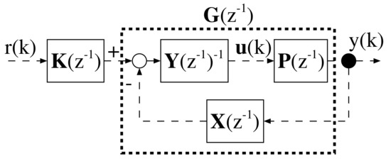
Figure 3.
Block diagram of dual-rate sampled-data control system.
Assumption A3.
For the closed-loop system, the following conditions are satisfied.
- The closed-loop system described by Equation (4) is stable.
- The steady-state discrete-time output converges to the reference input.
- The closed-loop transfer function is unknown.
Because the closed-loop system is stable from Assumption A3, the steady-state plant output is calculated as follows:
The closed-loop system from the reference input to the control input vector is given as follows:
When the control input is constant between sampling instants, there is no intersample ripple in the steady state [20]. The ripple-free condition is therefore described as follows:
If the control law is redesigned so as to satisfy the above condition, the existing correctly calibrated sampled response may degrade. In the next section, to prevent such degradation, the control law is extended using the null space and the ripple-free condition is then satisfied independently of the existing steady-state discrete-time response. As a result, intersample ripple is eliminated independently of the steady-state discrete-time response.
3. Ripple-Free Design Using Add-On Input
3.1. Extended Control Law Using Null Space of Step Responses
First, matrix is defined as follows.
Definition 1.
satisfies the following relational expressions:
where denotes the identified value of . The i-th element of can be identified by the steady-state value of the step response of Equation (6) when the elements of , excluding the i-th element, are set to 0. is unknown, whereas is available, and thus that satisfies Definition 1 is obtained.
Using , the control law is extended as follows:
where is an add-on input. The block diagram of the extended system is shown in Figure 4. The closed-loop system that uses the extended control law is given as follows:
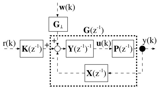
Figure 4.
Block diagram of extended system.
In the steady state, the output response is obtained as follows:
In the above equation, the second term on the right-hand side is always 0 for the bounded from Definition 1 when , and is independent of the steady-state sampled output obtained using Equation (3). Therefore, the steady-state sampled response, Equation (6), is maintained even when the extended control law is applied. Furthermore, using the add-on input, intersample ripple is eliminated without changing the steady-state sampled output response. In Section 3.2, is designed to satisfy the ripple-free condition in Equation (9).
3.2. Design of Add-On Input
The closed-loop system from both the reference and the add-on input to the control input vector is obtained as follows:
In the steady state, Equation (13) is described as follows:
Because the unknown is included in both and , these cannot be straightforwardly calculated. The present study proposes a lemma to obtain and without using .
Lemma 1.
Using , and are calculated as follows:
Proof.
From the matrix inversion lemma,
where is given by Equation () as follows:
, and are the design parameters of the control law, and is decided based on . Therefore, and are obtained even when the plant model is unknown.
Theorem 1.
The ripple-free condition is satisfied when is designed as follows:
where and are given as follows:
Proof.
From Equation (15), the steady-state control input between the sampling instants is given as follows:
For , the next equation must be satisfied:
From the above condition, all the conditions from to are summarized as follows:
As a result, the design condition (20) is obtained. □
Corollary 1.
If the controlled plant is stable, the identified steady-state plant gain is also obtained by step responses. Based on the null space of , the control law Equation (3) can be extended as follows:
where is a new add-on input, and a non-zero matrix is derived that satisfies the following equation:
Using the extended control law Equation (24), the corresponding closed-loop system is given as follows:
In the steady state, because the second term on the right-hand side of Equation (26) is 0, is independent of the steady-state output of Equation (4). is therefore designed in the same way as Theorem 1 so that intersample ripple is eliminated without changing the steady-state sampled output. However, the open-loop design method requires a plant model and is not applicable to unstable plants.
4. Simulation
To demonstrate the effectiveness of the proposed closed-loop-based method, two types of plant are controlled, namely stable and unstable plants. In the simulation, the reference input is given by set-point 1, and the holding and sampling intervals are set as 1 s and 2 s (), respectively.
4.1. Stable Plant
As a controlled plant, the following stable continuous-time system is given:
The dual-rate model is described as follows:
The coefficients of the control law Equation (3) are designed as follows:
where the poles of the designed closed-loop characteristic polynomial are , and , and the steady-state gain from the reference input to the plant output is 1.
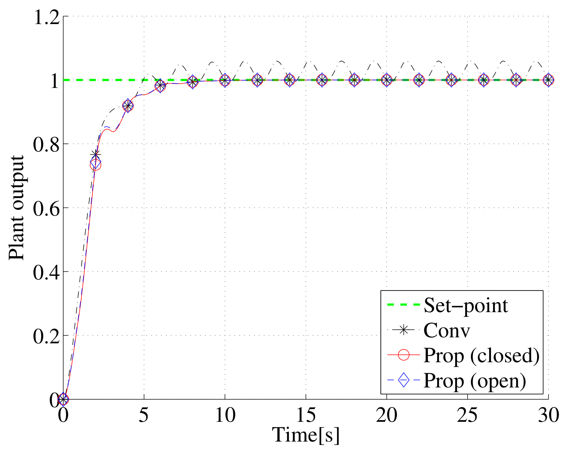
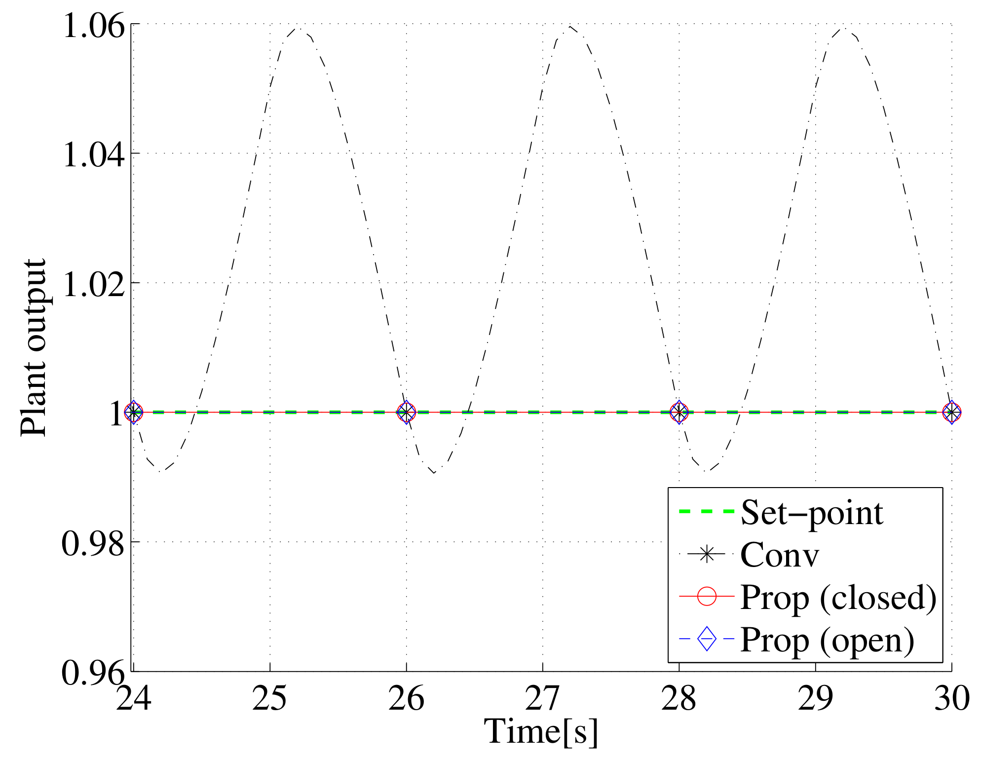
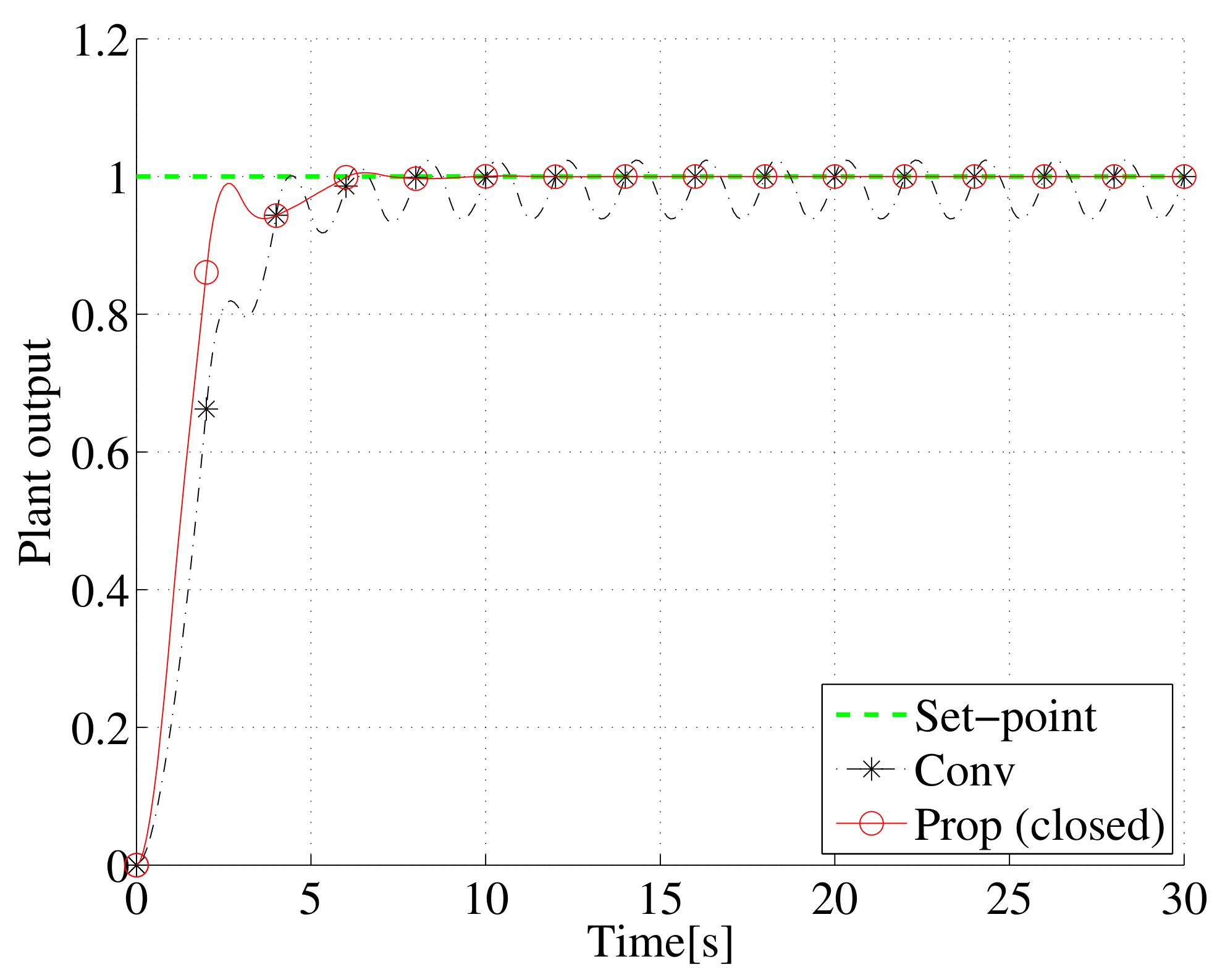
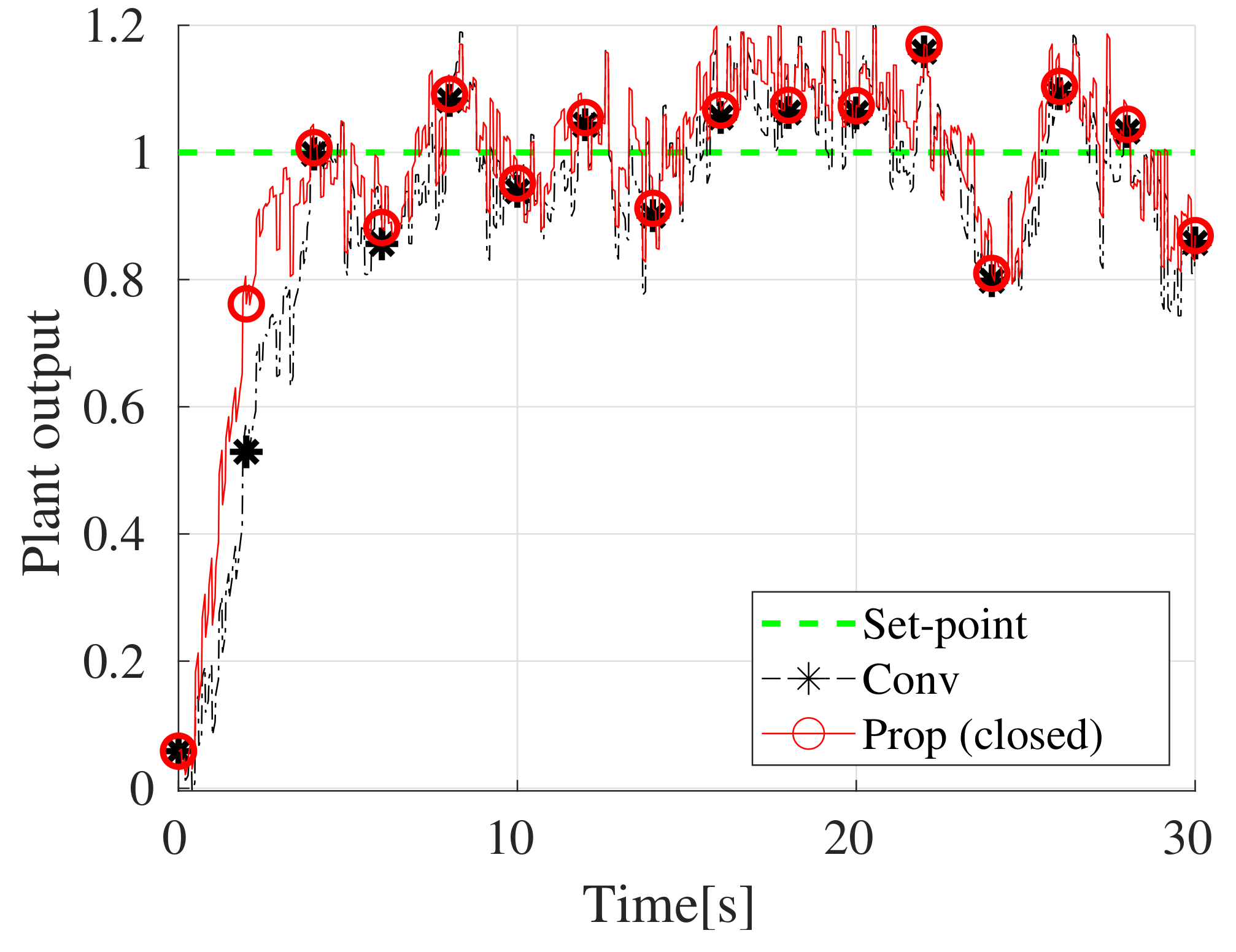
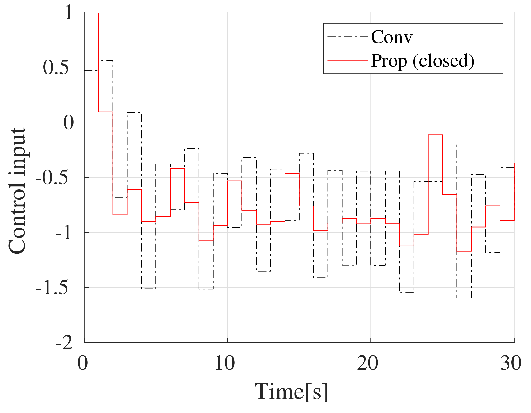
First, the control result obtained using the control law in Equation (3) with the coefficients designed as described above is shown in Figure 5, Figure 6 and Figure 7, where the output and input trajectories are plotted by the black dashed-dotted lines, and the sampled output trajectory is plotted by black ‘*’ symbols. It can be seen that the intersample output oscillates even though the sampled output converges to the reference input. This is because the steady-state gain is , and the control input is thus not constant, even though the control error between the reference input and the sampled plant output is 0.
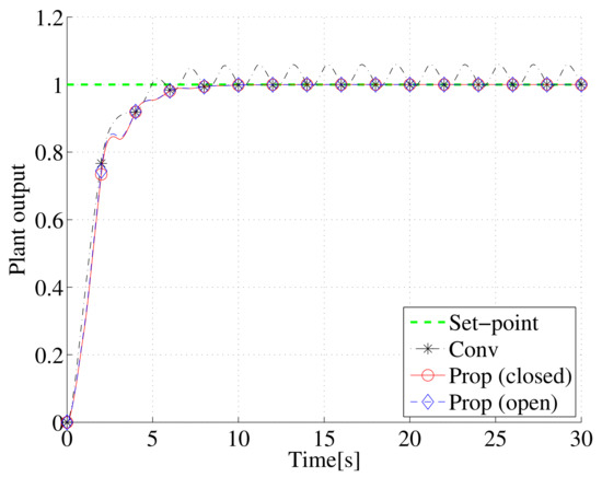
Figure 5.
Output trajectories of stable plant.
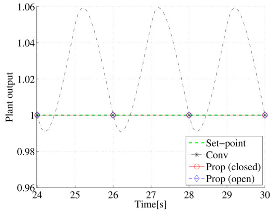
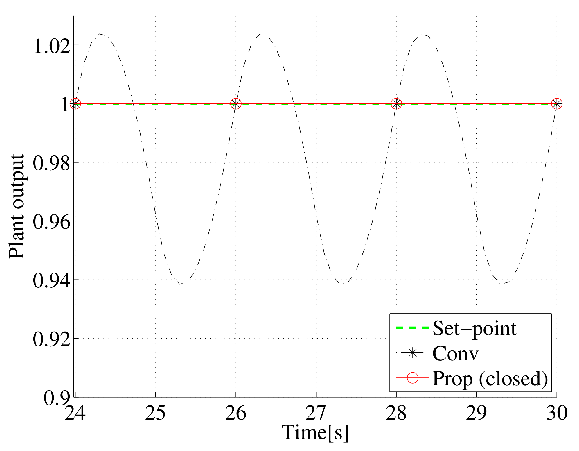
Figure 6.
Steady-state trajectories for data in Figure 5.
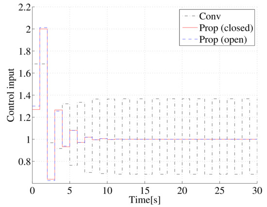
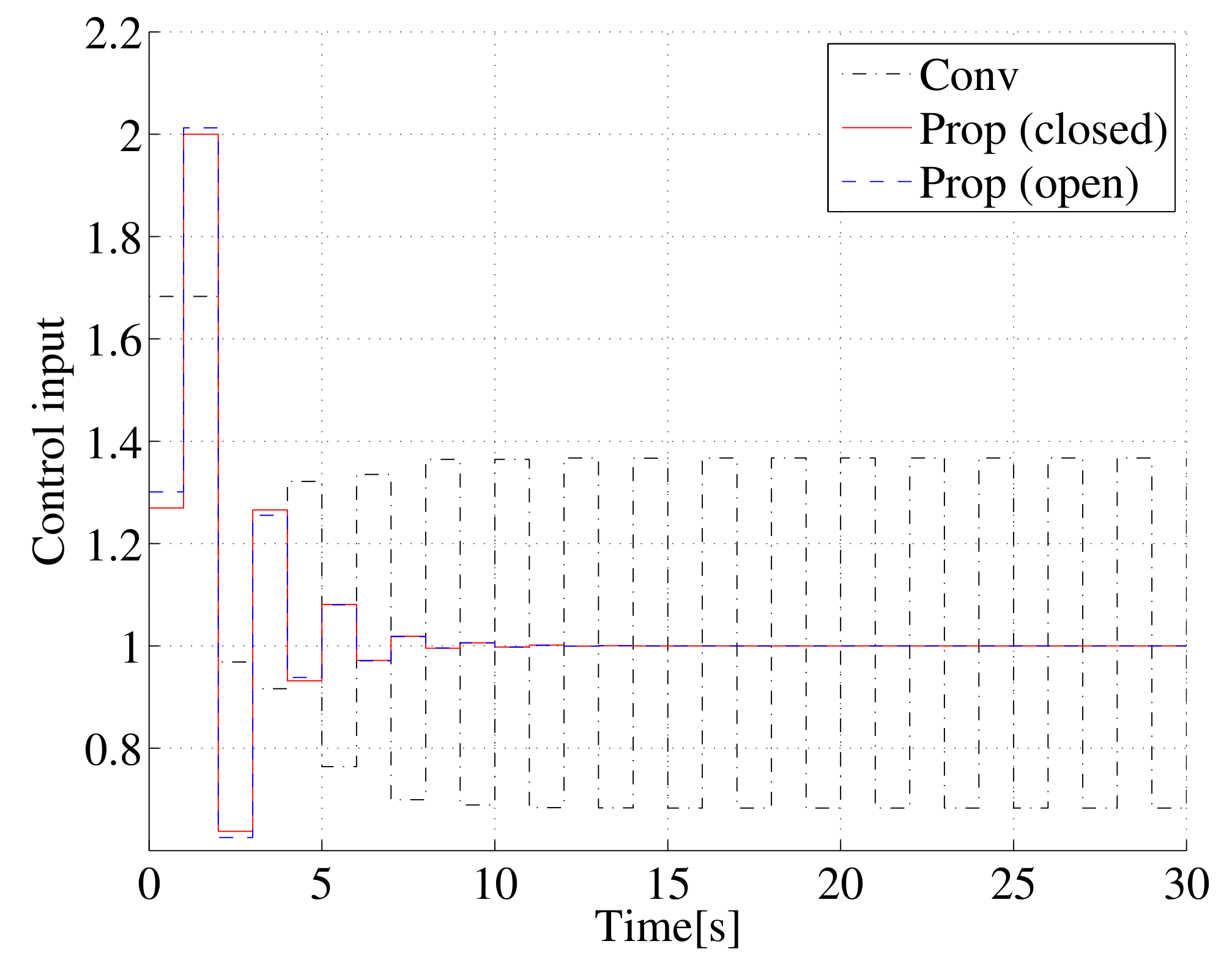
Figure 7.
Input trajectories for stable plant.
Second, the simulation result for the proposed method is presented. From two close-loop step responses of 50 s, where is set to and , respectively, the steady-state gain of the closed-loop system is identified as follows:
The vector orthogonal to the steady-state gain is decided as follows:
Using Equation (20), the add-on input is designed as follows:
Equation (29) shows that is designed as a constant. The control result obtained using the proposed closed-loop-based extension method is also shown in Figure 5, Figure 6 and Figure 7, where the output and input trajectories are plotted by the red solid lines, and the sampled output trajectory is plotted by red ‘∘’ symbols. It can be seen that the intersample output as well as the sampled output converge to the reference input without intersample ripple. Furthermore, the sampled output response obtained by the conventional non-extension method is maintained in the steady state even though the trajectories of the control inputs obtained by the proposed and conventional methods are quite different.
Third, for comparison with the proposed closed-loop-based extension method, the control result obtained using the open-loop-based extension method is presented. In the open-loop extension method, the steady-state gain of a controlled plant is required. Hence, is identified from two step responses of 50 s, where is set to and , respectively:
From the obtained steady-state gain, the add-on input is designed as follows:
The control result of the open-loop extension method is also shown in Figure 5, Figure 6 and Figure 7, where the output and input trajectories are plotted by the blue dashed lines, and the sampled output trajectory is plotted by blue ‘♢’ symbols. It can be seen that when the steady-state gain of the controlled plant is available, the intersample ripple is eliminated and the steady-state sampled response obtained by the conventional non-extension method is maintained.
4.2. Unstable Plant
As an unstable plant, the following transfer function is considered:
The corresponding transfer functions in a dual-rate system are given as follows:
The coefficients of the control law Equation (3) are designed as follows:
where , and the poles of the closed-loop characteristic polynomial are , and .
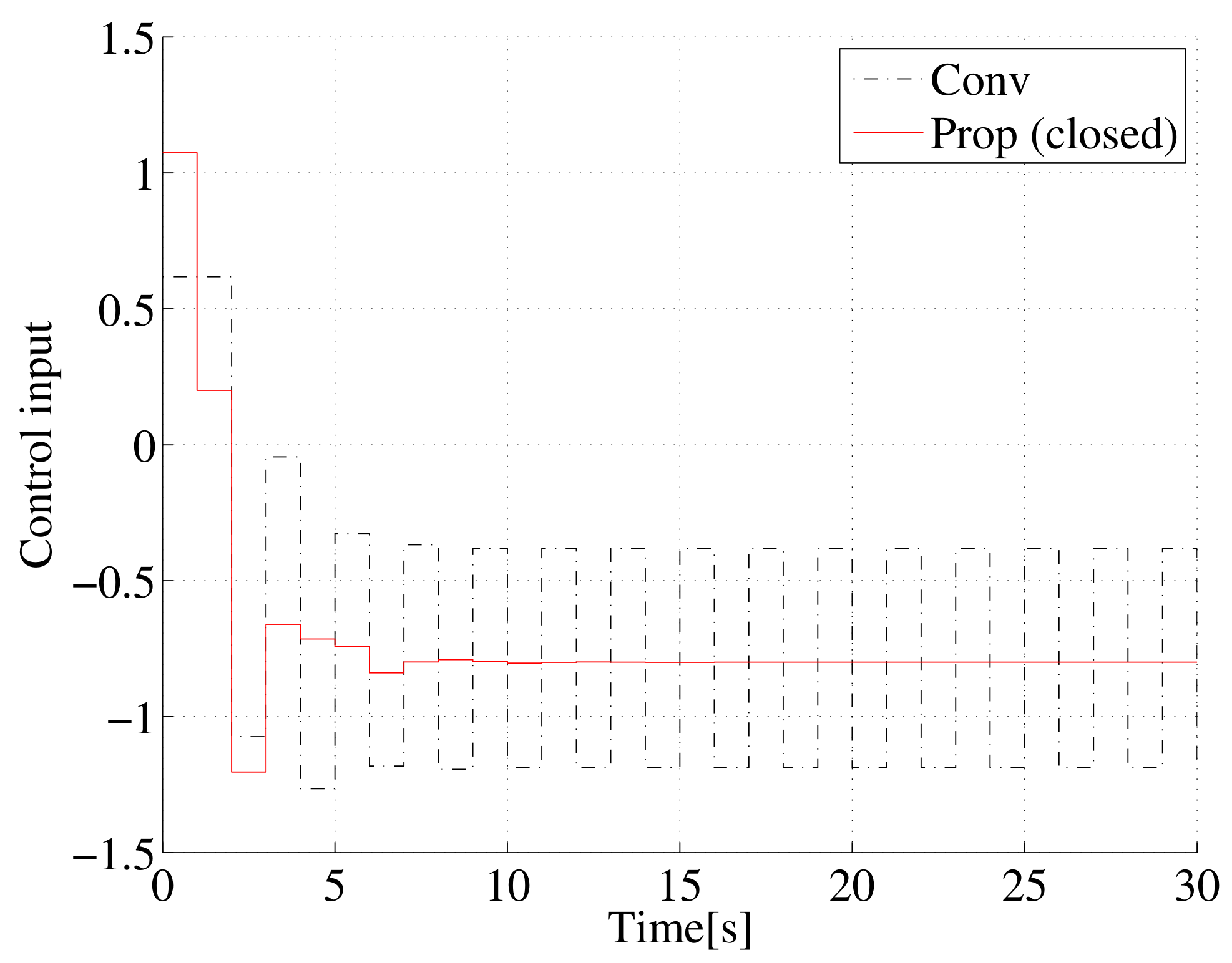
The control result obtained by the non-extension control law with the coefficients designed as described above is shown in Figure 8, Figure 9 and Figure 10, where the output and input trajectories are plotted by the black dashed-dotted lines, and the sampled output trajectory is plotted by black ‘*’ symbols. As in the case of the stable plant, the intersample output oscillates even though the sampled output follows the reference input. The reason for this intersample oscillation is the oscillation of the control input, and .
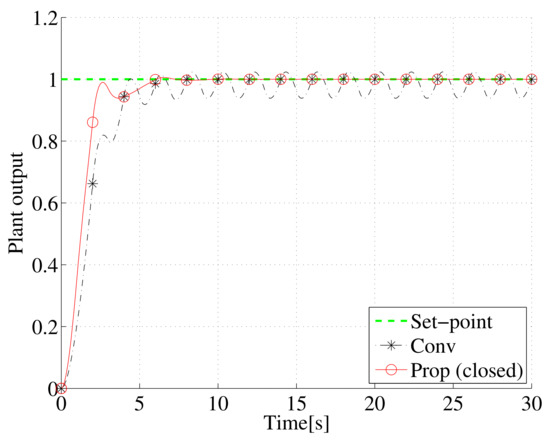
Figure 8.
Output trajectories of unstable plant.
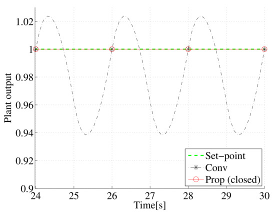
Figure 9.
Steady-state trajectories for data in Figure 8.

Figure 10.
Input trajectories for unstable plant.
The open-loop-based method is not applicable to the unstable plant, whereas the proposed method is, because of the closed-loop-based design.
From two step responses of 30 s, the identified steady-state gain of the closed-loop system is given as follows:
The corresponding orthogonal vector is given as follows:
From Equation (20), the add-on input is obtained as follows:
The control result obtained using the proposed method is shown in Figure 8, Figure 9 and Figure 10, where the output and input trajectories are plotted by the red solid lines, and the sampled output trajectory is plotted by red ‘∘’ symbols. As shown in Figure 8 and Figure 9, the steady-state sampled output responses obtained by the conventional non-extension and proposed methods are the same. Furthermore, intersample ripple is eliminated using the proposed method.
The present study assumes that there will be no noise or disturbance, but in reality, there may be impacts. An example is shown where the output is disturbed by noise of variance . Since the step response is affected by noise, the correct steady-state gain cannot be obtained:
Therefore, the wrong orthogonal vector is given as follows:
Simulation results in the presence of noise are shown in Figure 11 and Figure 12, where the same noise is applied by fixing the seed value. Even when the proposed method is applied, the control input oscillates and intersample ripple is not eliminated.

Figure 11.
Output trajectories of unstable plant in the presence of noise.
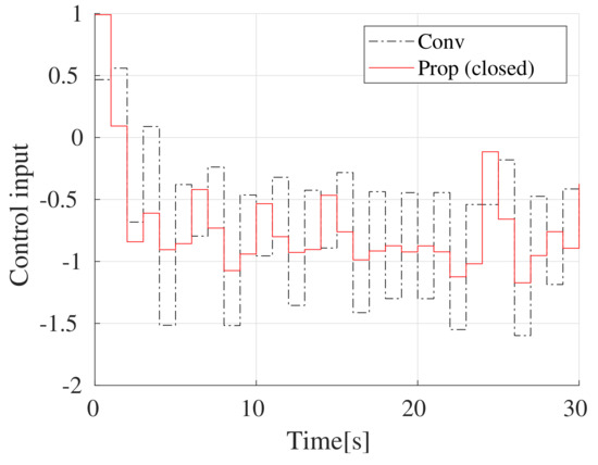
Figure 12.
Input trajectories for unstable plant in the presence of noise.
5. Conclusions
The present study proposed a design method for a dual-rate sampled-data control system, in which the sampling interval is longer than the holding interval. In such a system, even when the sampled output converges to the reference input, the intersample output might oscillate because the control input may change between sampling instants. In the proposed method, an existing control law is extended by introducing an add-on input based on the null space of step responses to eliminate intersample ripple independently of an existing steady-state sampled response. The proposed method is based on step responses and is easily implemented. Since the present study proposes the closed-loop-based method as well as the open-loop-based method, the proposed method can be applied to an unstable plant.
In the present study, the controlled plant is limited to linear time-invariant systems; however, the proposed method can be applied to wider classes. The proposed method is applicable when the steady-state output is uniquely determined for the steady-state input, but difficult otherwise. Therefore, our future work is to clarify the class of controlled plants in which the proposed add-on design method is applicable. The present study assumes the case where there is no unknown information such as noise. Therefore, it is necessary to deal with cases where the steady-state gains cannot be estimated correctly due to disturbances and so on. In addition, verification using actual equipment is also an issue for the future. Furthermore, in the present study, the add-on input is designed so that the intersample response is improved in the steady state. Therefore, one of the future works is to design the add-on input to improve the transient response as well as the steady-state response.
Author Contributions
Conceptualization, T.S. and R.Y.; methodology, T.S., R.Y. and N.K.; software, T.S. and R.Y.; validation, N.K.; formal analysis, T.S., R.Y. and N.K.; investigation, T.S. and N.K.; resources, T.S. and N.K.; data curation, T.S., R.Y. and N.K.; writing—original draft preparation, T.S. and R.Y.; writing—review and editing, T.S. and N.K.; visualization, T.S., R.Y. and N.K.; supervision, T.S.; project administration, T.S.; funding acquisition, T.S. and N.K. All authors have read and agreed to the published version of the manuscript.
Funding
This research received no external funding.
Institutional Review Board Statement
Not applicable.
Informed Consent Statement
Not applicable.
Acknowledgments
The present study was supported by the Suzuki Foundation.
Conflicts of Interest
The authors declare no conflict of interest.
References
- Chen, T.; Francis, B. Optimal Sampled-Data Control Systems; Springer: London, UK, 1995. [Google Scholar]
- Åström, K.J.; Wittenmark, B. Computer-Controlled Systems: Theory & Design, 3rd ed.; Prentice Hall: Upper Saddle River, NJ, USA, 1997. [Google Scholar]
- Araki, M.; Hagiwara, T. Pole assignment by multirate sampled-data output feedback. Int. J. Control 1986, 44, 1661–1673. [Google Scholar]
- Araki, M.; Yamamoto, K. Multivariable Multirate Sampled-data Systems: State-space Description, Transfer Characteristics, and Nyquist Criterion. IEEE Trans. Autom. Control 1986, 31, 145–154. [Google Scholar]
- Salt, J.; Albertos, P. Model-Based Multirate Controllers Design. IEEE Trans. Control Syst. Technol. 2005, 13, 988–997. [Google Scholar]
- Jia, Y.; Chai, T. A data-driven dual-rate control method for a heat exchanging process. IEEE Trans. Ind. Electron. 2016, 64, 4158–4168. [Google Scholar]
- Carini, P.; Micheli, R.; Scattolini, R. Multirate self-tuning predictive control with applications to binary distillation column. Int. J. Syst. Sci. 1990, 21, 51–64. [Google Scholar]
- Zhang, B.; Zhou, K.; Wang, D. Multirate Repetitive Control for PWM DC/AC Converters. IEEE Trans. Ind. Electron. 2014, 61, 2883–2890. [Google Scholar]
- Furusaka, T.; Sato, T.; Kawaguchi, N.; Araki, N.; Konishi, Y. Consensus Control of Dual-rate Multi-agent Systems with Quantized Communication. IEEE Access 2020, 8, 97557–97563. [Google Scholar]
- Chen, B.M.; Lee, T.H.; Venkataramanan, V. Hard Disk Drive Servo Systems; Springer: Berlin/Heidelberg, Germany, 2002. [Google Scholar]
- Mamun, A.A.; Guo, X.; Bi, B. Hard Disk Drive; Automation and Control Engineering; CRC Press: Boca Raton, FL, USA, 2007. [Google Scholar]
- Salt, J.; Tomizuka, M. Hard disk drive control by model based dual-rate controller. Computation saving by interlacing. Mechatronics 2014, 24, 691–700. [Google Scholar]
- Li, D.; Shah, S.; Chen, T. Analysis of Dual-Rate Inferential Control Systems. Automatica 2002, 38, 1053–1059. [Google Scholar]
- Sato, T.; Kusakabe, T.; Himi, K.; Araki, N.; Konish, Y. Ripple-free Data-driven Dual-rate Controller Using Lifting Technique: Application to a Physical Rotation System. IEEE Trans. Control Syst. Technol. 2021, 29, 1332–1339. [Google Scholar]
- Moore, K.; Bhattacharyya, S.; Dahleh, M. Capabilitied and Limitations of Multirate Control Schemes. Automatica 1993, 29, 941–951. [Google Scholar]
- Sheng, J.; Chen, T.; Shah, S.L. Multirate Generalized Predictive Control for Sampled-Data Systems. Dyn. Contin. Discret. Impuls. Syst. Ser. Appl. Algorithms 2001, 8, 485–499. [Google Scholar]
- Ishitobi, M.; Kawanaka, M.; Nishi, H. Ripple-Suppressed Multirate Adaptive Control. In Proceedings of the 15th IFAC World Congress, Barcelona, Spain, 21–26 July 2002; pp. 327–332. [Google Scholar]
- Salt, J.; Sandoval, J.; Albertos, P. Dual-Rate Control Ripple Detection by an Approximate Frequency Respoinse Methodology. In Proceedings of the Fourth IEEE Congress of Electronics, Robotics, and Automotive Mechanics, Cuernavaca, Mexico, 25–28 September 2007; pp. 89–94. [Google Scholar]
- Oomen, T.; van de Wijdeven, J.; Bosgra, O. Suppressing intersample behavior in iterative learning control. Automatica 2009, 45, 981–988. [Google Scholar]
- Tangirala, A.; Li, D.; Patwardhan, R.; Shah, S.; Chen, T. Ripple-Free Conditions for lifted Multirate Control Systems. Automatica 2001, 37, 1637–1645. [Google Scholar]
- Jia, Q.; Oooi, K.; Wu, D. Multirate Control of an HDD Servo System with Intersample Ripple Free. IEEE Tran. Megnetics 2002, 38, 2192–2194. [Google Scholar]
- Atsumi, T.; Messner, W.C. Mixed Sensitivity Problem in Sampled-Data Positioning Control Systems. J. Syst. Des. Dyn. 2011, 5, 1294–1309. [Google Scholar]
- Inoue, A.; Sato, T.; Deng, M.; Yanou, A. A Multi-rate Optimal Controller to Suppress Ripples at Transient State. In Proceedings of the 2018 IEEE International Conference on Systems, Man, and Cybernetics, Miyazaki, Japan, 7–10 October 2018; pp. 2641–2646. [Google Scholar]
- Sato, T. Parametric Design of a Dual-rate Controller for Improvement in Steady-state Intersample Response. SICE J. Control Meas. Syst. Integr. 2008, 1, 329–334. [Google Scholar]
- Zaccarian, L. Dynamic Allocation for Input Redundant Control Systems. Automatica 2009, 45, 1431–1438. [Google Scholar]
- Sato, T.; Kawaguchi, N.; Araki, N.; Konishi, Y. Ripple-free Design for an SISO Dual-rate Control System. In Proceedings of the 22th IEEE International Conference on Emerging Technologies and Factory Automation, Limassol, Cyprus, 12–15 September 2017. [Google Scholar]
- Yasui, R.; Kawaguchi, N.; Sato, T.; Araki, N.; Konishi, Y. Dual-rate Control System Extension Using the Null-space of Closed-loop System. IEEJ Trans. Electr. Electron. Eng. 2020, 15, 135–139. [Google Scholar]
- Yasui, R.; Kawaguchi, N.; Sato, T.; Araki, N.; Konishi, Y. Steady-state Dual-rate Open-loop Transfer Function Model-based Ripple-free Design. IEEJ Trans. Electr. Electron. Eng. 2021, 16, 1435–1437. [Google Scholar]
- Sato, T.; Sakai, Y.; Kawaguchi, N.; Arrieta, O. Dual-Rate Data-Driven Virtual Reference Feedback Tuning: Improvement in Fast-Tracking Performance and Ripple-Free Design. IEEE Access 2021, 9, 144426–144437. [Google Scholar]


Publisher’s Note: MDPI stays neutral with regard to jurisdictional claims in published maps and institutional affiliations. |
© 2022 by the authors. Licensee MDPI, Basel, Switzerland. This article is an open access article distributed under the terms and conditions of the Creative Commons Attribution (CC BY) license (https://creativecommons.org/licenses/by/4.0/).