
Analysis of a Three-Phase Induction Motor with a Double–Triple-Layer Stator Winding Configuration Operating with Broken Rotor Bar Faults


Abstract
:1. Introduction
2. Related Work
3. Materials and Methodology
3.1. Specifications and Ratings
3.2. Double–Triple-Layer Stator Winding Configuration
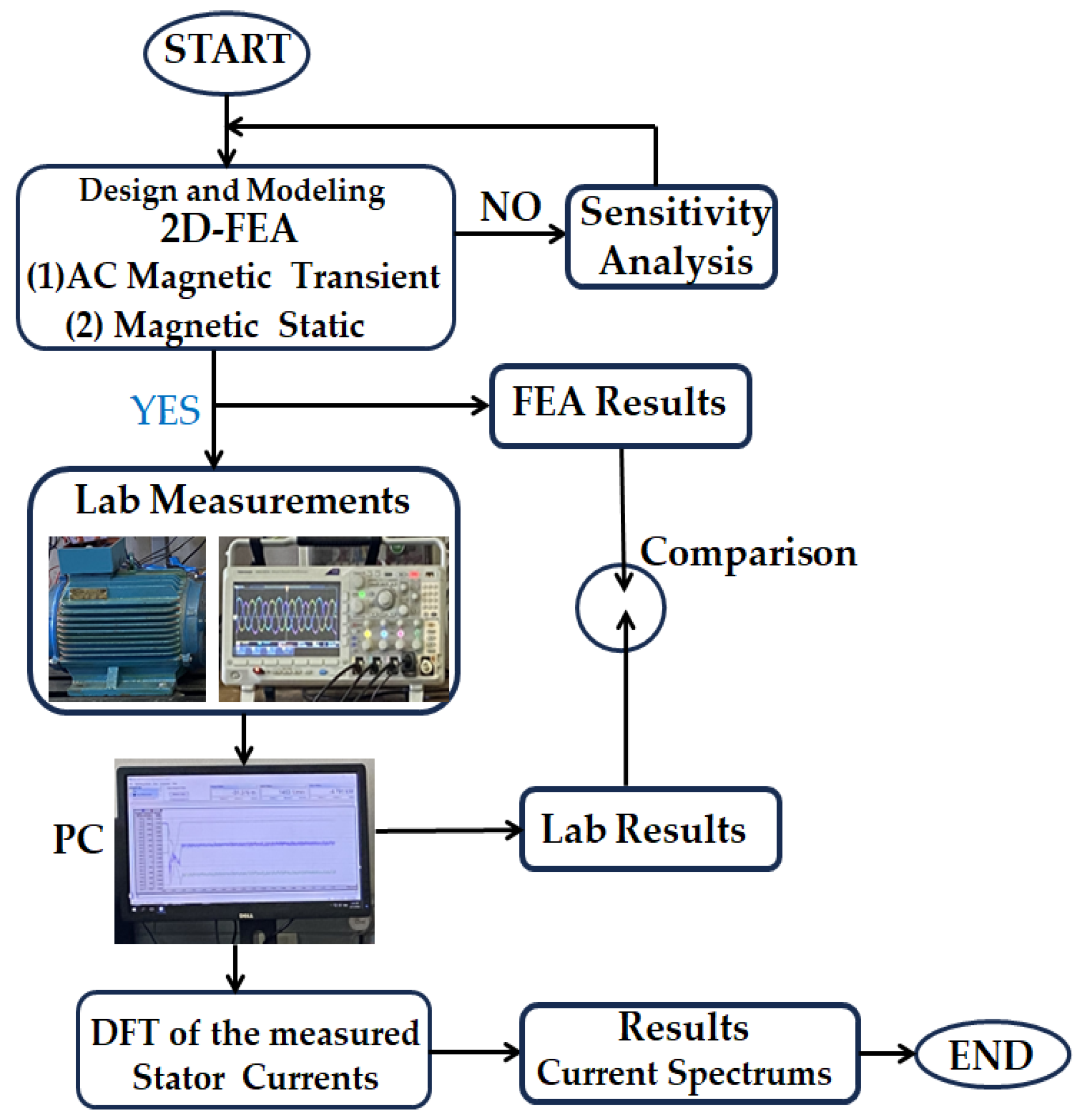
3.3. Approach
4. Results and Discussions
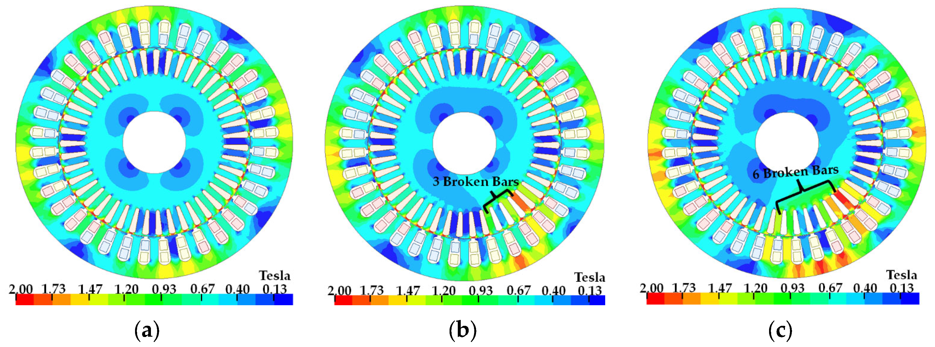
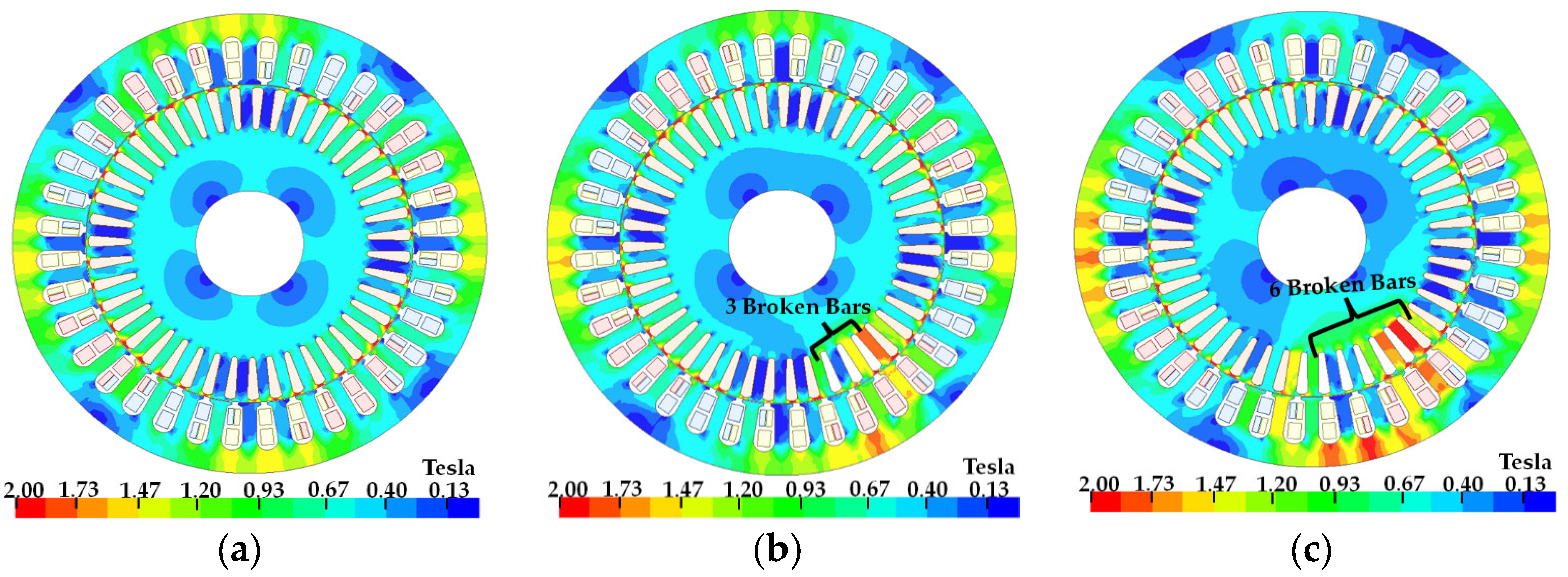
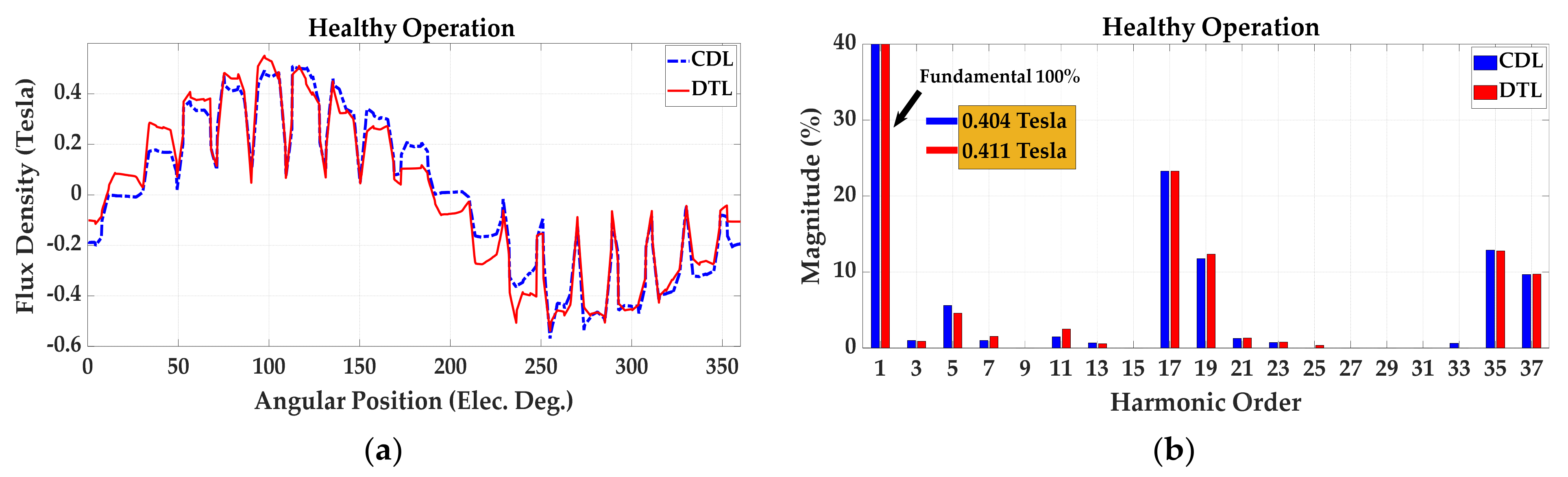
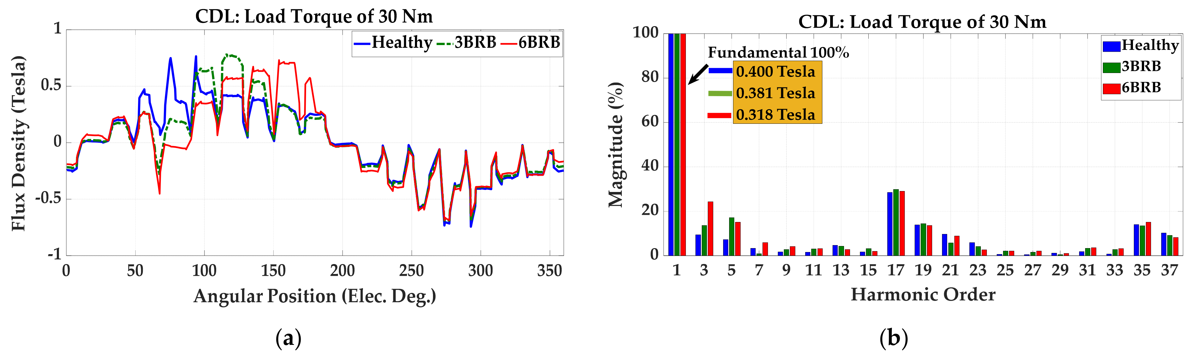
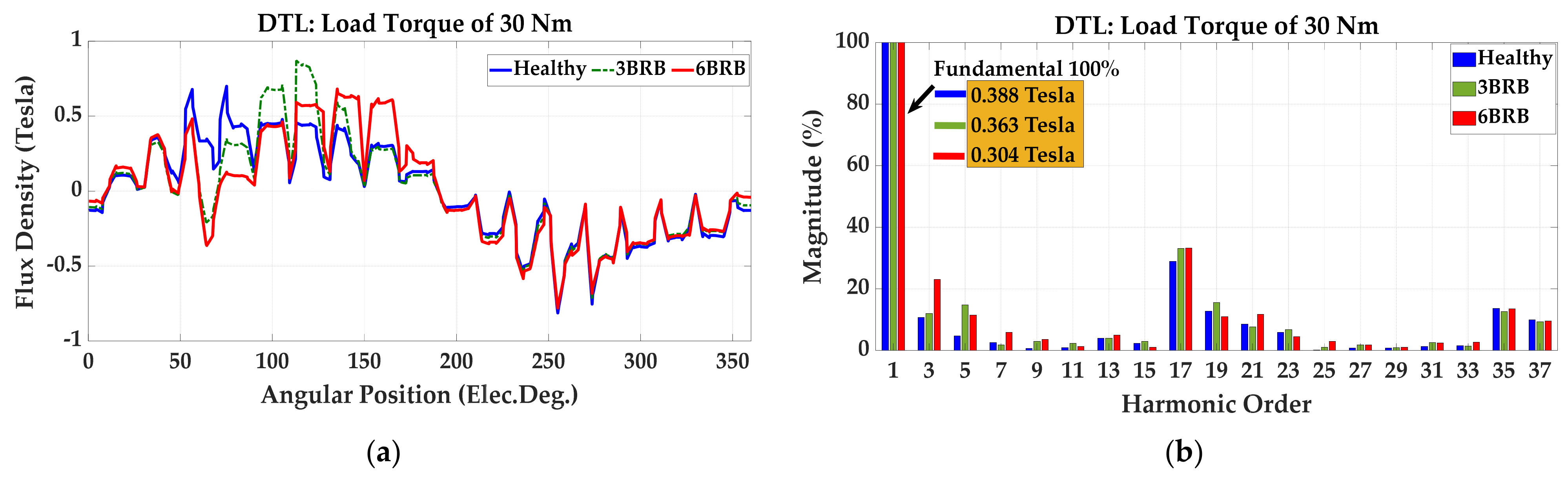
4.1. Effect of Broken Rotor Bars on Flux Density
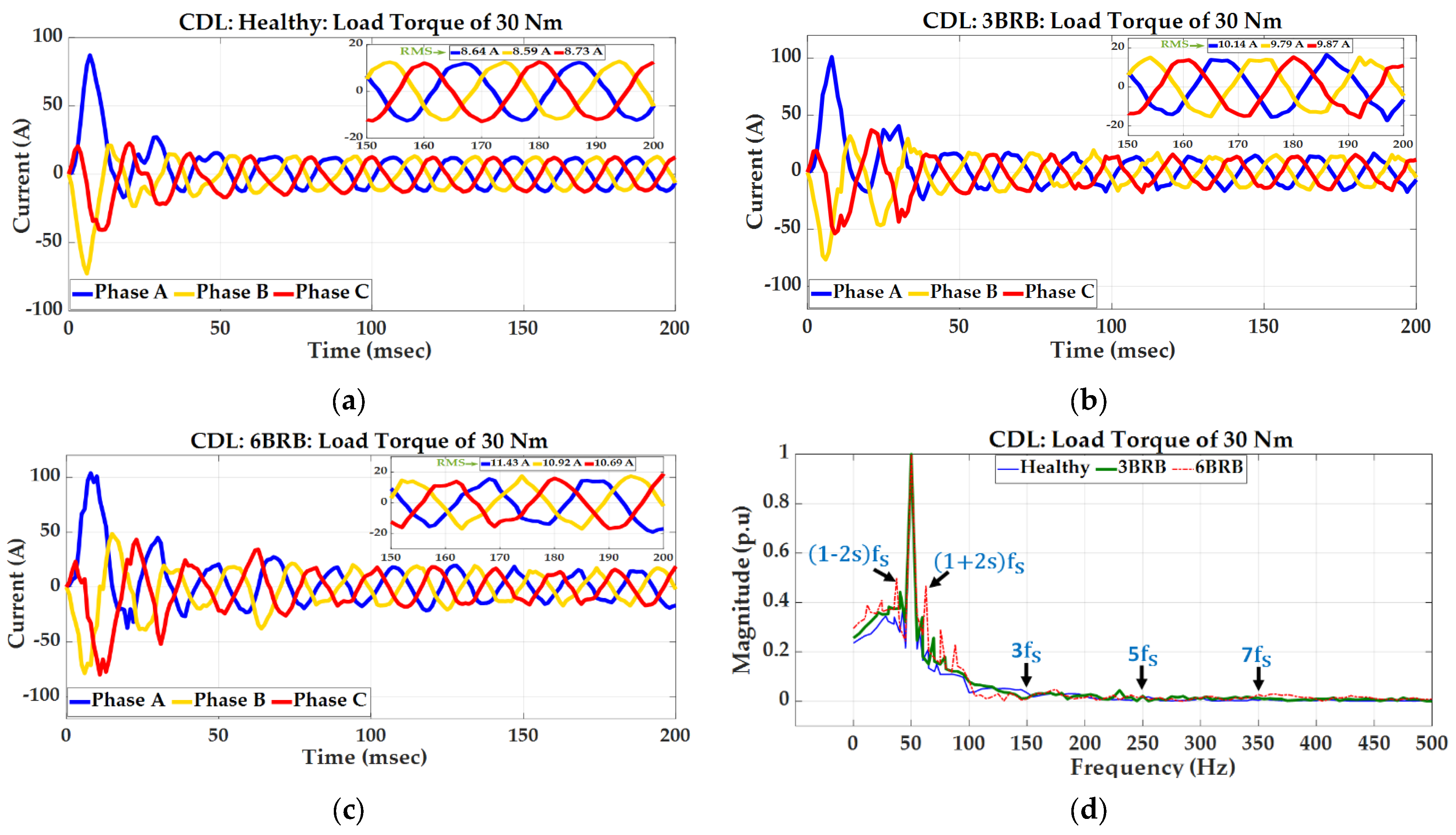
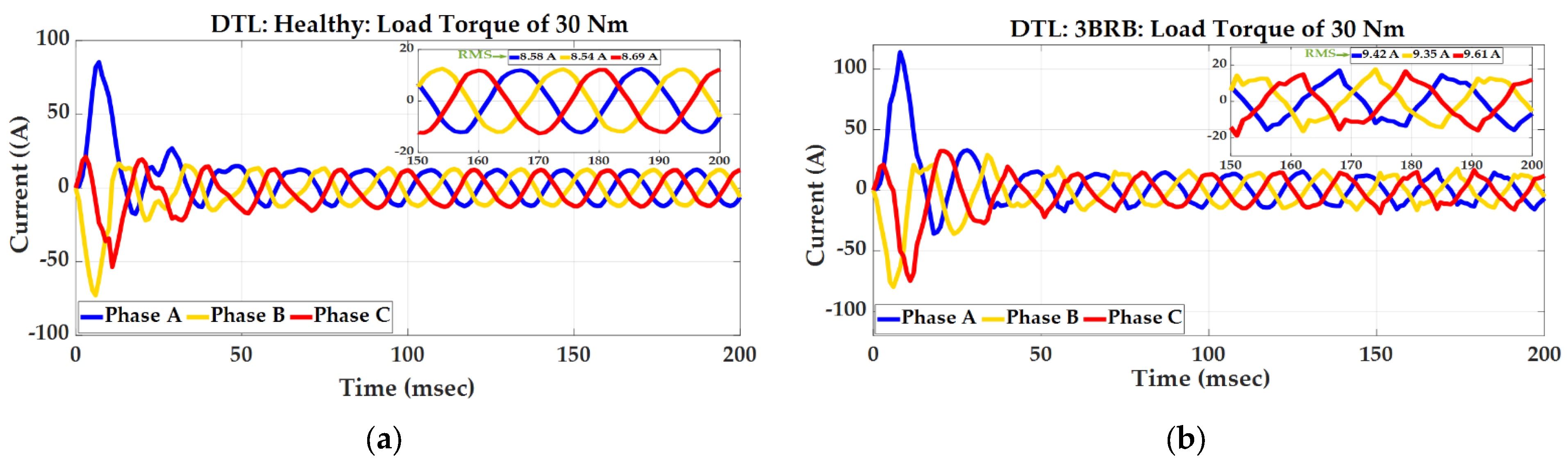
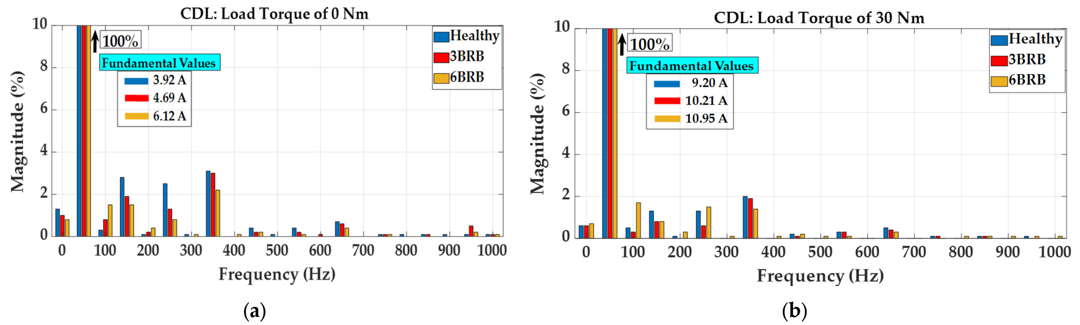
4.2. Effect of Broken Rotor Bars on the Current Signature of the Loaded SCIM
4.3. Machines’ Parameters
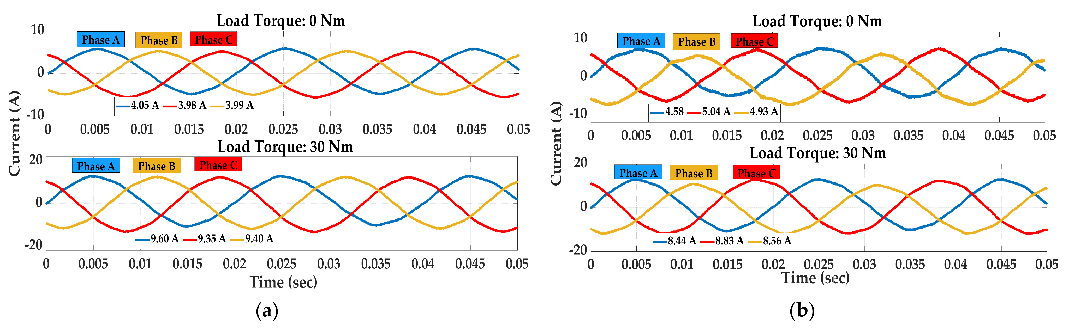
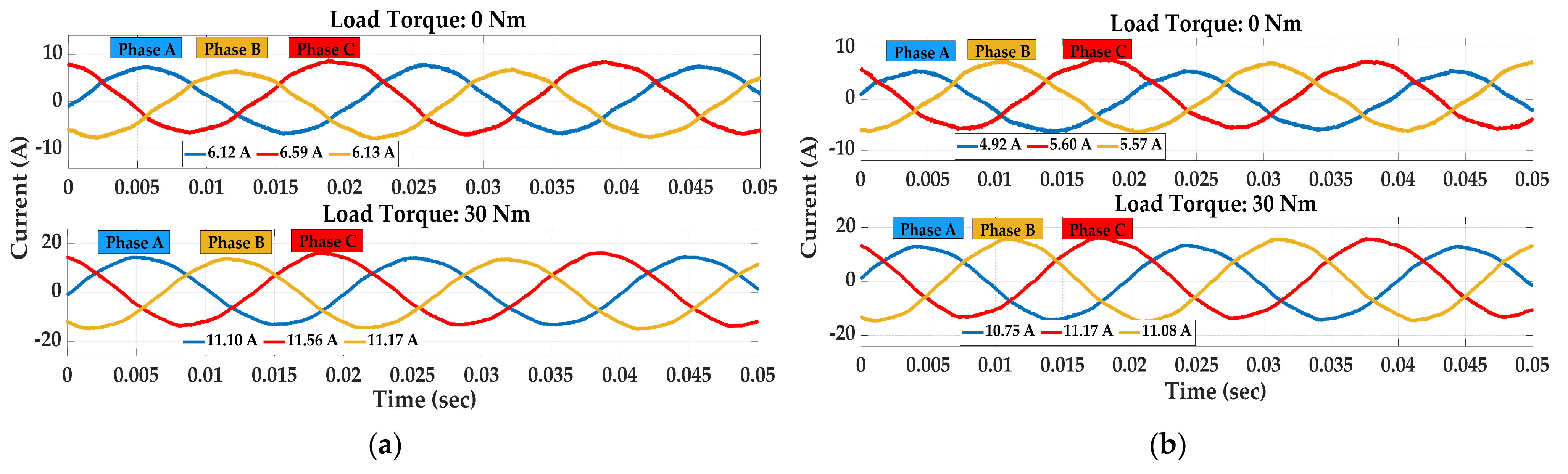
4.4. Analysis of Measured Stator Currents
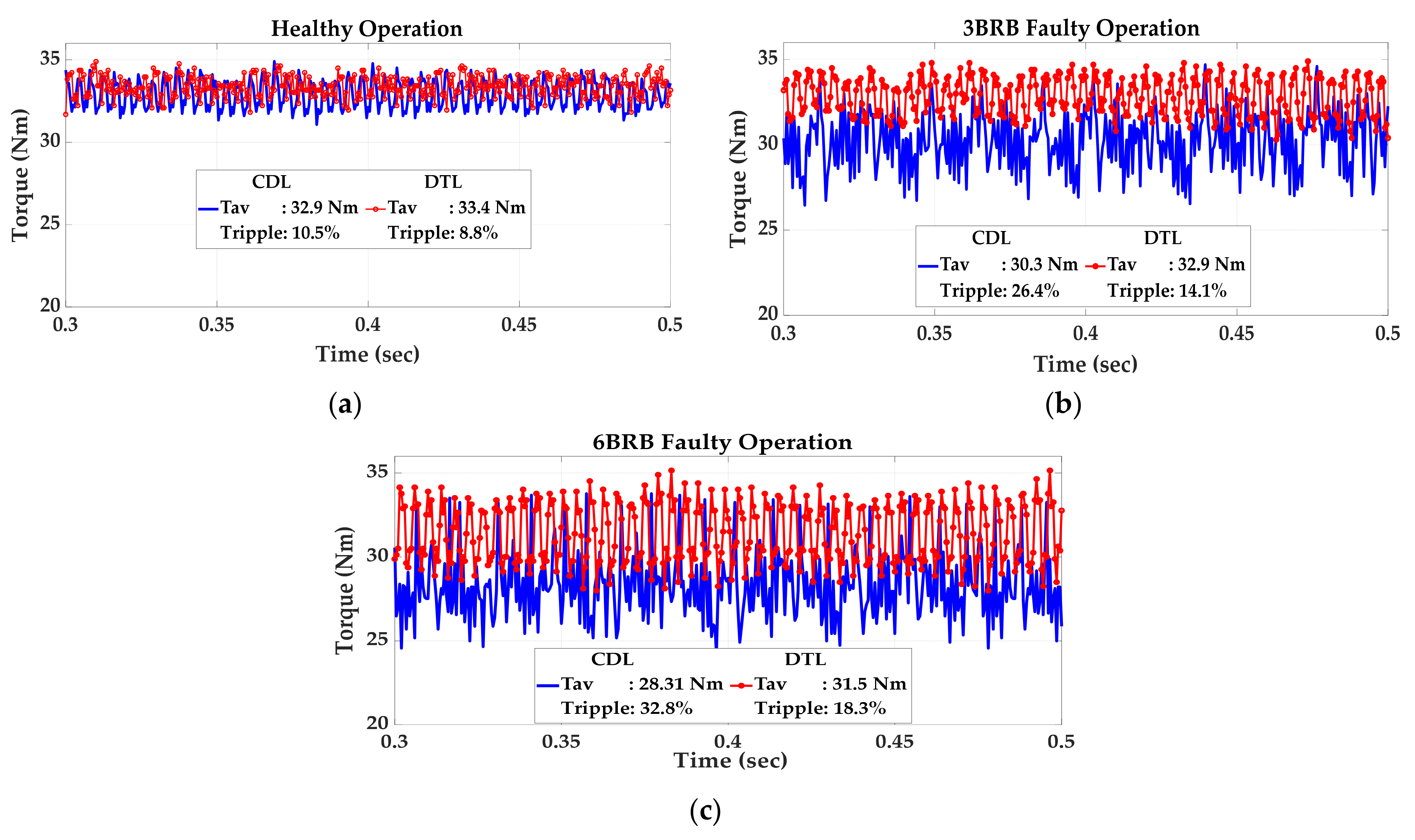
4.5. Analysis of Key Performance Parameters
5. Conclusions
Funding
Data Availability Statement
Conflicts of Interest
References
- Salon, S.; Burow, D.; DeBortoli, M.; Slavik, C. Effects of slot closure and magnetic saturation on induction machine behavior. IEEE Trans. Magn. 1994, 30, 3697–3700. [Google Scholar] [CrossRef]
- Makhetha, E.; Muteba, M.; Nicolae, D.V. Effect of Rotor bar Shape and Stator Slot Opening on the Performance of Three Phase Squirrel Cage Induction Motors with Broken Rotor Bars. In Proceedings of the Southern African Universities Power Engineering Conference/Robotics and Mechatronics/Pattern Recognition Association of South Africa, Bloemfontein, South Africa, 28–30 January 2019; pp. 463–468. [Google Scholar]
- Thomson, W.T.; Fenger, M. Current signature analysis to detect induction motor faults. IEEE Ind. Appl. Mag. 2001, 7, 26–34. [Google Scholar] [CrossRef]
- Zhang, P.; Du, Y.; Habetler, T.G.; Lu, B. A Survey of Condition Monitoring and Protection Methods for Medium-Voltage Induction Motors. IEEE Trans. Ind. Appl. 2011, 47, 34–46. [Google Scholar] [CrossRef]
- Zouzou, S.E.; Khelif, S.; Halem, N.; Sahraoui, M. Analysis of induction motor with broken rotor bars using finite element method. In Proceedings of the 2nd International Conference on Electric Power and Energy Conversion Systems, Sharjah, United Arab Emirates, 15–17 November 2011; pp. 1–5. [Google Scholar]
- Douglas, H.; Pillay, P.; Ziarani, A.K. Broken rotor bar detection in induction machines with transient operating speeds. IEEE Trans. Ener. Conv. 2005, 20, 135–141. [Google Scholar] [CrossRef]
- Müller, G.H.; Landy, C.F. Detection of broken rotor bars part I—New theory. Trans. SAIEE 2003, 94, 7–18. [Google Scholar]
- Müller, G.H.; Landy, C.F. Detection of broken rotor bars part II—Experimental verification. Trans. SAIEE 2003, 94, 19–28. [Google Scholar]
- Atta, M.E.E.-D.; Ibrahim, D.K.; Gilany, M.I. Broken Bar Fault Detection and Diagnosis Techniques for Induction Motors and Drives: State of the Art. IEEE Access 2022, 10, 88504–88526. [Google Scholar] [CrossRef]
- Resendiz-Ochoa, E.; Osornio-Rios, R.A.; Benitez-Rangel, J.P.; Romero-Troncoso, R.D.J.; Morales-Hernandez, L.A. Induction Motor Failure Analysis: An Automatic Methodology Based on Infrared Imaging. IEEE Access 2018, 6, 76993–77003. [Google Scholar] [CrossRef]
- Martin-Diaz, I.; Morinigo-Sotelo, D.; Duque-Perez, O.; Romero-Troncoso, D.J. Advances in Classifier Evaluation: Novel Insights for an Electric Data-Driven Motor Diagnosis. IEEE Access 2016, 4, 7028–7038. [Google Scholar] [CrossRef]
- Amezquita-Sanchez, J.; Valtierra-Rodriguez, M.; Pérez-Ramírez, C.; Camarena-Martinez, D.; Garcia-Perez, A.; Romero-Troncoso, R. Fractal dimension and fuzzy logic systems for broken rotor bar detection in induction motors at start-up and steady-state regimes. Meas. Sci. Technol. 2017, 28, 075001. [Google Scholar] [CrossRef]
- Morinigo-Sotelo, D.; Romero-Troncoso, R.d.J.; Panagiotou, P.A.; Antonino-Daviu, J.A.; Gyftakis, K.N. Reliable detection of rotor bars breakage in induction motors via music and ZSC. IEEE Trans. Ind. Appl. 2018, 54, 1224–1234. [Google Scholar] [CrossRef]
- Uddin, M.N.; Wang, W.; Huang, Z.R. Modeling and Minimization of Speed Ripple of a Faulty Induction Motor with Broken Rotor Bars. In Proceedings of the IEEE Industry Applications Society Annual Meeting, Edmonton, AB, Canada, 5–9 October 2008; pp. 1–8. [Google Scholar]
- Bonivento, C.; Isidori, A.; Marconi, L.; Paoli, A. Implicit fault-tolerant control: Application to induction motors. Automatica 2004, 40, 355–371. [Google Scholar] [CrossRef]
- Boldea, I.; Tutelea, L. Electric Machines: Steady State, Transients, and Design with Matlab; CRC Press: Boca Raton, FL, USA; Taylor & Francis: Abingdon, UK, 2010. [Google Scholar]
- Muteba, M.; Nicolae, V.D. Influence of Mixed Winding Arrangements on Torque Ripples of Five-Phase Induction Machines. Electr. Power Syst. Res. 2017, 151, 154–165. [Google Scholar] [CrossRef]
- Pezzani, C.; Bossio, G.; De Angelo, C. Winding distribution effects on induction motor rotor fault diagnosis. Mechatronics 2014, 24, 1050–1058. [Google Scholar] [CrossRef]
- Luo, X.; Liao, Y.; Toliyat, H.A.; El-Antably, A.; Lipo, T.A. Multiple coupled circuit modeling of induction machines. IEEE Trans. Ind. Appl. 1995, 31, 311–318. [Google Scholar] [CrossRef]
- Drobnič, K.; Nemec, M.; Fišer, R.; Ambrožič, V. Simplified detection of broken rotor bars in induction motors controlled in field reference frame. Control Eng. Pract. 2012, 20, 761–769. [Google Scholar] [CrossRef]
- Muteba, M.; Nicolae, D.M. Effect of capacitive auxiliary winding on a three-phase induction motor performance behavior. In Proceedings of theIEEE African Conference, Cape Town, South Africa, 18–20 September 2017. [Google Scholar]
- de Deus, D.B.B.; Sobrinho, C.A.N.; Belo, F.A.; Brito, A.V.; de Souza Ramos, J.G.G.; Lima-Filho, A.C. Density of Maxima Approach for Broken Bar Fault Diagnosis in Low Slip and Variable Load Conditions of Induction Motors. IEEE Trans. Instrum. Meas. 2020, 69, 9797–9804. [Google Scholar] [CrossRef]
- Pezzani, C.; Donolo, P.; Bossio, G.; Donolo, M.; Guzmán, A.; Zocholl, S.E. Detecting broken rotor bars with zero-setting protection. IEEE Trans. Ind. Appl. 2014, 50, 1373–1384. [Google Scholar] [CrossRef]
- IEC 60034-2-1: 2014; Rotating Electrical Machines—Part 2–1: Standard Methods for Determining Losses and Efficiency from Tests. IEC: Geneva, Switzerland, 2014.
- De Almeida, A.T.; Ferreira, F.J.T.E.; Ge, B. Beyond Induction Motors—Technology Trends to Move up Efficiency. IEEE Trans. Ind. Appl. 2014, 50, 1268–1275. [Google Scholar] [CrossRef]
- Rivera, R.I.; Tálaga, J.C.; Castrillón, R.M.; Quispe, E.C. Implementation of a Procedure to Determine Induction Motor Efficiency According to the IEC 60034-2-1 Standard. In Proceedings of the 2018 IEEE ANDESCON, Santiago de Cali, Colombia, 22–24 August 2018. [Google Scholar]
- Bucci, G.; Ciancetta, F.; Fiorucci, E.; Mari, S.; Segreto, M.A. The Measurement of Additional Losses in Induction Motors: Discussion about the Actually Achievable Uncertainty. Energies 2020, 13, 78. [Google Scholar] [CrossRef]
- Sambath, H.P. Method for determining losses and efficiency of three-phase cage induction motors. In Proceedings of the IEE Half Day Colloquium on Testing of Electrical Machines, Nottingham, UK, 24 June 1999; pp. 2–4. [Google Scholar]
- Szychta, E.; Szychta, L. Collective Losses of Low Power Cage Induction Motors—A New Approach. Energies 2021, 14, 1749. [Google Scholar] [CrossRef]
- Domijan, A.; Abu-aisheh, A.; Czarkowski, D. Efficiency and separation of losses of an induction motor and its adjustable-speed drive at different loading/speed combinations. ASHRAE Trans. 1997, 103, 228–234. [Google Scholar]


| Description | Values | Unit |
|---|---|---|
| Rated current | 12.6 | A |
| Rated power | 5.5 | kW |
| Nominal voltage | 380 | V |
| Nominal frequency | 50 | Hz |
| Rated speed | 1478 | rpm |
| Number of poles | 4 | - |
| Number of stator slots | 36 | - |
| Number of rotor bars | 43 | - |
| Number of turns per phase | 54 | - |
| External diameter | 210 | mm |
| Airgap length | 0.35 | mm |
| Core length | 160 | mm |
| Harmonic Order | |||||||
|---|---|---|---|---|---|---|---|
| Winding | 1st | 5th | 7th | 11th | 13th | 17th | 19th |
| CDL | 0.94 | 0.13 | −0.06 | −0.10 | −0.13 | −0.94 | −0.94 |
| DTL | 0.91 | −0.07 | −0.08 | −0.08 | −0.07 | −0.91 | 0.91 |
| Healthy | 3BRB | 6BRB | ||||
|---|---|---|---|---|---|---|
| Parameters | EXP | FEA | EXP | FEA | EXP | FEA |
| 56.32 | 60.35 | 48.16 | 52.07 | 35.48 | 43.78 | |
| 220.59 | - | 213.54 | - | 188.06 | - | |
| 3.03 | 3.27 | 2.97 | 3.19 | 2.79 | 3.08 | |
| 1.12 | 0.97 | 1.03 | 0.87 | 0.94 | 0.81 | |
| Healthy | 3BRB | 6BRB | ||||
|---|---|---|---|---|---|---|
| Parameters | EXP | FEA | EXP | FEA | EXP | FEA |
| 46.31 | 57.60 | 41.81 | 50.12 | 34.97 | 41.17 | |
| 207.28 | - | 191.54 | - | 189.53 | - | |
| 2.84 | 3.17 | 2.77 | 3.12 | 2.72 | 2.98 | |
| 1.24 | 0.88 | 0.97 | 0.81 | 0.90 | 0.75 | |
| Healthy | 3BRB | 6BRB | ||||
|---|---|---|---|---|---|---|
| Parameters | EXP | FEA | EXP | FEA | EXP | FEA |
| 32.9 | 34.3 | 30.3 | 32.1 | 28.3 | 29.7 | |
| 10.5 | 14.6 | 26.4 | 31.4 | 31.5 | 37.9 | |
| 9.60 | 8.64 | 10.40 | 10.14 | 11.11 | 11.43 | |
| 84.8 | - | 78.8 | - | 76.4 | - | |
| 8.83 | - | 7.57 | - | 6.87 | - | |
| 86.2 | 87.5 | 84.7 | 86.2 | 81.9 | 82.6 | |
| 508.2 | 437.2 | 566.8 | 496.5 | 607.8 | 523.1 | |
| 230.4 | 275.9 | 265.4 | 281.0 | 263.8 | 280.7 | |
| 39.1 | - | 36.24 | - | 35.04 | - | |
| 0.839 | 0.857 | 0.831 | 0.849 | 0.807 | 0.828 | |
| Healthy | 3BRB | 6BRB | ||||
|---|---|---|---|---|---|---|
| Parameters | EXP | FEA | EXP | FEA | EXP | FEA |
| 33.4 | 35.1 | 32.9 | 33.7 | 31.5 | 32.3 | |
| 8.8 | 12.9 | 14.1 | 19.21 | 18.3 | 23.7 | |
| 8.44 | 8.88 | 10.41 | 9.42 | 10.75 | 11.32 | |
| 80.2 | - | 77.5 | - | 72.7 | - | |
| 9.50 | - | 7.43 | - | 6.76 | - | |
| 86.9 | 88.1 | 85.1 | 87.2 | 82.3 | 85.7 | |
| 537.5 | 421.8 | 549.9 | 478.0 | 582.7 | 506.8 | |
| 221.0 | 242.4 | 253.5 | 267.9 | 262.6 | 274.2 | |
| 37.7 | - | 37.01 | - | 36.34 | - | |
| 0.849 | 0.89 | 0.833 | 0.842 | 0.802 | 0.820 | |
Disclaimer/Publisher’s Note: The statements, opinions and data contained in all publications are solely those of the individual author(s) and contributor(s) and not of MDPI and/or the editor(s). MDPI and/or the editor(s) disclaim responsibility for any injury to people or property resulting from any ideas, methods, instructions or products referred to in the content. |
© 2023 by the author. Licensee MDPI, Basel, Switzerland. This article is an open access article distributed under the terms and conditions of the Creative Commons Attribution (CC BY) license (https://creativecommons.org/licenses/by/4.0/).
Share and Cite
Muteba, M. Analysis of a Three-Phase Induction Motor with a Double–Triple-Layer Stator Winding Configuration Operating with Broken Rotor Bar Faults. Machines 2023, 11, 1023. https://doi.org/10.3390/machines11111023
Muteba M. Analysis of a Three-Phase Induction Motor with a Double–Triple-Layer Stator Winding Configuration Operating with Broken Rotor Bar Faults. Machines. 2023; 11(11):1023. https://doi.org/10.3390/machines11111023
Chicago/Turabian StyleMuteba, Mbika. 2023. "Analysis of a Three-Phase Induction Motor with a Double–Triple-Layer Stator Winding Configuration Operating with Broken Rotor Bar Faults" Machines 11, no. 11: 1023. https://doi.org/10.3390/machines11111023
APA StyleMuteba, M. (2023). Analysis of a Three-Phase Induction Motor with a Double–Triple-Layer Stator Winding Configuration Operating with Broken Rotor Bar Faults. Machines, 11(11), 1023. https://doi.org/10.3390/machines11111023