Article

On the Internal Counter-Torque between Springs in Serially Connected Statically Balanced Manipulators

Department of Mechanical Engineering, National Taiwan University, Taipei 10617, Taiwan
*
Author to whom correspondence should be addressed.
Machines 2023, 11(2), 200; https://doi.org/10.3390/machines11020200
Submission received: 13 December 2022 / Revised: 26 January 2023 / Accepted: 26 January 2023 / Published: 1 February 2023
(This article belongs to the Section Machine Design and Theory)

Abstract

:
Serially connected statically balanced manipulators with springs have been used in many applications. However, a portion of the torques caused by springs countering each other lead to an imbalance in gravitational torques and, therefore, are deemed as waste torques for springs to achieve static balance. In this paper, the torque contribution of a typical spring is classified as gravity-balancing torque and counter-torque based on the accumulated joint angle of the gravitational torque. Then, the internal counter-torque is defined as the sum of the magnitude of the terms of these counter-torques at each joint. Through the adjustment of spring attachment parameters, the internal counter-torque can be minimized with preferable spring attachment parameters while maintaining a static-balancing condition. A typical four-link manipulator with a preselected spring configuration is shown as an illustrative example. The results show that there are 28% and 50% reductions in the internal counter-torque at joints 2 and 3, respectively, through the adjustment of spring attachment parameters. Hence, the waste torques in statically balanced serially connected manipulators are reduced to the lowest quantity.

1. Introduction

1.1. Technical Background

Serially connected manipulators are used in many fields. For example, the da Vinci Surgical Robot System is used for surgeries [1,2]; exoskeletons attached to human limbs are used to treat muscular weakness in physiotherapy [3,4,5]; and robotic arms are used for taking, placing, and stacking in the industry [6,7]. However, these manipulators are hampered by the gravity effect. Several approaches involving the static-balancing method implemented with springs have been proposed [8,9,10], and auxiliary linkages for properly attaching such components have also been developed [11,12]. Lu et al. [13] introduced the development of the static-balancing method from the 1990s to the 2010s. Kazerooni [14] presented a statically balanced four-bar linkage. Rahman et al. [15] and Koser [16] presented a design for a one-degree-of-freedom (DOF) balancer. Simionescu and Ciupitu [17] presented a one-DOF balancer with a movable cam and translational follower. Cho et al. [18] developed a modular one-DOF balancer, with which several modules can be combined to create a multi-DOF balancer. Ulrich and Kumar [19] proposed a static-balancing method for one-DOF module by using springs with cables and appropriate pulley profiles. Agrawal and Fattah [20] presented a static-balancing method for spatial manipulators by locating the system center of mass. Deepak et al. [21] presented a method for producing multi-DOF linkages without auxiliary links. Simionescu and Ciupitu [22] showed statically balanced industrial robot arms by using helical springs. Deepak and Ananthasuresh [23] presented a static-balancing method for a general tree-structured, planar revolute-joint linkage with linear springs. Franchetti et al. [24] presented a self-regulating gravity-balancing mechanism for variable payload. Mottola et al. [25] proposed statically balanced parallel robots by using constant force generators. Nguyen [26] presented a gear-spring gravity-balancing balancer with variable payloads. Lee and Chen [27] proposed a systematic method for determining the optimal spring configurations for planar articulated manipulators. Several groups, such as Tschiersky et al. [28], Hsiu et al. [29], and Kuo et al. [30], have used static balancing for a range of other applications, such as shoulder orthoses, desktop monitor stands, and laparoscope holders. The static-balancing method, when applied to manipulators, is a useful way of eliminating the gravity effect in many robotics applications.

1.2. Related Literature

The static-balancing method has several advantages. Kamenskii and Raghu [31,32] revealed that this method may lower the system’s natural frequencies, reducing its vibration and, therefore, enhancing its mechanism functions. Kazerooni [14] presented a method for the elimination of gravity forces (without any counterweights), in which smaller actuators and, consequently, smaller amplifiers were chosen for the manipulator. Liu et al. [33] showed that with the use of springs, the payload and tracking capacities can be significantly improved, with lower power consumption. Liao et al. [34] found that spring-balancing technology widens the load-balance range and advances system reliability and maintainability. Martini et al. [35] presented a static-balancing method for closed-chain mechanisms that can improve electrodynamic performance relative to unbalanced mechanisms. Xu et al. [36] showed that the static-balancing method improves dynamic performance in parallel manipulators. Based on these findings, it is clear that the static-balancing method enhances some performance aspects of manipulators. However, in a statically balanced manipulator, while the springs provide static balancing, they also produce counter-torque effects between each other.
Ludovico et al. [37] presented a design approach for noncircular pulleys to generate the torque required in a static-balancing mechanism. Coelho et al. [38] investigated torque performance in two-DOF open-loop mechanisms. Vezvari et al. [39] developed a method for generating the necessary torque to achieve static balance in a planar parallel robot with five revolute joints (5R) performing point-to-point motions. Arakelian et al. [40] presented a method for minimizing the torque in two-DOF serial manipulators based on minimum energy considerations and optimal mass redistribution. De Jong et al. [41] published a design for a statically balanced four-bar mechanism with less torque accompanying higher preloading. These studies showed the significance of counter-torque effects, which should be reduced. However, these studies focused on the torque necessary for static balance and considered the counter-torque effects only for specific cases. The counter-torque effect of springs in statically balanced manipulators, in general, has not yet been evaluated. Large counter-torque effects would reduce the benefits of the static-balancing method. Therefore, in this paper, we evaluated the counter-torque effect of springs. In the context of systematic balancing methods, which allow for a range of spring-attachment conditions, in this research, we aimed to reduce counter-torque effects by adjusting spring installation in statically balanced serially connected manipulators.
The structure of this paper is as follows: In Section 2, we derive the formulae for the torque contributions caused by the gravity of a link and spring at the joint of an n-link manipulator. In Section 3, the internal counter-torque is introduced and defined by assessing whether the torque contribution caused by springs has the same characteristics as the gravitational torque contribution. In Section 4, we propose a process for minimizing internal counter-torque in a four-link statically balanced manipulator that is maintained by adjusting the attachment points of the springs. We then present our findings regarding the internal counter-torque at joints using preselected and adjusted spring configurations. Finally, we present our conclusions in Section 5.

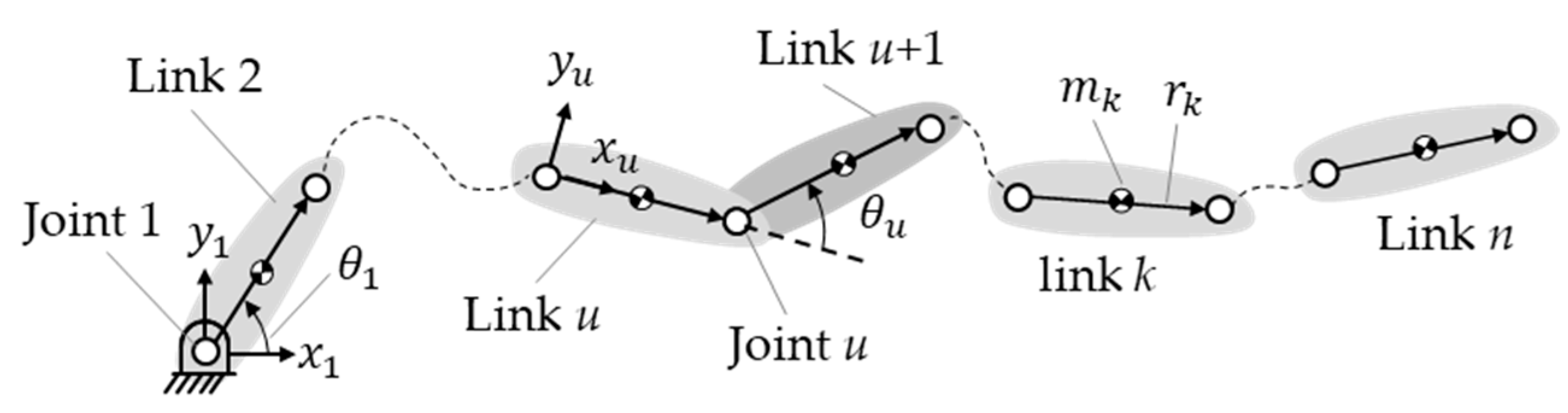
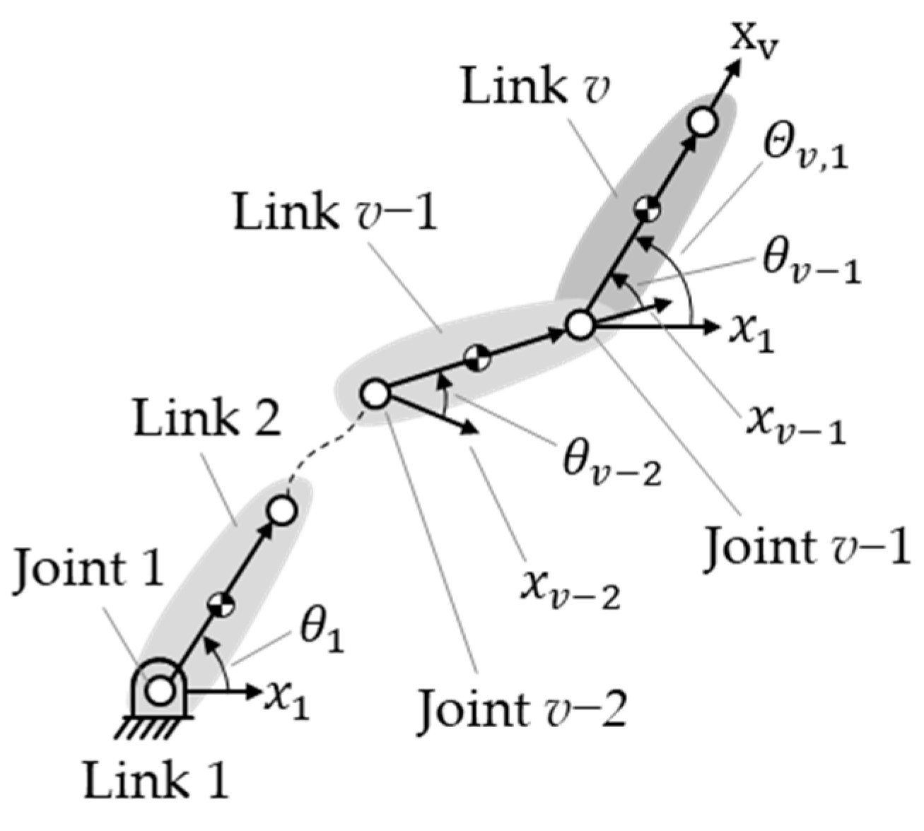
2. Torque Representation at a Typical Joint

For a statically balanced manipulator, it would be ideal to use the springs’ torque contribution to balance the gravitational torque contribution as much as possible. However, when springs counter one another, they also produce internal counter-torques. These torques can be regarded as inefficient for the system. To evaluate the internal counter-torque between springs, it is necessary to formulate the torque contributions of the gravity of the links and springs.

2.1. Torque Contribution Caused by Gravity of a Typical Link at Joint u

Figure 1 shows an n-link serially connected manipulator with revolute joints only. The variables x u and y u are the x- and y -axis coordinates of link u. A typical joint, joint u, is between link u and link u + 1 and is associated with joint angle θ u , which is the angle from the x-axis coordinate of link u to the x-axis coordinate of link u + 1. T ( θ ) is a vector for transforming the coordinates to the coordinate system of the ground link:
T ( θ ) = ( cos θ sin θ )  
P k is the position vector from joint 1 on the ground link to the mass center of a moving link k, and transforming the coordinate system of the links in the position vector to that of the ground link can be expressed as follows:
P k = r 2 T ( Θ 2 , 1 ) + r 3 T ( Θ 3 , 1 ) + + r k 1 T ( Θ k 1 , 1 ) + 1 2 r k T ( Θ k , 1 )  
where r k is the length of link k. Figure 2 shows that Θ v , 1 is the accumulated joint angle of the joints between link v − 1 and link 1, which can be expressed as
Θ v , 1 = θ v 1 + θ v 2 + + θ 1  
Additionally, the position vector can be rewritten as
P k = v = 2 k c v r v T ( Θ v , 1 )  
where c v is the coefficient of the links. For the position vector of link k, only c k is 0.5; the other coefficients are 1.
Based on the vector for transforming the coordinate system and position vector, the potential energy of a typical link, link k, can be expressed as
U g = m k g T ( 270 ° ) · P k  
where m k is the mass of link k, and g is the constant of gravitational acceleration. By substituting Equation (4) into Equation (5), the gravitational potential energy can be rewritten as
U g = m k g T ( 270 ° ) · v = 2 k c v r v T ( Θ v , 1 ) = m k g   v = 2 k c v r v cos ( Θ v , 1 270 ° )
Equation (6) shows that the gravitational potential energy of link k is a function of the set of the accumulated joint angles of the joint between link 2 and link 1, extended sequentially to include all the joints between link k and link 1, i.e., Θ 2 , 1 , Θ 3 , 1 , , Θ k , 1 .
After deriving the formula for the potential energy from the gravity of link k, the torque contribution caused by this potential energy at joint u, according to Lagrangian mechanics, can be expressed as
τ u , g   = U g θ u  
If joint u is the joint between links u and u + 1, link k can be defined in relation to joint u as two potential cases: (a) preceding link u ( k     u ) and (b) succeeding link u ( k   >   u ). In case (a), the gravitational potential energy of link k is a function of the set of accumulated joint angles of all the joints from 1 to k, from those between links 2 and 1 to those between links k and 1. Because k is not greater than u when k is equal to u, the set of the accumulated joint angles Θ 2 , 1 , Θ 3 , 1 , , Θ u , 1 is not a function of joint angle θ u ; therefore, the torque contribution at joint u is zero.
τ u , g   = 0   f o r     k     u    
In case (b), the gravitational potential energy is a function of the set of the accumulated joint angles Θ 2 , 1 , Θ 3 , 1 , , Θ k , 1 . Because k is greater than u, that portion of the energy is a function of the accumulated joint angles of all the joints from 1 to u, from those between links 2 and 1 to those between links u and 1, i.e., Θ 2 , 1 , Θ 3 , 1 , , Θ u , 1 . This is not a function of joint angle θ u , so the torque contribution at joint u of this portion of the energy is zero. The remaining portion of the energy is a function of the accumulated joint angles of all the joints from 1 to k, from those between links u + 1 and 1 to those between links k and 1, i.e., Θ u + 1 , 1 , , Θ k , 1 . This is a function of joint angle θ u . Substituting Equation (6) into Equation (7), we find that the torque contribution at joint u of all the links succeeding link u can be expressed as
τ u , g   = k = u + 1 n m k g v = u + 1 k c v r v sin ( Θ v , 1 270 ° )  
It is worth noting that Equation (9) shows the torque contribution to be a function of the set of the accumulated joint angles of all the joints from 1 to n, from those between links u + 1 and 1 to those between links n and 1, i.e., Θ u + 1 , 1 , , Θ n , 1 .

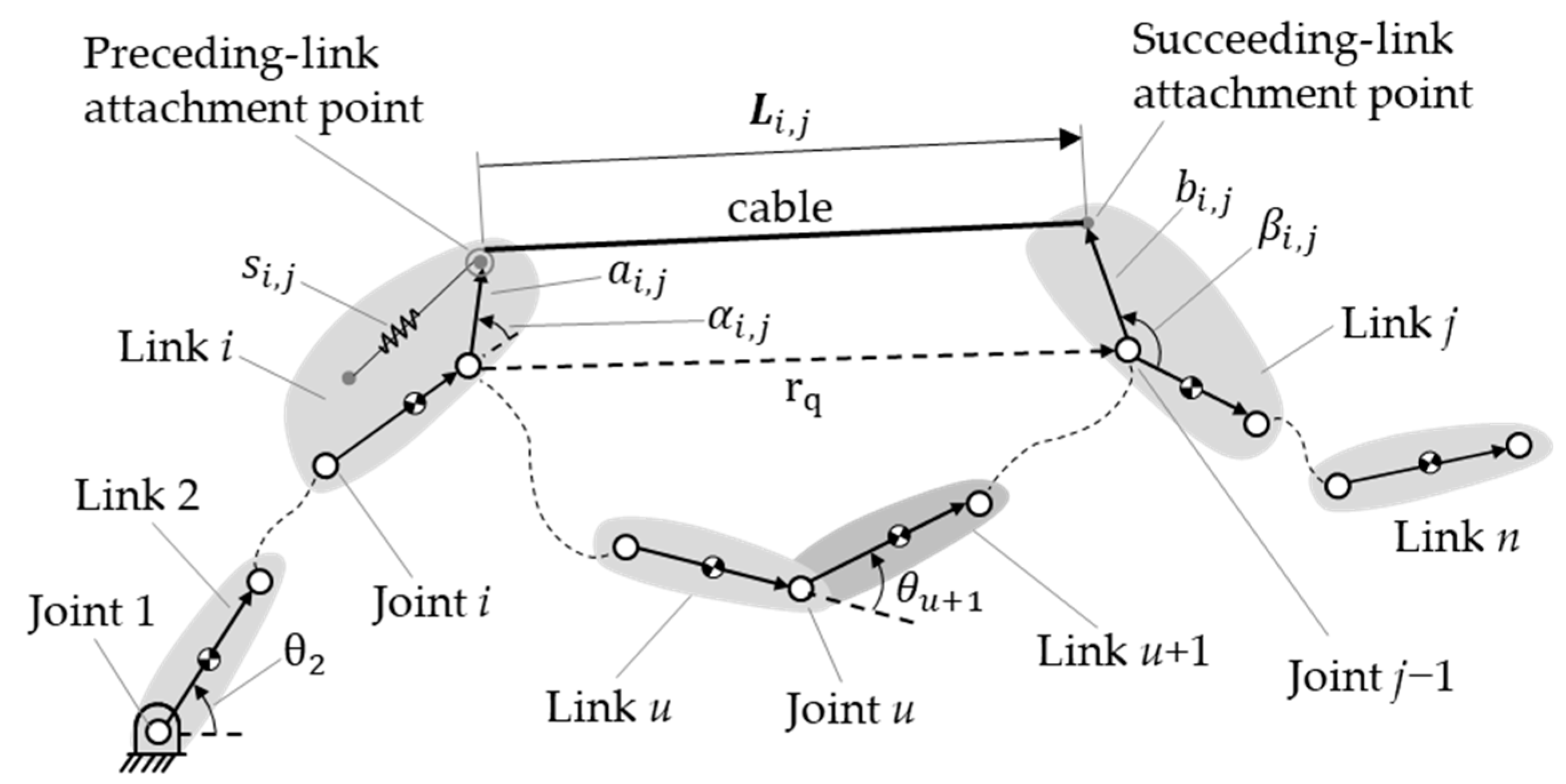
2.2. Torque Contribution Caused by Spring s i , j at Joint u

Figure 3 shows a typical spring, s i , j , in an n-link manipulator. It is assumed that there is at most one spring between any two links. The spring is connected to links i and j, which we define as the preceding and succeeding links, respectively. Further, the spring is connected via a pulley-and-cable arrangement, such that it is a zero-free-length spring [42]. The potential energy of the spring is expressed as
U s = 1 2 k i , j L i , j · L i , j  
where k i , j is the stiffness of the spring, and L i , j   is its displacement from the preceding-link attachment point to the succeeding-link attachment point of the spring; the latter is also the elongation of the spring because of its zero-free-length characteristic. The spring’s displacement is represented as the position vector from joint i to the preceding attachment point of the spring, the vector of the links between the spring’s two attachment points, and the position vector from joint j − 1 to the succeeding attachment point. Transferring these vectors to the coordinate system of the ground link, the spring’s displacement can be expressed as
L i , j = a i , j T ( Θ i , 1 + α i , j ) + [ r i + 1 T ( Θ i + 1 , 1 ) + + r j 1 T ( Θ j 1 , 1 ) ] + b i , j T ( Θ j , 1 + β i , j )  
where r i + 1 to r j 1 are the lengths of the links between the two attached links (from link i + 1 to link j − 1);   a i , j is the length of the preceding link between joint i and the preceding attachment point of the spring; and b i , j is the length of the succeeding link between joint j − 1 and the succeeding attachment point of the spring. These two lengths are a positive constant. The angle α i , j is the angle between link i and the preceding attachment point of the spring; β i , j is the angle between link j to the succeeding attachment point of the spring. These two angles are constant. The angle Θ i , 1   is the accumulated joint angle of all the joints between links i and 1; Θ q , 1   is the accumulated joint angle of all the joints from those between links i + 1 and 1 to those between link j − 1 and link 1; and Θ j , 1 is the accumulated joint angle of all the joints between links j and 1. Substituting Equation (11) into Equation (10), we find that the potential energy of the spring can be rewritten as
U s = W i , j i + v = i + 1 j 1 W i , j v + C i , j  
where W i , j i is the portion of the elastic potential energy that is a function of the set of the accumulated joint angles of all the joints from those between links i + 1 and i to those between links j and i, i.e., Θ i + 1 , i , , Θ j , i .
W i , j i = k i , j a i , j T ( Θ i , 1 + α i , j ) · [ r i + 1 T ( Θ i + 1 , 1 ) + + r j 1 T ( Θ j 1 , 1 ) + b i , j T ( Θ j , 1 + β i , j ) ] = k i , j a i , j [ q = i + 1 j 1 r q cos ( Θ q , i α i , j ) + b i , j cos ( Θ j , i + β i , j α i , j ) ]  
W i , j v   is the portion of the elastic potential energy that is a function of the set of the accumulated joint angles of all the joints from those between links v + 1 and v to those between links j and v, i.e., Θ v + 1 , v , , Θ j , v .
W i , j v = k i , j r v T ( Θ v , 1 ) · [ r v + 1 T ( Θ v + 1 , 1 ) + + r j 1 T ( Θ j 1 , 1 ) + b i , j T ( Θ j , 1 + β i , j ) ] = k i , j r v [ q = v + 1 j 1 r q cos ( Θ q , v α i , j ) + b i , j cos ( Θ j , v + β i , j ) ]
C i , j is the portion of the elastic potential energy that is constant, i.e., it is not a function of any joint angle.
C i , j = 1 2 k i , j ( a i , j 2 + q = i + 1 j 1 r q 2 + b i , j 2 )  
Having derived the formula for the potential energy of spring s i , j , we can express the torque contribution of the potential energy of the spring at joint u as
T u , s = U s θ u  
Spring s i , j can be defined in relation to joint u, which is connected to links u and u + 1 as two potential cases: (a) its connected links, i.e., links i and j, both either precede or succeed link u (i < ju or j > i > u); and (b) link i precedes link u, and link j succeeds it (iu < j). The energy, which is constant, is not a function of the joint angle θ u , as shown in Equation (15); the torque contribution of this energy is zero for both cases. In case (a), the energy is a function of the set of accumulated joint angles Θ i + 1 , i , , Θ j , i and Θ v + 1 , v , , Θ j , v , as shown in Equations (13) and (14). When the links to which the spring is attached precede link u, i.e., i < ju, the energy is a function of the accumulated joint angles of all the joints between the links that precede link u. This energy is not a function of joint angle θ u . When the links to which the spring is attached succeed link u, i.e., j > i > u, the energy is a function of the accumulated joint angles of all the joints between the links that succeed link u. This energy is also not a function of the joint angle θ u . The torque contribution at joint u of the potential energy of spring s i , j is thus zero in case (a).
T u , s = 0   f o r     i   <   j u     o r     j   >   i   >   u  
In case (b), the preceding link of the spring precedes link u and the succeeding link of the spring succeeds link u (iu < j). The elastic potential energy is, thus, a function of the set of accumulated joint angles Θ i + 1 , i , , Θ j , i and Θ v + 1 , v , , Θ j , v . The portion of the energy that is a function of the set of the accumulated joint angles Θ i + 1 , i , , Θ u , i and Θ v + 1 , v , , Θ u , v is not a function of the joint angle θ u ; however, the portion of the energy that is a function of the set of accumulated joint angles Θ u + 1 , i , , Θ j , i and Θ u + 1 , v , , Θ j , v is a function of this joint angle. Substituting Equations (13) and (14) into Equation (16), we find that the torque contribution at joint u of spring s i , j can be expressed as
T u , s = k i , j a i , j [ q = u + 1 j 1 r q sin ( Θ q , i α i , j ) + b i , j sin ( Θ j , i + β i , j α i , j ) ] + k i , j v = i + 1 u r v [ r q sin ( Θ q , v ) + b i , j sin ( Θ j , v + β i , j ) ]         f o r       i     u   <   j      
Equation (18) is, thus, the formula for the torque contribution at joint u of spring s i , j when its preceding link is link u, or when link u is between the links holding the attachment points of the spring.

3. Internal Counter-Torque Classified from Torque Contribution Caused by Springs

Internal counter-torque is defined as the torque caused by springs that are not used to balance gravitational torque but to counter the torque produced by other springs. It can be regarded as waste torque that springs have to produce merely to achieve static balance. Thus, it is desirable to minimize this torque. To determine whether the various torques serve to balance gravitational torque or not, it is necessary to determine whether they have the same accumulated joint angles. The gravitational torque contribution of a typical link and a typical spring were derived in Section 2, and from this, we can derive the classification of the springs’ torque contribution.

3.1. Classification of Torque Contribution Caused by Springs

To reiterate, the torque contribution at joint u caused by the gravity of the links succeeding link u is a function of the set of the accumulated joint angles Θ u + 1 , 1 , , Θ n , 1 . In Equation (18), when i = 1, the first portion of the torque contribution caused by spring s i , j is a function of the set of the accumulated joint angles Θ q , 1 , , Θ j , 1 , which are the angles of the joints between the links succeeding link u and link 1. This torque contribution balances the gravitational torque contribution. The torque contribution of all ground-attached springs (i = 1), i.e., all the springs for which the preceding link is link 1, can be expressed as
E u , s = j = u + 1 n k 1 , j a 1 , j [ q = u + 1 j 1 r q sin ( Θ q , 1 α 1 , j ) + b 1 , j sin ( Θ j , 1 + β 1 , j α 1 , j ) ]  
Equation (19) shows that this torque contribution is a function of the set of the accumulated joint angles of all the joints, from those between links u + 1 and 1 to those between links n and link 1, i.e., Θ u + 1 , 1 , , Θ n , 1 , which is the same as the accumulated joint angles in the formula for the gravitational torque contribution at joint u (Equation (9)).
In Equation (18), the first portion of the torque contribution of all ground-attached springs is used to balance the gravitational torque, as mentioned above. However, the second portion of this torque contribution is a function of the set of the accumulated joint angles Θ q , v , , Θ j , v , which are the angles of the joints between all mobile links. These torque contributions are countered by the torque contributions of other springs. Additionally, in Equation (18), the first and second portions of the torque contributions of all the springs between two mobile links are a function of the set of the accumulated joint angles Θ u + 1 , i , , Θ j , i and Θ q , v , , Θ j , v , which are also the angles of all the joints between mobile links. These torque contributions do not balance the gravitational torque and are defined as the counter-torque effect contribution; they can be expressed as
I u , s = j = u + 1 n k 1 , j v = 2 u r v [ r q sin ( Θ q , v ) + b 1 , j sin ( Θ j , v + β 1 , j ) ] + i = 2 u k i , j a i , j [ q = u + 1 j 1 r q sin ( Θ q , i α i , j ) + b i , j sin ( Θ j , i + β i , j α i , j ) ] + k i , j v = i + 1 u r v [ r q sin ( Θ q , v ) + b i , j sin ( Θ j , v + β i , j ) ] .
Static balance equations are derived by combining the gravitational torque contribution (Equation (9)), the gravity-balancing torque contribution (Equation (19)), and the counter-torque effect contribution (Equation (20)), using the same accumulated joint angles. In Equation (20), if u is equal to 1, i.e., joint 1, there is no counter-torque effect contribution. However, if u is larger, the number of terms in Equation (20) would be more; the counter-torque effect contribution would become larger qualitatively if the joint is farther from the ground. Notably, in numerical calculations, the counter-torque effect contribution does not become larger quantitatively at the joint farther from the ground in some cases, which depends on the workspace and spring-attachment parameters.
The counter-torque contribution shown in Equation (20) can be considered a combination of many sine functions. The summing magnitude of the counter-torque contribution is the maximum possible value for the total counter-torque, assuming that all sine functions reach their maxima at the same configuration. We treated the summing magnitude of the counter-torque contribution as an internal counter-torque, which can be expressed as
Z u = j = u + 1 n k 1 , j v = 2 u r v ( r q + b 1 , j ) + i = 2 u k i , j a i , j ( q = u + 1 j 1 r q + b i , j ) + k i , j v = i + 1 u r v ( r q + b i , j )  
In this study, we assumed the center of mass (CoM) of each link to be on the link itself, at the midpoint of the segment connecting the joints. However, we made this assumption only to simplify the derivation. If the CoM of each link is at a generic point along its length, this would make it too complex to derive the torque contributions of spring installations to achieve static balance only. However, it is still possible to evaluate internal counter-torque in a statically balanced manipulator, because the torque contributions of the springs can also be classified according to whether or not they balance the gravitational torque.

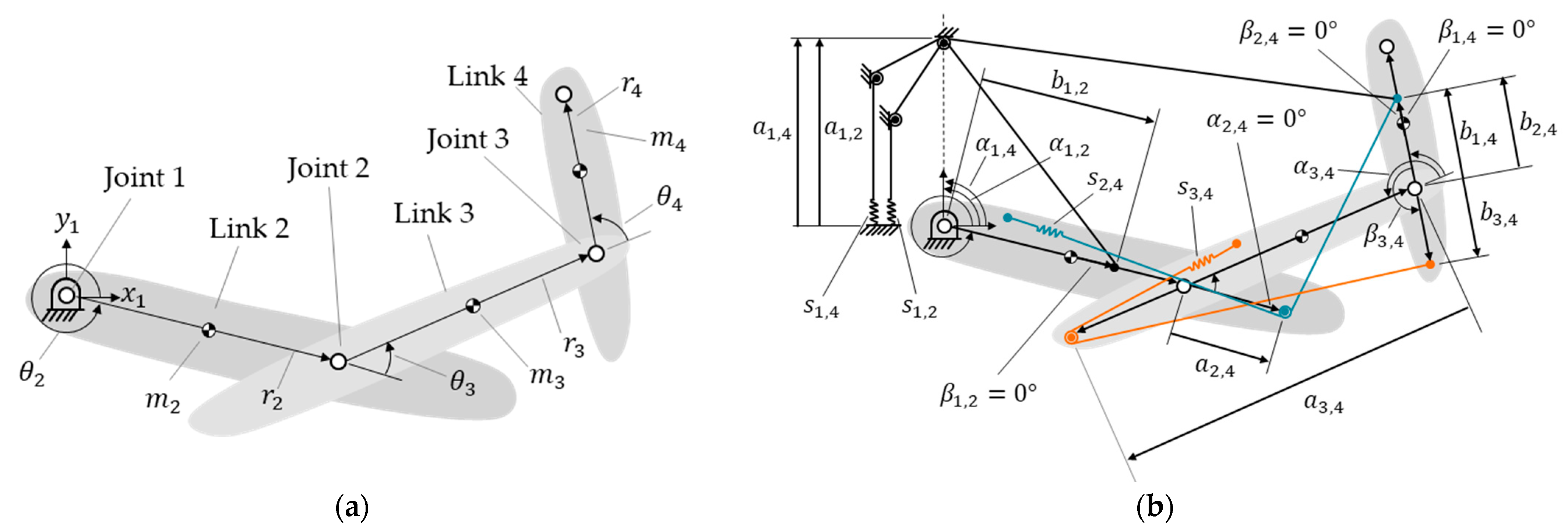
3.2. Internal Counter-Torque of an Illustrative Four-Link Manipulator

For example, Figure 4a shows a four-link manipulator without springs. Figure 4b shows the same manipulator with four springs, s 1 , 4 , s 1 , 2 , s 2 , 4 and s 3 , 4 . These springs are attached via cables and pulleys passing through connected points, allowing them to achieve the zero-free-length characteristic in practice [43,44]. Note that the pulley radii are much smaller than the elongation of the spring and can be disregarded. Springs s 2 , 4 and s 3 , 4 are installed on links 2 and 3 and represented by red and blue colors, respectively, in Figure 4b, to distinguish them.
Joint 1 is between links 1 and 2. Links 2, 3, and 4 follow link 1 and are, thus, case (b). According to Equation (9), the torque contribution at joint 1 caused by these links can be represented as
τ 1 , g   = [ 1 2 m 2 g + m 3 g + m 4 g ] r 2 sin ( Θ 2 , 1 270 ° ) [ 1 2 m 3 g + m 4 g ] r 3 sin ( Θ 3 , 1 270 ° ) 1 2 m 4 g r 4 sin ( Θ 4 , 1 270 ° )
Springs s 2 , 4 and s 3 , 4 , which are attached to the links that follow link 1, are case (a), so their torque contribution at joint 1 is zero. Springs s 1 , 2 and s 1 , 4 , which are attached to link 1, are case (b), and their torque contribution at joint 1 can be calculated using Equation (19):
E 1 , s = k 1 , 2 a 1 , 2 b 1 , 2 sin ( Θ 2 , 1 + β 1 , 2 α 1 , 2 ) k 1 , 4 a 1 , 4 [ r 2 sin ( Θ 2 , 1 α 1 , 4 ) + r 3 sin ( Θ 3 , 1 α 1 , 4 ) + b 1 , 4 sin ( Θ 4 , 1 + β 1 , 4 α 1 , 4 ) ]
The static balance equations are created by combining Equations (22) and (23), using the same accumulated joint angle, as follows:
k 1 , 2 a 1 , 2 b 1 , 2 sin ( Θ 2 , 1 + β 1 , 2 α 1 , 2 ) + k 1 , 4 a 1 , 4 r 2 sin ( Θ 2 , 1 α 1 , 4 ) + ( 1 2 m 2 g + m 3 g + m 4 g ) r 2 sin ( Θ 2 , 1 270 ° ) = 0    
k 1 , 4 a 1 , 4 r 3 sin ( Θ 3 , 1 α 1 , 4 ) + ( 1 2 m 3 g + m 4 g ) r 3 sin ( Θ 3 , 1 270 ° ) = 0
k 1 , 4 a 1 , 4 b 1 , 4 sin ( Θ 4 , 1 + β 1 , 4 α 1 , 4 ) + 1 2 m 4 g r 4 sin ( Θ 4 , 1 270 ° ) = 0
The sine functions in Equations (24)–(26) should cause the signs of the terms to be opposite, so the attachment angles of the springs can be calculated. All the torque contributions of springs s 1 , 2 and s 1 , 4 are functions of Θ 2 , 1 , Θ 3 , 1 , and Θ 4 , 1 , which are used for balancing the gravitational torque contribution. Thus, the internal counter-torque at joint 1 is zero.
Joint 2 is between link 2 and link 3; therefore, link 2 is case (a), since it does not follow link 2; links 3 and link 4, which follow link 2, are case (b). Based on Equation (9), the torque contribution at joint 2 of these links can be calculated as follows:
τ 2 , g   = [ 1 2 m 3 g + m 4 g ] r 3 sin ( Θ 3 , 1 270 ° ) 1 2 m 4 g r 4 sin ( Θ 4 , 1 270 ° )  
Springs s 1 , 2 and s 3 , 4 , which are attached to links that both precede or follow link 2, are case (a). Their torque contribution at joint 2 is, thus, zero. Springs s 1 , 4 and s 2 , 4 , whose preceding link is either link 2 itself or a link before link 2 (i.e., link 2 is between the links to which the spring is attached) are case (b). Therefore, based on Equations (19) and (20), their torque contribution at joint 2 can be calculated as follows:
E 2 , s   = k 1 , 4 a 1 , 4 [ r 3 sin ( Θ 3 , 1 α 1 , 4 ) + b 1 , 4 sin ( Θ 4 , 1 + β 1 , 4 α 1 , 4 ) ]  
I 2 , s = k 1 , 4 r 2 [ r 3 sin ( Θ 3 , 2 ) + b 1 , 4 sin ( Θ 4 , 2 + β 1 , 4 ) ] k 2 , 4 a 2 , 4 [ r 3 sin ( Θ 3 , 2 ) + b 2 , 4 sin ( Θ 4 , 2 + β 2 , 4 α 2 , 4 ) ]  
The static balance equations are created by combining Equations (27)–(29), using the same accumulated joint angle, as follows:
k 1 , 4 a 1 , 4 r 3 sin ( Θ 3 , 1 α 1 , 4 ) + ( 1 2 m 3 g + m 4 g ) r 3 sin ( Θ 3 , 1 270 ° ) = 0
k 1 , 4 a 1 , 4 b 1 , 4 sin ( Θ 4 , 1 + β 1 , 4 α 1 , 4 ) + 1 2 m 4 g r 4 sin ( Θ 4 , 1 270 ° ) = 0
k 1 , 4 r 2 r 3 sin ( Θ 3 , 2 ) k 2 , 4 a 2 , 4 r 3 sin ( Θ 3 , 2 α 2 , 4 ) = 0  
k 1 , 4 b 1 , 4 r 2 sin ( Θ 4 , 2 + β 1 , 4 ) k 2 , 4 a 2 , 4 b 2 , 4 sin ( Θ 4 , 2 + β 2 , 4 α 2 , 4 ) = 0
Note that, for joint 2, the static balance equations, which are functions of the accumulated joint angles Θ 3 , 1 and Θ 4 , 1 (Equations (30) and (31)), are the same as Equations (25) and (26). The sine functions in Equations (32) and (33) should cause the signs of the terms to be opposite, so the attachment angles of the springs can be calculated. The internal counter-torques of springs s 1 , 4 and s 2 , 4 are equal to the magnitude of the terms from Equation (29), and replacing k 1 , 4 , k 2 , 4 , b 1 , 4 , b 2 , 4 with the static balance Equation (30) to Equation (33) will cancel them out under the sine function. The internal counter-torque can, thus, be calculated using Equation (21), as follows:
Z 2 = k 1 , 4 r 2 r 3 + k 1 , 4 r 2 b 1 , 4 + k 2 , 4 a 2 , 4 r 3 + k 2 , 4 a 2 , 4 b 2 , 4 = r 2 a 1 , 4 ( m 4 g r 4 + ( m 3 g r 3 + 2 m 4 g r 3 ) )
Equation (34) shows that the internal counter-torque at joint 2 is a function of the preattachment length of spring s 1 , 4 .
Joint 3 is between link 3 and link 4. Links 2 and 3, therefore, are case (a), while link 4 is case (b). Based on Equation (9), the torque contribution at joint 3 of link 4 can be calculated as follows:
τ 3 , g   = 1 2 m 4 g r 4 sin ( Θ 4 , 1 270 ° )  
Spring s 1 , 2 , which connects the links that precede link 3, is case (a), and its torque contribution at joint 3 is zero. Springs s 1 , 4 , s 2 , 4 , and s 3 , 4 , for which the preceding link is link 3, or link 3 is between the links to which they are attached, are case (b). Based on Equations (19) and (20), their torque contributions at joint 3 can be calculated as follows:
E 3 , s   = k 1 , 4 a 1 , 4 b 1 , 4 sin ( Θ 4 , 1 + β 1 , 4 α 1 , 4 )
I 3 , s = k 1 , 4 b 1 , 4 [ r 2 sin ( Θ 4 , 2 + β 1 , 4 ) + r 3 sin ( Θ 4 , 3 + β 1 , 4 ) ] k 2 , 4 b 2 , 4 [ a 2 , 4 sin ( Θ 4 , 2 + β 2 , 4 α 2 , 4 ) r 3 sin ( Θ 4 , 3 + β 2 , 4 ) ] k 3 , 4 a 3 , 4 b 3 , 4 sin ( Θ 4 , 3 + β 3 , 4 α 3 , 4 )
The static balance equations are created by combining Equations (35)–(37), using the same accumulated joint angle, as follows:
k 1 , 4 a 1 , 4 b 1 , 4 sin ( Θ 4 , 1 + β 1 , 4 α 1 , 4 ) + 1 2 m 4 g r 4 sin ( Θ 4 , 1 270 ° ) = 0
k 1 , 4 b 1 , 4 r 2 sin ( Θ 4 , 2 + β 1 , 4 ) k 2 , 4 a 2 , 4 b 2 , 4 sin ( Θ 4 , 2 + β 2 , 4 α 2 , 4 ) = 0
k 1 , 4 b 1 , 4 r 3 sin ( Θ 4 , 3 + β 1 , 4 ) + k 2 , 4 b 2 , 4 r 3 sin ( Θ 4 , 3 + β 2 , 4 ) k 3 , 4 a 3 , 4 b 3 , 4 sin ( Θ 4 , 3 + β 3 , 4 α 3 , 4 ) = 0
Note that the static balance equations, which are a function of the accumulated joint angles Θ 4 , 1 and Θ 4 , 2 (Equations (38) and (39)), are the same as Equations (31) and (33). The sine functions in Equation (40) should cause the signs of the terms to be opposite. The internal counter-torques of springs s 1 , 4 and s 2 , 4 are equal to the magnitude of the terms from Equation (37), and replacing k 1 , 4 , k 2 , 4 , k 3 , 4 , b 1 , 4 , b 2 , 4 , and b 3 , 4 with the static balance Equations (30)–(33) and (40) will cancel them out under the sine function. The internal counter-torque at joint 3 can thus be calculated using Equation (21), as follows:
Z 3 = k 1 , 4 r 2 b 1 , 4 + k 1 , 4 r 3 b 1 , 4 + k 2 , 4 a 2 , 4 b 2 , 4 + k 2 , 4 r 3 b 2 , 4 + k 3 , 4 a 3 , 4 b 3 , 4 = [ r 2 a 1 , 4 + r 3 a 1 , 4 + 1 2 ( r 2 a 1 , 4 + 1 ) r 3 a 2 , 4 ] ( m 4 g r 4 )
Equation (41) shows that the internal counter torque at joint 3 is a function of the preattachment lengths of springs s 1 , 4 and s 2 , 4 .

4. Minimum of Internal Counter-Torque of a Statically Balanced Manipulator

Definitely, there is an advanced optimization method that can be used such as multiobjective optimization. In this study, to reduce the complexity of the two-objective optimization problem, the two objective functions are summed using a simple approach. The internal counter-torques at joints 2 and 3 are functions of the preattachment lengths of springs s 1 , 4   and s 2 , 4 . The following equation can, therefore, be used to minimize internal counter-torque, assuming that the sum of internal counter-torques in an objective function is as follows:
Z s = Z 2 + Z 3 = r 2 a 1 , 4 ( m 3 g r 3 + 2 m 4 g r 3 ) + [ 2 r 2 a 1 , 4 + r 3 a 1 , 4 + 1 2 ( r 2 a 1 , 4 + 1 ) r 3 a 2 , 4 ] ( m 4 g r 4 )  
Spring s 1 , 2 is independent of the internal counter-torque at joints 2 and 3, as shown in Equations (34) and (41). Because these internal counter-torques are functions of the preattachment lengths of springs s 1 , 4 and s 2 , 4 , these lengths are normalized according to the preattachment length of spring s 1 , 2 , which can be expressed as follows:
x 1 , 4 = a 1 , 2 a 1 , 4  
x 2 , 4 = a 1 , 2 a 2 , 4
Because the sum of the lengths of the links in the manipulator is 3.2 times the preattachment length of s 1 , 2 , to avoid having the attachment point of the ground-attached spring s 1 , 4 installed outside the range formed by all the straight links in the vertical direction from the ground, the normalized coefficient of the spring is constrained to be within the range of 0–3.2. For spring s 2 , 4 , which is between links 2 and 4, the preceding attachment point cannot be installed anywhere other than link 2. The normalized coefficient for this spring is, therefore, restricted to the range of 0–1.
As an example, we ran an optimization procedure on a previously described four-link manipulator. The link properties of the manipulator are shown in Table 1, adopted from [45]. To perform the optimization procedure, we used MATLAB (with the fminsearch function) and a computer with a CPU with the following specifications: 12th Gen Intel(R) Core(TM) i9-12900K 3.19 GHz, and 32 GB RAM. The time taken to run the optimization procedure was 3.2 min. The preselected and optimized attachment angles and lengths are shown in Table 2 and Table 3. The optimized normalized coefficients of springs s 1 , 4 and s 2 , 4 were 2.29. and 0.71, respectively. Their preceding lengths were obtained by substituting these coefficients into Equations (43) and (44); the stiffness and preattachment lengths of springs s 1 , 4 , s 2 , 4 , and s 3 , 4 were obtained using the static balance equations (Equations (24)–(26), (30)–(33) and (38)–(40)), as shown in Table 2. Table 3 shows that the optimized stiffness of springs s 1 , 4 and s 2 , 4 were 443 N/m and 1713 N/m less than the preselected value, respectively. The optimized preattachment lengths of springs s 1 , 4 and s 2 , 4 were, respectively, 0.69 m and 0.21 m longer than the preselected lengths, and that of spring s 3 , 4 was 0.12 m shorter. The peak magnitude of the internal counter-torques at joint 2 and joint 3 were, respectively, reduced by 28% (from 392   N · m   to 282 N · m ) and 50% (from 429 N · m to 215 N · m ) after optimization. The total peak magnitude of the internal counter-torque was, thus, reduced by 57% (from 821 N · m to 497 N · m ).
We substituted the values from Table 1 and Table 2 into the static balance equations (Equations (24)–(26), (30)–(33) and (38)–(40)) and into the internal counter-torque at joints 2 and 3 (Equations (34) and (41)) and found that the sine functions did not cancel them out. The torque contributions of the springs that balance the gravitational torque and the internal counter-torque at the joints could, therefore, be simulated using the accumulated joint angles, which were in the range of 0–360° (Figure 5).
To further investigate the relative magnitude of these torques, we evaluated the torque contributions of ground-attached springs used for balancing gravitational torques and found that they were maintained regardless of whether the preselected or adjusted spring attachment parameters were used in the static balance equations. At each joint, if the joint was closer to link 1 (the ground link), the magnitudes of the torque contributions of both gravity and the spring at that joint were larger. At joint 1, the internal counter-torque caused by the springs was zero. At joint 2, the optimized internal counter-torque was larger than that at joint 3. The torque contribution ratio of the internal counter-torque to the gravitational balancing torque at joint 2 was lower than that at joint 3, however. This result showed that the internal counter-torques at the joints could be significantly reduced by adjusting the attachment points of the springs but maintaining the static-balancing conditions of the manipulator as a whole.

5. Conclusions

This paper presents an evaluation of the internal counter-torque produced by springs in statically balanced manipulators. Some of the torque contributions of ground-attached springs are used to balance the gravitational torque. Other torque contributions counter the torque contributions of the non-ground-attached springs; these are the internal counter-torques. (1) The torque contribution of a spring at joint 1 is a function of the accumulated joint angles of the joints between the ground link and a mobile link only. This torque must balance the gravitational torque because it has the same accumulated joint angle as the gravitational torque. Thus, the joint that is connected to the ground does not have any internal counter-torque. (2) The internal counter-torque on other joints could be substantially reduced by adjusting the attachment lengths of the springs installed. In the three-DOF case of this paper, we found that there were 28% and 50% reductions at joints 2 and 3, respectively. (3) This evaluation can be applied to any planar serially connected manipulator with any configuration of springs installed according to the systematic balancing method. By following this process of determining the torque contributions at the joints, the internal counter-torque can be calculated. (4) This study highlights the concept and evaluation of the internal counter-torque and shows that when designing manipulators, the internal counter-torque should be considered in addition to static balancing. Less internal counter-torque can reduce the tension in the manipulator and the forces applied to its joints and links. (5) Future work based on this study may involve expanding on this method to derive a more general model in which the CoM of each link is considered not along its length, as well as the multi-objective optimization of internal counter-torques with different spring configurations under the same static-balancing condition, and experiments designed for verifying the effect of the reduction in the internal counter-torque.

Author Contributions

Conceptualization, C.-S.J. and D.-Z.C.; methodology, C.-S.J., C.-W.J. and D.-Z.C.; software, C.-S.J. and C.-H.S.; writing—original draft preparation, C.-S.J. and C.-W.J.; writing—review and editing, C.-S.J.; visualization, C.-S.J. All authors have read and agreed to the published version of the manuscript.

Funding

This research was funded by the Ministry of Science and Technology (grant number 109-2221-E-002-002-MY3), Taiwan; and funded for English editing by National Taiwan University under the Excellence Improvement Program for Doctoral Students (grant number 108-2926-I-002-002-MY4), sponsored by National Science and Technology Council, Taiwan.

Data Availability Statement

Not applicable.

Conflicts of Interest

The authors declare no conflict of interest.

References

  1. Hockstein, N.G.; Nolan, J.P.; O’Malley, B.W.; Woo, Y.J. Robotic microlaryngeal surgery: A technical feasibility study using the daVinci surgical robot and an airway mannequin. Laryngoscope 2005, 115, 780–785. [Google Scholar] [CrossRef] [PubMed]
  2. Wang, W.; Li, J.; Wang, S.; Su, H.; Jiang, X. System design and animal experiment study of a novel minimally invasive surgical robot. Int. J. Med. Robot. Comput. Assist. Surg. 2016, 12, 73–84. [Google Scholar] [CrossRef] [PubMed]
  3. Lin, P.Y.; Shieh, W.B.; Chen, D.Z. A theoretical study of weight-balanced mechanisms for design of spring assistive mobile arm support (MAS). Mech. Mach. Theory 2013, 61, 156–167. [Google Scholar] [CrossRef]
  4. Zhou, L.B.; Chen, W.H.; Chen, W.J.; Bai, S.P.; Zhang, J.B.; Wang, J.H. Design of a passive lower limb exoskeleton for walking assistance with gravity compensation. Mech. Mach. Theory 2020, 150, 103840. [Google Scholar] [CrossRef]
  5. Zhou, L.L.; Bai, S.P.; Andersen, M.S.; Rasmussen, J. Modeling and Design of a Spring-loaded, Cable-driven, Wearable Exoskeleton for the Upper Extremity. Model. Identif. Control 2015, 36, 167–177. [Google Scholar] [CrossRef]
  6. Dewi, T.; Nurmaini, S.; Risma, P.; Oktarina, Y.; Roriz, M. Inverse kinematic analysis of 4 DOF pick and place arm robot manipulator using fuzzy logic controller. Int. J. Electr. Comput. Eng. 2020, 10, 1376–1386. [Google Scholar] [CrossRef]
  7. Stenmark, M.; Malec, J. Knowledge-based instruction of manipulation tasks for industrial robotics. Robot. Comput.-Integr. Manuf. 2015, 33, 56–67. [Google Scholar] [CrossRef]
  8. Martini, A.; Troncossi, M.; Rivola, A. Algorithm for the static balancing of serial and parallel mechanisms combining counterweights and springs: Generation, assessment and ranking of effective design variants. Mech. Mach. Theory 2019, 137, 336–354. [Google Scholar] [CrossRef]
  9. Segla, S. Static balancing of robot mechanisms and manipulation devices. Stroj. Časopis—J. Mech. Eng. 2018, 68, 77–90. [Google Scholar] [CrossRef]
  10. Hoevenaars, A.G.L.; Gosselin, C.; Lambert, P.; Herder, J.L. A Systematic Approach for the Jacobian Analysis of Parallel Manipulators with Two End-Effectors. Mech. Mach. Theory 2017, 109, 171–194. [Google Scholar] [CrossRef]
  11. Baradat, C.; Arakelian, V.; Briot, S.; Guegan, S. Design and prototyping of a new balancing mechanism for spatial parallel manipulators. J. Mech. Design 2008, 130, 072305. [Google Scholar] [CrossRef]
  12. Cho, C.H.; Lee, W. Design of a static balancer with equivalent mapping. Mech. Mach. Theory 2016, 101, 36–49. [Google Scholar] [CrossRef]
  13. Lu, Q.; Ortega, C.; Ma, O. Passive gravity compensation mechanisms: Technologies and applications. Recent Pat. Eng. 2011, 5, 32–44. [Google Scholar] [CrossRef]
  14. Kazerooni, H. Statically balanced direct drive manipulator. Robotica 1989, 7, 143–149. [Google Scholar] [CrossRef]
  15. Rahman, T.; Ramanathan, R.; Seliktar, R.; Harwin, W. A Simple Technique to Passively Gravity-Balance Articulated Mechanisms. ASME J. Mech. Des. 1995, 117, 655–658. [Google Scholar] [CrossRef]
  16. Koser, K. A cam mechanism for gravity-balancing. Mech. Res. Commun. 2009, 36, 523–530. [Google Scholar] [CrossRef]
  17. Simionescu, I.; Ciupitu, L. The static balancing of the industrial robot arms: Part II: Continuous balancing. Mech. Mach. Theory 2000, 35, 1299–1311. [Google Scholar] [CrossRef]
  18. Chu, Y.-L.; Kuo, C.-H. A single-degree-of-freedom self-regulated gravity balancer for adjustable payload. J. Mech. Robot. 2017, 9, 021006. [Google Scholar] [CrossRef]
  19. Ulrich, N.; Kumar, V. Passive mechanical gravity compensation for robot manipulators. In Proceedings of the IEEE International Conference on Robotics and Automation, Sacramento, CA, USA, 9–11 April 1991; Volume 2, pp. 1536–1541. [Google Scholar] [CrossRef]
  20. Agrawal, S.K.; Fattah, A. Gravity-balancing of spatial robotic manipulators. Mech. Mach. Theory 2004, 39, 1331–1344. [Google Scholar] [CrossRef]
  21. Deepak, S.R.; Ananthasuresh, G. Perfect static balance of linkages by addition of springs but not auxiliary bodies. J. Mech. Robot. 2012, 4, 021014. [Google Scholar] [CrossRef]
  22. Simionescu, I.; Ciupitu, L. The static balancing of the industrial robot arms: Part I: Discrete balancing. Mech. Mach. Theory 2000, 35, 1287–1298. [Google Scholar] [CrossRef]
  23. Deepak, S.R.; Ananthasuresh, G.K. Static balancing of spring-loaded planar revolute-joint linkages without auxiliary links. In Proceedings of the 14th National Conference on Machines and Mechanisms (NaCoMM09), Durgapur, India, 17–18 December 2009; pp. 37–44. [Google Scholar]
  24. Franchetti, D.; Boschetti, G.; Lenzo, B. Passive Gravity Balancing with a Self-Regulating Mechanism for Variable Payload. Machines 2021, 9, 145. [Google Scholar] [CrossRef]
  25. Mottola, G.; Cocconcelli, M.; Rubini, R.; Carricato, M. Gravity Balancing of Parallel Robots by Constant-Force Generators. In Gravity Compensation in Robotics; Mechanisms and Machine Science; Arakelian, V., Ed.; Springer: Cham, Switzerland, 2022; pp. 229–273. [Google Scholar] [CrossRef]
  26. Nguyen, V.L. Realization of a Gear-Spring Balancer With Variable Payloads and Its Application to Serial Robots. ASME J. Mech. Robot. 2023, 15, 041013. [Google Scholar] [CrossRef]
  27. Lee, Y.Y.; Chen, D.Z. Determination of spring installation configuration on statically balanced planar articulated manipulators. Mech. Mach. Theory 2014, 74, 319–336. [Google Scholar] [CrossRef]
  28. Tschiersky, M.; Hekman, E.E.; Herder, J.L.; Brouwer, D.M. Gravity Balancing Flexure Spring Mechanisms for Shoulder Support in Assistive Orthoses. IEEE Trans. Med. Robot. Bionics 2022, 4, 448–459. [Google Scholar] [CrossRef]
  29. Hsiu, W.H.; Syu, F.C.; Kuo, C.H. Design and implementation of a new statically balanced mechanism for slider-type desktop monitor stands. Proc. Inst. Mech. Eng. Part C—J. Mech. Eng. Sci. 2015, 229, 1671–1685. [Google Scholar] [CrossRef]
  30. Kuo, C.H.; Lai, S.J. Design of a Novel Statically Balanced Mechanism for Laparoscope Holders With Decoupled Positioning and Orientating Manipulation. J. Mech. Robot. 2016, 8, 015001. [Google Scholar] [CrossRef]
  31. Kamenskii, V. On the question of the balancing of plane linkages. J. Mech. 1968, 3, 303–322. [Google Scholar] [CrossRef]
  32. Raghu, E.; Balasubramonian, A. Experimental study on the elastodynamic behavior of the unbalanced and the counterweighted four bar mechanisms. J. Mech. Des. 1990, 112, 271–277. [Google Scholar] [CrossRef]
  33. Liu, G.; Liu, Y.; Goldenberg, A.A. Design, analysis, and control of a spring-assisted modular and reconfigurable robot. IEEE/ASME Trans. Mechatron. 2010, 16, 695–706. [Google Scholar] [CrossRef]
  34. Liao, K.; Huang, Q.; Fang, Y.; Zhu, J. Study on the Combined Spring Balance Technology Based on Multi-Axis Servo System. In Proceedings of the 4th International Conference on Intelligent Information Processing, Guilin, China, 16–17 November 2019; pp. 132–139. [Google Scholar] [CrossRef]
  35. Martini, A.; Troncossi, M.; Carricato, M.; Rivola, A. Elastodynamic behavior of balanced closed-loop mechanisms: Numerical analysis of a four-bar linkage. Meccanica 2014, 49, 601–614. [Google Scholar] [CrossRef]
  36. Xu, L.-X.; Li, Y.-G. Investigation of joint clearance effects on the dynamic performance of a planar 2-DOF pick-and-place parallel manipulator. Robot. Comput.-Integr. Manuf. 2014, 30, 62–73. [Google Scholar] [CrossRef]
  37. Ludovico, D.; Guardiani, P.; Lasagni, F.; Lee, J.; Cannella, F.; Caldwell, D.G. Design of Non-Circular Pulleys for Torque Generation: A Convex Optimisation Approach. IEEE Robot. Autom. Lett. 2021, 6, 958–965. [Google Scholar] [CrossRef]
  38. Coelho, T.A.H.; Yong, L.; Alves, V.F.A. Decoupling of dynamic equations by means of adaptive balancing of 2-dof open-loop mechanisms. Mech. Mach. Theory 2004, 39, 871–881. [Google Scholar] [CrossRef]
  39. Vezvari, M.R.; Nikoobin, A.; Ghoddosian, A. Perfect torque compensation of planar 5R parallel robot in point-to-point motions, optimal control approach. Robotica 2021, 39, 1163–1180. [Google Scholar] [CrossRef]
  40. Arakelian, V.; Le Baron, J.; Mottu, P. Torque minimisation of the 2-DOF serial manipulators based on minimum energy consideration and optimum mass redistribution. Mechatronics 2011, 21, 310–314. [Google Scholar] [CrossRef]
  41. de Jong, J.J.; Aarts, R.G.K.M. Static Balance of a Flexure-Based Four-Bar Mechanism: Less Torque with More Preload. In RAAD 2022: Advances in Service and Industrial Robotics, Proceedings of the 31st International Conference on Robotics in Alpe-Adria Danube Region, Klagenfurt, Austria, 8–10 June 2022; Mechanisms and Machine Science; Müller, A., Brandstötter, M., Eds.; Springer: Cham, Switzerland, 2022; pp. 306–313. [Google Scholar] [CrossRef]
  42. Delissen, A.A.; Radaelli, G.; Herder, J.L. Design and optimization of a general planar zero free length spring. Mech. Mach. Theory 2017, 117, 56–77. [Google Scholar] [CrossRef]
  43. Ou, Y.H.; Chen, D.Z. Compact Arrangements of Cable-Pulley Type Zero-Free-Length Springs. J. Mech. Robot. 2017, 9, 044502. [Google Scholar] [CrossRef]
  44. Barents, R.; Schenk, M.; van Dorsser, W.D.; Wisse, B.M.; Herder, J.L. Spring-to-Spring Balancing as Energy-Free Adjustment Method in Gravity Equilibrators. J. Mech. Des. 2011, 133, 061010. [Google Scholar] [CrossRef]
  45. Juang, C.W.; Jhuang, C.S.; Chen, D.Z. Spring efficiency assessment and efficient use of spring methods of statically balanced planar serial manipulators with revolute joints only. Mech. Sci. 2022, 13, 817–830. [Google Scholar] [CrossRef]
Figure 1. A typical joint u in an n-link manipulator.
Machines 11 00200 g001
Figure 2. Accumulated joint angles from joints between link v and link 1.
Machines 11 00200 g002
Figure 3. A typical spring s i , j in an n-link manipulator.
Machines 11 00200 g003
Figure 4. A 4-link manipulator: (a) without spring; (b) with four springs: s 1 , 4 , s 1 , 2 , s 2 , 4 , and s 3 , 4 .
Machines 11 00200 g004
Figure 5. Gravitational torque, torque caused by springs balancing gravitational torque and internal counter-torque at (a) joint 1, (b) joint 2, and (c) joint 3.
Machines 11 00200 g005aMachines 11 00200 g005b
Table 1. Link properties of the 4-link manipulator.
m 2   ( kg ) m 3   ( kg ) m 4   ( kg ) r 2   ( m ) r 3   ( m ) r 4   ( m )
2526180.360.450.30
Table 2. Preselected attachment angles and post-attachment length of springs.
α 1 , 2   ( ° ) α 1 , 4   ( ° ) α 2 , 4   ( ° ) α 3 , 4   ( ° ) β 1 , 2   ( ° ) β 1 , 4   ( ° ) β 2 , 4   ( ° ) β 3 , 4   ( ° ) b 1 , 2   ( m ) b 1 , 4   ( m ) b 2 , 4   ( m ) b 3 , 4   ( m )
909001800001800.300.090.090.25
Table 3. Preselected and optimized spring stiffness, spring preattachment length, and peak magnitude of internal counter-torque.
k 1 , 2   ( N / m ) k 1 , 4   ( N / m ) k 2 , 4   ( N / m ) k 3 , 4   ( N / m ) a 1 , 2   ( m ) a 1 , 4   ( m ) a 2 , 4   ( m ) a 3 , 4   ( m ) Z 1   ( N · m ) Z 2  
( N · m )
Z 3  
( N · m )
Z s  
( N · m )
Preselected10011014364918280.300.400.100.400392429821
Optimized44317130.690.210.18282215497
Disclaimer/Publisher’s Note: The statements, opinions and data contained in all publications are solely those of the individual author(s) and contributor(s) and not of MDPI and/or the editor(s). MDPI and/or the editor(s) disclaim responsibility for any injury to people or property resulting from any ideas, methods, instructions or products referred to in the content.

