Abstract
To date, hydraulic energy is still, among the renewable ones, the most widespread and most exploited to produce electricity. With the current trend to exploit any renewable source available, the limits for the economic convenience of hydroelectric power plants have significantly changed, making it interesting and convenient to use even small heads and low flow rates. In the specific applications of hydraulic turbines operating with low heads, the Kaplan turbine plays the predominant role among the available machines, also given the possibility of carrying out an “on cam” regulation, acting simultaneously on the geometry of the rotor and distributor rows, thus allowing a wide flow rate adjustment range. However, for applications characterized by very low heads and low available powers, it may not be convenient to use complex regulating devices. For this reason, these plants usually use axial machines characterized by a partial regulation (of the distributor or of the rotor), significantly reducing the operating range of the machine compared to the case of double regulation. In the last decade, the development of reliable and less expensive permanent magnet generators and power electronic converters and related new control strategies has paved the way for the concept of regulating hydraulic turbines by means of variable rotational speed. This regulation principle is based on the possibility of acting in the case of using synchronous permanent magnets electric generators and electronic power converters and on the variation of the rotational speed of the machine while keeping the grid frequency constant. The concept can be applied both to pure propellers with fixed a rotor and fixed distributor and to hydraulic axial turbines with regulation based on the modification of the variable guide vane opening angle. Although this new regulation approach, even in the case of the combined guide vane and rotational speed regulation, does not allow to recover most of the energy losses due to the variation of the operating conditions as effectively as the Kaplan double regulation does, the variation of the rotation speed, coupled with the variation of the opening of the distributor row, allows to reduce the tangential kinetic energy losses generated at the turbine exit during the off-design operations of a fixed blade opening angle rotor. At the same time, this type of regulation offers a simple and thus low-cost solution. The present study develops the theory underlying this regulation concept, based on the use of the turbomachinery fundamental equations, and reports the results of the off-design CFD analysis carried out for different combinations of rotation speeds and openings of the distributor, showing the improvement of the hydraulic efficiency over a large range of operating conditions with respect to the single regulation approach.
1. Introduction
Hydraulic energy remains the most diffused among the renewable energy sources [1] due to the good availability of the conversion fluid employed, water, the lowest life cycle environmental impact in the case of small power plants, and the highest specific energy conversion system among the renewables. Large hydraulic power plants under low heads (below 40 m, approximately) employ Kaplan turbines, which present an incomparable quality in regulating the flow rate over a wide range of operating conditions (usually from 30% to 110% of the nominal flow rate) due to the simultaneous “on cam” regulation of guide vanes and rotor blades. However, nowadays, with the tendency to exploit any available hydraulic energy source, very low net heads (below 6 m) have started to be taken in consideration for the hydraulic energy conversion in small scale [2]. In this case, the Kaplan turbine architecture with its double regulation may not be economically sustainable without simplifications of the mechanical components and turbine architecture, also involving the regulation mechanisms.
Tubular axial turbines (TAT), with a simplified regulation based on a single guide vane variable opening angle or, as an alternative, a runner blade variable opening angle, are being widely employed. In this case, the main drawback is a significant reduction in the operating range. Over the past decade, several turbines that target the sub 1-MW in-conduit hydroelectric market have been developed and studied [3]. However, adoption of small hydropower technologies remains limited in the water and wastewater utility sector, possibly due to a lack of market penetration and exposure. When possible, because of the permanence over the year of the available flow rate, ultra-compact, simplified, and low-cost hydraulic turbines without regulation have been developed [4] by the main hydraulic turbine manufacturers. See, for instance, the turbine series StreamDiver® from Voith, Heidenheim an der Brenz, Germany [5] and the turbine series Hydromatrix® from Andritz Hydro, Graz, Austria [6]. These turbine modular series are characterized by high-specific-speed axial propeller rotors with fixed runner blades and a fixed distribution, which impose, for a fixed rotational speed, a single-operating point under the available net head.
The turbine rotor is directly coupled with a permanent magnet synchronous electric generator enclosed in a waterproof cylindrical front-end bulb, located at the turbine intake. The rotational speed is set in relation to the net head (which determines the corresponding optimum flow rate and consequently the water velocities within the turbine) and can be varied if the head changes during the operation. The electronic converter and control system keep the electric current at the correct grid frequency.
Starting from this concept, the authors have recently developed an optimized design procedure for compact hydraulic propeller turbines with low heads [7,8].
However, also at ultra-low heads, the power plant flow duration curves may generally present significant variations over the year, and, in this case, an effective turbine regulation possibility becomes mandatory.
The present research is aimed at providing and discussing the aerodynamic basis of an efficient regulation concept for low-head hydraulic propeller turbines directly coupled to permanent magnet synchronous electric generators equipped with electronic frequency converters. The regulation concept is based on a single guide vane opening angle variation to follow the required flow rate at a constant head and the use of a combined turbine rotational speed variation. The rotational speed variation allows compensating the exit swirling flow generation, which occurs at off-design conditions for fixed blade opening angle rotors; this represents a significant loss source.
In addition to recent examples of large reversible pump-turbines studied for operating with combined guide vane and rotational speed variations, such as the about 700 MW Nant de Drance project in Switzerland and two of the demonstrator projects proposed for the European research consortium XFLEX, there are examples of installations of low-head, small-size hydraulic turbines that implement this regulation concept [9,10]. Furthermore, a number of technical papers are present in the literature that deal with this combined regulation concept from the control system point of view, for example [11,12].
Although the Kaplan double regulation is more effective because of its capability to compensate both the two main off-design loss generation mechanisms—swirling flow at the rotor blade exit and wrong incidence at the rotor blade inlet—this simplified, lower-cost regulation approach, which is capable of compensating only the exit swirling flow, may be valuable and effective when a low-cost solution is required for mini hydro applications at low heads.
The present research is based on two steps, namely:
- -
- The mean-line off-design analysis of the hydraulic axial turbine to explain and substantiate the regulation concept;
- -
- The 3D Navier Stokes off-design simulation of a hydraulic tubular axial turbine for low heads to demonstrate and quantify the concept in a realistic 3D turbomachinery environment.
2. Hydraulic Turbine Regulation Concept and Off-Design Losses
We assume that the turbine is operating at constant net head . Regulation of the turbine is assumed as the capability to change the operating flow rate in connection with the river’s seasonal or day-by-day flow rate variation or the necessity to vary rapidly the required turbine output power at constant net head.
In Kaplan turbines, this is accomplished by stagger angle variations of both guide vanes and runner blades. To obtain the maximum flow rate range at high hydraulic efficiency, the regulation is based on “on cam” or “conjugate” vane and blade openings.
Usually, the range of acceptable hydraulic efficiency of a double-regulating Kaplan turbine varies between 30% and 110% of the flow rate operating point, with 100% being the nominal operating point. If we assume the design point (which is also the maximum or best efficiency point, BEP) is conventionally set at 80% of the nominal operating point, the range varies approximately between 40% and 140% of BEP.
In the case of single guide vane regulation, the rotor blade stagger angle is fixed, and the flow rate range of acceptable hydraulic efficiency values is significantly reduced (approximately from 70% to 120% of BEP) because of larger off-design loss generation.
In the technical literature, several classic loss models are available for axial turbines ([13,14], for example) to be applied for mean line design and analysis methods, non-isentropic radial equilibrium equations [15], and flow analysis methods [16].
Classic loss theories often consider design and off-design losses separately. By definition, off-design losses are not present in design conditions. They are mainly incidence losses and kinetic energy losses associated with residual tangential velocity at rotor exit. In the present mean-line analysis, these two types of off-design losses are considered.
In 3D Navier Stokes simulations, loss models are not necessary as well as irreversible entropy production (or total pressure loss and relative total pressure loss distributions), and therefore turbine hydraulic efficiency can be directly evaluated. In this case, the off-design effect is directly highlighted by the comparison between off-design operating points and design operating point efficiencies.
When flow rate increases with respect to the design condition, the total lost head increases not only because of incidence and tangential velocity kinetic energy losses but also because, with increasing flow rate, the flow velocities increase approximately in proportion and both friction losses and kinetic energy losses (associated with axial velocity) increase in square proportion with the flow velocity.
3. A New Hydraulic Axial Turbine for Low Heads
The turbine regulation concept based on the combined variation of guide vane angle and rotational speed is applied and demonstrated for a small tubular axial flow hydraulic turbine with very low heads recently developed by the authors [7,8].
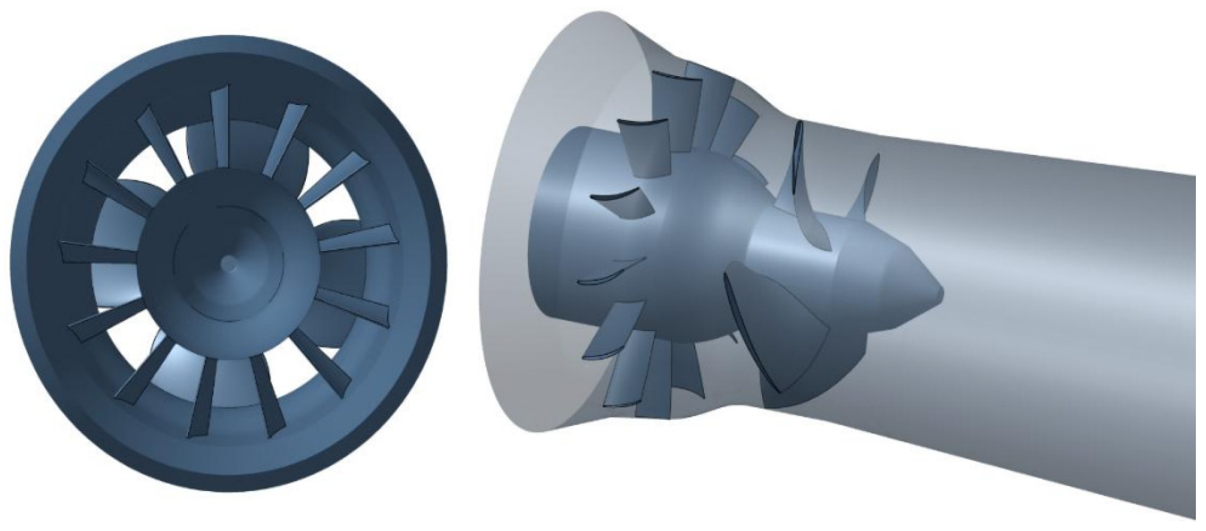
This new high-specific speed hydraulic propeller turbine for low and ultra-low heads has been developed in cooperation with the University of Genova by SEMI Industrial, which is a high-technology, mid-size Brazilian hydraulic turbine manufacturer. The previous papers have described the new turbine optimized design, starting from 1D and 2D preliminary design procedures and design criteria reported in detail in [7], which provide the initial geometry as the starting point of an organized sequence of 3D CFD advanced simulations featuring a design optimizing method aimed to obtain the targeted operating conditions with the maximum turbine hydraulic efficiency and minimum kinetic energy losses at the turbine exit section [8]. A 3D rendering of the reference turbine with fixed geometry (a single-point operating turbine) is reported in Figure 1.
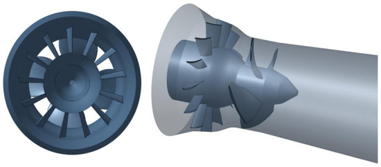
Figure 1.
A 3D rendering of the low-head axial flow hydraulic turbine of ref. [7].
The main design operating parameters of the turbine at its design operating point are reported in Table 1:

Table 1.
Propeller turbine design operating parameters.
The reported efficiency is defined as:
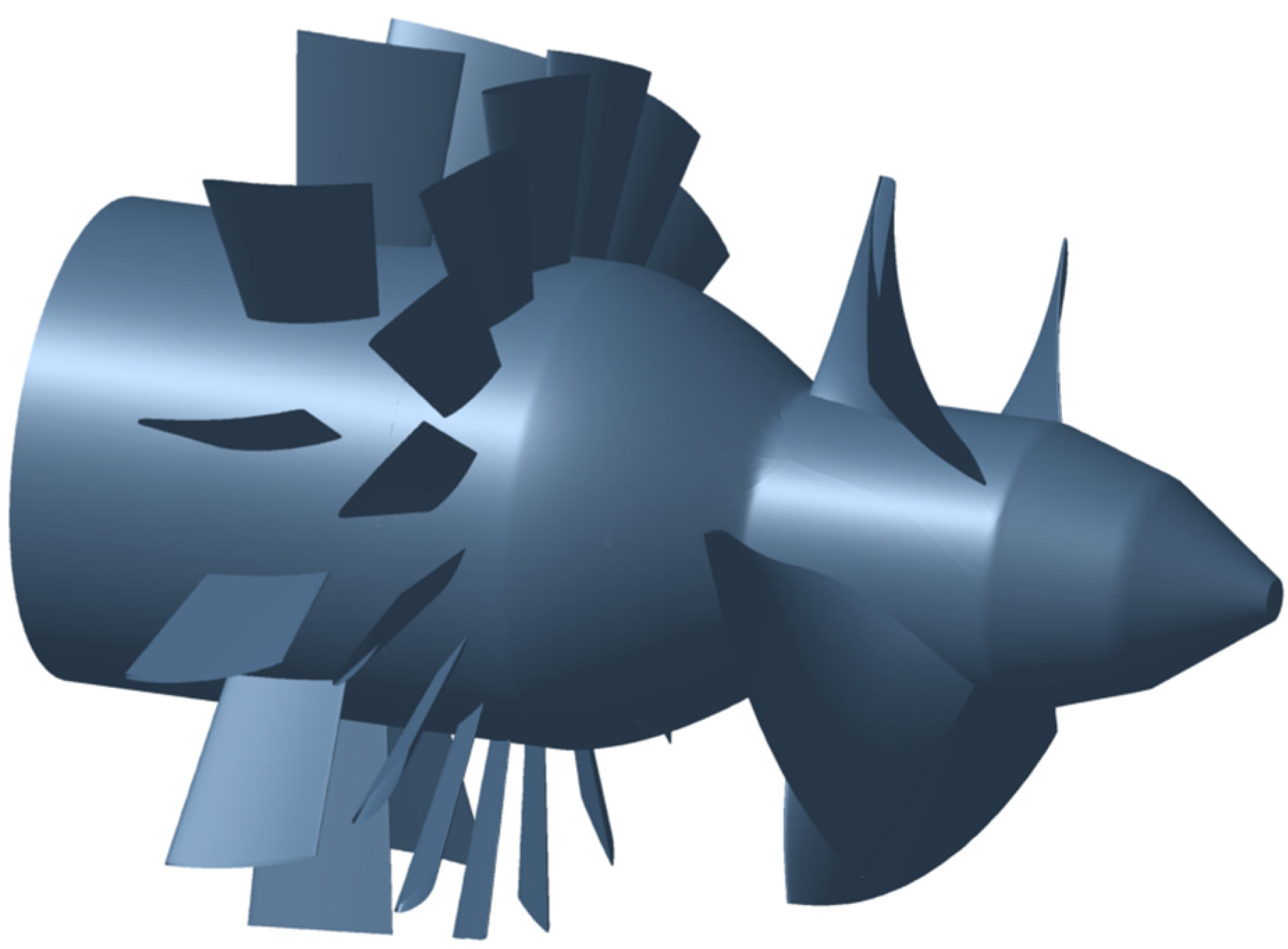
where is the torque, and is the term related to lost tangential kinetic energy at draft tube outlet. In order to make possible the turbine flow rate regulation, the above-described propeller turbine (single point operating turbine) has been modified by introducing regulating guide vanes (Figure 2) and the possibility of electronic control of the rotational speed in proportion to the flow rate variations. The shape of the meridional channel was kept unchanged, but it was necessary to axially extend the initial cylindrical part of the channel to house the two stator rows.
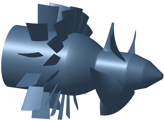
Figure 2.
A 3D rendering of the regulating low-head axial flow hydraulic turbine.
4. Turbine Meanline Design and Off-Design Analysis
Keeping the design operating point of the regulating turbine at the same conditions of the non-regulating turbine, for a rotor tip diameter the design data are: net head , flow rate and rotational speed .
The design and off-design analysis are based on the use of 1D turbomachinery equations of the balance of flow rate, energy, and moment of momentum (the Euler equation of turbomachinery for work exchange) and the turbomachinery fundamental kinematic equation, which correlates absolute and relative flow velocities in the sections upstream and downstream of the rotor at the meanline (indicated as 1 and 2, respectively).
4.1. Meanline Basic Equations
The meanline blade velocity is , with indicated in the following as for simplicity.
is the flow coefficient that will be indicated in the following as , for simplicity:
where is the axial velocity component. is the head or work coefficient in the following indicated as , for simplicity:
The Eulerian work exchanged by the turbine rotor is:
with hydraulic turbine efficiency, assumed equal to 0.9. Therefore:
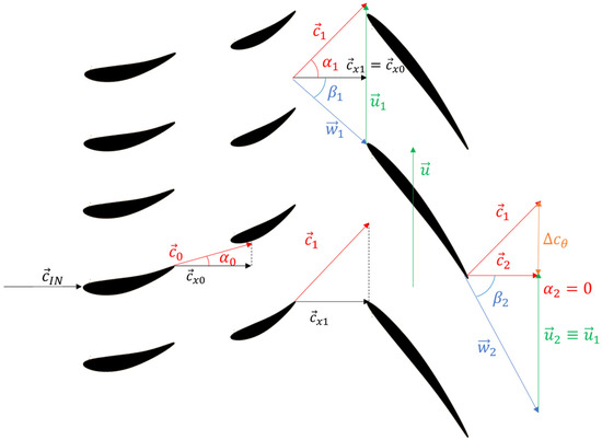
Figure 3.
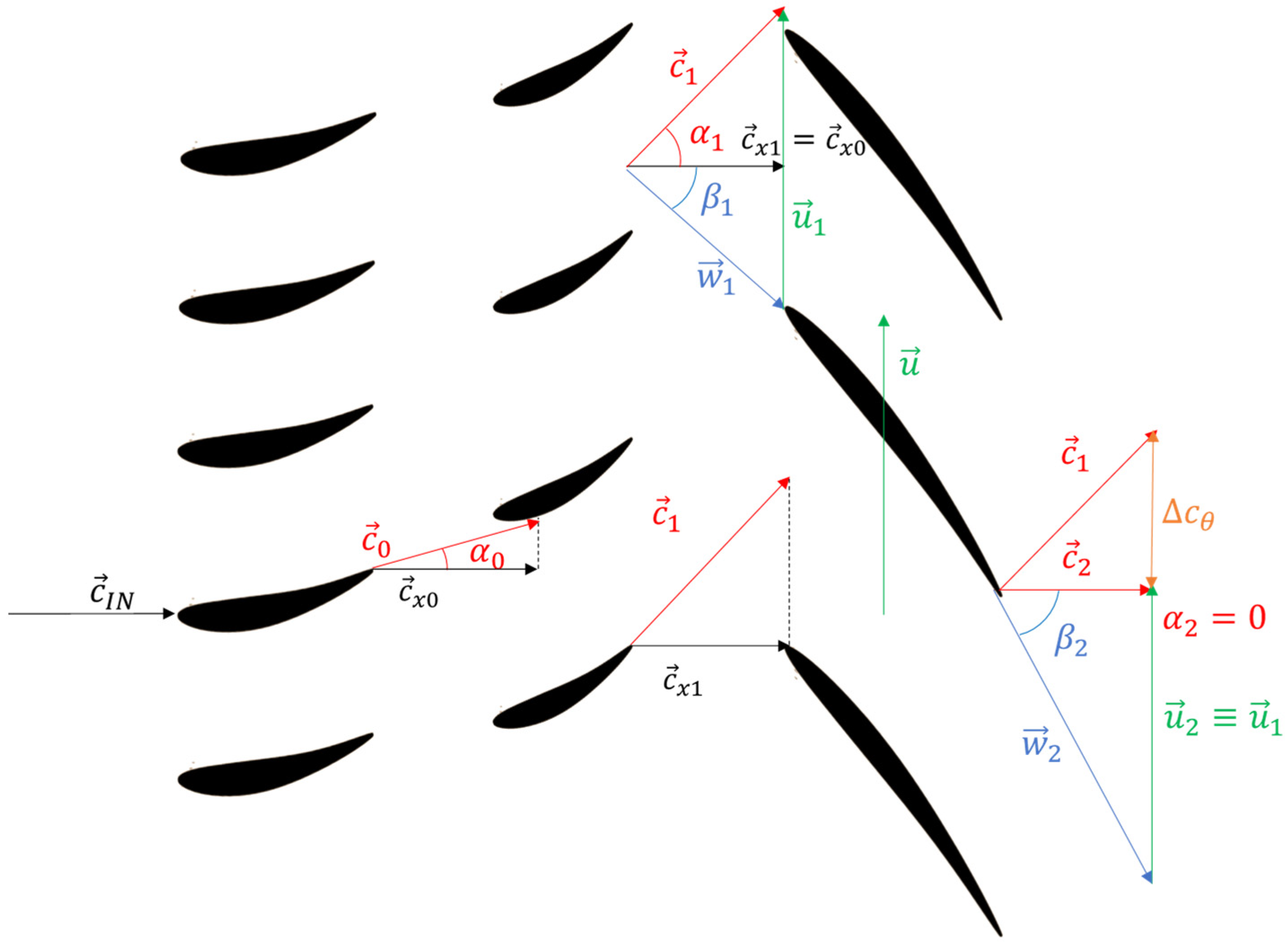
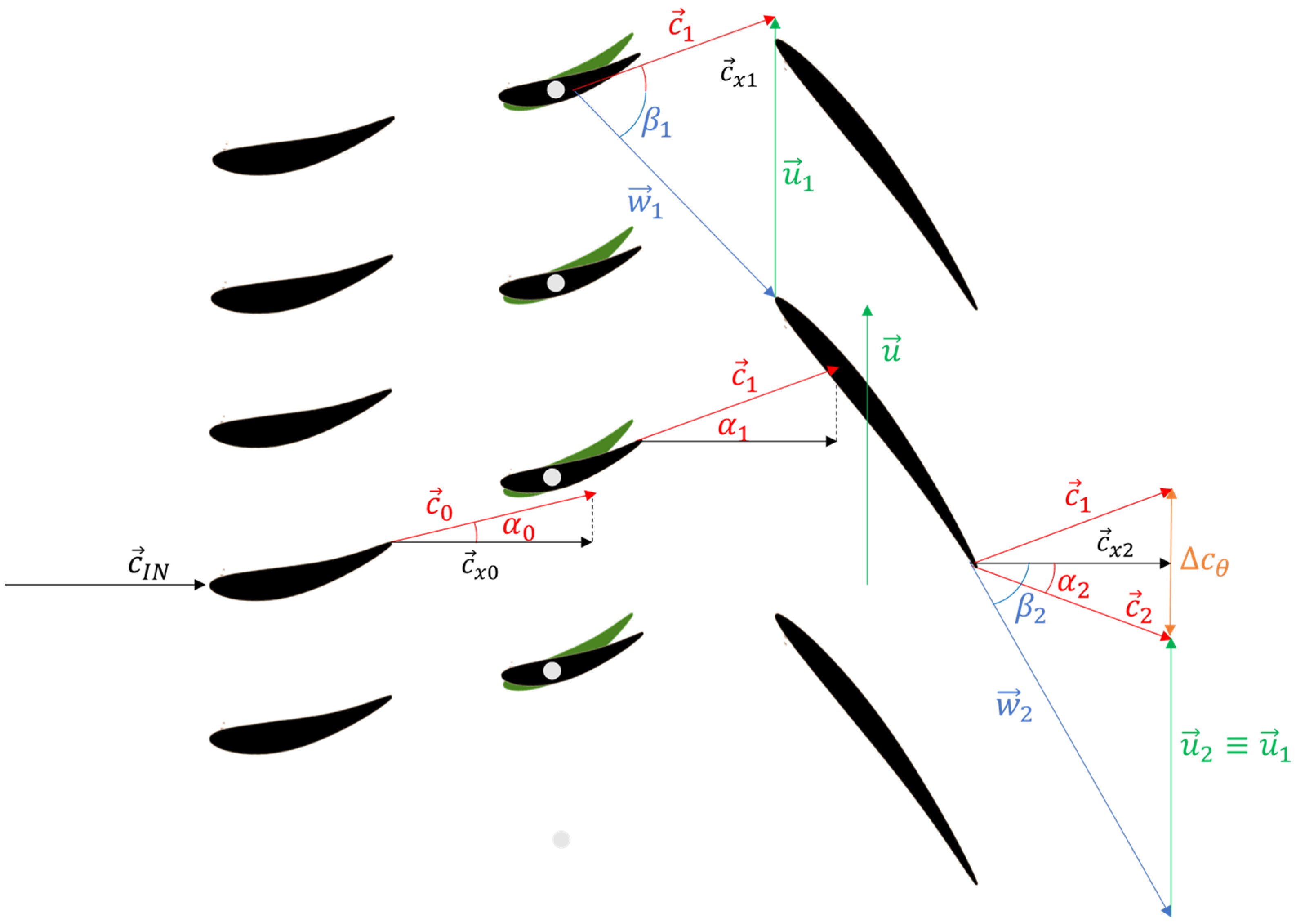
Guide vane and rotor blade profiles in the meanline blade-to-blade plane and flow velocity triangles at the design condition.
Additionally:
4.2. Design Meanline Analysis
At the design condition, the axial velocity, evaluated with the continuity equation from the design flow rate, is and it is constant from the inlet to the exit of the rotor blade. At the design conditions:
Furthermore, at the design condition, the tangential absolute velocity is imposed null to minimize the kinetic energy loss at the turbine exit and then . By applying in sequence Equations (11), (12), and (14), we obtain:
For meanline simplified and off-design analyses, we assume that the rotor blade profile angles coincide with the flow angles at the design conditions: and , that corresponds to the assumption that the exit flow deviation angle is null and the incidence angle is null at the design condition. Figure 3 shows the vane and blade profiles and the velocity triangles at the design condition in the meanline blade to blade plane.
4.3. Off-Design Meanline Analysis
The off-design meanline conditions at the constant net head are represented by the reduction or increase of flow rate operated by the guide vane opening angle variation. For simplicity, we assume that , with . Therefore, since is proportional to , , for simplicity denoted as
If we assume that the rotational speed and, therefore, the blade velocity can be varied respect to the design condition, we can write , for simplicity denoted as
As a consequence for simplicity (Equation (15)) and , for simplicity (Equation (16)).
For , the rotational speed is not varied with respect to the design condition; this condition represents the simple guide vane regulation. If = , a strict proportionality between the axial velocity component and blade velocity is established via the frequency electronic regulator that completely suppresses the tangential velocity component at the rotor exit induced by the off-design conditions in case of constant rotational speed , but unfortunately enhances incidence angle variation at the rotor blade inlet. An intermediate regulation strategy with , is also considered.
Furthermore, for the off-design meanline analysis, we assume that and .
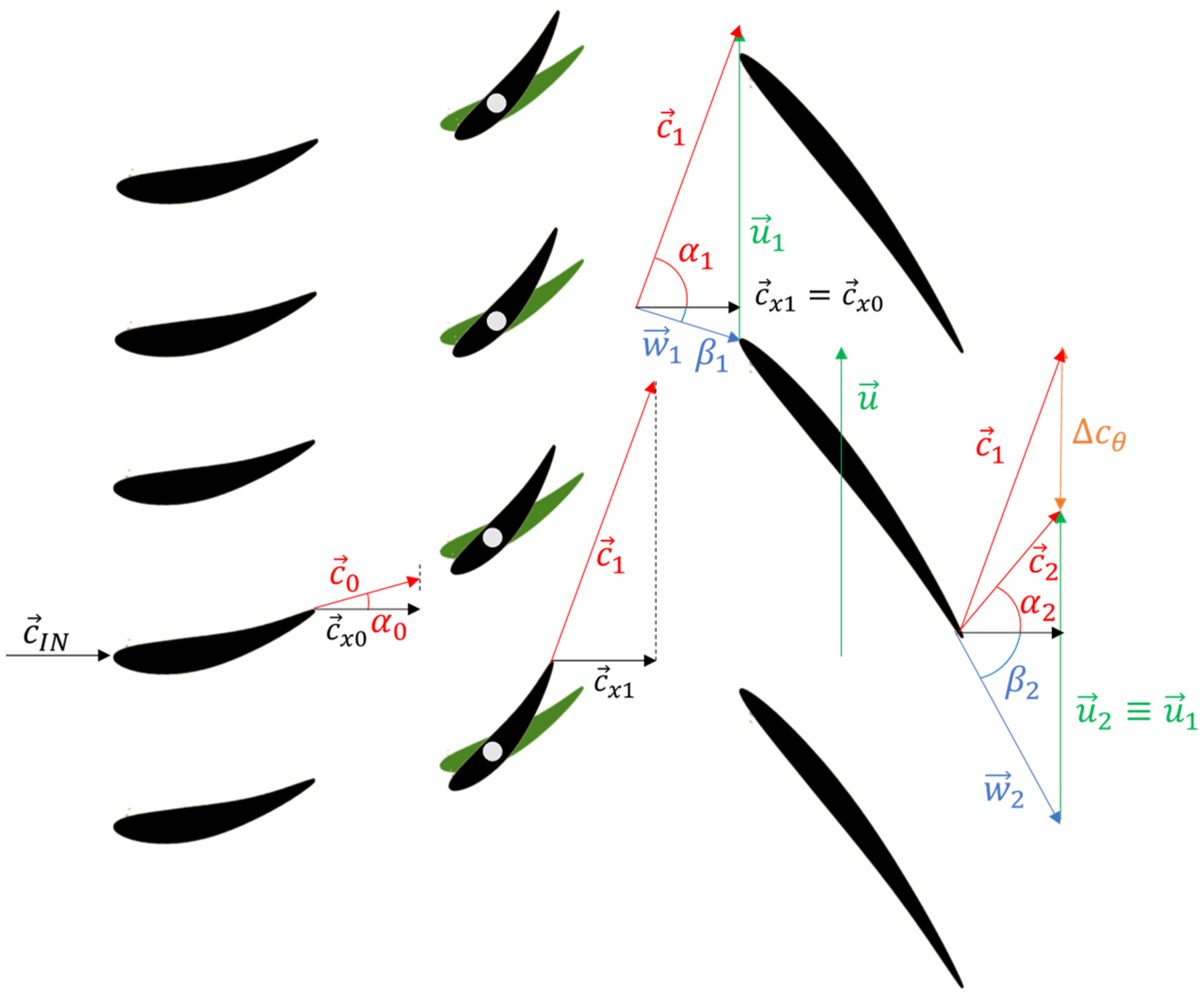
From the analysis of Figure 4 and Figure 5, one important feature is evident. Operating under the constant net head, if the power regulation is performed only by the guide vane opening variation, a reduction in flow rate (Figure 5) induces a significant co-rotating tangential velocity component at the blade exit, and an increase in flow rate induces a counter-rotating tangential component. Both positive and negative tangential velocity components may cause important energy conversion losses.
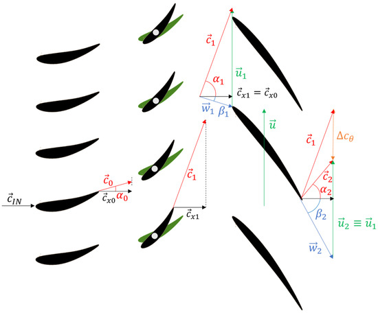
Figure 4.
Guide vane and rotor blade profiles in the meanline blade-to-blade plane and flow velocity triangles at off-design conditions (, simple guide vane regulation)—flow rate reduced.
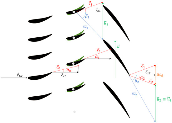
Figure 5.
Guide vane and rotor blade profiles in the meanline blade-to-blade plane and flow velocity triangles at off-design conditions (, simple guide vane regulation)—flow rate increased.
As a second consequence, at nominally constant work conversion, the residual tangential velocities at the exit need to be compensated by an increase of the tangential velocity component at the rotor inlet in the case of co-rotating exit swirl and a decrease of the inlet tangential velocity in the case of counter-rotating exit swirl, and this needs to be obtained by overclosing and overopening the guide vanes.
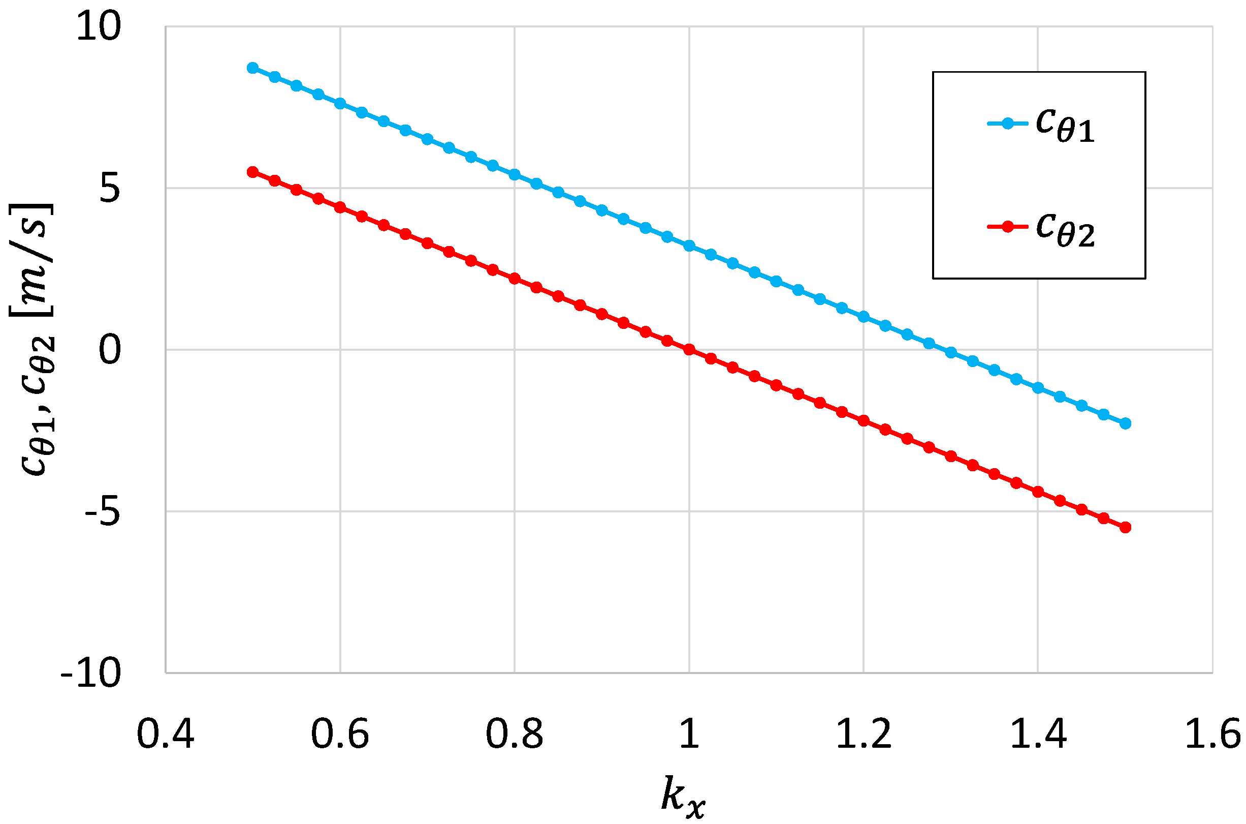
This concept is clearly shown in Figure 6, which reports the flow tangential velocity components at the rotor inlet and exit. It is worth observing that, when operating at constant net head, the simplifying assumption of constant hydraulic efficiency in Equation (3) (Eulerian work exchanged by the turbine rotor) imposes a constant tangential velocity variation all over the flow rate range.
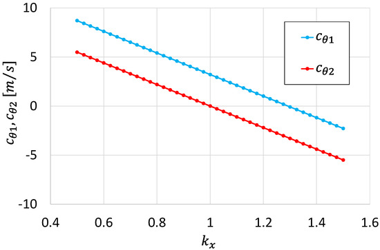
Figure 6.
Tangential velocity components , . Case (simple guide vane regulation).
One further observation about Figure 6 is that the practical impossibility of applying a vane stagger angle larger than 90° (respecting the tangential direction) imposes a direct limitation to the operating range at a large flow rate, which in the present case is 130/100 of the design operating point.
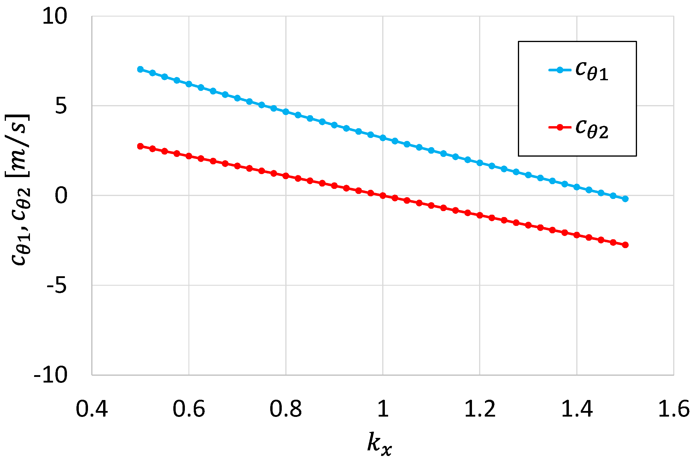
Figure 7 shows the positive effect of the rotational speed variation, = (1 +, in reducing the amplitude of the residual tangential velocity components at the rotor exit, . This also results in a consequent reduction of the amplitude of the inlet tangential velocity component, , which is necessary to provide the rotor work exchange compatible with the available net head. Therefore, the rotor inlet absolute flow angle is reduced, with a positive consequent reduction of the vane opening variation with respect to the design vane opening condition. The operating range at large flow rate is increased, as a consequence, towards 150/100 of the design operating point.
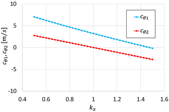
Figure 7.
Tangential velocity components , . Case , (combined guide vane and rotational speed regulation).
4.4. Off-Design Losses
Off-design losses are the losses that originate at off-design conditions. They are, traditionally, rotor blade incidence losses and kinetic energy losses associated with the tangential velocity at the rotor exit . At the design condition, in fact, the incidence angle is and .
Several incidence loss correlations are available in the literature; for instance, the Galvas correlation [17], which can be utilized for its simplicity. However, for the present analysis, we have decided to use the most classical correlation for axial turbines profile losses; the Ainley–Mathieson correlation [18], also employed in more sophisticated loss models, such as the one proposed by Dunam–Came [19], and successively by the one proposed by Kacker–Okapuu [14].
In the present paper, profile losses are defined as lost head in percentage of the net head as:
where
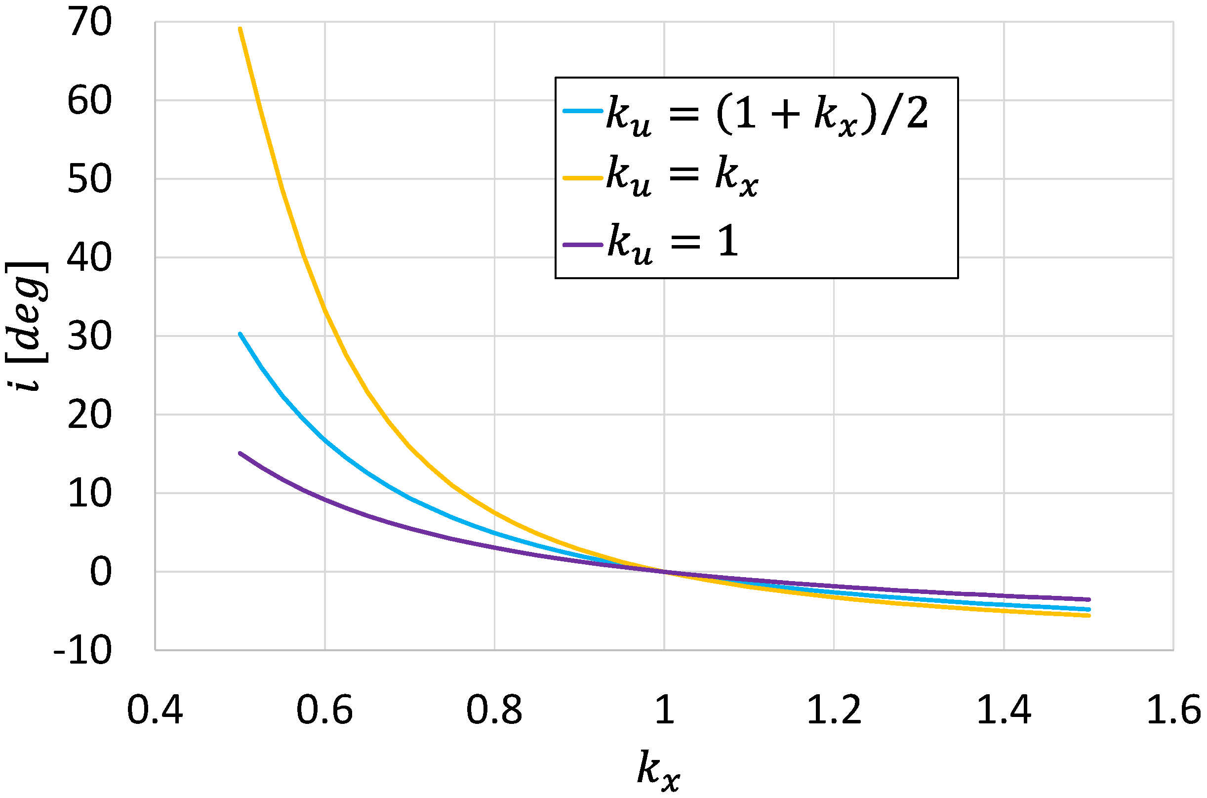
is the Ainley–Mathieson profile loss coefficient at design condition, evaluated as 0.03 from Figure 4 of the Ainley–Mathieson paper, and is the incidence angle coefficient calculated with a grade 6 polynomial fitting the curve of Figure 6 of the same paper. Figure 8 shows the trends of the angles of incidence deduced from the 1D meanline analysis for the various regulation strategies.
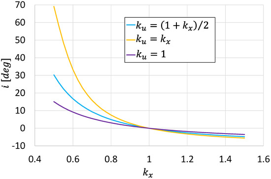
Figure 8.
Incidence angle overflow rate range. Cases , , .
It is interesting to note how the values of the incidence angle are of limited entity and negative for values of greater than unity. On the contrary, for low values of , the incidence angle shows a strong increase, mostly for .
The off-design kinetic energy loss can be simply evaluated by its definition as:
where:
Additionally, is the exit rotor blade angle and in case of regulation without blade angle opening variation as in the present case it coincides with the design exit relative flow angle and is the turbine efficiency at design point. Now:
Therefore, the off-design kinetic energy losses can be written in compact form as:
Therefore, in case we assume the off-design kinetic energy losses due to residual tangential velocity at the rotor exit are null by definition. However, the effect of over the incidence angle, at reduced flow rate conditions, is strong and may increase the profile losses excessively.
In the present simplified concept analysis, for the sake of simplicity and due to the inherent limitations of the meanline model, the evaluation of the quality of the different regulation strategies is based only on the level of the sum of the profile losses and tangential kinetic energy losses that will be indicated as “rotor overall meanline losses”. The simplified analysis cannot consider other significant turbine losses, namely distribution losses, rotor secondary losses, and mixing losses, which, on the contrary, are inherently taken into consideration in the 3D CFD analysis that will follow in the next paragraph.
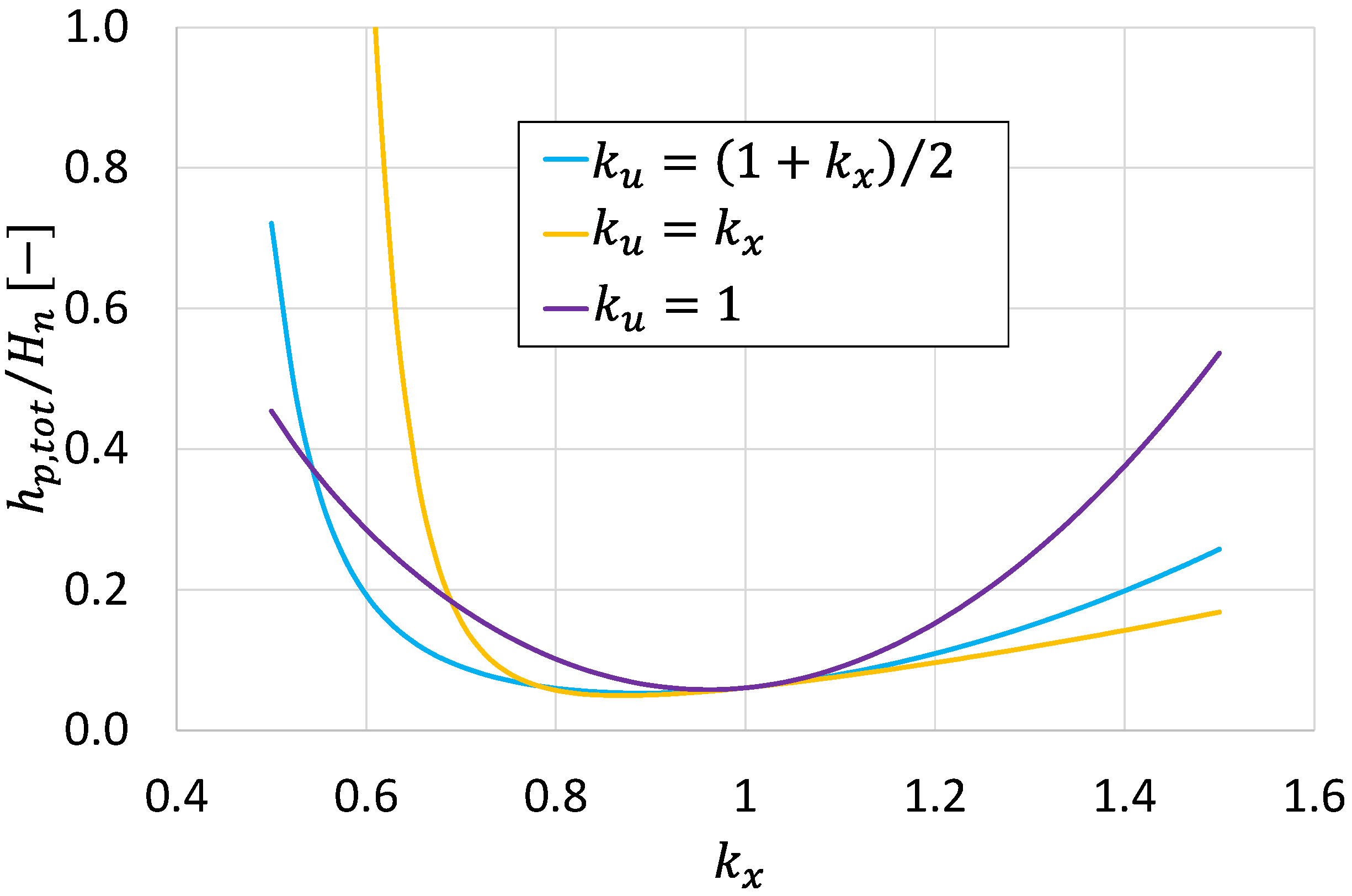
Figure 9 reports the distribution of the overall meanline rotor losses normalized with the available net specific energy to be converted (net head ) over the turbine flow rate range for the 3 examined cases (, , ). The loss distribution analysis clearly indicates that a combined regulation strategy based on a different law of variable rotational speed (namely for and for ) reduces significantly the rotor overall losses respect to the case with simple guide vane regulation () and extends the range where the losses are lower than 20% from to .
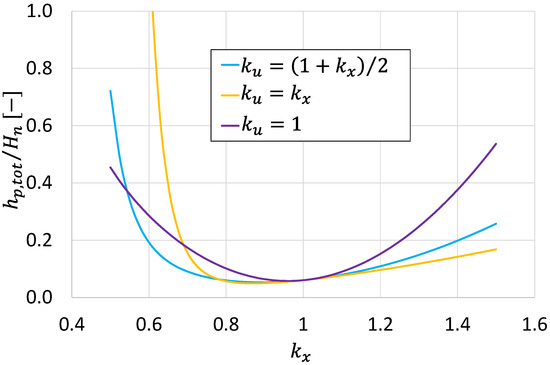
Figure 9.
Normalized rotor overall meanline loss distributions overflow rate range. Cases , , .
5. Turbine 3D CFD Simulation
In order to overcome the inherent limitations and approximations of the 1D meanline approach in evaluating and validating the new flow rate regulation concept, a fully 3D CFD simulation procedure based on the RANS approach has been applied for the complete off-design analysis of the turbine operating with the 3 different regulating conditions (, , ).
The turbine 3D steady state RANS analysis has been carried out utilizing the Cadence CFD software [20], which is widely used in turbomachinery applications.
Similarly to the 3D turbine design analyses reported in [7,8], the definition of the turbine geometry was carried out through the generation of a file defining the geometry of the turbine meridional channel and the coordinates of the three blade rows constituting the turbine (stay vanes, guide vanes, and rotor). However, differently from the above references, since in the present study different operating conditions and thus different distributor geometries need to be simulated, the shape of the guide vane row was managed by means of a simple calculation software capable of providing the position of the points that define the guide vane row once the correct stagger angle was defined and imposed by the operating condition of the turbine.
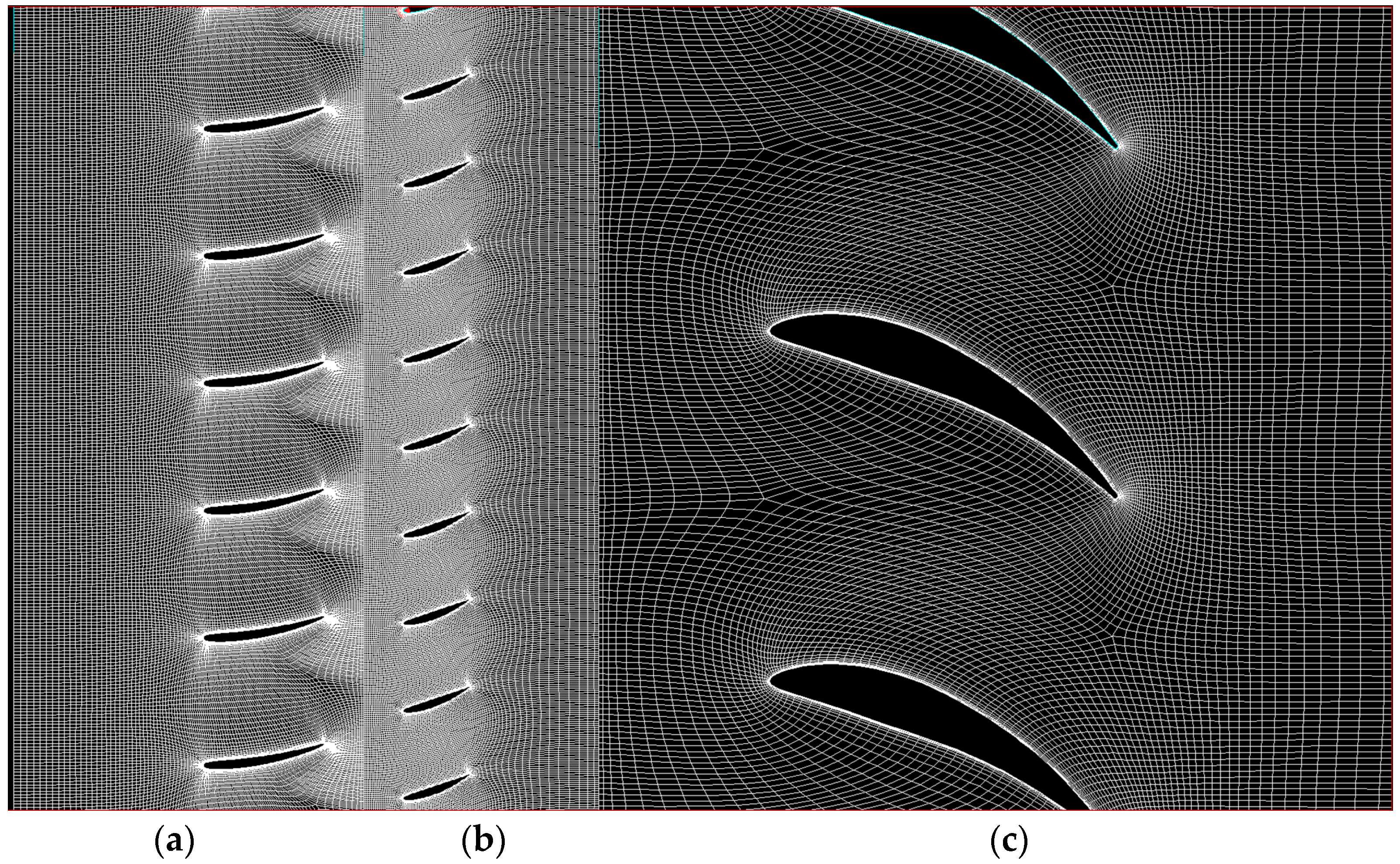
The computational mesh was prepared in Autogrid 5 by Cadence and consists of about 5 million nodes. A multi-block approach with O-4-H mesh topology for stay vane, guide vane, and rotor rows was adopted (Figure 10), while for the downstream axial draft tube, a suitable mesh capable of managing the condition of singularity on the axis was employed. A single blade passage per row has been simulated, and the passage of information from the stator frame to the rotor frame is managed by a mixing plane approach.
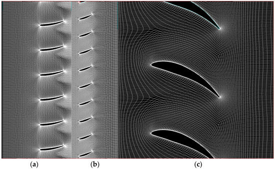
Figure 10.
Blade-to-blade mesh for stay vanes (a), guide vanes (b), and rotor blades (c).
Grid independency was checked by employing three different mesh densities for the nominal configuration case and evaluating the two main operating parameters of the turbine, i.e., the net head and the turbine hydraulic efficiency . The results of the analysis are presented in Table 2.

Table 2.
Grid dependency results.
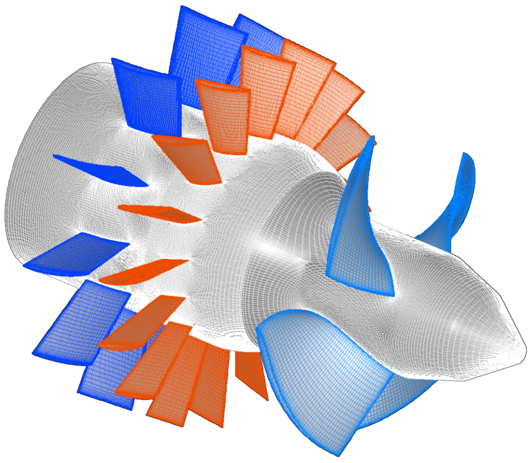
The intermediate grid configuration (Grid 2) is used for all the simulations presented below since it presents overall values comparable with those of the finer grid (Grid 3). Figure 11 shows the surface mesh configuration.
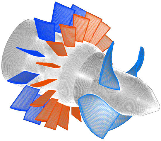
Figure 11.
Turbine surface mesh configuration.
The discretization of the equations in space is based on a cell-centered control volume approach, while a multistage Runge–Kutta scheme with local time stepping is adopted for time discretization and is associated with the multigrid technique [20].
For turbulence modeling, the one equation Spalart–Allmaras [21] model is employed, which has been proven capable of providing a simple yet reliable turbulence effects evaluation in hydraulic applications [22,23,24]. The height of the first cell near the solid walls is chosen for each row so that the value of the non-dimensional wall coordinate y+ is around 1.
As boundary conditions at the inlet section, the mass flow rate, static temperature, and flow direction are assigned, while at the outlet section, the averaged static pressure due to the hydrostatic head at the exit is specified. A turbulent viscosity boundary condition at the inlet has been imposed starting from turbulence intensity and characteristic length scale values, assumed to be 3% and the rotor blade chord, respectively, by means of classic formulae [20].
Since the solver employs a density-based approach, the Hakimi [25] preconditioning model is adopted for treating the incompressible flow condition.
The different operating conditions were simulated in sequence. The simulation process consists of a series of steps:
- The guide vane stagger angle and the rotational speed, related to a selected operating condition, are imposed;
- The calculation proceeds until convergence is reached. The value of total pressure drop across the machine is employed to evaluate the net head value;
- If the obtained net head is different from the one chosen for the actual application () the inlet mass flow rate is adjusted: in particular, if the obtained net head is lower than the design value, the inlet mass flow rate is increased, while if the obtained net head is higher than design value, the inlet mass flow rate is reduced;
- The process is repeated iteratively until obtaining the value of the net head equal to the value chosen for the actual operating condition.
6. Off-Design CFD Simulation Results
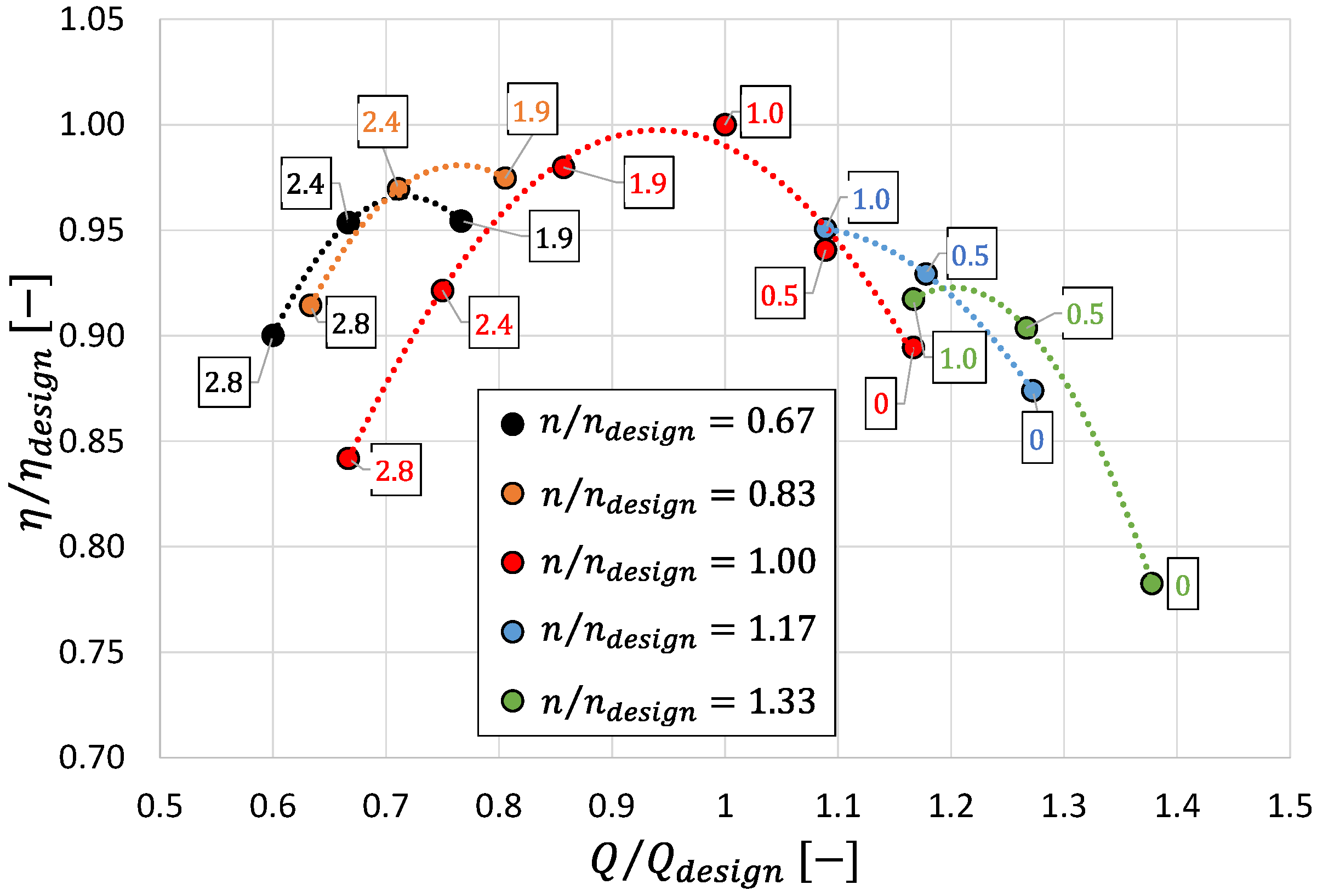
Results from the extensive off-design 3D CFD simulation of the low-head turbine prototype are shown in Figure 12 and Figure 13. The results are given for the case of simple guide vane regulation of the flow rate under a fixed head and for the case of the new regulation approach based on the conjugate variation of the guide vane opening and turbine rotational speed.
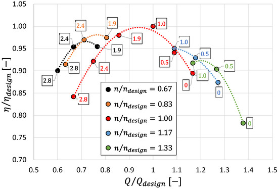
Figure 12.
Normalized efficiency curves versus the fraction of the design flow rate under the constant design net head. Numbers in the squares represent the ratio between actual and design guide vane stagger angles.
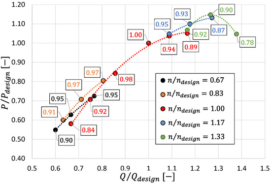
Figure 13.
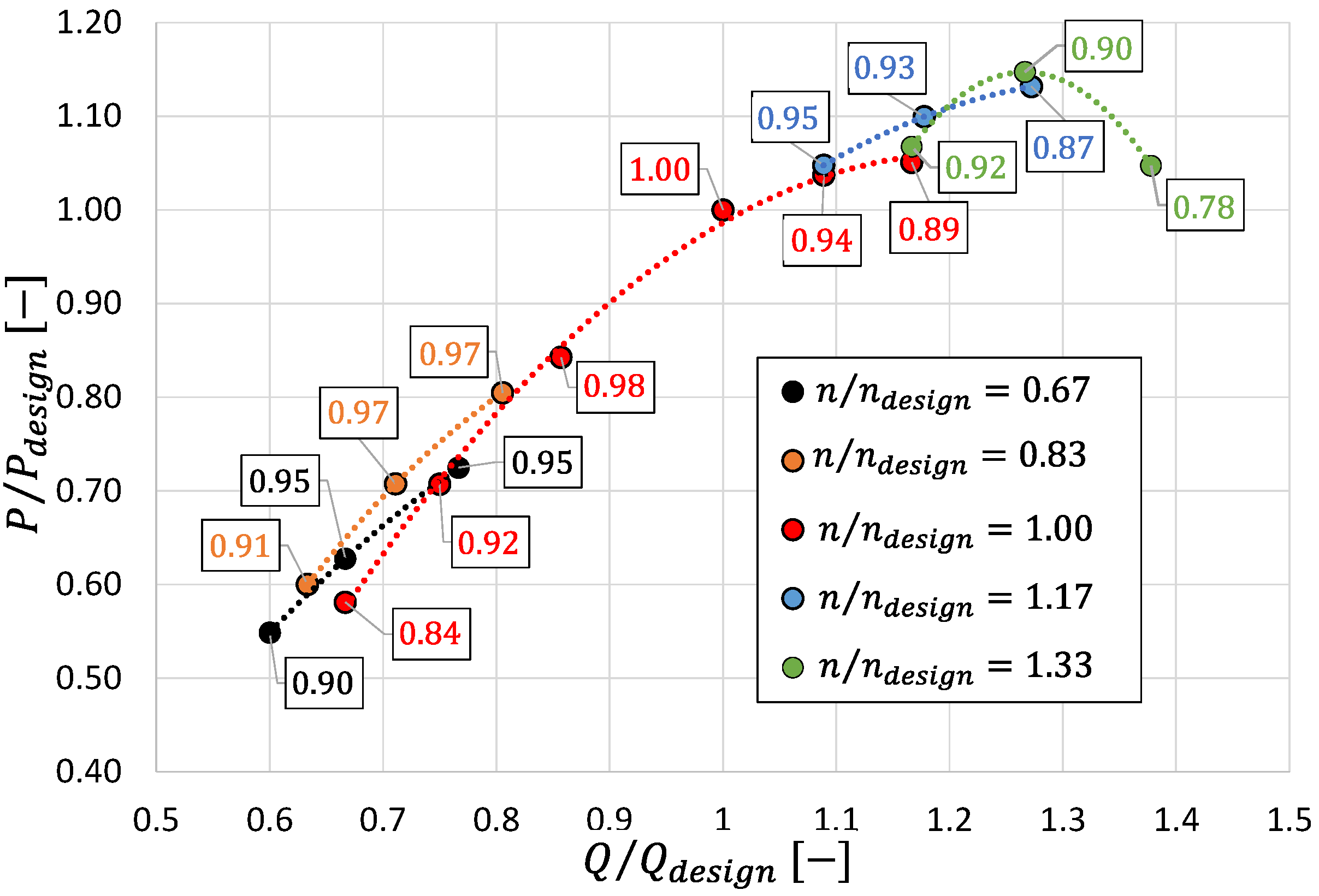
Normalized power curves versus the fraction of the design flow rate under the constant design net head. Numbers in the squares represent the normalized turbine hydraulic efficiency in agreement with Figure 12.
Figure 12 reports the normalized efficiency curves in function of the fraction of flow rate with respect to the design flow rate under constant design net head. Nominal rotational speed corresponds to the red line, while the number indicated in the squares represent the ratio between actual and nominal guide vane stagger angles. It should be noted that the quantities and correspond, respectively, to the parameters and , used in the 1D analysis.
The validity of the combined regulation in enlarging the flow rate operation range, already inferred from 1D results, is confirmed by the 3D CFD RANS results.
However, it is worth to observe that the control strategy deduced from the 1D theory is only partially correct. In fact, observing, for example, the condition , the maximum efficiency is obtained in the case with (and therefore , black curve), contrary to what was obtained from the preliminary 1D calculation. Therefore, contrary to the 1D meanline analysis with loss evaluation based only on rotor profile loss correlation, for the fully 3D CFD RANS analysis the best strategy is (or and also for the reduced flow rate .
Figure 13 shows the power curves, normalized with respect to the design power value, for the different flow rate values and for the different rotation speeds. In this case, the numbers in the rectangles indicate the corresponding efficiency value normalized with respect to the design condition, according to the curves of Figure 12.
Figure 13 indicates that the proposed flow rate regulation concept, thanks to the increase of the efficiency respect to the single regulation, allows to increase the turbine output power respect to the single guide vane regulation approach in the operating ranges with below 0.80 and above 1.10.
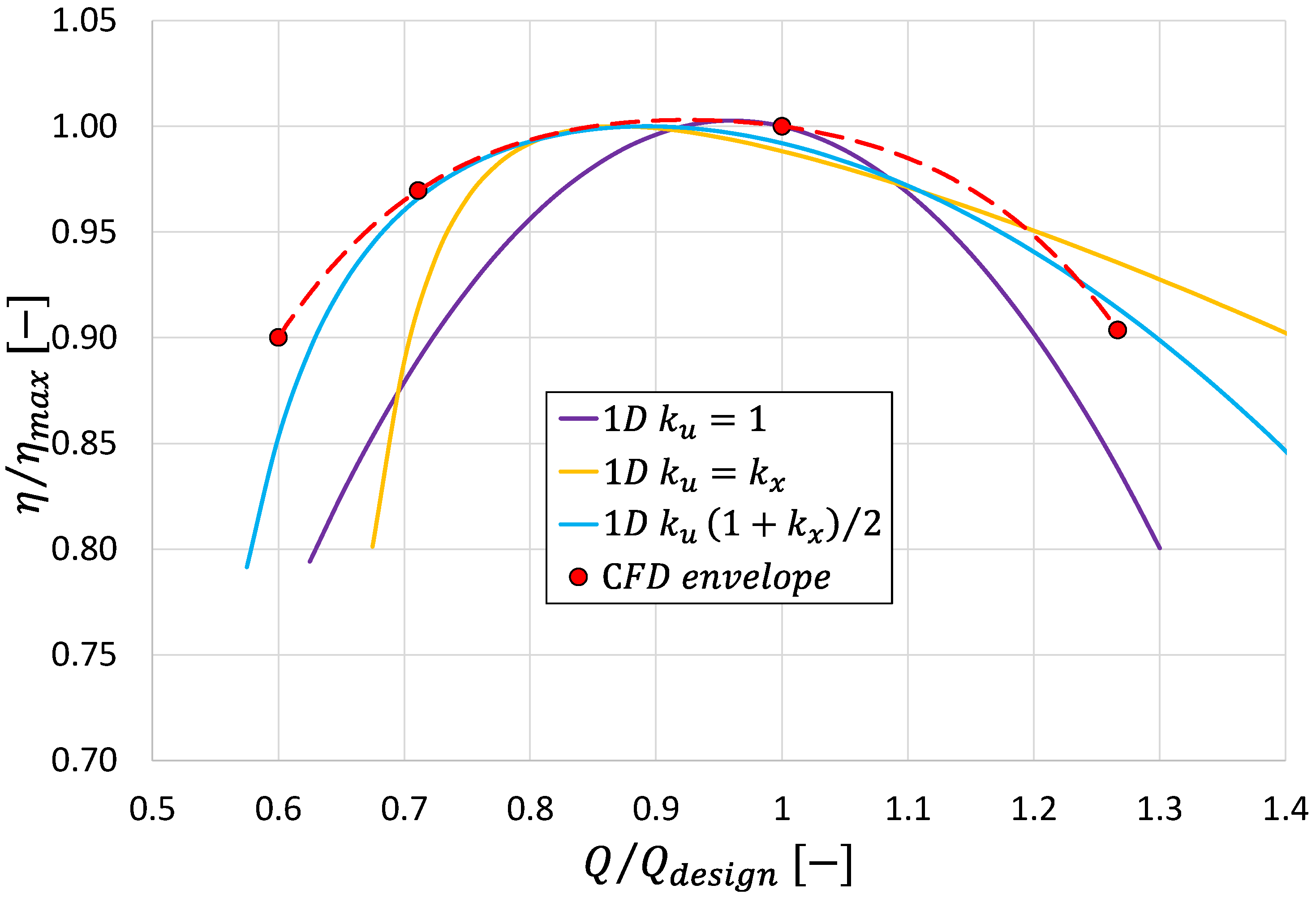
To highlight the positive effect of the combined control strategy in terms of enlargement of the turbine operating range with acceptable hydraulic efficiency levels, the envelop curve of the points with the highest efficiencies obtained from the CFD calculation has been evaluated and shown in Figure 14. Comparing the efficiency envelop curve of Figure 14 and the efficiency curve of Figure 12 for (single guide vane regulation), the flow rate range of acceptable off-design operation, assumed as the range where the hydraulic efficiency remains above or equal to 0.9 of the design efficiency, has been clearly enlarged from to
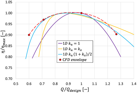
Figure 14.
Normalized efficiency curves versus the fraction of the design flow rate under the constant design net head: the 1D theory results compared with the CFD envelope curve.
In order to provide a qualitative comparison between the results of the 1D theory, albeit with its limitations, and those of the CFD calculation, Figure 14 also shows the normalized efficiency curves from the 1D theory, obtained as a complement to 1 of the losses shown in Figure 9.
However, it should be emphasized once more that, apart from the residual tangential kinetic energy evaluation that is similar for the two approaches, the loss evaluation procedures for 1D theory and CFD 3D analysis are intrinsically different, and the results cannot be directly compared. The 1D theory loss evaluation considered is based only on rotor profile loss correlations, and it is useful mainly to understand and explain the concept, while the 3D CFD analysis takes into consideration all the loss mechanisms that occur between the inlet and outlet sections of the turbine, and, therefore, only the efficiency envelope curve of the 3D CFD analysis can be considered a reliable approximation for evaluating the regulation strategy.
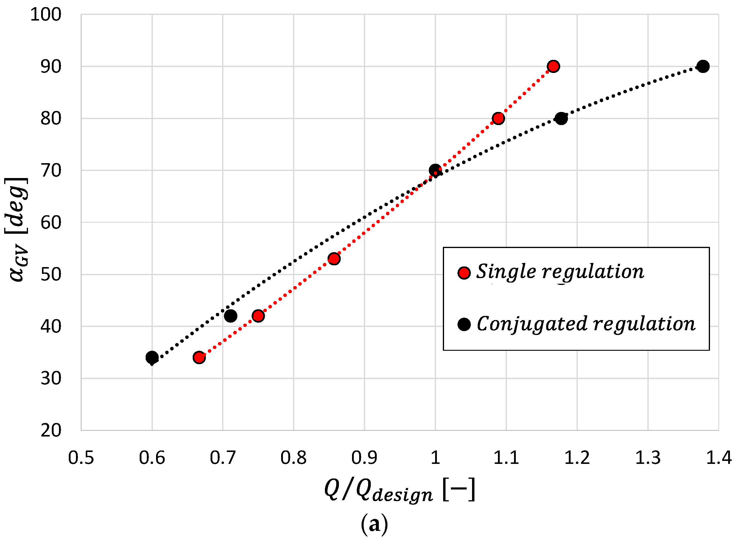
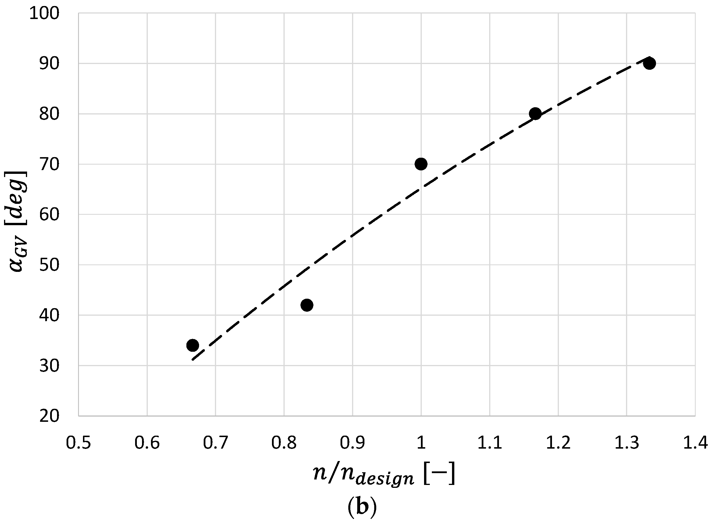
As a further analysis step of the CFD results, Figure 15a shows the guide vane opening angle laws as a function of the fraction of the design flow rate for the case with only guide vane regulation and for the case with combined guide vane opening angle and rotational speed variation, having considered, for this latter case, the points corresponding to the efficiency envelope curve. An important advantage of the combined control strategy is the significant reduction, especially at large flow rates, of the guide vane opening angle variation required to obtain the desired flow rate variation with respect to the single guide vane regulation. Figure 15b reports, as the final step of this analysis of the CFD results, the conjugation curve of the two regulation parameters, i.e., the guide vane opening in function of the rotational speed variation, that allows the flow rate variation with the optimum efficiency conditions.
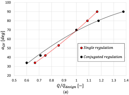
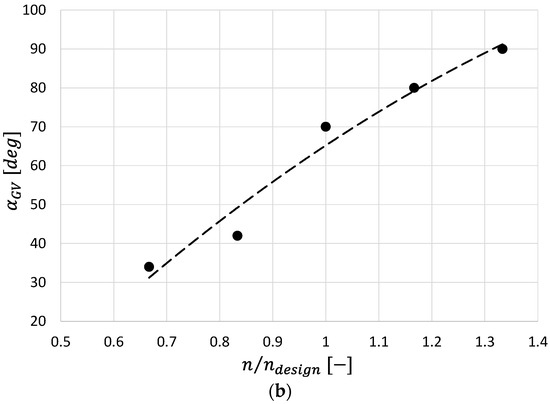
Figure 15.
Guide vane opening angle law as a function of (a), and the conjugation curve (b).
To better compare the effects of the different loss contributions, two loss parameters, related to the generation of entropy and to the residual tangential kinetic energy at the exit of the rotor row, are defined:
where is the entropy local variation with respect to the turbine inlet section value;
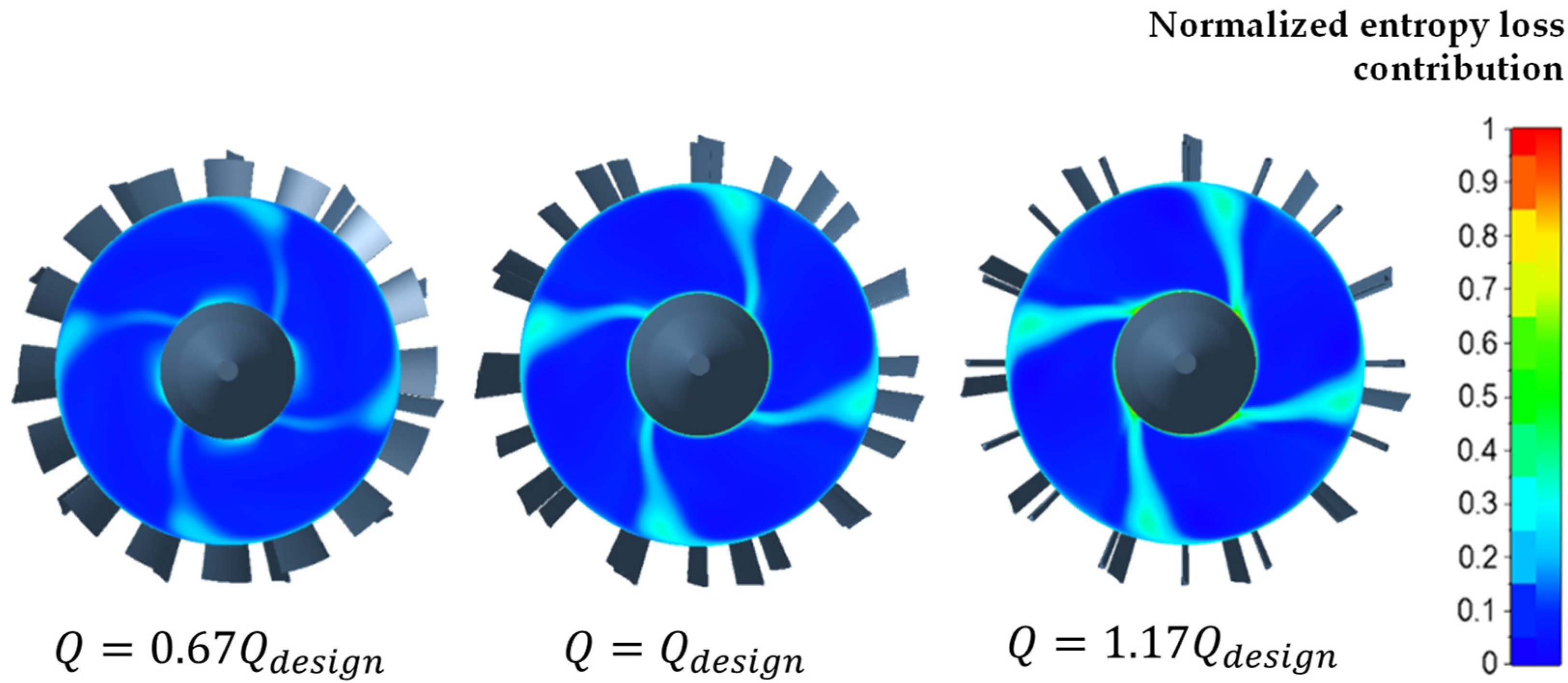
This latter contribution, although defined in a similar way to Equation (19), differs from that since it is calculated from the local value of the tangential velocity component obtained from the CFD calculation. Figure 16 shows the maps of the normalized entropy loss contribution for three different flow rates at a nominal rotational speed. The operating condition variation generates rather moderate variations in the maps with an expected clear tendency of increasing the entropy loss parameter as the flow rate increases.
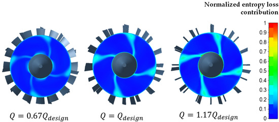
Figure 16.
Normalized entropy loss contribution at a design rotational speed for three different flow rates at design rotational speed—.
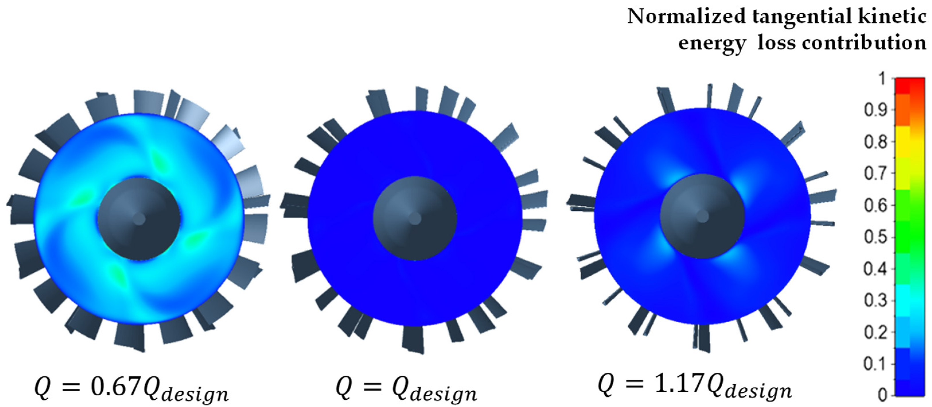
Figure 17 shows the normalized tangential kinetic energy contribution for the same three operating conditions previously reported. This contribution shows an increase if the flow rate differs from the design value, for which this contribution is everywhere close to zero.
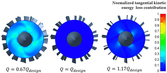
Figure 17.
Normalized tangential kinetic loss contribution at a design rotational speed for three different flow rates at design rotational speed—.
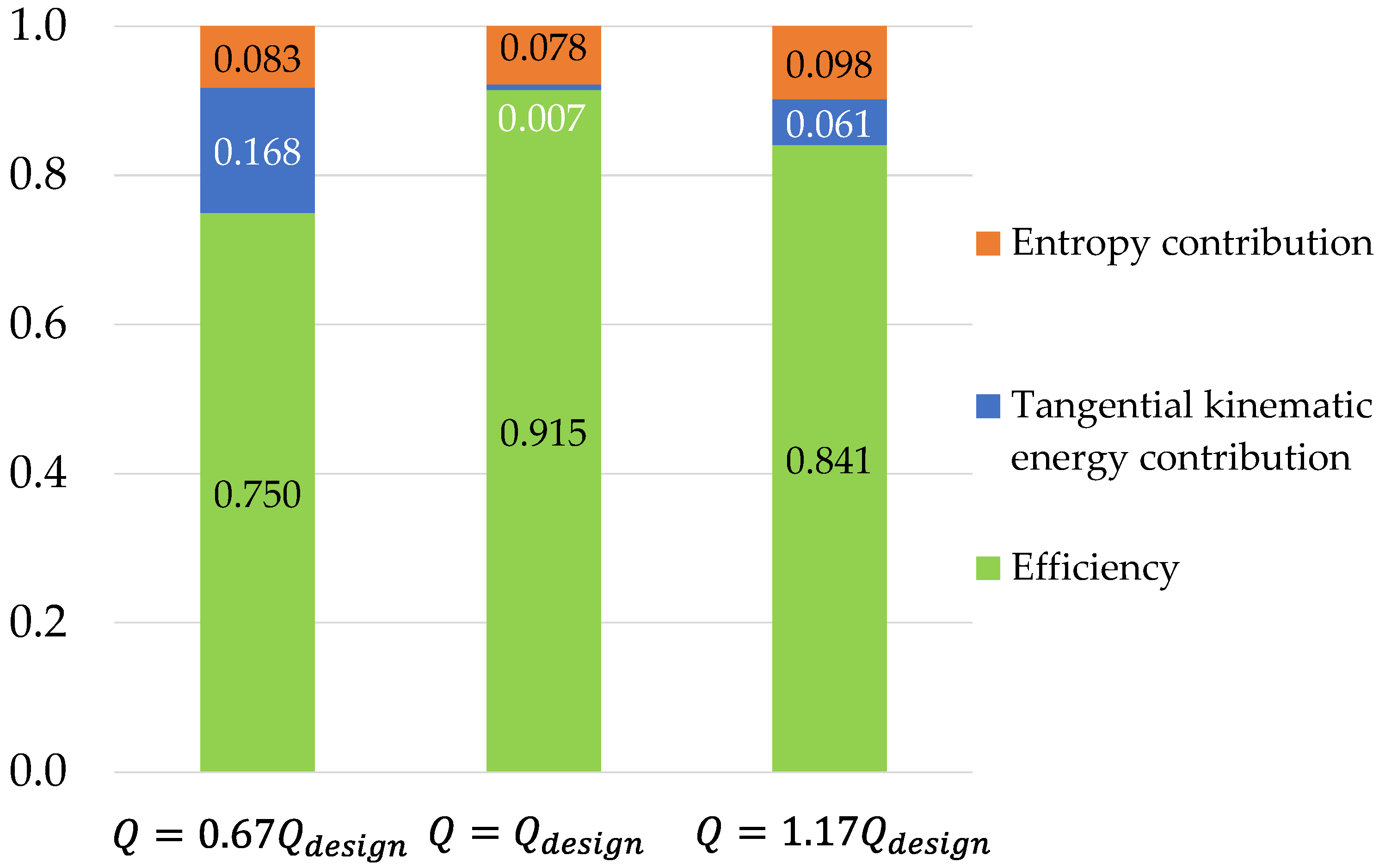
By calculating the global values of these contributions, obtained through the mass weighted average of local values, it is possible to obtain the histograms presented in Figure 18, where the efficiency also appears as a complement to 1 of the 2 main loss contributions. The diagrams make clear how the variation of the flow rate from the design conditions involves limited variations in the normalized entropy loss contribution and significant variations in the normalized tangential kinetic energy loss contribution.
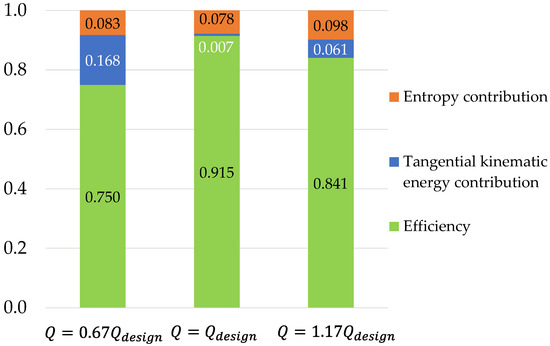
Figure 18.
Comparison of main loss contributions and efficiency for three different flow rates at design rotational speed—.
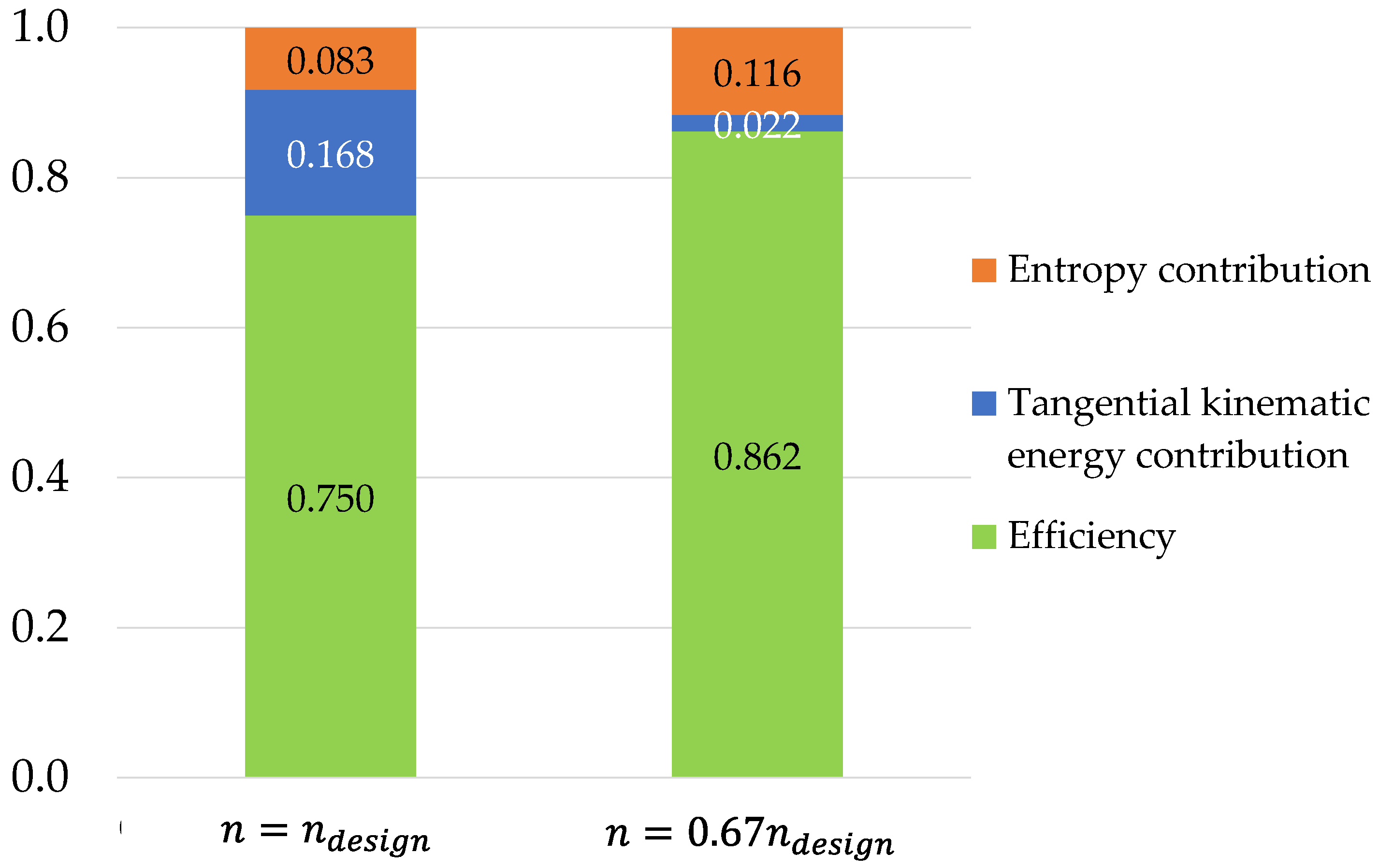
To highlight how the loss contributions change by implementing the combined regulation of guide vane stagger angle and rotation speed, Figure 19 shows the comparison of loss contributions and efficiency for 2 operating conditions at reduced flow rate , but different rotational speeds.
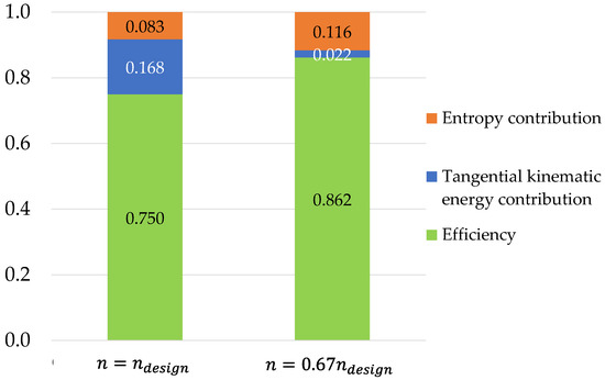
Figure 19.
Comparison of main loss contributions and efficiency at for two different rotational speeds—.
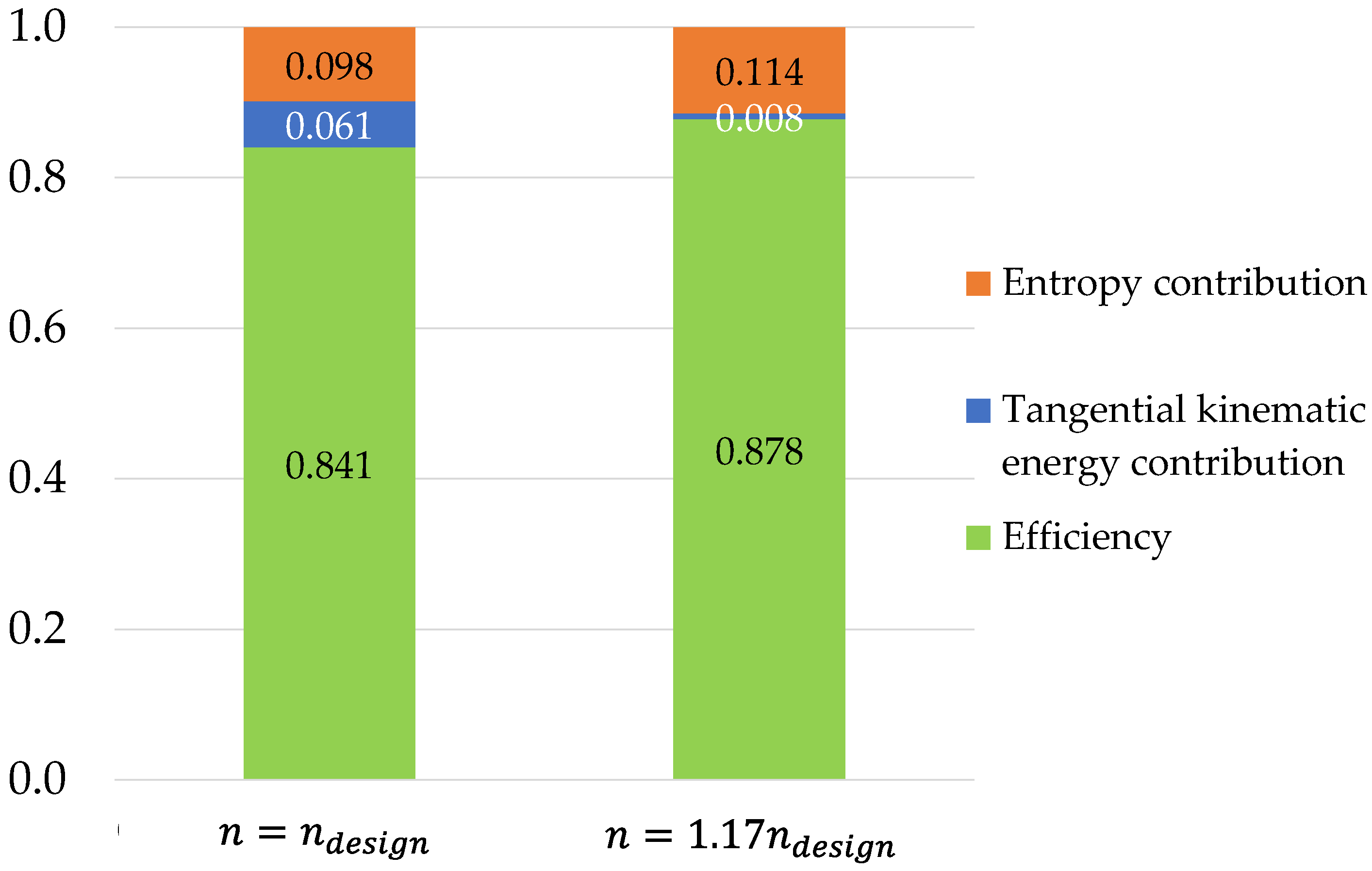
The reduction of the rotation speed leads to a considerable decrease in the normalized tangential kinetic energy loss contribution, which corresponds to an increase in efficiency, although the entropy contribution to losses increases.
Similarly, Figure 20 shows the comparison of loss contributions and efficiency for two different rotational speeds at . Additionally, at this flow rate, the proper variation (in this case the increase) of the rotation speed leads to a considerable decrease in the normalized tangential kinetic energy loss contribution, which corresponds to an increase in efficiency.
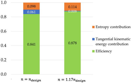
Figure 20.
Comparison of main loss contributions and efficiency at for two different rotational—.
7. Conclusions
Kaplan turbines can operate under low heads and large flow rates, allowing a wide range of high-efficiency operating points thanks to the conjugate double regulation of guide vane and rotor blade stagger angles. For very low heads (typically below 6 m) and small units (typically of power below 1 MW), a more economical solution is represented by tubular axial turbines with a simpler flow rate regulation operated by a single (only guide vane or rotor blade) variable stagger angle mechanism. The consequent drawback of this more economical solution is the significant reduction in the operating range due to the increase in off-design losses.
Nowadays, new possibilities for the design of simpler and more efficient low-head hydraulic turbines are opened by the adoption of new architectures based on a turbine direct-driven synchronous permanent magnet generator, equipped with a full electronic converter unit to decouple the turbine rotational speed, which shall be low for low heads, and the grid frequency, which is fixed and large.
The possibility of separating grid frequency and turbine rotational speed paves the way to an efficient concept of regulation of propeller hydraulic turbines for low heads, analyzed in this paper, based on the variation of the guide vane aperture, and on the simultaneous regulation of the rotational speed of the rotor.
First, a simple 1D meanline approach was carried out to demonstrate the concept through the application of the basic turbomachinery equations and classical loss correlations for axial flow turbines and to identify, as a first guess, the operating range limits of the new regulating concept.
Assuming as off-design losses the overall meanline rotor losses due to the residual tangential kinetic energy losses at the rotor exit and the profile losses, the first ones are by far larger than the latter in the case of simple guide vane regulation. The analyzed regulation system is capable of canceling or reducing significantly the tangential kinetic energy losses thanks to the variation of the rotational speed, while the effect on the profile losses is moderate with a tendency to increase with respect to the single guide vane regulation. However, considering the rotor overall meanline losses as the indicator of the regulation capabilities, the analyzed approach is clearly superior in enlarging the range of operation of the turbine under constant head both in terms of efficiency and reduced range of guide vane openings necessary to reach the desired flow rate variations.
With the aim of confirming what was deduced from the simple 1D theory and removing its inherent approximations, a complete 3D RANS analysis of the turbine off-design operation with single guide vane regulation and a regulation solution based on combined guide vane opening and rotational speed variations was developed. By means of the RANS approach, the turbine’s overall losses are calculated by summing the overall entropy production losses and the tangential kinetic energy losses. At some significant operating conditions, the local maps of entropy and consequent tangential kinetic energy losses were compared, and the main loss contributions and hydraulic efficiency were evaluated.
The RANS analysis confirms that, with the flow rate control based on combined guide vane opening and rotational speed variations, the range of operating flow rate is widened. In fact, the flow rate range of acceptable off-design operation, assumed as the range where the hydraulic efficiency remains above or equal to 0.9 of the design efficiency, was enlarged from for only guide vane regulation, to for combined guide vane opening and rotational speed variation with control strategy.
Author Contributions
Conceptualization, D.B., R.F., P.O., M.U. and P.Z.; methodology, D.B., M.U. and P.Z.; software, D.B.; validation, investigation, and data curation: D.B.; writing—review and editing, D.B., M.U. and P.Z.; supervision, D.B., R.F., P.O., M.U. and P.Z.; resources: R.F. All authors have read and agreed to the published version of the manuscript.
Funding
This research has been funded by a research contract of SEMI Industrial with the University of Genova on “Advanced design of hydraulic turbines”. Contract N.6798/2018.
Institutional Review Board Statement
Not applicable.
Informed Consent Statement
Not applicable.
Data Availability Statement
The data supporting the findings of the present study are available upon reasonable request to the authors.
Conflicts of Interest
The authors declare no conflict of interest.
Nomenclature
| Absolute velocity | Subscripts | ||
| Diameter | Referred to distributor inlet section | ||
| Gravitational acceleration | Referred to rotor inlet section | ||
| Lost head | Referred to rotor outlet section | ||
| Net head | Referred to rotor blade | ||
| Incidence angle | Reference design value | ||
| Tangential unit vector | Referred to turbine inlet section | ||
| Rotational speed coefficient | Referred to tangential kinetic energy | ||
| Flow rate coefficient | At meanline | ||
| Rotational speed | Referred to draft tube outlet section | ||
| Specific speed | Referred to profile | ||
| Total pressure | Referred to entropy | ||
| Turbine hydraulic power | Referred to blade tip | ||
| Volumetric flow rate | Total | ||
| Radius | Axial | ||
| Entropy | Tangential | ||
| Temperature or torque | |||
| Peripheral velocity | |||
| Relative velocity | |||
| Work exchange | |||
| Non dimensional wall coordinate | |||
| Incidence angle coefficient | |||
| Greeks | Acronyms | ||
| Absolute flow angle | Computational Fluid Dynamics | ||
| Guide vane opening angle | Best Efficiency Point | ||
| Relative flow angle | Reynolds Averaged Navier Stokes | ||
| Flow coefficient | Tubular Axial Turbine | ||
| Work coefficient | |||
| Turbine hydraulic efficiency | |||
| Density | |||
| Angular velocity | |||
References
- REN21. Renewables 2020 Global Status Report; REN21 Secretariat: Paris, France, 2021; ISBN 978-3-948393-00-7. [Google Scholar]
- Quaranta, E.; Bahreini, A.; Riasi, A.; Revelli, R. The Very Low Head Turbine for hydropower generation in existing hydraulic infrastructures: State of the art and future challenges. Sustain. Energy Technol. Assess. 2022, 51, 101924, ISSN 2213-1388. [Google Scholar] [CrossRef]
- Sari, M.A.; Badruzzaman, M.; Cherchi, C.; Swindle, M.; Ajami, N.; Jacangelo, J.G. Recent innovations and trends in in-conduit hydropower technologies and their applications in water distribution systems. J. Environ. Manag. 2018, 228, 416–428. [Google Scholar] [CrossRef] [PubMed]
- Krzemianowski, Z.; Kaniecki, M. Low-head high specific speed Kaplan turbine for small hydropower—Design, CFD loss analysis and basic, cavitation and runaway investigations: A case study. Energy Convers. Manag. 2023, 276, 116558. [Google Scholar] [CrossRef]
- Available online: http://voith.com/corp-en/hydropower-components/streamdiver.html (accessed on 15 October 2022).
- Available online: https://www.andritz.com/hy-hydromatrix (accessed on 15 October 2022).
- Barsi, D.; Ubaldi, M.; Zunino, P.; Fink, R. A new compact hydraulic propeller turbine for low heads. E3S Web Conf. 2019, 116, 1–9. [Google Scholar] [CrossRef]
- Barsi, D.; Ubaldi, M.; Zunino, P.; Fink, R. Optimized design of a novel hydraulic propeller turbine for low heads. Designs 2021, 5, 20. [Google Scholar] [CrossRef]
- Valentini, A. Generatori a Magneti Permanenti e Convertitori Statici di Frequenza: Nuove tecnologie per mini idro. In Proceedings of the Forum “Sfruttamento Idroelettrici su Bassi Salti”, AIET-TAA, Bolzano, Italy, 8 May 2014. (In Italian). [Google Scholar]
- Podio, F.; Mancuso, G. Mini Hydro-HPP Revamping_Generatori a magneti permanenti. In Proceedings of the Forum “HELE_High Efficiency Low Emissions”, ANIP, Milan, Italy, 27 September 2016. (In Italian). [Google Scholar]
- Borkowski, D.; Majdak, M. Small Hydropower Plants with Variable Speed Operation—An Optimal Operation Curve Determination. Energies 2020, 13, 6230. [Google Scholar] [CrossRef]
- Belhadji, L.; Bacha, S.; Munteanu, I.; Rumeau, A.; Roye, D. Adaptive MPPT Applied to Variable-Speed Microhydropower Plant. IEEE Trans. Energy Convers. 2013, 28, 34–43. [Google Scholar] [CrossRef]
- Denton, J.D. Loss mechanisms in turbomachines. Am. Soc. Mech. Eng. 1993, 78897, V002T14A001. [Google Scholar]
- Kacker, S.; Okapuu, U. A mean line prediction method for axial flow turbine efficiency. J. Eng. Power 1982, 104, 111–119. [Google Scholar] [CrossRef]
- Sutikno, P.; Adam, I.K. Design, simulation and experimental of the very low head turbine with minimum pressure and freevortex criterions. Int. J. Mech. Mechatron. Eng. 2011, 11, 9–16. [Google Scholar]
- Dick, E. Fundamentals of Turbomachines; Springer: Berlin/Heidelberg, Germany, 2015. [Google Scholar] [CrossRef]
- Galvas, M.R. Fortran Program for Predicting Off-Design Performance of Centrifugal Compressors. NASA Technical Note (TN) No. E-7480, November 1973. Available online: https://ntrs.nasa.gov/citations/19740001912 (accessed on 15 October 2022).
- Ainley, D.G.; Mathieson, G.C.R. A Method of Performance Estimation for Axial-Flow Turbines; Aeronautical Research Council Reports & Memoranda: London, UK, 1957. [Google Scholar]
- Dunham, J.; Came, P.M. Improvements to the Ainley-Mathieson Method of Turbine Performance Prediction. ASME J. Eng. Power 1970, 92, 252–256. [Google Scholar] [CrossRef]
- Cadence, User Manuals; Academic R&D License 2022; Cadence Design Systems, Inc.: San Jose, CA, USA, 2022.
- Spalart, P.R.; Allmaras, S.R. A one equation turbulence model for aerodynamic flows. In Proceedings of the 30th Aerospace Sciences Meeting and Exhibit, Reno, VA, USA, 6–9 January 1992. [Google Scholar]
- Derakhshan, S.; Mostafavi, A. Optimization of GAMM Francis Turbine Runner. World Acad. Sci. Eng. Technol. 2011, 59, 717–723. [Google Scholar] [CrossRef]
- Borkowski, D.; Węgiel, M.; Ocłoñ, P.; Węgiel, T. Simulation of water turbine integrated with electrical generator. MATEC Web Conf. 2018, 240, 05002. [Google Scholar] [CrossRef]
- Borkowski, D.; Węgiel, M.; Ocłoń, P.; Węgiel, T. CFD model and experimental verification of water turbine integrated with electrical generator. Energy 2019, 185, 875–883. [Google Scholar] [CrossRef]
- Hakimi, N. Preconditioning Methods for Time Dependent Navier-Stokes Equations. Ph.D. Thesis, Dept. of Fluid Mechanics, Vrike University, Brussel, Belgium, 1997. [Google Scholar]
Disclaimer/Publisher’s Note: The statements, opinions and data contained in all publications are solely those of the individual author(s) and contributor(s) and not of MDPI and/or the editor(s). MDPI and/or the editor(s) disclaim responsibility for any injury to people or property resulting from any ideas, methods, instructions or products referred to in the content. |
© 2023 by the authors. Licensee MDPI, Basel, Switzerland. This article is an open access article distributed under the terms and conditions of the Creative Commons Attribution (CC BY) license (https://creativecommons.org/licenses/by/4.0/).

