Abstract
The charging station has a vital role in the electric vehicle sector. The charging station provides supply (AC or DC) to vehicles as per requirements. The charging station infrastructure includes software and hardware that ensure energy transfer and safety. Communication is mandatory to transmit messages that contain information from the battery management system and charger. This research focuses on implementing the communication between the charger controller and the battery management system. This paper adopts the controller area network (CAN) bus charger communication protocol based on the SAE J1939 standard from the Society of Automotive Engineers. The data are transmitted over a network to facilitate the information that is to be conveyed by an electronic control unit. The vehicle communicates via the battery management system to the charger controller using CAN communication. The charger power modules with AC to DC and DC to DC converters uses Modbus communication protocol. Therefore, this paper integrates CAN bus and Modbus communication protocols and implements the communication between charger and electric vehicle battery management system using a cost-effective Arduino UNO micro-controller. Using the CAN bus module (MCP2515) and Modbus module (MAX485), the distance between the electric vehicle and the charger is increased. Finally, the communication is validated using PCAN View software.
1. Introduction
An effective alternative for charging electric vehicles (EVs) is renewable energy sources [1]. On the other hand, the majority of resources provide new issues, as they do not support modulated or straightforward forecasting of generation [2]. A large utilization of renewable sources could lead to encroachments, power declines and hence a lack of efficiency and power system unpredictability. EV-specific intelligent control systems may be a crucial component in bridging the gap between meeting transportation needs and generating energy from renewable sources [3]. The first essential component to take into account is intelligent charging. This word refers to all the control strategies that aim to recharge the vehicle’s battery whenever possible [4]. The intelligent charging adoption may smooth the additional peaks and reduce the need for additional power [5].
Moreover, it reduces the transportation sector’s costs and emissions by allowing for more effective use of generation sequencing technologies and leveraging cleaner technology where possible [6]. It is important to integrate the information and communication system to regulate and manage the energy transfer between the EVs and the power grid [7]. Implementation of communication technologies is carried out with detailed analyses of appropriate technologies and standards to support system frameworks [8]. Most of the communication standards are in progress, as it is an evolving technology. The standards and techniques are categorized into three groups: (1) Systems essential for home charging devices and transfers of messages between EV and charging equipment; (2) Mobile EV communication systems; and (3) Communication inter-control center standards [9].
Currently, the power grid restricts grid operators to install a greater number of EV charging stations. Thence, the power should be balanced among neighboring stations by using communications infrastructures [10]. Furthermore, while pre-charging, charging, and post-charging, the coordination between the vehicle and the charging station is essential. The EV and the charging unit must be connected to start the charging cycle for identification and authorization purposes. Furthermore, other information including charging time, power flow direction, power availability, energy cost and EV status are required to share between EV and charging station during charging. The communication standards for vehicles and charging stations [11,12,13,14,15,16,17,18] have been governed by the Society of Automotive Engineers (SAE) and are shown in Figure 1.
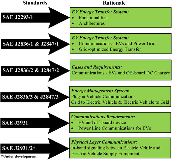
Figure 1.
SAE Communication Standards for EV Charging [11,12,13,14,15,16,17,18].
In addition, the International Electrotechnical Commission (IEC) is industrialized numerous guidelines for the DC rapid charging alternative under development. IEC 61851-23 sets out specifications for gird links and Fast Charging (FC) contact systems. IEC 61851-24 forms the concept of digital contact between EVs and charging stations. The SAE Subcommittee on vehicle control and communications has recognized a procedure for the proposal and usage of devices that communicate electronic indications and control data between EV components. The communication requirements between an EV and a charging facility at different locations are shown in Figure 2.
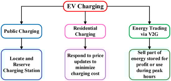
Figure 2.
Electric Vehicle Charging Requirements.
SAE J1939 and its equivalent services soon became the approved manufacturing standard [19]. J1939 is a higher-layer CAN-based protocol. It carries communication between electronic control units (ECUs) and sensory units. Data including vehicle speed, torque, engine transmission, power availability and temperature(s) will be exchanged between these systems. The specifications and features of SAE J1939 are presented in Table 1.

Table 1.
SAE J1939 Specifications and Features [19].
However, CAN communication is not appropriate for network administration and communications with higher than eight bytes of data. Thence, the higher-layer protocols such as SAEJ1939 for vehicles were designed to provide an enhanced networking infrastructure that supports unlimited-length messages and enables network control, including the use of node IDs. The implementation of communication between the charger controller and the battery management system is the main goal of this research. According to SAE specifications and MODBUS protocols, the information is transmitted over CAN in an expanded 29-bit ID format. The battery management system (BMS) and charger controller are connected by the vehicles through CAN communication. The Modbus communication protocol is used by the charger power modules with AC to DC and DC to DC converters. The objective is to reduce the cost of the project. Therefore, using cost-effective ATMEL micro-controllers, this research integrates the CAN bus and Modbus communication protocols to enable communication between the charger and the electric vehicle’s BMS. The distance between the electric car and the charger is extended using the CAN bus module (MCP2515) and Modbus module (MAX485). The communication is then verified using the PCAN View software.
The overall paper structure is as; Section 2 discusses the various elements and their function of electric vehicle energy management and charging communication system with a schematic. Section 3 discusses various modes of charging and the different levels of voltages adapted for charging the electric vehicle. Furthermore, the electric vehicle charging sequence and control communications are briefly discussed. In addition to that, the two communication protocols CAN bus SAEJ1939 and MODBUS are explored. In Section 4, the electric vehicle charging communication system is implemented using SAE J1939 CAN protocol and MODBUS protocol with Arduino microcontroller. Finally, the research work if concluded in Section 5.
2. E-Vehicle Energy Management and Charging
Electric vehicles are enabled by high-efficiency electric motor drives with high-performance controllers and batteries, which are powered by internal and external energy sources [20]. The electric vehicle consists of an energy management unit, power control unit, battery management unit, charge control unit, electronic control unit, and monitoring and communication system [21]. This section discusses various components and their function in electric vehicle energy management and charging communication systems.
The conceptual representation of vehicle energy management and charging communication systems are shown in Figure 3.
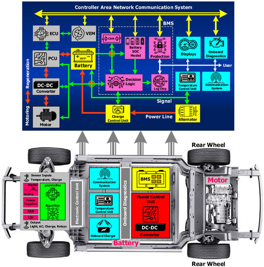
Figure 3.
Energy management and charging communication.
2.1. Vehicle Energy Management with Power Controlubsection
Vehicle energy management (VEM) and power control unit (PCU) are used for managing the energy flow between the battery and motor drive. The energy control module receives instructions from the BMS, vehicle sensors, and vehicle operator through the communication bus. Typically, the goal of the energy management unit is to optimize energy consumption. The VEM unit computes the electric motor’s power requirement based on the user’s acceleration and estimates the available battery charge [22]. The estimated information is provided to the PCU which provides the power to the motor drives through the bi-directional DC to DC power converters. ECUs are deployed for the managing the overall engine operations, which measures the parameters including acceleration, transmission and ambient conditions from vehicle sensors [23]. ECU transmits required details such as air parameters, the volume of fuel pumped and the frequency of the ignition to other peripheral vehicle equipment to ensure optimal working conditions. ECU also serves to set and monitor parameters for vehicle operating mode. This module is also called the personality module because it contains all the individual specifications that might be unique to the configuration of the customer for programming in the framework. The personality module interfaces through the CAN bus with the ECU. This module provides for the setting of the desired battery state of charge (SOC) functional level and the variables for controlling the electric drive. The vehicle energy management module also provides a memory block to store all the reference data and to collect the past data used to track the battery’s health. The vehicle instrumentation module can receive data through CAN bus to show the state of health (SOH) or turn ON warning lights. The vehicle energy module outputs provide the points of reference for setting the battery’s operating conditions or triggering protective circuit action. A typical RS232 or RS485 serial bus provides test access to BMS for testing or setting device parameters, and also for retrieving the battery history.
2.2. Battery Management System
The BMS determines the quantity of energy from running batteries that are utilized in EVs with higher precision, and also tracking and control of batteries. The BMS controls charging and discharging, cell balance, connection to the high voltage line and cooling [24]. The BMS is a microprocessor-based unit that integrates multiple functions and sub modules that are not actually distinct physical units but are seen for clarification separately here.
2.2.1. Battery SOC Model
The SOC battery model is an algorithm for determining the behavior of the battery in response to different internal and external circumstances. The SOC model logs past history to predict the battery state at any time for service purposes or to estimate the travelling distance of the electric vehicle until the battery needs to recharge. The distance traveled is extracted from data made accessible on the CAN bus by sensors. Calculating the battery SOC for the above-noted functions is an integral feature of the battery model [24]. The SOC is calculated basically by averaging the current flow over a period and lessening the value from the fully charged battery rating. The residual amount of charge is determined from the present SOC and the energy expended and the miles traveled, depending on latest driving trends. For electric vehicle battery is the only source, hence the precision of the level calculation is more important [25]. If a cell fails, the contactors will use the other (good) half of the battery to isolate and bypassing the half of the battery comprising the fault cell which allows the vehicle to limp home at half power. Model outputs are sent to electric vehicle displays, by means of the CAN bus as well.
2.2.2. Decision Logic (DL) Module
The DL module matches the SOC model’s measured or estimated battery parameters to the expected or referred outcome of the module. The DL circuits then supply error signals to trigger cell safety behavior or to be included in the specific BMS feedback loops that push the device to its optimal operating point or to separate the battery in abnormal operating conditions [26]. All these error signals are provided to the battery control unit for further processing. Certain relevant battery management system roles are as follows;
- Battery isolation during fault conditions
- Responding to vehicle operating mode changes
- Cell balance-offset defects in individual cells
- Responding to shifts in modes of operation of vehicles
- Binary control and progressive control-limiting overload
- Shift the regenerative braking power into the battery as needed
- Discard unnecessary regenerative braking charges with fully powered batteries
2.3. EV Charge Control Unit
The battery charge control unit mainly consists of power electronic circuitry that switches the power connections to individual cells. The power electronic switches are driven by the control signals from the battery monitoring unit for charging and discharging process [27]. The process of charging and mode of charging are predefined with specific algorithms and conditions. The communication system plays a significant role in EV charge control unit which should consider the various security standards.
2.3.1. Constant Current and Constant Voltage Charging Mode
The constant current (CC) charging method changes the output voltage of charging equipment or the resistance with the battery to maintain the current constant [28]. It maintains the current constant from start to finish charging. While the battery’s acceptable current capacity gradually decreases as the charging process progresses, this leads to the overloading of the battery during the early charge period. This would inevitably trigger a sharp reduction in battery power. Similarly, the constant voltage (CV) charging method maintains constant voltage between the battery poles [28]. When the vehicle is running, the starter battery is charged using constant voltage charging mode. If the value of the specified voltage persistent is suitable and can guarantee full battery charging.
2.3.2. CC-CV Switching Algorithms
Instead of using separate CV and DC charging methods during the charging cycle, CC-CV switching algorithms are used to integrate the two charging techniques, which enhances the charging power. In CC-CV switching algorithms, the CC mode is used to increase the battery’s charge by 90% in the first stage, and then altered to CV mode for fully charging the battery in the second stage. Because of the initial higher charge voltage, the CC-CV can charge the battery quicker than the CC or CV, but it is mandated that the battery should be released completely until charging. Since the charger must supply variable voltage, all elements must accept the maximum voltage developed by the boost charger [29]. Upon recharging the battery must be drained, as this would impact the charging power process and the life cycle of the device. Hence a dedicated algorithm is preferred for switching the charging mode depending on the charge level and discharging the battery.
2.3.3. Multi-Step Current Charging Algorithm
Multi-step current charging splits the charging cycle into several stages which aim to optimize the charging efficiency by using the optimal charging current in each phase. By identifying the optimum charging current for each step, the advanced control algorithm is used by temperature change to ascertain the charging current [29]. To sum it all up, the algorithm relies on a computer or a microcontroller. The charging speed is quicker, and the performance of charging is better than that of the CC-CV, controlling voltage and current profile of the charger output during the charging process, and giving additional charging to single cells to stabilize charge into all cells of the batteries.
2.4. Electronic Control Unit
Electronic control units, or ECUs, are typically found in electric vehicles. The number of ECUs in some high-tech electric vehicles can reach up to 80 ECUs. The integrated ECU application keeps increasing the line count, complexity and sophistication. A major challenge for original equipment manufacturers (OEMs) is how to manage a large number of ECUs inside cars. The ECU processor is mounted on a multi-layer circuit board containing hundreds of elements [23]. In the ECU, the communication system plays a significant role and should consider the various security standards. Various protocols are being used, but the one that starts controlling in-car communications is CAN. This transmission level facilitates data, velocities up to 500 kilobits per second (kbps). Such speed is becoming important because several modules, hundreds of times a second transmit data on the bus. The CAN bus communicates by way of two cables. Some of the further ECU components supporting the processor are as follows.
2.4.1. Analog and Digital Converters with Signal Conditioner
The outputs from the vehicle’s sensors are read by a low-level analog-to-digital converter module. Typically, a sensor’s analogue voltage ranges from 0 to 1.5 volts. The analog-to-digital converter converts this voltage into a binary 10-bit integer since the processor only recognizes digital numbers. Additionally, the sensor’s output signal must be “conditioned” to remove the noises. Similarly, a low-level digital-to-analog converter module provides an analog voltage output to operate some components of the EV system. Since the processor on the control unit is a digital system, a part is required which can convert the digital to analog signal. It is necessary to condition the controller’s output signal before using it to read the voltage and modify the level of an incoming or outgoing signal.
2.4.2. High-Level Digital Output
The ECU ignites the spark plugs in modern cars. The ECU opens and closes the fuel injectors as well as turning ON and OFF the cooling fan. The small amount of power from the processor will energize the digital output transistor, however, enabling the cooling fan relay to be supplied with a much larger amount of power. Hence, a voltage amplifier or driver circuit is required to obtain the high-level digital output.
2.5. Monitoring and System Communications
Improved condition monitoring of the various EV system elements can reduce in-use failures by identifying the degradation prematurely. Especially, the monitoring of electrical and thermal parameters will have an accurate prediction. These monitoring data and decision status are also part of on-board diagnostic services which are responsible for monitoring all of the systems [30]. The exchange of information between nodes, elements and operators is carried out through the CAN bus system.
2.5.1. Monitoring System
Worldwide EV manufacturers are concentrating on fast charging, which means the electrical and mechanical systems inside the car will be able to withstand high power. Hence, every subsystem in an EV includes temperature control. To protect onboard power transformers, switches (MOSFET/IGBT/SiC) used in DC-DC converters and inverters, magnetic power components, heat sinks, PCB, etc., monitoring and stable cooling control are mandatory. Even the BMS requires precise resolution of cell-level temperature estimation [31]. Overall, in order to protect the devices, the temperature sensor should be reliable. The precise temperature information helps the processor adjust the device for temperature so that the electronic modules can improve output and increase their efficiency independent of driving conditions.
2.5.2. Communication System
The CAN buses are the nervous system of EVs, it enables communication among all parts. Likewise, ‘nodes’—or electronic control units (ECU), are associated via the CAN bus, which serves as a central networking system. CAN standard makes a difference as it allows ECUs to communicate together without intermittent complex dedicated cabling [30]. It enables certain features through software, through CAN ECU connect with the whole system without allowing the controlling device to overload. The CAN bus is primarily adapted, due to low cost, centralized communication, robustness, efficiency and flexibility.
2.6. Charging Modes and Level
The battery mode includes lithiumions from just a positive electrode that passes across a separator/electrolyte. After this, the ions move to the negative electrode, via the solid electrolyte interface and intercalate. The potential negative effect of fast charging is that the unpredictable solid electrolyte interface can accelerate battery ageing, due to multiple charging and discharging [4]. Many methods depending on the charging time and charging infrastructure have been utilized for recharging electric vehicle batteries [32].
2.6.1. Modes of EV Charging
Charging is the main factor of the electric vehicle, and hence it is mandatory to provide a reliable charging system [33]. EV charging systems are in various forms, the IEC standard for EV charging systems (IEC 61851-1) has been well-defined in [34], and the four modes of EV charging are shown in Figure 4.
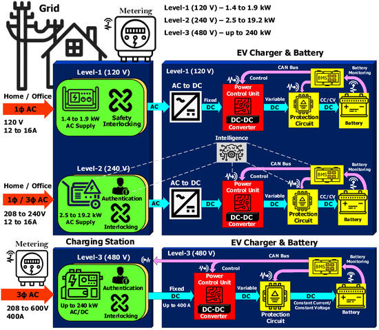
Figure 4.
Communications model of different charging modes.
- Mode 1: Domestic socket with an extension cord and without protection
Since the charging socket shares a switchboard feeder with other sockets, if the total current reaches the safety limit, the circuit breaker trips that interrupt charging. The vehicle is directly connected to the power grid through standard domestic socket outlets which are usually rated at about 5 to 10 A depending on the region. The electrical system must adhere to the safety guidelines to use mode 1; it must have an earthing device, earth leakage protection and overload protection. There are blanking devices in the sockets to avoid accidental contact. On the other hand, the limitations of mode 1 charging units are; heating of the socket and cables; fire or electric injury risks.
- Mode 2: Domestic socket with extension cord and protection
The vehicle is connected via domestic socket outlets to the main grid. Charging takes place via an available network, and an earthing cable is installed. Inside the unit, the cable and sockets are protected. Despite the wire’s specificity, this approach is more costly than mode 1.
- Mode 3: Slow charging devoted socket with protection
The vehicle is attached via a particular socket and a dedicated circuit to the electricity system. Only a feature of control and safety is permanently mounted in the system. This is the only charging mode, which meets applied electrical installation regulatory standards (IEC 61851). It also enables power failures so that electrical home appliances can be controlled throughout vehicle charging, or the electric vehicle charging time can be optimized on the opposite.
- Mode 4: Fast charging devoted socket with protection
The EV is attached by an external connection to the central power grid. Installation is permanently installed with control and protection features. New pulse loading with improved solid electrolyte interface stability. The new loading method also decreases the extra chemical reaction, and hence the battery life cycle and effectiveness are improved. In battery transfer charging stations, the distribution program is used to refuel electric cars. Most states, automobile makers, and internet charging companies tried to create these networks with the adaptable communication system.
2.6.2. Charging Level
Understanding the charging behavior of an electric vehicle is mandatory for adapting the suitable charging level [35]. It is preferred to use a level-1 charging system for low strength, a level-2 charging system for medium strength, and a level-3 charging system for high strength, shown in Figure 4. This charging system involves the AC to DC conversion, the power control mechanism that provides the battery with a regulated DC voltage, and filters. The battery management system (BMS) is an essential part of the EV. It measures the main electrical parameters of the battery and regulates the charging rate to provide correct constant current/voltage charging profile. It also activates the safety circuits and isolate the battery if the battery reached its operating limits. It adapts CAN bus features to integrate with other EV systems.
Level-1 charging stations are deployed with single phase supply and the protection circuit is relatively simple. It consists of a floor fault-sensing device and a circuit breaker. The charger itself typically includes additional comprehensive protection features in addition to the usual BMS functions. These features include protection interlocks and isolators to prevent the battery or the charger during fault conditions, as well as safeguards against power theft and electric shocks. The advantages of a level-1 charging system such as low power (up to 1.9 kW), low cost and low impact on utility peak demand. However, the charging speed is much slower.
Level-2 charger is designed and developed by communication intelligence that verifies and authorizes the user before transferring the power to charge the electric vehicle. The input power of the charger may be a single-phase AC supply with a power rating between 2.5 kW and 19.2 kW. Compared to the level-1 charger, the level-2 charger is quite faster in charging. Usually, level-2 chargers are employed in shopping malls, offices and dedicated charging stations. Similar to the level-1 charger, the level-2 charger is flexible to connect to various AC charging sources. The advantages of level-2 chargers are more efficient and fast charging compared to the level-1 charger. However, level-2 is costlier than the level-1 charger, also, it creates an impact on peak demand.
Level-3 chargers’ features are identical to those of level-1 and level-2 chargers, however, because of the incredibly high-power levels employed, the components of level-3 chargers require heavy-duty modules. The input power of the charger needs a dedicated three-phase AC supply with a power rating can be up to 240 kW. It makes logical sense to implement a level-3 charger in the charging station with multiple tapping so that multiple users can share the facilities. The level-3 charger is highly efficient and super-faster than the level-1 and level-2 chargers. However, it is much costlier than the other level chargers. The level-3 charger can be accommodated only in public charging, also, it creates a huge impact on peak demand.
3. Charger and Vehicle Communication
The EV charger may be housed on-board or off-board. The onboard charger is designed for the specific electric vehicle battery model and size. The battery can be charged by connecting the charger’s power inlet to the dedicated socket. On the other hand, the off-board electric vehicle charger requires communication with the battery control system for charging the batteries [30]. The communication protocol may be independent of the vehicle model. Hence, off-board chargers are designed to adapt to multiple technologies and standards of BMS. This off-board charge provides more benefits than on-board chargers including faster charging, lesser size and weight. This section interpreters the charging sequence and their control communications of electric vehicles and is followed by a brief discussion on the CAN SAEJ1939 protocol and MODBUS protocol.
3.1. Charging Sequence and Control Communication
The EV charger charges the battery using the CC or CV or CC-CV charging methods considering the vehicle control system as the master and the charger control system as a slave. The charging control process enables after initiating the charge button ON. Until receiving the charging permission from the vehicle communication system, the charger will not provide power to charge the vehicle [34]. The output is provided according to the charging current request and transmitted by the vehicle to the charger through CAN communication. Once the order value of the vehicle is notified through CAN communication, within the cycle of 100 milliseconds the system changes its order value. The detailed charging sequence and control communication between the charger and the electric vehicle is shown in Figure 5.
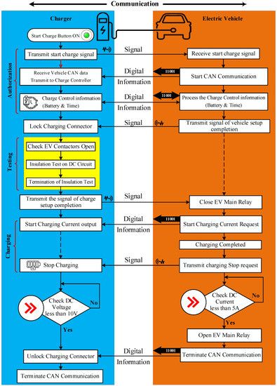
Figure 5.
Charging sequence and control communications.
3.2. CAN Bus SAEJ1939 Protocol
Electric vehicle data including torque, speed of the transmission system, engine temperature, oil level, battery level, and other signals from various parts are shared through the CAN interface [36]. CAN is a serial network system for the automotive sector [37]. CAN delivers rapid communication between ECUs, real-time sensing and control systems. CAN is a two-wired, half duplex ultra-speed network, which is upright in terms of flexibility and reliability of traditional serial systems such as RS232. CAN reduce the costly and complicated dual port infrastructure [38]. The charging sequence and control communications of the CAN bus are shown in Figure 6.
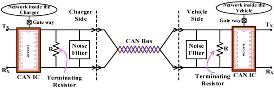
Figure 6.
CAN bus communication circuit.
CAN is not ideal for systems involving minimal network management, but also for signals higher than 8bytes of data. This result, higher layer protocols i.e., integrating additional software on the CAN physical layer to provide an advanced network system that can facilitate unlimited-length messages. Furthermore, it allows network management using node IDs. CAN bus communication is enhanced by the SAE J1939 standard, it is a higher-layer software-based protocol [37]. In addition to the usual CAN bus capabilities, SAE J1939 endorses node addresses and can receive data blocks over 8 bytes (up to 1785 bytes).
The SAE J1939 is meant to simulate the J1708 and J1587 functionality along with the support for the control system [19]. J1708 or J1587 requirements are typically used in automotive applications. SAE J1939 is an ingenious protocol that takes full advantage of the CAN 29-bit message descriptor, which is an essential feature. SAE J1939 is set up to deal with parameter tables, instead of depending on a multitude of protocol features, it holds the real protocol at a comprehensible level. SAE J1939 does not follow the existing master/slave or client/server architecture as opposed to other CAN-based protocols [19]. The traditional multi-master theory, in which all other nodes are considered slaves and the master is the node that prevails in the bus mediation, also functions effectively. J1939 is a physical layer, used in commercial vehicle for communication. It supports both peer-to-peer and broadcast communication with a bit rate of 250 kbps. CAN transmit up to 1765 bytes of data using transport protocol (TP). There shall be a data circuit for CAN communication, which facilitates one-on-one communication between the vehicle and charger. Parameters for charge control (current order value, voltage/current measurement results, flags indicating charging/vehicle conditions, etc.) shall be exchanged via this communication circuit. From the programming point of view, it is essential to note the configuration parameter groups and their numbers. The message priority and the software node address reflect the 29-bit message as shown in Figure 7.
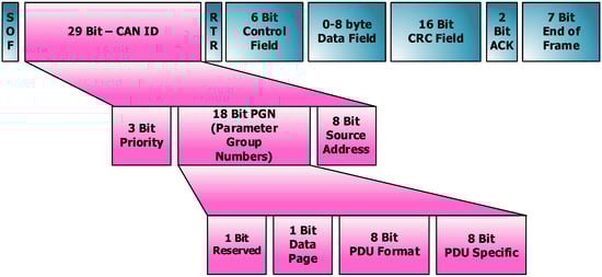
Figure 7.
CAN 29-bit message descriptor.
Twelve bytes of data are mentioned here, as the above 12 bytes and other data are optional, it is not mentioned. The complete data are written in the program and hence the connection management method is used. The charger provides electricity when the BMS requests it. It can comprehend the supplied and necessary energy by analyzing the CAN messages. This process has a specific format by which the CAN messages are sent and received. The following should be included in the communication between the BMS and charger, per SAE J1939;
- The standard CAN messages must contain 8 bytes of data
- The messages containing more than 8 bytes of data should be sent by multi-packet message
There are two types of multi-packet messages, broadcast announcement messages and connection management. In broadcast management, the entire network will receive these messages. Hence, the connection management protocol is employed in this work for security reasons.
3.3. Modbus Communication Protocol
The Modbus is the most popular automation open protocol. Modbus lets computers and appliances communicate with each other in a common language. It is a system used to transmit information between electronic devices over serial lines. Modbus enables devices in a grid to transmit data to an ECU for comparison between various parameters connected to the same network [39]. The computer demanding the information is called the Modbus master in the Modbus scheme, and the devices receiving the information are Modbus slaves. There is one Master and up to 247 slaves in a typical Modbus network, each having a specific slave address from 1 to 247. Modbus messages are transmitted in plain form over the network on basic interfaces such as RS485 or RS232, and the network will be devoted to Modbus communication only [40]. Network serial master–slave Modbus communication is enabled with two-wire for sending and receiving lines. The master is allowed to contact specific slaves or start a broadcast to all slaves. A slave is any external computer that collects messages and transmits its reply message to the master using Modbus, such as an I/O transducer, switch, network drive or other forms of measuring instruments. Slaves return an answer to all message requests that are personally sent to them but do not respond to transmitted messages. Slaves do not send messages of their own and only respond to the master’s message inquiries. The Modbus data model does have a simple structure represented in four basic types of data as shown in Figure 8.
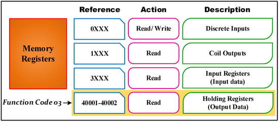
Figure 8.
Representation of MODBUS data structure.
The message or Modbus Protocol Storage Unit (PSU) service request field consists of a feature code, as well as the number of data bytes demanded from the operator [41]. A device’s Modbus memory registers are arranged in 4-basic data reference types. It is identified by a leading number that is used in the computer memory address.
- 0-based reference register to distinct outputs or coils in read or write code
- 1-based reference register reading separates inputs
- 3-based reference register reading input information and
- 4-based reference register is to read or write the data to output or store them
The function area code determines the set of data records; it reads or writes to and from the slave. The PSU fields are split down into bytes and formed by the name of the field. The feature code of 03, the beginning address HI and LO bytes of address 0000, and the count number of addresses to be read from the slave are all included in the request message. Register HI and LO bytes of count value 0002 specifies the beginning register and the number of registers to be read from the slave. From the driving relays, all the data types are named, for example, a single-bit physical output is called a coil, and a single-bit physical input is called a discrete input or communication.
The message’s function code field contains one byte that informs the slave to take appropriate action. Valid function codes range from 1 to 255, but not all codes will apply to a particular slave [40]. Figure 8 illustrates a subset of regular functions of Modbus. The master request data field also gives the slave certain additional details it needs to carry out the operation specified in the master’s request by the function code. Typically, this information includes the address of the slave map register, the number of registers that should be requested, and any written data from the master. The usual response of the slave merely repeats the request’s original function code, but the error response of the slave returns a code equal to the original function code with the most important logic-set bit 1. Add a custom code that notifies the master computer of what kind of problem happened or why the error occurred to the answer message data field.
4. Implementation of EV Charging Communication System
In this section, the EV charging communication system is implemented using the SAE J1939 CAN protocol and Modbus protocol with an Arduino microcontroller.
4.1. Charging Communication System Using SAE J1939 CAN Protocol
From the data logging point of view, SAE J1939 overlay with CAN which includes a series of uniform messages and transfer rules that extend to a wide variety of vehicles. The SAE J1939 protocol supports even more complex operations. This includes emails, communications with a multipack, multiplexing, and more [37]. Standalone J1939 data loggers based on CAN bus allow you to capture data, depending on the size of the SD card, over weeks or months of driving. In this paper, the goal is to integrate the Arduino controller (hardware) and SAE J1939 protocol stack (software). Prior to the Arduino series of microcontrollers, building even complicated embedded solutions required significant investments in embedded hardware and a solid trajectory. However, as with most other fields of embedded programming, such research now only requires modest investments in embedded hardware. Additionally, the availability of many extension boards, such as a shield for CAN buses, opened up a world of opportunities. Either the software (source code) is outrageously expensive or it comes with a royalty (object content, libraries), allowing for the use of the technology on a fee-based basis. That will improve, at least in the case of the Arduino hardware. The stack library for the ARD1939 protocol is available as a free download. Before we delve into an SAE J1939 protocol stack programming, certain fundamentals should be cleared including CAN shield hardware, Arduino hardware, and some special programming.
4.1.1. CAN Shield
The MCP2515 CAN controller IC and TJA1050 CAN transceiver IC is based on the CAN shield [42]. The MCP2515 IC is a standalone CAN controller and has a built-in SPI interface for microcontroller communication. MCP2515 IC is the key structure which consists of three internal sub-components: the CAN board, the control logic and the SPI block. CAN device is capable of sending and receiving messages via the CAN bus. Control logic manages the MCP2515 setup and service by interfacing all of its lines [43]. The SPI block is responsible for client SPI Communication. On the other hand, TJA1050 IC functions as an interface between the MCP2515 CAN controllers and the actual CAN bus. This IC is capable of taking the controller data and conveying it to the bus. Figure 9 illustrates the schematics of the MCP2515 module and how the MCP2515 IC and TJA1050 IC are attached to the board.
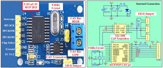
Figure 9.
CAN Control shield schematics—MCP2515 module with their internal connection.
4.1.2. Arduino and CAN Communication
An 8-bit Atmel AVR microprocessor was used to build the open-source Arduino UNO controller. It has 32 kB of memory chips (sketches), 1 kB of EEPROM, and 2 kB of RAM (non-volatile working memory). The CPU uses registers to temporarily store information, such as data to be processed or an address referring to data that has to be obtained. Timers, serial ports, I/O ports, and other types of hardware peripherals may all be programmed and controlled using special function registers. Three registers, which are also declared variables in the Arduino language, control each port. It is determined by the DDR register whether a pin is an input or an output. The PIN register reads the status of input pins set to input using pin mode, whereas the port register determines whether the pin is high or low. The details of registers are given in Table A1. The number of bits per second that the UART can transmit or receive is calculated as the baud rate. The baud rate for CAN bus is up to 1 Mbit/s. The SAE J1939 imposes a typical 250 kbit/s baud rate limit; but, recently, up to 500 kbit/s has also been used. To ensure proper communication between the charger and the BMS, both should operate at the same baud rate. If not, there will not be any communication and the data will be deleted. In this work, 250 kbit/s of baud rate is used for communication. For a proof of concept, these technical requirements are more than enough for practical prototyping of CAN bus and SAE J1939 applications. In this work, the software PCAN-View is used for viewing, transmitting, and recording CAN data traffic.
4.1.3. Delay Generation Logic
In order to effectively use the CAN bus, a specified time interval between two CAN messages (10 ms, 50 ms, 100 ms, 250 ms, and 500 ms). This period is stated in the SAE J1939 standard. To send the message after every 250 ms, the timer method is used in the program. There are three counter registers in Arduino UNO, namely, Timer-0, Timer-1 and Timer-2. These basic specifications are more than adequate for a proof of concept for realistic prototyping of CAN bus and SAE J1939 applications. The PCAN device is used for tracking and decoding CAN data and for sending and receiving CAN letters. The CAN messages are monitored via the software PCAN-View. So, the 16-bit timer-1 is used in this research. The timer calculations are given below:
Therefore,
To generate 100 ms delay,
4.1.4. Results and Discussion
The communication between the battery management system and the charger is extracted and analyzed using PCAN View software. The PCAN-View is a program for the tracking, transfer, and storage of CAN data traffic. Messages are transmitted manually and regularly at user-defined bit rate. During the operation, device bus errors and memory overflows are reflected in the CAN hardware. CAN data traffic can be registered and saved with the trace feature. PCAN-View comes with a PCAN PC hardware device and makes for fast and quick initialization. The link dialogue lists all available PEAK CAN interfaces. The user can access all device features, hardware-specific parameters, and information after choosing the hardware and bit rate. Figure 10 shows the communication between BMS and EV Charger.
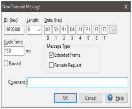
Figure 10.
Communication between BMS and Charger—Dialog box new transmit message.
Received CAN message: The CAN ID shown in Figure 11 is the extended 29-bit identifier which has the destination address 0x20 and source address 0x00. The length of the message is 8 bytes. The message has been received after the duration of 50 ms repeatedly for 20 times. The baud rate used for this communication is 1 MB/s.
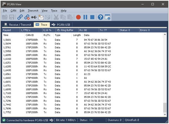
Figure 11.
PCAN Software Window—Recorded data.
Transmitted CAN messages: The message transmitted has the 29-bit identifier. The message length is 8 bytes. The destination address is 0x10 and the source address is 0x00. According to the requirement, cycle time can be varied. In this experiment, the data have been sent after 75 ms repeated 139 times. Consider the CAN standard as just having the lowest two tiers in the seven-layered OSI model, the fundamental physical layer and the data link layer. They provide the simplest means to connect small packets on the CAN bus, but not anything more. A higher layer protocol is facilitating connectivity through wide complex networks. For an instance, SAE J1939 defines how to treat multi-packet communications, i.e., when it is decided to transfer data greater than 8 bytes. Likewise, it defines how to turn data into human-readable text.
4.2. MODBUS Charging Communication System with Arduino Microcontroller
The charger consists of power modules i.e., AC to DC and DC to DC converters. The input supply to the charger is 400 V AC. These power modules convert the AC supply to the pulsating DC supply and the DC-DC converter gives pure DC at the output side. This power module supplies the energy according to the vehicle’s requirements. In EVs, to supply the controlled energy to drives and to avoid faults in the system, communication is required. So, in this paper, the Modbus protocol is implemented to communicate with the power modules, shown in Figure 12. Arduino UNO is used as a controller to communicate with the charger. By the use of the Modbus protocol, the commands such as voltage demand, current demand and power demand are sent to the power module.
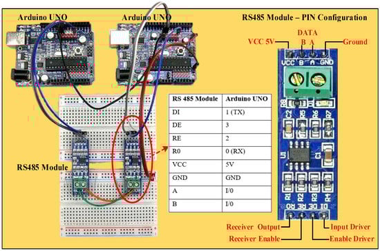
Figure 12.
Arduino connections with Modbus.
The RS485 serial data transmission standard serves as the foundation for the Modbus RTU protocol. MAX485 module is used to interact with the Arduino UNO microcontroller. The MAX485 and RS485 module transfers the TTL signal to RS485 for long-range, sequential communication, however, it is vulnerable to high data rate error. Digital communications networks implement the EIA-485 standard effectively over long distances and in environments with electrical noise. Multiple receivers may be connected to such a network in a linear, multi-drop configuration. Those features make those networks useful in both industrial and EV charging applications. This converter sends and receives data from an Arduino microcontroller using an RS485 network.RS485 is an industry-standard data transfer protocol that offers several benefits. It allows to transmission of data from up to 32 computers, with a maximum data rate of 10 Mbit/s, over the same phone line over a cable length of up to 1.2 km (4000 ft) [44]. This converter is designed for (non-isolated) office and industrial applications and offers superior properties that are usually seen only on costly systems.RS485 is the half-duplex communication, i.e., sending and receiving the data at the same time. To make it a full duplex, the two Arduino UNO with two MAX485 converters are to be used. The block diagram of the same is shown in Figure 13.

Figure 13.
Implementation of communication system using MODBUS with Arduino controller.
Data Communication
Data communication betweenRS485 and the microcontroller is transferred through the HEX code. To send the voltage and current as per demands, the data are converted into HEX. To power ON the module, the value of 01 is used, as well, the data for voltage and current are calculated as:
These values are required to write in the holding registers. To write these multiple values the function code 10(HEX) is used. Initially, the request is sent to the charger communication system to write the data, and then the charger responses to write the multiple values. Once the response is received, the data are read from the charger. This response comment with the corresponding remote terminal unit hex code is given in Table A2 to Table A5.
5. Conclusions
Communication has been carried out between the charger and the EV. Successful implementation of the CAN bus utilizing the MCP 2515 and microcontroller has allowed communication with the DC charger. Since RS485 is used for Modbus RTU communication, the distance between the master and slave was increased. The charger supplies electricity to EVs in accordance with demands owing to end-to-end communication and its control, which lowers the possibility of a fault occurring and enhances efficiency. The usage of low-cost, high-performance controllers such as the Arduino UNO, MCP 2515, and MAX 485 modules makes the work cost-effective.
Author Contributions
Conceptualization, A.A., S.M.W., V.I., R.R.S. and V.S.; methodology, A.A., S.M.W., V.I., R.R.S. and V.S.; investigation, A.A., S.M.W., V.I., R.R.S. and V.S.; writing—original draft preparation, A.A., S.M.W., V.I., R.R.S. and V.S.; writing—review and editing, A.A., S.M.W., V.I., R.R.S. and V.S. All authors have read and agreed to the published version of the manuscript.
Funding
The authors are thankful to the Deanship of Scientific Research at Najran University for funding this work under the National Research Priorities funding program grant code (NU/NRP/SERC/11/3).
Institutional Review Board Statement
Not applicable.
Informed Consent Statement
Not applicable.
Data Availability Statement
Not applicable.
Conflicts of Interest
The authors declare no conflict of interest.
Appendix A
Table A1.
Arduino UNO registers.
Table A1.
Arduino UNO registers.
| Details | Register Bit |
|---|---|
| Carry Flag | Bit 0–C |
| Zero Flag | Bit 1–Z |
| Negative Flag | Bit 2–N |
| Two’s Complement Overflow Flag | Bit 3–V |
| Sign Bit, S = N + V | Bit 4–S |
| Half Carry Flag | Bit 5–H |
| Bit Copy Storage | Bit 6–T |
| Global Interrupt Enable | Bit 7–I |
Table A2.
Request to write values to Charger.
Table A2.
Request to write values to Charger.
| Field Name | RTU (hex) |
|---|---|
| Slave Address | 01 |
| Function | 10 |
| Starting Address Hi | 00 |
| Starting Address Lo | 0A |
| Quantity of Registers Hi | 00 |
| Quantity of Registers Lo | 03 |
| Byte Count | 06 |
| Data Hi (voltage Hi Byte) | 13 |
| Data Lo (voltage Lo Byte) | 88 |
| Data Hi (Current Hi Byte) | 00 |
| Data Lo (Current Hi Byte) | 0A |
| Data Hi (Power Module ON) | 00 |
| Data Lo (Power Module ON) | 01 |
| Error Check Lo | C5 |
| Error Check Hi | DE |
Table A3.
Response from charger to Write Multiple values.
Table A3.
Response from charger to Write Multiple values.
| Field Name | RTU (hex) |
|---|---|
| Slave Address | 01 |
| Function | 10 |
| Starting Address Hi | 00 |
| Starting Address Lo | 0A |
| Quantity of Registers Hi | 00 |
| Quantity of Registers Lo | 03 |
| Error Check Lo | A0 |
| Error Check Hi | 0A |
Table A4.
Read values from charger.
Table A4.
Read values from charger.
| Field Name | RTU (hex) |
|---|---|
| Slave Address | 01 |
| Function | 03 |
| Starting Address Hi | 00 |
| Starting Address Lo | 0A |
| Quantity of Registers Hi | 00 |
| Quantity of Registers Lo | 03 |
| Error Check Lo | 25 |
| Error Check Hi | C9 |
Table A5.
Response to read multiple registers from Charger.
Table A5.
Response to read multiple registers from Charger.
| Field Name | RTU (hex) |
|---|---|
| Slave Address | 01 |
| Function | 03 |
| Byte Count | 06 |
| Data Hi (voltage Hi Byte) | 13 |
| Data Lo (voltage Lo Byte) | 88 |
| Data Hi (Current Hi Byte) | 00 |
| Data Lo (Current Hi Byte) | 0A |
| Data Hi (Power Module ON) | 00 |
| Data Lo (Power Module ON) | 01 |
| Error Check Lo | 22 |
| Error Check Hi | 0B |
References
- Yong, J.K.; Ramachandaramurthy, V.K.; Tan, K.M.; Mithulananthan, N. A review on the state-of-the-art technologies of electric vehicle, its impacts and prospects. Renew. Sustain. Energy Rev. 2015, 49, 365–385. [Google Scholar] [CrossRef]
- Rupp, M.; Handschuh, N.; Rieke, C.; Kuperjans, I. Contribution of country-specific electricity mix and charging time to environmental impact of battery electric vehicles: A case study of electric buses in Germany. Appl. Energy 2019, 237, 618–634. [Google Scholar] [CrossRef]
- Ahmadi, P. Environmental impacts and behavioral drivers of deep decarbonization for transportation through electric vehicles. J. Clean. Prod. 2019, 225, 1209–1219. [Google Scholar] [CrossRef]
- Chandran, V.; Patil, C.K.; Karthick, A.; Ganeshaperumal, D.; Rahim, R.; Ghosh, A. State of Charge Estimation of Lithium-Ion Battery for Electric Vehicles Using Machine Learning Algorithms. World Electr. Veh. J. 2021, 12, 38. [Google Scholar] [CrossRef]
- Capasso, C.; Veneri, O. Experimental study of a DC charging station for full electric and plug in hybrid vehicles. Appl. Energy 2015, 152, 131–142. [Google Scholar] [CrossRef]
- Nienhueser, I.A.; Qiu, Y. Economic and environmental impacts of providing renewable energy for electric vehicle charging–A choice experiment study. Appl. Energy 2016, 180, 256–268. [Google Scholar] [CrossRef]
- Banerji, A.; Sharma, K.; Singh, R.R. Integrating Renewable Energy and Electric Vehicle Systems into Power Grid: Benefits and Challenges. In Proceedings of the 2021 Innovations in Power and Advanced Computing Technologies (i-PACT), Kuala Lumpur, Malaysia, 27–29 November 2021; pp. 1–6. [Google Scholar] [CrossRef]
- Zhang, J.; Wang, Z.; Liu, P.; Zhang, Z. Energy consumption analysis and prediction of electric vehicles based on real-world driving data. Appl. Energy 2020, 275, 115408. [Google Scholar] [CrossRef]
- Kettles, D. Electric Vehicle Charging Technology Analysis and Standards. Appl. Energy 2016, 139, 60–67. [Google Scholar] [CrossRef]
- Quinn, C.; Zimmerle, D.; Bradley, T.H. The effect of communication architecture on the availability, reliability, and economics of plug-in hybrid electric vehicle-to-grid ancillary services. J. Power Sources 2010, 195, 1500–1509. [Google Scholar] [CrossRef]
- Scholer, R.A.; Maitra, A.; Ornelas, E.; Bourton, M.; Salazar, J. Communication between Plug-in Vehicles and the Utility Grid. In Proceedings of the SAE 2010 World Congress & Exhibition, Detroit, MI, USA, 12–15 April 2010; pp. 1–36. [Google Scholar] [CrossRef]
- Energy Transfer System for Electric Vehicles—Part 1: Functional Requirements and System Architectures. In Proceedings of the SAE International Surface Vehicle Information Report 2008 World Congress & Exhibition, Detroit, MI, USA, 7 July 2008; pp. 1–11. [CrossRef]
- Use Cases for Communication Between Plug-in Vehicles and the Utility Grid. In Proceedings of the SAE International Surface Vehicle Information Report 2010 World Congress & Exhibition, Detroit, MI, USA, 13–15 April 2010; p. 244. [CrossRef]
- Communication between Plug-In Vehicles and Off-Board DC Chargers. In Proceedings of the SAE International Surface Vehicle Standard 2015 World Congress & Exhibition, Detroit, MI, USA, 9 April 2015; pp. 1–177. [CrossRef]
- Use Cases for Communication between Plug-in Vehicles and Off-Board DC Charger. In Proceedings of the SAE International Surface Vehicle Information Report 2011 World Congress & Exhibition, Detroit, MI, USA, 15 September 2011; pp. 1–19. [CrossRef]
- Use Cases for Plug-in Vehicle Communication as a Distributed Energy Resource. In Proceedings of the SAE International Surface Vehicle Information Report 2013 World Congress & Exhibition, Detroit, MI, USA, 3 January 2013; pp. 1–130. [CrossRef]
- Communication for Plug-in Vehicles as a Distributed Energy Resource. In Proceedings of the SAE International Surface Vehicle Information Report 2013 World Congress & Exhibition, Detroit, MI, USA, 10 December 2013; pp. 1–93. [CrossRef]
- Digital Communications for Plug-in Electric Vehicles. In Proceedings of the SAE International Surface Vehicle Information Report 2010 World Congress & Exhibition, Detroit, MI, USA, 24 January 2012; pp. 1–33. [CrossRef]
- Recommended Practice for a Serial Control and Communications Vehicle Network. In Proceedings of the SAE International Surface Vehicle Information Report 2010 World Congress & Exhibition, Detroit, MI, USA, 9 October 2007. [CrossRef]
- Tie, S.F.; Tan, C.W. A review of energy sources and energy management system in electric vehicles. Renew. Sustain. Energy Rev. 2013, 20, 82–102. [Google Scholar] [CrossRef]
- Un-Noor, F.; Padmanaban, S.; Mihet-Popa, L.; Mollah, M.N.; Hossain, E. A comprehensive study of key electric vehicle (EV) components, technologies, challenges, impacts, and future direction of development. Energies 2017, 10, 1217. [Google Scholar] [CrossRef]
- Li, S.; Bao, K.; Fu, X.; Zheng, H. Energy management and control of electric vehicle charging stations. Electr. Power Compon. Syst. 2014, 42, 339–347. [Google Scholar] [CrossRef]
- Bayindir, K.Ç.; Gözüküçük, M.A.; Teke, A. A comprehensive overview of HEV: Powertrain configurations, powertrain control techniques and electronic control units. Energy Convers. Manag. 2011, 52, 1305–1313. [Google Scholar] [CrossRef]
- Cheng, K.W.E.; Divakar, B.P.; Wu, H.; Ding, K.; Ho, H.F. Battery-management system (BMS) and SOC development for electrical vehicles. IEEE Trans. Veh. Technol. 2010, 60, 76–88. [Google Scholar] [CrossRef]
- Frost, D.F.; Howey, D.A. Completely decentralized active balancing battery management system. IEEE Trans. Power Electron. 2017, 33, 729–738. [Google Scholar] [CrossRef]
- Li, S.G.; Sharkh, S.M.; Walsh, F.C.; Zhang, C.N. Energy and battery management of a plug-in series hybrid electric vehicle using fuzzy logic. IEEE Trans. Veh. Technol. 2011, 60, 3571–3585. [Google Scholar] [CrossRef]
- Amjadi, Z.; Williamson, S.S. Power-electronics-based solutions for plug-in hybrid electric vehicle energy storage and management systems. IEEE Trans. Ind. Electron. 2009, 57, 608–616. [Google Scholar] [CrossRef]
- Qu, X.; Han, H.; Wong, S.C.; Tse, C.K.; Chen, W. Hybrid IPT Topologies with Constant Current or Constant Voltage Output for Battery Charging Applications. IEEE Trans. Power Electron. 2015, 30, 6329–6337. [Google Scholar] [CrossRef]
- Shen, W.; Vo, T.T.; Kapoor, A. Charging algorithms of lithium-ion batteries: An overview. In Proceedings of the 2012 7th IEEE Conference on Industrial Electronics and Application, Singapore, 18–20 July 2012. [Google Scholar] [CrossRef]
- Ribbens, W.B. Chapter 9–Vehicle Communications. In Understanding Automotive Electronics, 8th ed.; Ribbens, W.B., Ed.; Butterworth-Heinemann: Oxford, UK, 2017; pp. 461–504. [Google Scholar]
- Affanni, A.; Bellini, A.; Franceschini, G.; Guglielmi, P.; Tassoni, C. Battery choice and management for new-generation electric vehicles. IEEE Trans. Ind. Electron. 2005, 52, 1343–1349. [Google Scholar] [CrossRef]
- Van Den Bossche, P. Electric vehicle charging infrastructure. In Electric and Hybrid Vehicles; Elsevier: Amsterdam, The Netherlands, 2010. [Google Scholar]
- Rahman, I.; Vasant, P.M.; Singh, B.S.M.; Abdullah-Al-Wadud, M.; Adnan, N. Review of recent trends in optimization techniques for plug-in hybrid, and electric vehicle charging infrastructures. Renew. Sustain. Energy Rev. 2016, 58, 1039–1047. [Google Scholar] [CrossRef]
- Zhou, Q.; Xu, Y.; Rasol, J.; Hui, T.; Yuan, C.; Li, F. Reliable Design and Control Implementation of Parallel DC/DC Converter for High Power Charging System. Machines. 2022, 10, 1162. [Google Scholar] [CrossRef]
- Franke, T.; Krems, J.F. Understanding charging behaviour of electric vehicle users. Transp. Res. Part F Traffic Psychol. Behav. 2013, 21, 75–89. [Google Scholar] [CrossRef]
- Landman, R.G. Design and analysis of CAN networks for vehicles. SAE Trans. 2000, 192–198. [Google Scholar] [CrossRef]
- Ran, L.; Junfeng, W.; Haiying, W.; Gechen, L. Design method of CAN BUS network communication structure for electric vehicle. In Proceedings of the International Forum on Strategic Technology 2010, Ulsan, Korea, 13–15 October 2010; pp. 326–329. [Google Scholar] [CrossRef]
- Sato, K.; Koita, T.; McCormick, S. Design and implementation of a vehicle interface protocol using an IEEE 1394 network. J. Syst. Archit. 2008, 54, 901–910. [Google Scholar] [CrossRef]
- Xuehua, S.; Min, L.; Hesheng, W.; Hong, W.; Fei, L. The solution of hybrid electric vehicle information system by modbus protocol. In Proceedings of the 2011 International Conference on Electric Information and Control Engineering, Wuhan, China, 15–17 April 2011. [Google Scholar] [CrossRef]
- Fovino, I.N.; Carcano, A.; Masera, M.; Trom-Betta, A. Design and Implementation of a Secure Modbus Protocol; Springer: Berlin/Heidelberg, Germany, 2009. [Google Scholar] [CrossRef]
- Belliardi, R.; Neubert, R. Modbus protocol. In Industrial Communication Technology Handbook, 2nd ed.; CRC Press: Boca Raton, FL, USA, 2017. [Google Scholar]
- Li, Z.L.; Liu, P.; Li, W. A multibyte data communication method based on MCP2515 CAN controller. Xi’an Shiyou Daxue Xuebao (Ziran Kexue Ban)/J. Xi’an Shiyou Univ. Nat. Sci. Ed. 2014, 5, 1. [Google Scholar]
- Microchip Technology, MCP2515–Stand-alone CAN Controller with SPI Interface (Datasheet). Datasheet, 2012. Available online: https://www.microchip.com/en-us/search?searchQuery=MCP2515&category=Product%20Documents|Data%20Sheets&fq=start%3D0%26rows%3D10 (accessed on 28 November 2022).
- Maxim Integrated, MAX485 TTL to RS485 Converter Modul e. Available online: https://www.techtonics.in/max485-ttl-to-rs485-converter-module (accessed on 21 April 2022).


Disclaimer/Publisher’s Note: The statements, opinions and data contained in all publications are solely those of the individual author(s) and contributor(s) and not of MDPI and/or the editor(s). MDPI and/or the editor(s) disclaim responsibility for any injury to people or property resulting from any ideas, methods, instructions or products referred to in the content. |
© 2023 by the authors. Licensee MDPI, Basel, Switzerland. This article is an open access article distributed under the terms and conditions of the Creative Commons Attribution (CC BY) license (https://creativecommons.org/licenses/by/4.0/).