Abstract
An electrically controlled rotor (ECR), also known as a swashplateless rotor, is an active rotor system that reduces the vibration load of the rotor through active control while achieving primary control by using a trailing edge flap system instead of a swashplate. In this study, the control effect of a 2Ω higher-order harmonic input on the vibration load of an ECR is investigated. First, an analytical aeroelastic model of the ECR is established based on Hamilton’s principle and an unsteady aerodynamic model with a flapped airfoil. On this basis, the use of higher-order harmonic flap control to reduce the vibration load of the ECR is investigated. The effect of the 2Ω higher-order harmonic flap control on the 2Ω vibration load of the example ECR is analyzed by sweeping the amplitude and phase of the higher-order harmonic flap control. The effect of higher-order harmonic flap control on the primary control of the ECR is also analyzed. The results show that the 2Ω higher-order flap deflection has the most significant control effect on the 2Ω vertical vibration load of the hub, that there is coupling between the higher-order flap deflection and the primary control of the ECR, and that the higher-order flap deflection disrupts the original equilibrium of the ECR.
1. Introduction
An electrically controlled rotor (ECR), also known as a swashplateless rotor, uses a trailing edge flap system to realize primary control of the rotor [1]. The elimination of a swashplate simplifies the control system of the ECR, which effectively reduces the weight cost and wasted power of a helicopter. At present, research on ECRs mainly focuses on feasibility analysis [2], noise alleviation [3,4], design parameter analysis [5], and performance improvement [6].
However, the rotor is not only the main lifting surface and control surface but also the main vibration source of a helicopter. When a helicopter flies forward, there is a difference in the speed relative to air between the advancing and retreating sides of the rotor, causing cyclic changes in the aerodynamic load of the blades during one revolution. Due to the filtering effect of the hub, the aerodynamic load, which changes once per revolution, eventually leads to a hub vibration load equal to an integer multiple of the number of blades, i.e., kNbΩ (where k = 1, 2, 3…; Nb is the number of blades; and Ω is the rotor speed) [7]. The existing active control methods for rotor vibration mainly include higher harmonic control (HHC) [8,9,10], individual blade control (IBC) [11,12,13], and active control flap (ACF) [14,15,16], which achieve vibration reduction by using higher-order deflection of blades or trailing edge flaps. Due to the elimination of the swashplate, the ECR’s trailing edge flap system can be used not only for the collective and cyclic pitch control of the rotor but also to offset the frequency vibration load of the hub by the higher-order flap deflection. To meet the primary control requirements of an ECR, the torsional stiffness of the blade root is usually lower than that of a conventional rotor, leading to an increase in the vibration load [17]. Therefore, there is a strong need to utilize the unique flap system of the ECR to achieve active vibration control.
Since the ECR is a complex nonlinear aeroelastic system, the extra active vibration control quantities (such as higher-order harmonic control) added while realizing rotor control are always coupled with the control quantities in the original primary control of the ECR, thus affecting the original trim state and, accordingly, the active flap vibration control effect. Therefore, this study first establishes an aeroelastic model of an ECR based on Hamilton’s principle, using element nodal displacements to express the variations of the strain energy and kinetic energy of the blades, and introduces the unsteady aerodynamic load as an external force into the dynamic system of the ECR. On this basis, an open-loop simulation of the active control of higher-order harmonic flap vibration is carried out while realizing the primary control of the ECR.
This paper consists of the following sections. Section 2 describes the aeroelastic model of the ECR based on Hamilton’s principle and an unsteady aerodynamic model of the flaps. In Section 3, the control effect of higher-order flap deflection with different amplitudes and phases on the vibration load of the ECR is firstly investigated, and on this basis, the effect of higher-order harmonic flap control on the primary control of the ECR is analyzed. Finally, the conclusions of this study are drawn in Section 4.
2. Aeroelastic Model of the ECR
2.1. Dynamic Modeling of the Blade
The nonlinear equation of motion of the flapped blade can be obtained from Hamilton’s principle as follows:
where U is the strain energy of the ECR blade, T is the kinetic energy of the blade, W is the virtual work performed by the external force, and t2-t1 is any time interval.
According to the engineering beam theory, the strain energy of the blade can be expressed as follows:
where is the tension of the blade cross-section
is the lag moment of the blade cross-section
is the flap moment of the blade cross-section
is the torque of the blade cross-section
where A is the area of the blade cross-section; and are the chordwise and vertical sectional static moments, respectively; and are the chordwise and vertical sectional inertia moments, respectively; and is the sectional polar inertia moment.
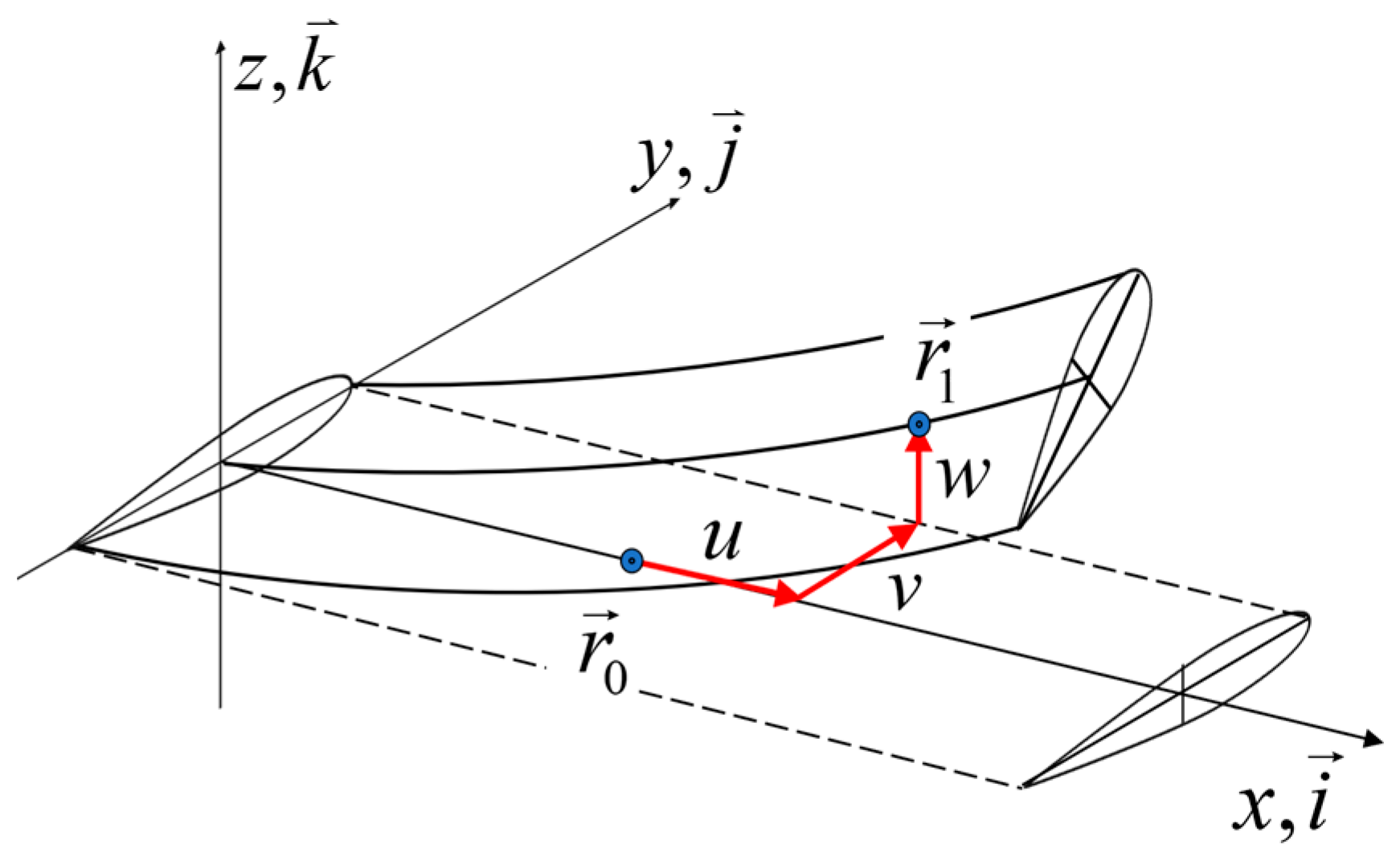
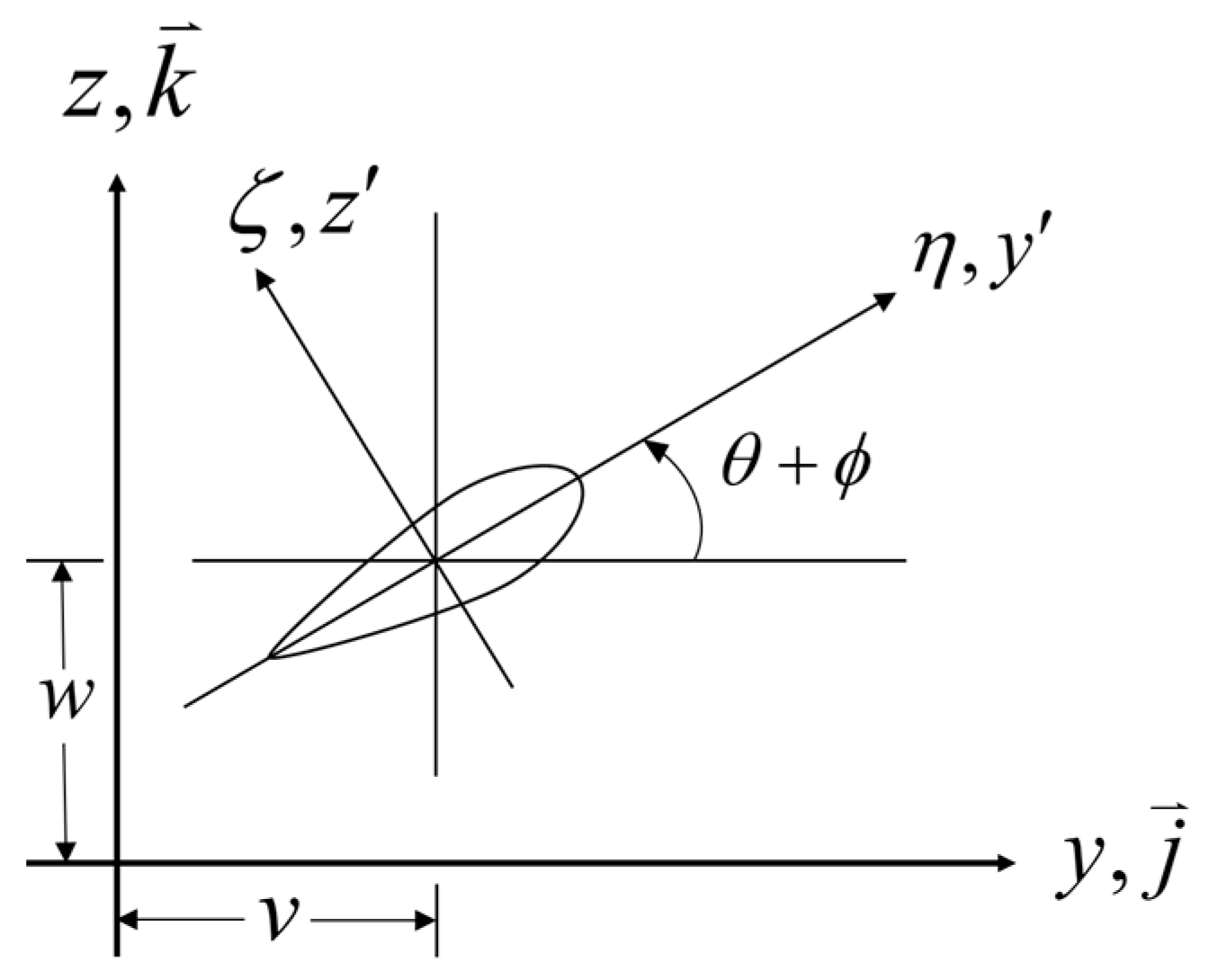
where u, v, and w are the spanwise, chordwise, and vertical deformations at any point of the blade (as shown in Figure 1), respectively; is the pre-twist angle at any point of the blade; is the vertical position of any point on the blade cross-section; and is the chordwise position of any point on the blade cross-section (as shown in Figure 2).

Figure 1.
Definition of blade deformation.

Figure 2.
Definition of blade cross-section coordinate.
For the convenience of numerical calculation, the blade was divided into a finite number of elements, and the displacement at any point of the blade is expressed in terms of generalized displacements at element nodes by appropriately selecting displacement shape functions. In this way, the strain energy of the blade can be expressed in terms of generalized displacements at element nodes, and the line integral operation along the entire blade can be transformed into discrete multiply–add operations by the Gaussian integral at element nodes.
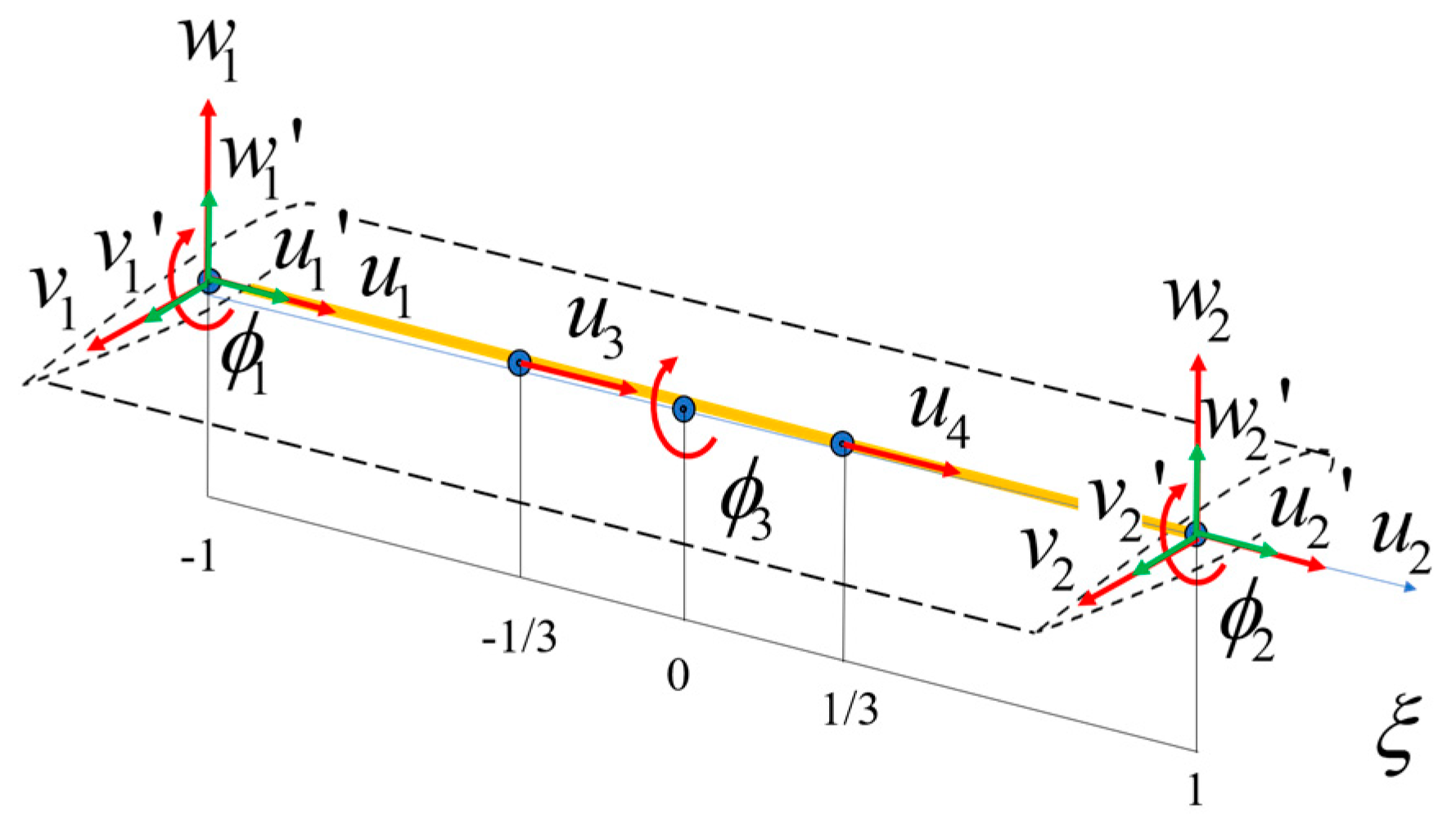
Since the centrifugal force acting on the blade varies quadratically along the blade axis, a total of four axial displacement nodes were arranged at the two ends and the interior of each element, and cubic interpolation functions were used to interpolate the axial displacement of the blade to accurately describe the characteristics of the secondary change in centrifugal inertia force along the blade axis. The twist angle varies quadratically along the axis, so three twist nodes were arranged at the two ends and the midpoint of each element. Cubic Hermite interpolation functions were used for the lateral displacement. Then, three rigid body degrees of freedom (DOFs) (flapping, shimmy, and twisting) of the blade were introduced, resulting in a total of five nodes and 18 DOFs of the beam element of the ECR blade, as shown in Figure 3.

Figure 3.
The arrangement of nodes and DOFs of the element of the ECR blade.
The parametric displacement at any point within an element can be expressed in terms of nodal displacements as follows:
where N is the displacement interpolation shape function. The expression of displacement at any point is substituted into the expression of the blade strain energy to obtain the variation in strain energy of the beam element as follows:
where is the generalized force caused by strain energy, and is the generalized displacement vector.
The rigid body motion of the blade does not cause the strain energy of the blade but affects the kinetic energy of the blade and the work performed by the external force. Therefore, three generalized displacements (flapping, shimmy, and twisting) of the blade rigid body were added to the above generalized displacement to form a rigid–flexible coupling element with 18 DOFs.
The kinetic energy term in Hamilton’s principle includes two parts: the virtual work of the inertial force caused by the flapping, shimmy, and twisting motions and the elastic vibration of the blade, and the virtual work of the inertial force caused by the flap deflection motion. The virtual work of the inertial force of the blade can be obtained by integrating the kinetic energy of the microelement at any position of the blade along the span direction of the blade. The kinetic energy of the microelement at any point of the blade is expressed as follows:
where is the position vector of any point of the blade.
The variation in kinetic energy of the entire blade is expressed as follows:
where is the generalized inertial force caused by the motion and elastic deformation of the blade.
To meet the needs of the primary control of an ECR, the trailing edge flaps of the ECR usually have a large size and a wide range of deflection. Therefore, the effect of the inertial force caused by flap motion cannot be ignored. The variation of flap kinetic energy is expressed as:
where is the generalized inertial force caused by flap motion.
The external force on the ECR blade is mainly the aerodynamic force distributed on the blade. The virtual work caused by the aerodynamic force is expressed as follows:
where is the generalized aerodynamic force corresponding to each generalized displacement, and R is the rotor radius.
2.2. Aerodynamic Modeling of the Blade
In the calculation of the generalized aerodynamic force, the lift, drag, and torque distributed on the blade surface can be obtained by using a subsonic unsteady aerodynamic model with a known incoming flow velocity. The velocity of each airfoil section relative to the air is composed of the blade motion velocity at the section and the incoming flow velocity :
where the incoming flow velocity is composed of the helicopter flight speed and the rotor induced velocity :
In this study, the rotor-induced velocity was calculated using a linear inflow model:
where is the advance ratio, is the total inflow ratio, is the induced inflow ratio, is the rotor thrust coefficient, is the azimuth angle, is the dimensionless spanwise position of the blade, and and can be determined according to Equations (18) and (19):
(1) When , the Black and White model is used:
(2) When , the Drees model is used:
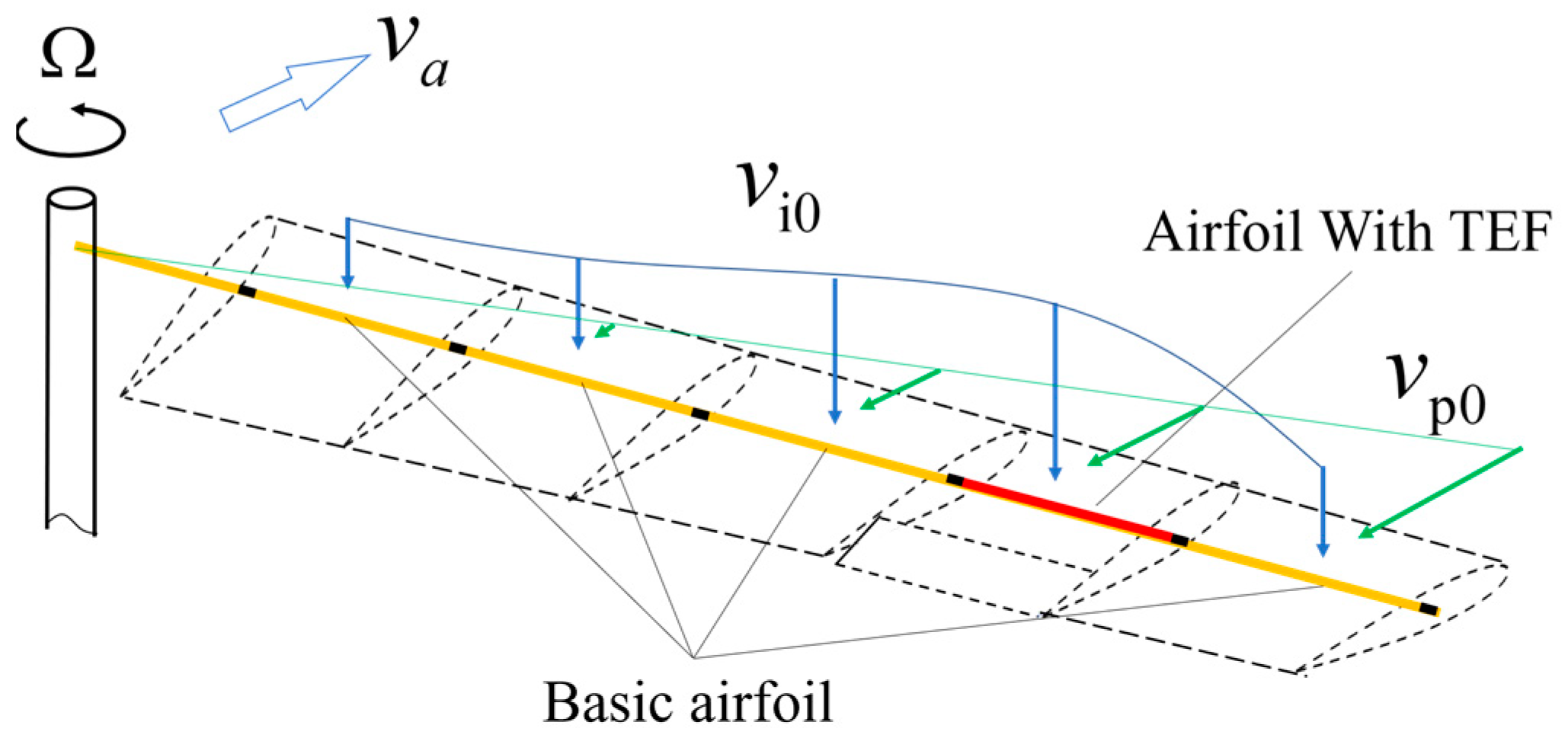
The aerodynamic force at each section of the ECR blade can be divided into two categories: that of the basic airfoil and that of the flapped airfoil, as shown in Figure 4. The exponential Leishman–Beddoes subsonic compressible unsteady aerodynamic model [18] is used as the aerodynamic model of the basic airfoil, and the aerodynamic model of the flapped airfoil consists of two parts: the aerodynamic model of the basic airfoil and the Hariharan subsonic compressible unsteady aerodynamic model [19] as the aerodynamic model of flaps.

Figure 4.
Schematic diagram of the aerodynamic model.
2.3. Aeroelastic Equation of ECR
Substituting the above elastic potential energy, kinetic energy, and virtual work performed by non-inertial load and aerodynamic load into Hamilton’s principle, the nonlinear dynamic equation of the blade expressed in terms of generalized forces can be obtained as follows:
The first three terms on the left side of the equilibrium equation are combined to so that the generalized force is divided into non-aerodynamic force and aerodynamic force. Taylor expansion is performed on the non-aerodynamic force at and the first-order terms are retained:
Solving the system of differential equations in (21) is transformed into solving a system of nonlinear equations using the Newmark numerical integration method:
After the displacement increment , velocity increment , and acceleration increment at the nth iteration step are solved by the numerical method, the displacement, velocity, and acceleration at the (n + 1)th step can be obtained. When the increments are all close to 0, then , , and are the generalized displacement, generalized velocity, and generalized acceleration of the blade at time t, respectively.
2.4. Higher-Order Harmonic Flap Control Variables
The ECR realizes the primary control of the rotor by flap deflection, with the flap deflection angle as the control quantity. In this study, the control quantities of the ECR are the collective flap pitch (), the longitudinal cyclic flap pitch (), and the lateral cyclic flap pitch (), and the higher-order harmonic flap control quantities are and . During the trim process, the effect of the higher-order harmonic inputs on the trim result of flap control quantities is considered, so the flap deflection angle varies with the azimuth angle , as shown in Equation (23), with the downward flap deflection being positive.
where is the phase of the main flap control quantity, and is the phase of the higher-order harmonic flap control quantity.
3. Results and Analysis
Based on the realization of the primary control, adding appropriate higher-order flap deflection can suppress the vibration load of the hub. To verify the effect of higher-order flap deflection on ECR vibration control and its effect on the primary control, an open-loop simulation of higher-order harmonic flap control was conducted in this study.
3.1. Example ECR and Calculation Condition
An aeroelastic model of an ECR with a diameter of 2.8 m developed by our research group was established as an example. The rotor system has two blades, and considering the filtering effect of the hub, this study mainly investigates the control effect of 2Ω high-order flap deflection on the vibration of the ECR hub. Taking the wind tunnel trim condition with an advance ratio μ of 0.2 as an example, the effects of the higher-order flap deflection motion on the vibration load of the hub and the trim condition of the ECR were investigated by changing the amplitude and phase of the 2Ω higher-order flap deflection motion. The baseline trim quantities and parameters of the ECR are shown in Table 1.

Table 1.
Main parameters of the example ECR.
3.2. Effect of Higher-Order Harmonic Flap Control on the Vibration Load of ECR
3.2.1. Amplitude Sweep of Higher-Order Harmonic Flap Control
This section first examines the effect of the higher-order flap deflection amplitude on the vibration load of the hub. The flap amplitude varied from 0° to 3° at 0.15° intervals, and the phase of the higher-order deflection was fixed at −50°. It should be noted that a general linear multi-cyclic control system has the following steady-state response pattern:
where and are the sine and cosine amplitudes of the control quantity, respectively; and are the amplitude amplification factors of the linear system for the sine and cosine signals of the frequency, respectively; and are the system responses caused by external disturbance; and and are the system responses in the controlled state. When the amplitude of the control quantity is 0, the system response is entirely caused by external disturbance. Since the amplitude amplification factor of the linear system is independent of the amplitude of the control signal, when the amplitude of the control signal () changes but the phase of the control signal () remains constant, the polar diagram of a linear system control response should be a straight line passing through point F0.
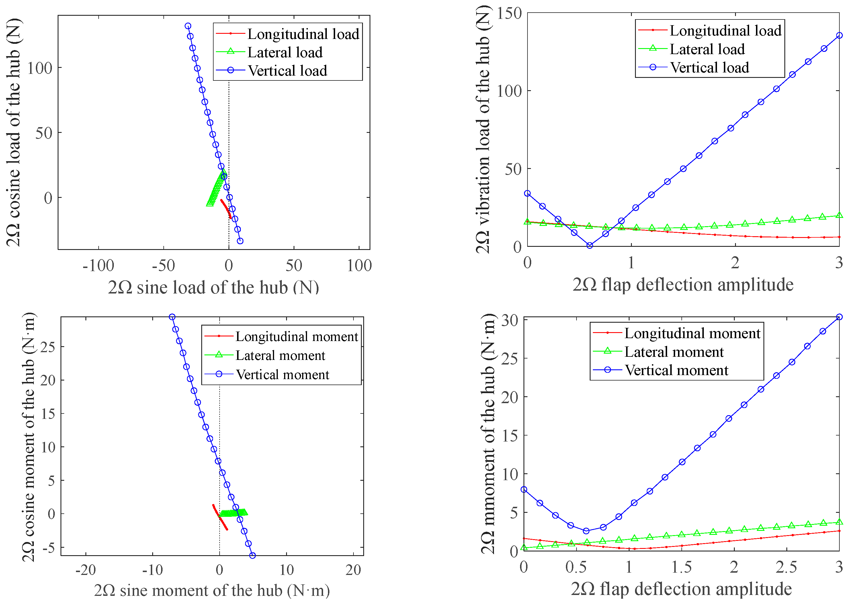
Figure 5 shows the effect of changes in the amplitude of higher-order flap deflection on the vibration load and moment of the hub. For the vibration load in three directions, the vertical vibration load is the most sensitive to the higher-order flap deflection and has the most serious non-controlled response. Thus, the higher-order flap deflection phase was selected to eliminate the vertical vibration load, as it can be seen that the polar curve obtained from the higher-order flap sweep can almost pass the theoretical optimal point. When the amplitude of higher-order flap deflection was 0.6°, the level of 2Ω vertical vibration of the ECR hub was about 0.6 N, which is 98% lower than that without control. Furthermore, the 2Ω vertical vibration of the hub varied linearly with the higher-order flap deflection amplitude. The 2Ω longitudinal vibration load of the hub achieved the optimal control when the amplitude of higher-order flap deflection reached 2.7°, the vibration level could be reduced by 62.5%. and the lateral vibration load could be reduced by 22% at most when the 2Ω flap deflection amplitude was 1.2°.
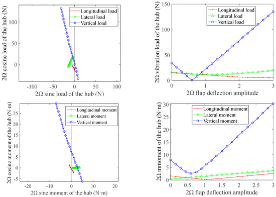
Figure 5.
The effect of change in the higher-order flap amplitude on the vibration load and moment of the hub.
For the 2Ω vibration moments, the vertical moment was the most sensitive to the higher-order flap deflection and could be reduced by 68% at most when the 2Ω flap deflection amplitude was 0.6°, and the 2Ω longitudinal moment could achieve 83% reduction when the flap deflection amplitude reached 1°. Meanwhile, the 2Ω lateral moment kept growing as the flap deflection amplitude increased, which indicates that it is necessary to adjust the phase of the higher-order flap deflection to reduce the 2Ω lateral vibration moment of the hub.
3.2.2. Phase Sweep of Higher-Order Harmonic Flap Control
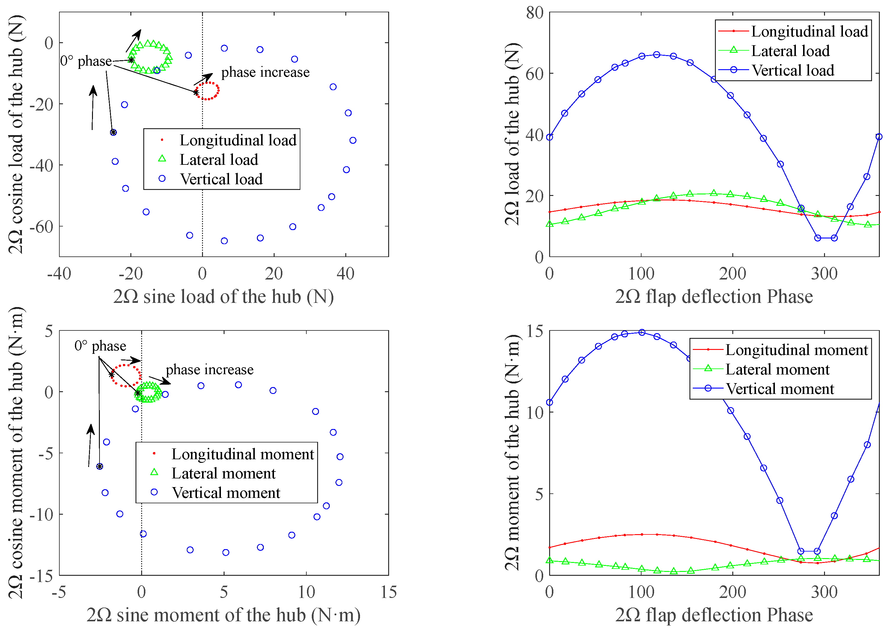
After completing the amplitude sweep of higher-order harmonic flap control, this section further investigates the effect of the higher-order flap deflection phase on the vibration load of the hub. The phase of the higher-order flap deflection swept for one cycle from 0° to 360° at an interval of 18°. When the higher-order flap deflection phase was swept, the amplitude of the higher-order flap deflection was chosen to be a constant of 0.6°, which is most conducive to the control of vertical vibration load. By plotting the polar diagram of the phase sweep of the higher-order flap deflection, the effect of the change in the amplitude of higher-order flap deflection motion on the 2Ω vibration component of the six-force factor of the hub was analyzed.
For a general linear multi-cyclic control system, when a phase sweep is performed for a control signal of a specific frequency, the polar diagram of the steady-state response of the linear system should be an ellipse. The lengths of the semi axes are and . By selecting appropriate amplitudes of the sweep signal, the ellipse can be made to pass exactly through the origin of the system, in which case the vibration of the system is minimized, and the phase at this point is optimal for system vibration control.
Figure 6 reflects the effect of the phase of the higher-order flap deflection on the 2Ω longitudinal vibration load of the hub. Similar to the results of amplitude sweep, the vertical vibration load and moment were more sensitive to the higher-order flap deflection than the other two directions, and the polar diagram of the steady-state response of the vibration load and moment is very close to an ellipse. The optimal phases of 2Ω flap deflection for the three-directional vibration load are 306°, 342°, and 288°, and the optimal phases of 2Ω flap deflection for the three-directional moment are 288°, 126°, and 288°.
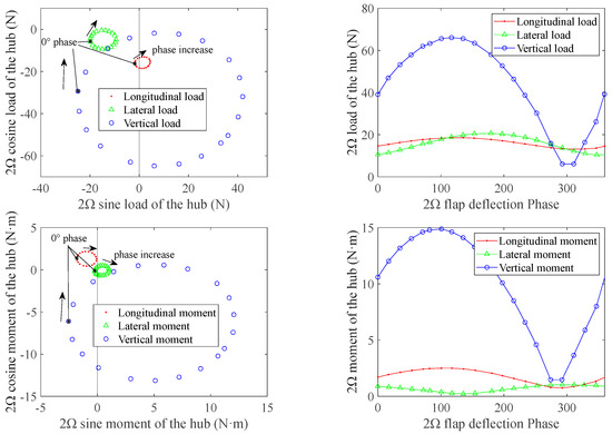
Figure 6.
The effect of change in the higher-order flap phase on the vibration load and moment of the hub.
According to the above results, under the wind tunnel trim conditions in this study, the 2Ω higher-order flap deflection at a phase of −50° had a positive effect on the reduction in all vibration components of the hub except lateral moment vibration. The 2Ω higher-order flap deflection not only generates an appropriate aerodynamic force to offset the original vertical load of the hub but also optimizes the aerodynamic load distribution on the disc. The 2Ω deflection motion of the trailing edge flaps causes the 2Ω pitch motion of the blade, which makes the blade generate four deflection peaks during one revolution, among which two are upward and the other two are downward, with the two deflection peaks of each direction separated by 180°. Through reasonable arrangement of the positions of these four peaks, the two downward deflection amplitudes are located at azimuths of 0° and 180° of the disc, which reduce the pitch of the advancing and retreating sides of the blade and increase the pitch angle of the front and rear sides of the blade through the aeroelastic effect, thereby unloading the aerodynamic loads on the left and right sides of the rotor and transferring them to the front and rear sides of the disc. Since the relative velocities of air on the front and rear sides of the disc are almost equal, the 2Ω deflection motion of the trailing edge flaps can weaken the effect of asymmetric aerodynamic loads and optimize the aerodynamic distribution on the disc, thereby reducing the vibration loads.
3.3. Effect of Higher-Order Harmonic Flap Control on the Main Control of ECR
The main task of the trailing edge flaps of the ECR is to use the aerodynamic moment caused by flap deflection to change the collective pitch and cyclic pitch of the blade to realize the main control of the rotor. On this basis, the superimposition of higher-order flap deflection changes the trim state of the ECR and increases the deflection range of the flaps, and the linearity of the aerodynamic force of the blade decreases as the airfoil’s angle of attack increases. In this section, the higher-order deflection motion of the trailing edge flaps is added to the ECR in the trim state. By changing the amplitude and phase of the higher-order flap deflection motion, the effects of different deflection motions of the trailing edge flaps on the collective pitch, cyclic pitch, rotor lift, and the longitudinal and lateral hub moments of the ECR in the trim state were investigated to obtain the characteristics and patterns of the effect of higher-order flap deflection on the main control of the ECR.
3.3.1. Amplitude Sweep of Higher-Order Harmonic Flap Control
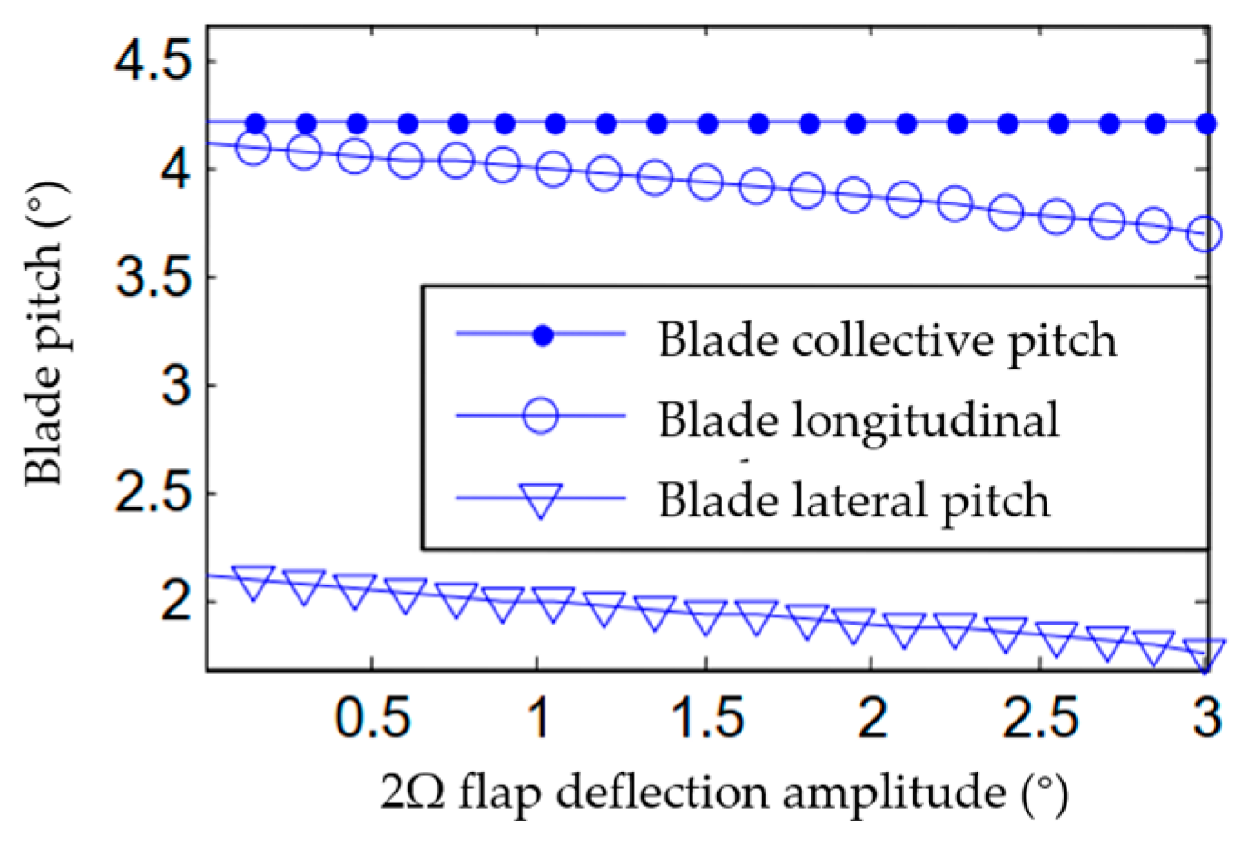
Based on the results given in the previous section, the optimal control phase of the vertical vibration load of the rotor, i.e., −50°, was selected as the phase of higher-order flap deflection, and the amplitude of higher-order flap deflection was increased from 0° to 3° to investigate the effect of the change in the amplitude of higher-order flap deflection on the trim state of the main control of the ECR. As shown in Figure 7, as the higher-order deflection amplitude of the trailing edge flaps increases, the collective pitch of the blade is barely affected, but the 1Ω pitch motion of the blade adjacent to 2Ω is greatly affected.
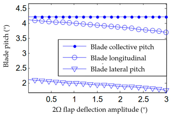
Figure 7.
The effect of change in the 2Ω flap amplitude on the blade pitch angle.
Due to the pitch change, the lift of the ECR and the tilt angle of the disc also changed after adding the higher-order flap deflection. The lift exhibits a complex change pattern but is always in a state of monotonically increasing. Figure 8a shows that as the 2Ω flap amplitude increases, the lift of the ECR increases by about 0.8%, which is probably due to the fact that the higher flap deflection with a phase of −50° reasonably distributes the load, and the reduced cyclic pitch of the blade decreases the deflection range of its collective pitch, so the same collective pitch can provide more lift. Furthermore, Figure 8b shows that the simultaneous reduction in the longitudinal and lateral cyclic pitches of the blade leads to a first-order flapping motion of the blade of about 0.45°, in which the forward tilt angle and the side chamfer of the blade increase by about 0.25° and 0.4°, respectively. Clearly, the higher-order harmonic flap motion has a certain effect on the main control of the ECR; the higher-order harmonic flap motion weakens the control effect of the cyclic pitch of the flaps and simultaneously causes some additional lift of the rotor; and the higher the amplitude of higher-order harmonic flap motion, the greater the effect on the trim of the ECR.
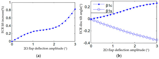
Figure 8.
The effect of change in the 2Ω flap amplitude on the lift and disc tilt angle of the ECR. (a) Lift. (b) Disc tilt angle.
3.3.2. Phase Sweep of Higher-Order Harmonic Flap Control
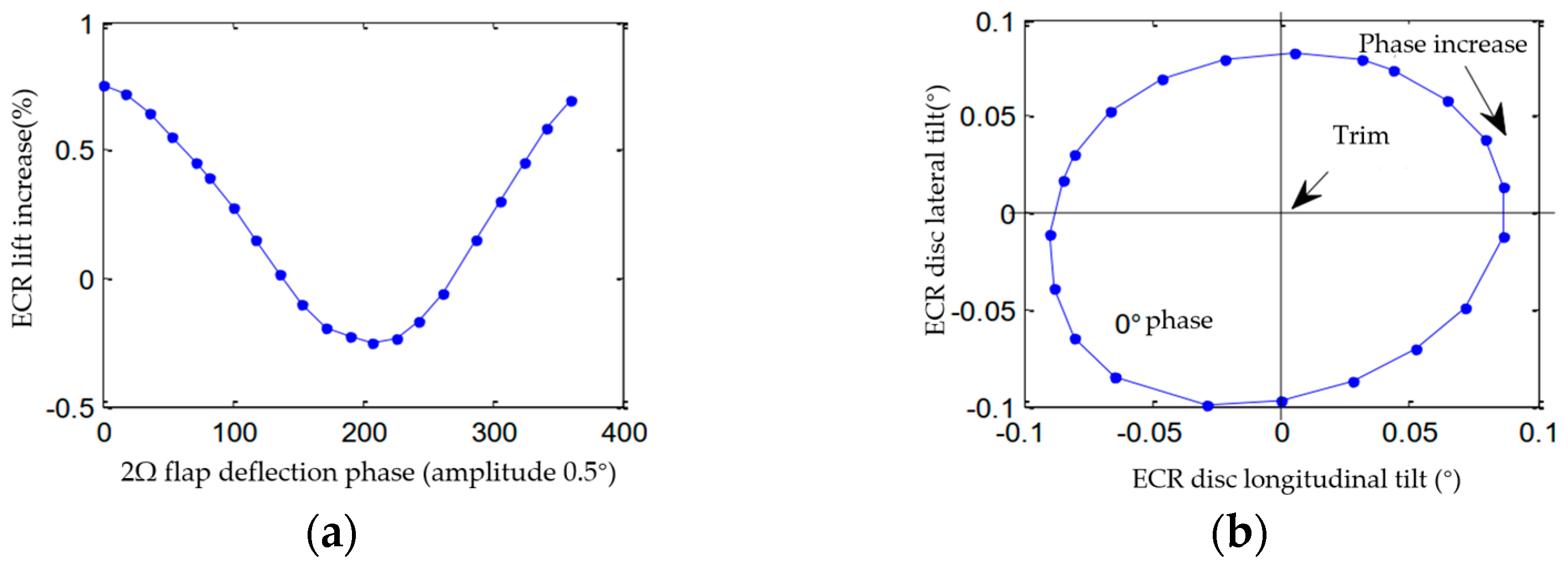
Considering changes in the flight state of the helicopter, the phase of the higher-order deflection of the trailing edge flaps used for ECR vibration reduction may change. Therefore, this section also investigates the effect of changes in the phase of the higher-order deflection of the trailing edge flaps on the main control of the ECR by sweeping the phase of the higher-order deflection of the trailing edge flaps. According to the results in the previous section, the vertical vibration of the hub could be greatly reduced when the higher-order flap deflection had an amplitude of 0.5°. Therefore, the amplitude of the higher-order deflection of the trailing edge flaps was set to 0.5° in this section to investigate the patterns of changes in the collective pitch, cyclic pitch, rotor lift, and disc tilt angle of the ECR when the trailing edge flaps deflect with different phases.
Figure 9 shows that under a higher-order flap deflection of 0.5°, the change in the collective pitch of the blade remains small with the change in the phase of the higher-order flap deflection. When the phase of the higher-order flap deflection exceeds 180°, the collective pitch of the ECR only increases by 0.05°, whereas the longitudinal and lateral cyclic pitches of the blade change greatly by about 0.25°. The longitudinal cyclic pitch of the blade reached its maximum when the phase of higher-order flap deflection was 180°, while the pattern of change in the lateral cyclic pitch of the blade was 90° out of phase with the pattern of change in the longitudinal cyclic pitch of the blade.
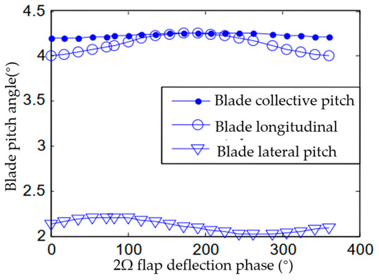
Figure 9.
The effect of change in the 2Ω flap phase on the pitch.
Figure 10a shows that when the phase of the higher-order flap deflections is 180°, the lift of the rotor decreases and the collective pitch of the blade increases. This is because the large pitch of the retreating blade along with the small horizontal component of the airflow velocity in this case leads to a further increase in its angle of attack. Due to the nonlinear characteristics of the airfoil at a large angle of attack, the increase in the pitch of the retreating blade fails to compensate for the lift loss caused by the decrease in front and rear pitches, thereby reducing the total lift of the rotor. The disc tilt angle of the ECR is also affected. As shown in Figure 10b, under a 0.5° 2Ω flap deflection, the disc tilts to the left front at the beginning, and with the increase in higher-order flap deflection, the disc tilt angle rotates around the equilibrium position in a clockwise direction, and the disc tilt angles caused by the higher-order flap deflection with different phases are roughly equal (about 0.1°).
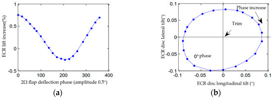
Figure 10.
The effect of change in the 2Ω flap phase on the lift and disc tilt angle of the ECR. (a) Lift. (b) Disc tilt angle.
4. Conclusions
In this study, an aeroelastic computational model of an ECR was established using Hamilton’s principle and an unsteady aerodynamic flap model. On this basis, the effect of higher-order harmonic flap control on the vibration load of the ECR was investigated. By sweeping the amplitude and phase of the 2Ω higher-order flap deflection, the effect of 2Ω higher-order harmonic flap control on the 2Ω vibration load of the example ECR was explored, and the effect of the higher-order harmonic flap control on the main control of the ECR was analyzed in terms of the lift, pitch, and disc tilt angle of the example ECR. The specific conclusions of this study are as follows:
- (1)
- The 2Ω higher-order flap deflection has the most significant control effect on the 2Ω vertical vibration load of the hub. The control patterns of the six vibration components of the hub are similar, except for that of the lateral moment vibration of the hub. In the wind tunnel trim state investigated in this study, the 2Ω vibration load of the hub could achieve the best control effect when the 2Ω higher-order deflection of the trailing edge flaps had a phase of −50° and an amplitude of 0.6°.
- (2)
- The higher-order flap deflection is coupled with the main control of the ECR and destroys the original equilibrium state of the ECR. Therefore, it is necessary to perform coupling trim through the main control/active vibration coupling control to improve the accuracy of the primary control and active vibration control of the ECR.
Author Contributions
Methodology, K.L. and J.M.; investigation, T.S.; writing—original draft preparation, K.L. and T.S.; writing—review and editing, T.S.; funding acquisition, T.S. and Z.Z. All authors have read and agreed to the published version of the manuscript.
Funding
This research was funded by the Opening Foundation of Rotor Aerodynamics Key Laboratory, grant number RAL20200301, and the Jiangxi 03 and 5G project, grant number 20212ABC03A03.
Institutional Review Board Statement
Not applicable.
Informed Consent Statement
Not applicable.
Data Availability Statement
Not applicable.
Acknowledgments
This work was supported by the Opening Foundation of Rotor Aerodynamics Key Laboratory (RAL20200301) and the Jiangxi 03 and 5G project (20212ABC03A03).
Conflicts of Interest
The authors declare no conflict of interest.
References
- Su, T.; Lu, Y.; Ma, J.; Guan, S. Aerodynamic characteristics analysis of electrically controlled rotor based on viscous vortex particle method. Aerosp. Sci. Technol. 2020, 97, 105645. [Google Scholar] [CrossRef]
- Ormiston, R.A. Aeroelastic considerations for rotorcraft primary control with on-blade elevons. In Proceedings of the 57th American Helicopter Society Annual Forum, Washington, DC, USA, 9–11 May 2001. [Google Scholar]
- Su, T.; Lu, Y.; Ma, J.; Guan, S. Electrically controlled rotor blade vortex interaction airloads and noise analysis using viscous vortex particle method. Shock Vib. 2019, 2019, 9678970. [Google Scholar] [CrossRef]
- Li, K.; Su, T.; Lu, Y.; Zhao, Q. Nonharmonic control of the blade-vortex interaction noise of electrically controlled rotor. Int. J. Aerosp. Eng. 2022, 2022, 5353681. [Google Scholar] [CrossRef]
- Shen, J.; Chopra, I. A parametric design study for a swashplateless helicopter rotor with trailing edge flaps. J. Am. Helicopter Soc. 2004, 49, 43–53. [Google Scholar] [CrossRef]
- Lu, Y.; Wang, C. Active control for performance enhancement of electrically controlled rotor. Chin. J. Aeronaut. 2015, 28, 1494–1502. [Google Scholar] [CrossRef]
- Johnson, W. Rotorcraft Aeromechanics, 1st ed.; Cambridge University Press: New York, NY, USA, 2013; pp. 717–720. [Google Scholar]
- Shaw, J.; Albion, N.; Hanker, E.J.; Teal, R.S. Higher harmonic control: Wind tunnel demonstration of fully effective vibratory hub force suppression. J. Am. Helicopter Soc. 1989, 34, 14–25. [Google Scholar] [CrossRef]
- Nguyen, K.; Chopra, I. Application of higher harmonic control to rotors operating at high speed and thrust. J. Am. Helicopter Soc. 1990, 35, 78–89. [Google Scholar] [CrossRef]
- Brooks, T.F.; Booth, E.R. The effects of higher harmonic control on blade-vortex interaction noise and vibration. J. Am. Helicopter Soc. 1993, 38, 45–55. [Google Scholar]
- Morbitzer, D.; Arnold, T.P.; Mueller, M. Vibration and noise reduction through individual blade control-experimental and theoretical results. In Proceedings of the 24th European Rotorcraft Forum, Marseille, France, 15–17 September 1998. [Google Scholar]
- Roth, D. Advanced vibration reduction by IBC technology. In Proceedings of the 30th European Rotorcraft Forum, Marseille, France, 14–16 September 2004. [Google Scholar]
- Norman, T.R.; Theodore, C.; Shinoda, P.; Fuerst, D.; Arnold, T.P.; Makinen, S.; Lorber, P.; O’Neill, J. Full-scale wind tunnel test of a UH-60 individual blade control system for performance improvement and vibration, loads, and noise control. In Proceedings of the 65th American Helicopter Society Annual Forum, Grapevine, TX, USA, 27–29 May 2009. [Google Scholar]
- Fulton, M.V.; Ormiston, R.A. Small-scale rotor experiments with on-blade elevons to reduce blade vibratory loads in forward flight. In Proceedings of the 54th American Helicopter Society Annual Forum, Washington, DC, USA, 20–22 May 1998. [Google Scholar]
- Roget, B.; Chopra, I. Closed-loop test of a rotor with individually controlled trailing-edge flaps for vibration reduction. J. Am. Helicopter Soc. 2010, 55, 12009. [Google Scholar] [CrossRef]
- Straub, F.K.; Anand, V.R.; Lau, B.H. Wind tunnel test of the SMART active flap rotor. J. Am. Helicopter Soc. 2018, 63, 1–16. [Google Scholar] [CrossRef]
- Shen, J.W.; Chopra, I. Swashplateless helicopter rotor with trailing edge flaps. J. Aircr. 2005, 41, 208–214. [Google Scholar] [CrossRef]
- Leishman, J.G.; Beddoes, T.S. A generalized method for unsteady airfoil behavior and dynamic stall using the indicial method. In Proceedings of the 42th American Helicopter Society Annual Forum, Washington, DC, USA, 2–4 June 1986. [Google Scholar]
- Hariharan, N.; Leishman, J.G. Unsteady aerodynamics of a flapped airfoil in subsonic flow by indicial concepts. In Proceedings of the 36th AIAA/ASME/ASCE/AHS/ASC Structures, Structural Dynamics, and Materials Conference, New Orleans, LA, USA, 10–12 April 1995. [Google Scholar]


Disclaimer/Publisher’s Note: The statements, opinions and data contained in all publications are solely those of the individual author(s) and contributor(s) and not of MDPI and/or the editor(s). MDPI and/or the editor(s) disclaim responsibility for any injury to people or property resulting from any ideas, methods, instructions or products referred to in the content. |
© 2023 by the authors. Licensee MDPI, Basel, Switzerland. This article is an open access article distributed under the terms and conditions of the Creative Commons Attribution (CC BY) license (https://creativecommons.org/licenses/by/4.0/).