Article

Nonlinear Dynamics and Vibration Localization of Shrouded Blisk with Contact and Friction Effects

1
Department of Engineering Mechanics, Dalian University of Technology, Dalian 116024, China
2
State Key Laboratory of Structural Analysis for Industrial Equipment, Dalian 116024, China
*
Author to whom correspondence should be addressed.
Machines 2023, 11(2), 238; https://doi.org/10.3390/machines11020238
Submission received: 21 December 2022 / Revised: 26 January 2023 / Accepted: 31 January 2023 / Published: 6 February 2023
(This article belongs to the Special Issue Dynamic Stability Analysis of Aerospace Structures)

Abstract

:
Shrouds have been widely used to reduce the level of excessive vibration of blisks. However, complicated nonlinear motion can be induced by the contact and friction between shrouds. Even worse, harmful localization of vibration can be encountered due to nonsmooth behaviour at the shroud contact interfaces in the tuned disk. In this paper, the nonlinear dynamics and localization of vibration of a shrouded blisk are studied considering the spin softening. The continuous parametric model of a shrouded blisk is established, and the transition boundaries between different status (i.e., stick, slip and separation) of shrouds are determined based on the Coulomb friction model. The steady-state responses of the blisk are analysed using variable rotation speed, and the primary resonance, beat and quasi-periodic vibration are presented in connection with the non-smooth behaviour of contact. A particular type of vibration localization initiated by the contact and friction effect of the shrouds in the form of asymmetric vibration in the tuned blisk is discovered. It is found that the blades-disk coupling has strong influences on the level of the localization. The effects of the contact stiffness and localization on the blade vibration are demonstrated through the change in the powers of the blade motions.

1. Introduction

High-speed rotating disks are commonly used in gas turbine and steam turbines that operate in aeroengines and power generators. Under various circumstances, excessive vibration takes place due to the action of large aerodynamic and mechanical forces, which may lead to the eventual fatigue of the blades [1]. Shrouds have been widely used by steam turbines developers to dissipate energy and reduce stress of the blades, so as to improve the life of the blade [2]. However, additional effect of structural coupling can be introduced to adjacent shrouds through contact and friction on the mating interfaces, which leads to nonlinear characteristics such as non-smoothness and hence makes accurate prediction of vibration response of the disk difficult to achieve.
Extensive research has been devoted to the modeling of shrouded blisks including structurally modeling of blisks and the corresponding contacts of adjacent shrouds. A tuned, cyclically symmetrical blisk can be simplified as a single bladed sector [3], integrally shrouded group blade [4,5] or blade packet [6]. To admit the dynamical characteristics of the disk, Petrov [7,8] used the surface elements to simulate the contact between adjacent shrouds of the full structure. Beam-like blades and a rigid disk were coupled to a continuous parameter model of a blisk by Shadmani [9]. As for the contact model, various methods have been proposed to characterize the impact and friction of shrouds. In early publications, Sgn-contact, macro-slip and micro-slip models were proposed to simulate the lumped mass model of shrouds by Iwan [10], Griffin [11] and Menq [12], respectively. In subsequent studies, Cigeroglu et al. [13] put forward a two-dimensional distributed parameter microslip friction model considering the change in normal pressure caused by motion in normal direction. Yang and Menq [14] proposed a three-dimensional contact model to predicted the resonant response of structures having 3D frictional constraint.
It was known previously that collision and friction are in their nature nonlinear or, at least, piecewise linear, due to the change in relative velocity of vibrating bodies on their mating interfaces [15,16], and are attributable to complicated dynamic behaviors such as bifurcation, chaos and switch of stability [17]. For a slender structure undergoing impact, Liu et al. [18] proposed a model of fractal geometry and analyzed the effect of the surface roughness and normal loads on dynamic responses of blades, Li et al. [19] established a macro-slip friction model of the contact interfaces at the root of the beam with a dovetail tenon to characterize the friction on the beam. As for the friction between shrouds, He et al. [20] established an integrally shrouded blades considering impact and friction between adjacent shrouds, and reported multi-periodic, quasi-periodic and chaotic vibration of blade due to nonsmooth behaviour at the shroud contact surfaces. As far as the nonlinear vibration of a full blisk is concerned, progresses have been achieved in veering and merging analysis [21,22], localization of vibration [23,24], robust analysis [25] and parametric sensitivity [26]. In addition, some scholars study the contact and friction of blades based on the micro-slip contact model, Pesaresi et al. [27] presented a new modelling approach for underplatform dampers and evaluated against the experimental data of a recently-developed test rig, Chen et al. [28] proposed a new contact slip modeling method which can preserve the pressure distribution of the joint’s contact surface to capture the micro-slip phenomenon.
As for the localization of vibration, most of the existing researches were carried out under the assumption that the vibration localization is caused by the mistuning of blisks [29,30,31,32]. A few publications were dedicated to the vibration localization of cyclically symmetric structures with nonlinearities. Vakakis et al. [33,34] found that nonlinear mode localization can occur in perfectly symmetric nonlinear periodic systems, and the only prerequisite for its existence is weak coupling between subsystems. Based on the researches of Vakakis, Grolet and Thouverez [35] computed the free and forced response of a system with cyclic symmetry under geometric nonlinearity, and found that some of the bifurcated solutions correspond to localized nonlinear modes in the branching point bifurcation of the system. In addition, Fontanela et al. [36] developed a fully numerical approach to compute quasi-periodic vibrations bifurcating and localized oscillations from nonlinear periodic states in cyclic and symmetric structures.
Despite many existent publications regarding vibration of rotating shrouded blisks, there still lacks research that focused on interactions of adjacent shrouds through contact and friction, and their possible contribution to the localization of vibration of the disk. Such localization is usually accompanied with harmful concentration of vibration energy in one or a few blades, and is considered one of the major inducements to the onset of fatigue failure.
In this paper, the nonlinear dynamics and the localization of vibration of a tuned shrouded blisk that has short blades of small installation angles are investigated considering the effect of contact and friction between adjacent shrouds. The paper is organized as follows: Firstly, the continuous parametric model of the whole shrouded blisk is presented where the interaction between shrouds is modeled using linear spring and velocity-dependent force. The transition of contact states (i.e., stick, slip and separation) of adjacent shrouds are determined. Secondly, the vibration characteristic of the blades such as primary resonance, beat phenomenon and quasi-periodic vibration are analysed with the increase rotation speed. Finally, a particular type of vibration localization due to nonsmooth behaviour at the shroud contact interfaces is discovered in the tuned blisk, the effects of the blades-disk coupling on the level of localization are illustrated, and the effects of the normal contact stiffness and the localization of vibration on the blade vibration are demonstrated.

2. Dynamics Modelling of Shrouded Blisk

As shown in Figure 1, a rotating shrouded blisk with short blades of small installation angles is concerned in this study, where Ω represents rotation speed. Structurally, the blisk is comprised of a disk and multiple identical blades that crowned with shrouds.
One may notice that for such a blisk, the dynamical modeling can be simplified as an in-plane dynamic model for the following reasons:
  • The torsion of the blade body in the spanwise direction is generally small in view of turbine design for short blades. When short blades are concerned, the change in the circumferential velocity in the blade’s spanwise direction can be assumed small. Consequently, the directions of the relative velocity of the fluid to the blade vary limitedly in the same direction, and thus the torsion angle is idealized to be small for short blades.
  • The bending rigidity of the blade is generally large compared with a long blade, and the modal couplings between in-plane and out-of-plane motions due to geometrically nonlinearity is weak enough to be ignored.
  • When the installation angle is small, the aerodynamic force normal to the blade surface stands mainly in the plane of blisk rotation [20], meaning the in-plane component of the force is much larger than its out-of-plane counterpart. Under the same assumption of small installation angle, the principal axes of the blade cross-section are arranged in such a way that the bending rigidity in the out-of-plane direction overwhelms that in the in-plane directions. Hence, it is reasonable not to consider the out-of-plane motions in the present study owing to the small load and large bending rigidity in the out-of-plane.

2.1. Dynamic Modeling

Figure 2 depicts the model of the shrouded blisk, where two cartesian frames are established to express the blade motions. Frame XYZ is inertial cartesian coordinate, where X-axis is parallel to the ground and Z-axis is parallel to the normal of the disk. The other frame, x i y i z i , is a body coordinate fixed at the barycentre of the i-th blade root, and rotates synchronously with the blade. Let (I, J, K) and ( i i , j i , k i ) be the unit base vectors of the two frames, respectively bounded by the following transformation
[ i i j i k i ] = [ cos θ i sin θ i 0 sin θ i cos θ i 0 0 0 1 ] [ I J K ]
Two degrees of freedom, x d and y d are adopted to locate the instantaneous center of disk in the X- and Y- directions, respectively. The contribution of the shaft to the disk is described by stiffness coefficients k x and k y , and viscous damping coefficients c x and c y , respectively. d r is the radius of the disk. The angular orientation of the i-th blade is
θ i = Ω t + 2 π n ( i 1 )
where n is the total number of blades. In Figure 2b, α is the tilt angle of shrouds and L is the length of the blade. δ s and k s are the gap and the normal contact stiffness between adjacent shrouds. N s , i , F s , i and Q i are forces of normal contact, friction and aerodynamic [20]. N s , i and F s , i are perpendicular and parallel to the contact interfaces, respectively. Q i is parallel to the negative direction of the y i -axis of the i-th blade.
Q i = Q 0 sin ( λ Ω t + φ i )
where Q 0 is the forcing amplitude, λ the number of inlet vanes in the upstream of the blades [20] and φ i = i π is the phase of Q i .
The position of the i-th blade R b , i , shroud R s , i and barycenter of the disk R d at the current moment are
R b , i = x d I + y d J + d r i i + ( x i + u i ) i i + v i j i , R s , i = R b , i δ ( x i L ) , R d = x d I + y d J
where u i and v i are spanwise and flapwise displacements of the blade. δ ( x i L ) is the Dirac-delta function.
As for the contact and friction forces between adjacent shrouds, it is noticed that the actual friction between the adjacent shrouds lie in a 2D surface defined in the three-dimensional space. Nonetheless, it is appropriate to model the shroud as a concentrated mass since it is considerably smaller than the blade. With this modeling, the friction force on the contact surface can be vectorially decomposed into two components in- and out-of- the blisk’s rotation plane. However, the out-of-plane component of the friction force can be effectively ignored since the out-of-plane movement has been assumed negligible in the first place, and hence ideally there will be neither relative movement nor trends of relative movement between two adjacent shrouds. Further, the state of contact between two adjacent shrouds during operation one of the three: stick, slip and separation, depending on the relative motion of the shrouds. In this particular scenario, the normal distance between the shrouds is expressed as
d i = ( u i 1 u i ) cos α + ( v i 1 v i δ s ) sin α
Hence, the normal force imposed on the right side of the i-th shroud is
N s , i = { k s d i d i > 0 0 d i 0
For the friction on the solid, dry contact surface, a velocity-dependent model [37] is adopted where friction asymptotically decreases as the relative velocity increases, as
μ ( s r , i ) = μ m + ( μ s μ m ) e β | s r , i |
where μ m and μ s are coefficients of minimum kinetic friction and maximum static friction. β is the tuning parameter. s r , i is the relative velocity aligning with the contact surfaces of the i-th and the (i-1)-th shrouds, which can be expressed as
s r , i = ( u ˙ i 1 u ˙ i ) sin α + ( v ˙ i 1 v ˙ i ) cos α
Thus, F s , i governed by the stick-slip model can be written as
F s , i = { μ ( s r , i ) N s , i sgn ( s r , i ) s r , i 0 μ s N s , i F s , i μ s N s , i s r , i = 0

2.2. Governing Equations

The governing equations of the shrouded blisk can be derived through the Hamilton’s principle. For the spanwise direction, one has
ρ l [ u ¨ i + x ¨ d cos θ i + y ¨ d sin θ i 2 Ω v ˙ i Ω 2 u i Ω 2 ( x i + d r ) ] ( E A u i ) + c u u ˙ i + m s [ u ¨ i + x ¨ d cos θ i + y ¨ d sin θ i 2 Ω v ˙ i Ω 2 u i Ω 2 ( x i + d r ) ] δ ( x i L ) = ( N s , i + 1 cos α + F s , i + 1 sin α + N s , i cos α F s , i sin α ) δ ( x i L )
For the flapwise direction, the equation becomes
ρ l ( v ¨ i x ¨ d sin θ i + y ¨ d cos θ i + 2 Ω u ˙ i Ω 2 v i ) + ( E I v ) + c v v ˙ i + m s ( v ¨ i x ¨ d sin θ i + y ¨ d cos θ i + 2 Ω u ˙ i Ω 2 v i ) δ ( x i L ) = ( Q i N s , i + 1 sin α F s , i + 1 cos α + N s , i sin α + F s , i cos α ) δ ( x i L )
One the other hand, the equations of motion for the disk are
i = 1 n ρ l [ x ¨ d + u ¨ i cos θ i v ¨ i sin θ i 2 Ω u ˙ i sin θ i 2 Ω v ˙ i cos θ i + Ω 2 v i sin θ i Ω 2 u i cos θ i Ω 2 ( x i + d r ) cos θ i ] + i = 1 n m s [ x ¨ d + u ¨ i cos θ i v ¨ i sin θ i 2 Ω u ˙ i sin θ i 2 Ω v ˙ i cos θ i + Ω 2 v i sin θ i Ω 2 u i cos θ i Ω 2 ( x i + d r ) cos θ i ] δ ( x i L ) + ( m d x ¨ d + c x x ˙ d + k x x d ) δ ( x i 0 ) = 0
and
i = 1 n ρ l [ y ¨ d + u ¨ i sin θ i 2 Ω v ˙ i sin θ i + v ¨ i cos θ i + 2 Ω u ˙ i cos θ i Ω 2 v i cos θ i Ω 2 u i sin θ i Ω 2 ( x i + d r ) sin θ i ] + i = 1 n m s [ y ¨ d + u ¨ i sin θ i 2 Ω v ˙ i sin θ i + v ¨ i cos θ i + 2 Ω u ˙ i cos θ i Ω 2 v i cos θ i Ω 2 u i sin θ i Ω 2 ( x i + d r ) sin θ i ] δ ( x i L ) + ( m d y ¨ d + c y y ˙ d + k y y d ) δ ( x i 0 ) = 0
where ρ l is the linear mass density of the blades and m s the mass of the shrouds. EA and EI stand for tensile and bending stiffness of the blade, respectively. c u and c v are viscous damping coefficients in the spanwise and flapwise directions, respectively.
In the followings, the Galerkin’s method is adopted to decompose the spanwise and flapwise displacements in the modal space, as
u i ( x , t ) = j = 1 Ψ j ( x ) p j i ( t ) , v i ( x , t ) = j = 1 Φ j ( x ) q j i ( t )
where Ψ j ( x ) and Φ j ( x ) are the j-th mode shapes of cantilever beam in the spanwise and flapwise directions, respectively [38]. p j i ( t ) and q j i ( t ) are the j-th modal coordinates of the i-th blade, respectively. Considering only the first mode in both two directions, Equations (10)–(13) are reduced
m i , i p ¨ i + m i , 2 n + 1 x ¨ d + m i , 2 n + 2 y ¨ d + c i , i p ˙ i + g i , n + i q ˙ i + k i , i p i = a i N s , i + 1 cos α + F s , i + 1 sin α + N s , i cos α F s , i sin α , i = 1 , 2 , , n ,
m n + i , n + i q ¨ i + m n + i , 2 n + 1 x ¨ d + m n + i , 2 n + 2 y ¨ d + g n + i , i p ˙ i + c n + i , n + i q ˙ i + k n + i , n + i q i = Q i N s , i + 1 sin α F s , i + 1 cos α + N s , i sin α + F s , i cos α , i = 1 , 2 , , n ,
i = 1 n ( m 2 n + 1 , i p ¨ i + m 2 n + 1 , n + i q ¨ i ) + m 2 n + 1 , 2 n + 1 x ¨ d + i = 1 n ( g 2 n + 1 , i p ˙ i + g 2 n + 1 , n + i q ˙ i ) + c 2 n + 1 , 2 n + 1 x ˙ d + i = 1 n ( k 2 n + 1 , i p i + k 2 n + 1 , n + i q i ) + k 2 n + 1 , 2 n + 1 x d = a 2 n + 1 ,
i = 1 n ( m 2 n + 2 , i p ¨ i + m 2 n + 2 , n + i q ¨ i ) + m 2 n + 2 , 2 n + 2 y ¨ d + i = 1 n ( g 2 n + 2 , i p ˙ i + g 2 n + 2 , n + i q ˙ i ) + c 2 n + 2 , 2 n + 2 y ˙ d + i = 1 n ( k 2 n + 2 , i p i + k 2 n + 2 , n + i q i ) + k 2 n + 2 , 2 n + 2 y d = a 2 n + 2
where notations m, c, g, k and a are defined in Equations (A1)–(A5), Appendix B.
The non-dimensional forms of Equations (15)–(18) can be rewritten by introducing the following variables:
p ¯ i = p i δ s , q ¯ i = q i δ s , x ¯ d = x d δ s , y ¯ d = y d δ s , ω i 2 = k i , i m i , i , ω n + i 2 = k n + i , n + i m n + i , n + i , ω 2 n + 1 2 = k 2 n + 1 m 2 n + 1 , ω 2 n + 2 2 = k 2 n + 2 m 2 n + 2 , τ q = ω n + i t , ( ) = d ( ) d τ q , a ¯ i = a i ω n + i 2 δ s m i , i , k ¯ s = k s k i , i , Q ¯ 0 = Q 0 ω n + i 2 δ s m n + i , n + i
Moreover, d i , N s , i and F s , i can be rewritten as
d ¯ i = Ψ ( L ) ( p ¯ i 1 p ¯ i ) cos α + [ Φ ( L ) ( q ¯ i 1 q ¯ i ) 1 ] sin α
N ¯ s , i = { k ¯ s d ¯ i d ¯ i > 0 0 d ¯ i 0
F ¯ s , i = { μ ( s r , i ) N ¯ s , i sgn ( s r , i ) s r , i 0 μ s N ¯ s , i F ¯ s , i μ s N ¯ s , i s r , i = 0
Using Equation (19), the non-dimensional form of the governing equations are
p ¯ * * i + m ¯ i , 2 n + 1 x ¯ d + m ¯ i , 2 n + 2 y ¯ d + c ¯ i , i p ¯ i + g ¯ i , n + i q ¯ i + ω ¯ i , i 2 p ¯ i = a ¯ i + m ¯ q p ( N ¯ s , i + 1 cos α + F ¯ s , i + 1 sin α + N ¯ s , i cos α F ¯ s , i sin α ) , i = 1 , 2 , , n
q ¯ i + m ¯ n + i , 2 n + 1 x ¯ d + m ¯ n + i , 2 n + 2 y ¯ d + g ¯ n + i , i p ¯ i + c ¯ n + i , n + i q ¯ i + q ¯ i = Q ¯ i N ¯ s , i + 1 sin α F ¯ s , i + 1 cos α + N ¯ s , i sin α + F ¯ s , i cos α , i = 1 , 2 , , n
x ¯ d + i = 1 n ( m ¯ 2 n + 1 , i p ¯ i + m ¯ 2 n + 1 , n + i q ¯ i ) + i = 1 n ( g ¯ 2 n + 1 , i p ¯ i + g ¯ 2 n + 1 , n + i q ¯ i ) + c ¯ 2 n + 1 , 2 n + 1 x ¯ d + i = 1 n ( k ¯ 2 n + 1 , i p ¯ i + k ¯ 2 n + 1 , n + i q ¯ i ) + ω ¯ 2 n + 1 2 x ¯ d = a ¯ 2 n + 1
y ¯ d + i = 1 n ( m ¯ 2 n + 2 , i p ¯ i + m ¯ 2 n + 2 , n + i q ¯ i ) + i = 1 n ( g ¯ 2 n + 2 , i p ¯ i + g ¯ 2 n + 2 , n + i q ¯ i ) + c ¯ 2 n + 2 , 2 n + 2 y ¯ d + i = 1 n ( k ¯ 2 n + 2 , i p i + k ¯ 2 n + 2 , n + i q i ) + ω ¯ 2 n + 2 2 y ¯ d = a ¯ 2 n + 2
The coefficients of Equations (23)–(26) are provided in Equations (A6)–(A9), Appendix B. A numerical simulation method implementing the Runge-Kutta method with variable steps is developed using MATLAB to solve the equations of motion of the shrouded blades in this study considering the nonsmooth contact and friction behavior. Given the significance of the contact behavior between adjacent shrouds on the blade dynamics, the bisection method is used to capture the precise times where the contact switches from one state to another in Appendix D. The transition of the contact states (i.e., stick, slip and separation) of adjacent shrouds and corresponding friction forces are provided in Appendix C.

3. Nonlinear Dynamics and Vibration Localization of Shrouded Blisk

This section includes the results of nonlinear dynamics study and vibration localization analysis of a shrouded, tuned blisk. The shrouded blisk with twelve blades is used for numerical investigation. The main parameters of the shrouded blisk [20,39] are shown in Table 1.
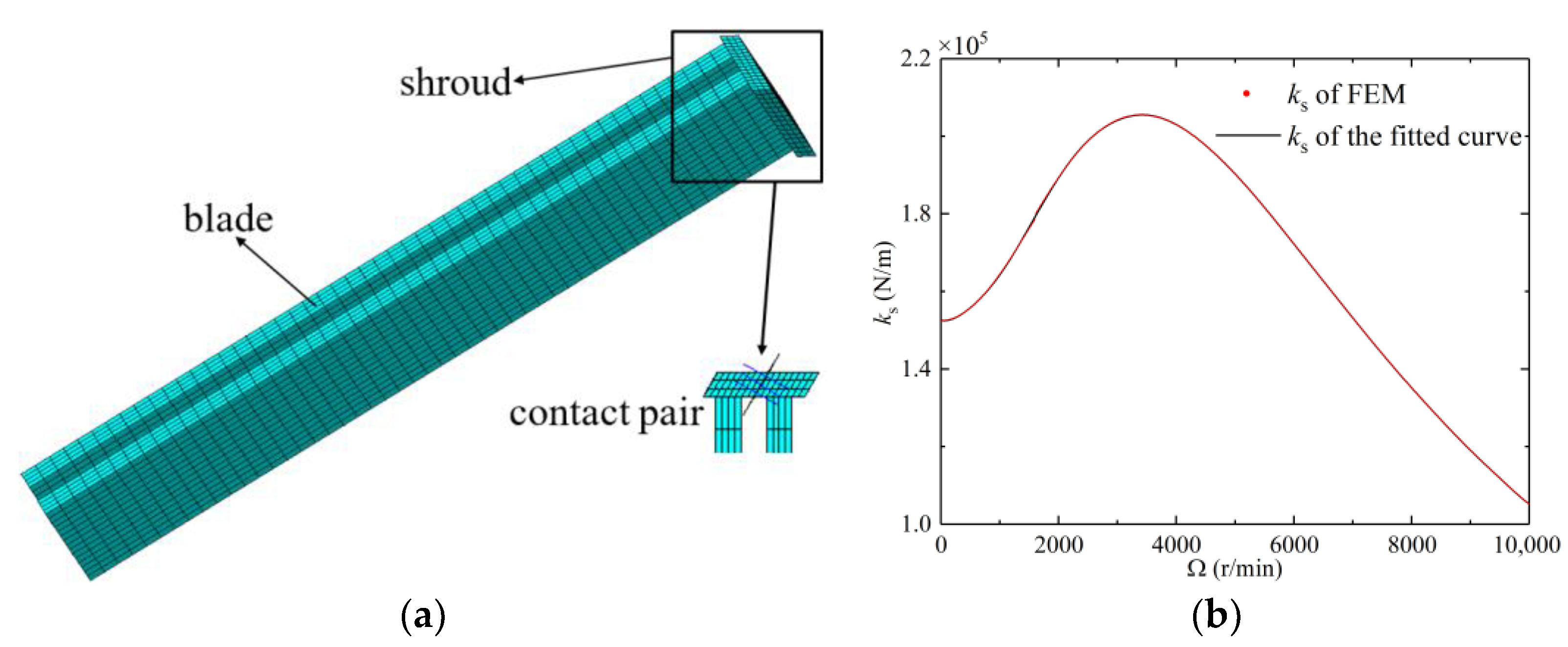
A finite element analysis containing two shrouded blades was carried out using ANSYS software to determine the normal contact stiffness ( k s , caused by the elastic deformation of the shroud) [5] at various rotation speed in this paper. As shown in Figure 3a, contact pair was used to simulate the connecting force between adjacent shrouds, the solid185-type elements were used to model the structural parts of the blades and shrouds. The parameters of the model are presented in Appendix E. Then, the contact stiffness was calculated based on the elastic deformations of the shrouds with respect to the reaction forces of the blades in the normal direction of the shroud. Afterwards, the contact stiffness was fitted to generate k s as a function of Ω , which is depicted in Figure 3b.
The vibration response can be solved once the normal contact stiffness determined. The steady-state responses with different rotation speeds are illustrated. Then, the localization of vibration due to the contact and friction of shrouds is studied.

3.1. Steady-State Response, Primary Resonance and Beat

The rotation of the disk creates centrifugal force and subsequently the effect of spin softening through which the blade’s axial stiffness is reduced, as well as changes the state of contact between adjacent shrouds as shown in Figure 3b. In the following, Equations (23)–(26) are solved with various rotation speeds to demonstrate how steady-state response is affected by these effects. Since the disk is structurally tuned, the response will be presented hereafter with only one sector including the first shrouded blade (i.e., i = 1 in Figure 2b). To facilitate the discussion in next subsections, two forcing parameters are introduced to represent the “net” contact and friction:
N 1 = N ¯ s , 1 N ¯ s , 2 ,   F 1 = F ¯ s , 1 F ¯ s , 2 .
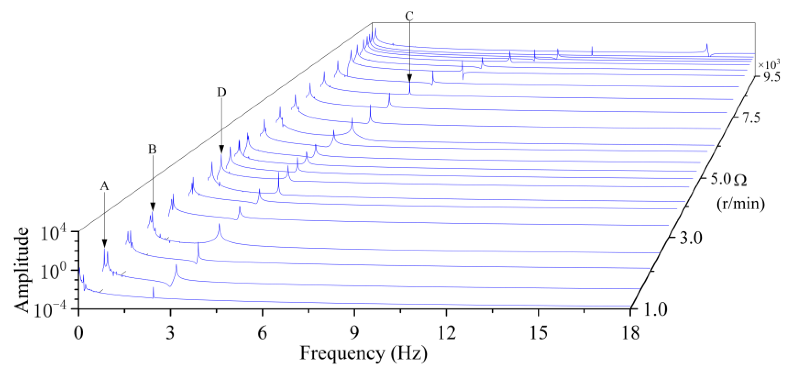
The frequency spectrum of the flapwise motion q ¯ 1 is presented in Figure 4 where peaks A, B and C mark the frequency of the aerodynamic excitation ( f Q ) and the frequencies of the first flapwise mode ( f q ) and the first spanwise mode ( f p ). When Ω escalates to 4300 r/min, primary resonance (point D) in the blade motion occurs as f Q approaches f q . This demonstrates the significant influence of the aerodynamic force through the flapwise movement of the blade. The magnitude of the resonance decays as the two frequencies departs, which in turn reduces the effect of contact and friction on the blade shroud.
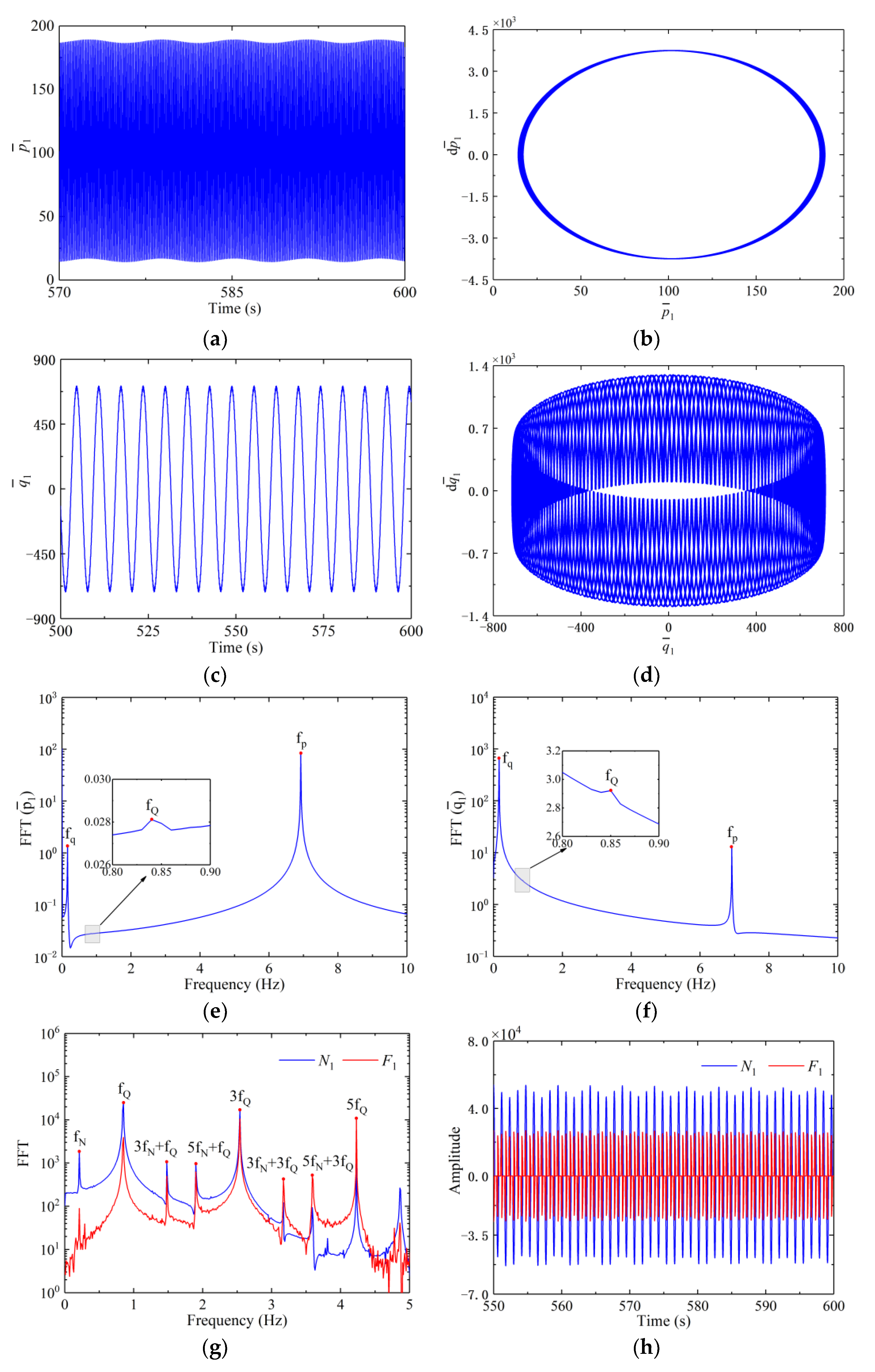
Further examinations are carried out focusing on the vibration response under four selected rotation speeds, i.e., 4300, 4750 and 9000 r/min, and the results are presented in Figure 5. As shown in Figure 5a–d, the spanwise motion p ¯ 1 appears close to periodic, whereas the flapwise q ¯ 1 is not. Further, the primary resonance in the flapwise direction occurs when Ω = 4300 r/min. Based on the fast Fourier transform analysis, p ¯ 1 is dominated by f p in term of amplitude, and is slightly modulated by weak disturbances that carry low frequencies such as f q and f Q . For the flapwise motion q ¯ 1 , all of the frequencies are incommensurable whose amplitudes are in the same scale, Figure 5f. It should be noted that free vibration will be produced by the initial disturbance during each contact along with the forced response resulted from the aerodynamic force on the blade. To be specific f p and f q are frequencies of the free vibration, whereas f Q and its odd multiples are frequencies related to the forced vibration.
As far as the contact and friction on the shroud are concerned, both N 1 and F 1 are non-smooth periodic and spectrally governed by f Q and its odd multiples (e.g., 3 f Q and 5 f Q ) that can be identified in Figure 5g. Further, the direction of the friction force reverses every time the normal force reaches its maximum value, Figure 5h. Both N 1 and F 1 change periodically and vanish when the shroud is completely separated from the other shroud, or the forces by the two adjacent shrouds cancel with each other during contact.
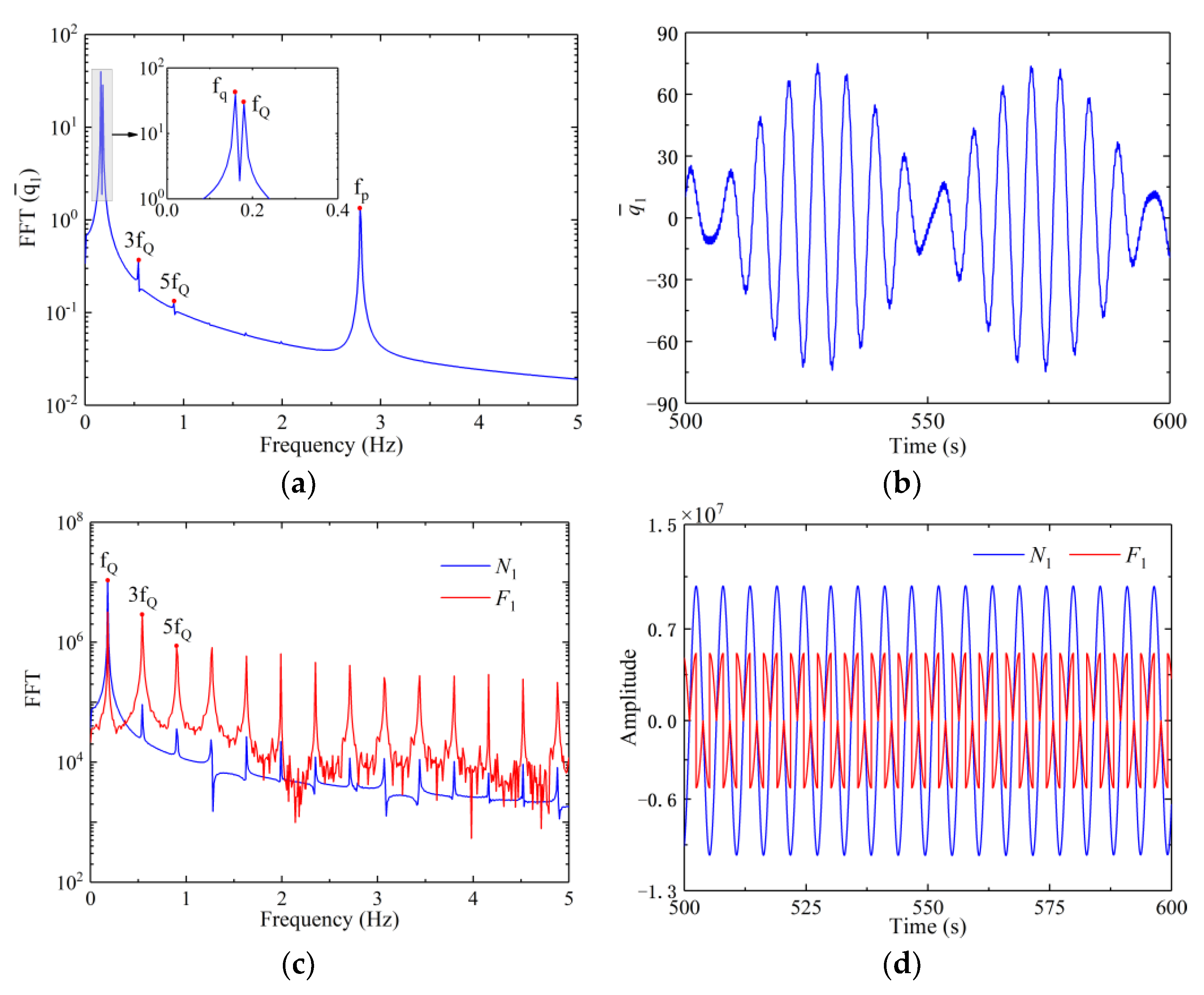
As Ω arrives at 4750 r/min, a slight difference of 0.02 Hz between f Q and f q is found in Figure 6a, and the phenomenon of beat is observed from Figure 6b. The peak-to-peak amplitude of q ¯ 1 enlarges owing to the presence of beat, and so do the contact and friction forces between adjacent shrouds. Further, the net contact and friction forces appear periodic as shown in Figure 6c,d. Moreover, localization of vibration is likely to take places in this case which will be presented in the next subsection.
Finally, when the blade is accelerated to Ω = 9000 r/min, both p ¯ 1 and q ¯ 1 become quasi-periodic, Figure 7a–d. The frequency f Q can hardly be identified from Figure 7e,f. As a matter of fact, the normal contact stiffness becomes smaller at high rotation speed (c.f. Figure 3) and the actions of contact and friction are both weak, which explains the amplitudes associated with f Q are minor in the spectra of p ¯ 1 and q ¯ 1 . Further, as shown in Figure 7g, the spectra of normal and friction forces both contain the identified f N , the aerodynamic frequency f Q and its odd multiples as well as combined frequencies of 3 f N + f Q , 5 f N + f Q , 3 f N + 3 f Q and 5 f N + 3 f Q , etc. This clearly shows the nonlinear yet complicated nature of the vibration induced by the action of the normal and friction forces.
In this study it is found that the primary resonance, beat and quasi-periodic vibration appear successively due to the contact and friction between shrouds with the increase of rotation speed. On the whole, the blisk structures can be designed more reasonably based on the in-depth understandings of these phenomena and are more likely to perform better under the circumstance of vibration localization.

3.2. Localization of Vibration of Blades

Factor of Localization of Vibration
In this section, different form existing publications, we discover a particular type of vibration localization initiated by the contact and friction effect of the shrouds in the form of asymmetric vibration in the tuned bladed, cyclically symmetric disk, then reveal and discuss its influence on the vibration of the blisk. To demonstrate the unevenness in the blade deformations, the maximal displacements of each blade are selected over the period of the vibration and compared individually with their arithmetic means. One may define the following factors of localizations of vibration in the flapwise and spanwise directions, i.e.,
L p = i = 1 n max ( p ¯ i ( t ) ) p ¯ ave p ¯ ave ,   L q = i = 1 n max ( q ¯ i ( t ) ) q ¯ ave q ¯ ave , t > 0
where
p ¯ ave = 1 n i = 1 n max ( p ¯ i ( t ) ) ,   q ¯ ave = 1 n i = 1 n max ( q ¯ i ( t ) )
Note that these factors will be zero if the displacements are constant or circumferentially periodic among the blades.
Next, the maximum displacements are presented in Figure 8 for three cases: the general vibration when Ω = 6000 r/min, the case of beat when Ω = 4750 r/min and the case of blades free of contact and friction when Ω = 4750 r/min. The factors of the localization of vibration are tabulated in Table 2. Factors of localization of vibration in different cases for these three cases. Through examining Figure 8a–c one can see the uneven distribution of maximum displacements as the result of the localization of vibration resulted from the beat, as well as the contact and friction between the perfectly tuned blades. The level of localization is found much stronger in the flapwise direction than in the spanwise direction due to the high tensile stiffness of the blades.

3.3. Effect of Coupling Stiffness on the Localization of Vibration

The interaction among the blades enables the transfer of energy across the disk parts, and influence the contact and friction on the shroud. In the present investigation, such actions can be considered through adopting the cross-coupling stiffness k ¯ 2 n + 1 , i , k ¯ 2 n + 1 , n + i , k ¯ 2 n + 2 , i , k ¯ 2 n + 2 , n + i in Equations (25) and (26). To demonstrate how the localization is affected by the cross coupling, Equations (23) through (26) are solved with various cross-coupling stiffness. For convenience of comparison, these coefficients are amplified by the identical factor denoted by ξ .
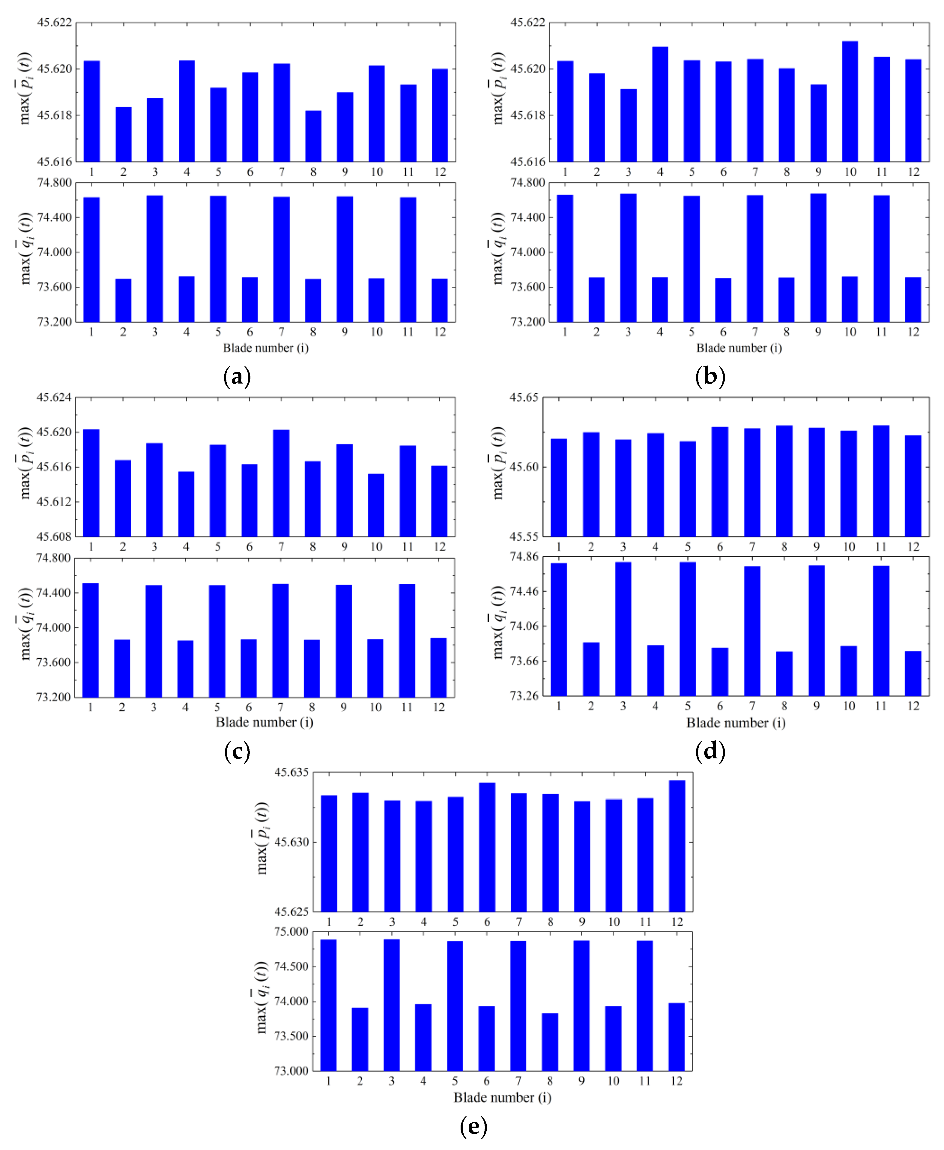
The maximum displacements of the blades are shown in Figure 9 with varying ξ , and the factors of localization are tabulated in Table 3. Based on these results, the factors of localization increase significantly relative to ξ = 1 when the cross-coupling is strong, with L q being more sensitive than L p . This can be explained by the fact that L p is closely related to the spanwise displacements which are governed mainly by the centrifugal force, and hence is insensitive to the cross-coupling effect. Conversely, L q is affected primarily by the contact forces, and hence more prone to the change of the cross-coupling effect.
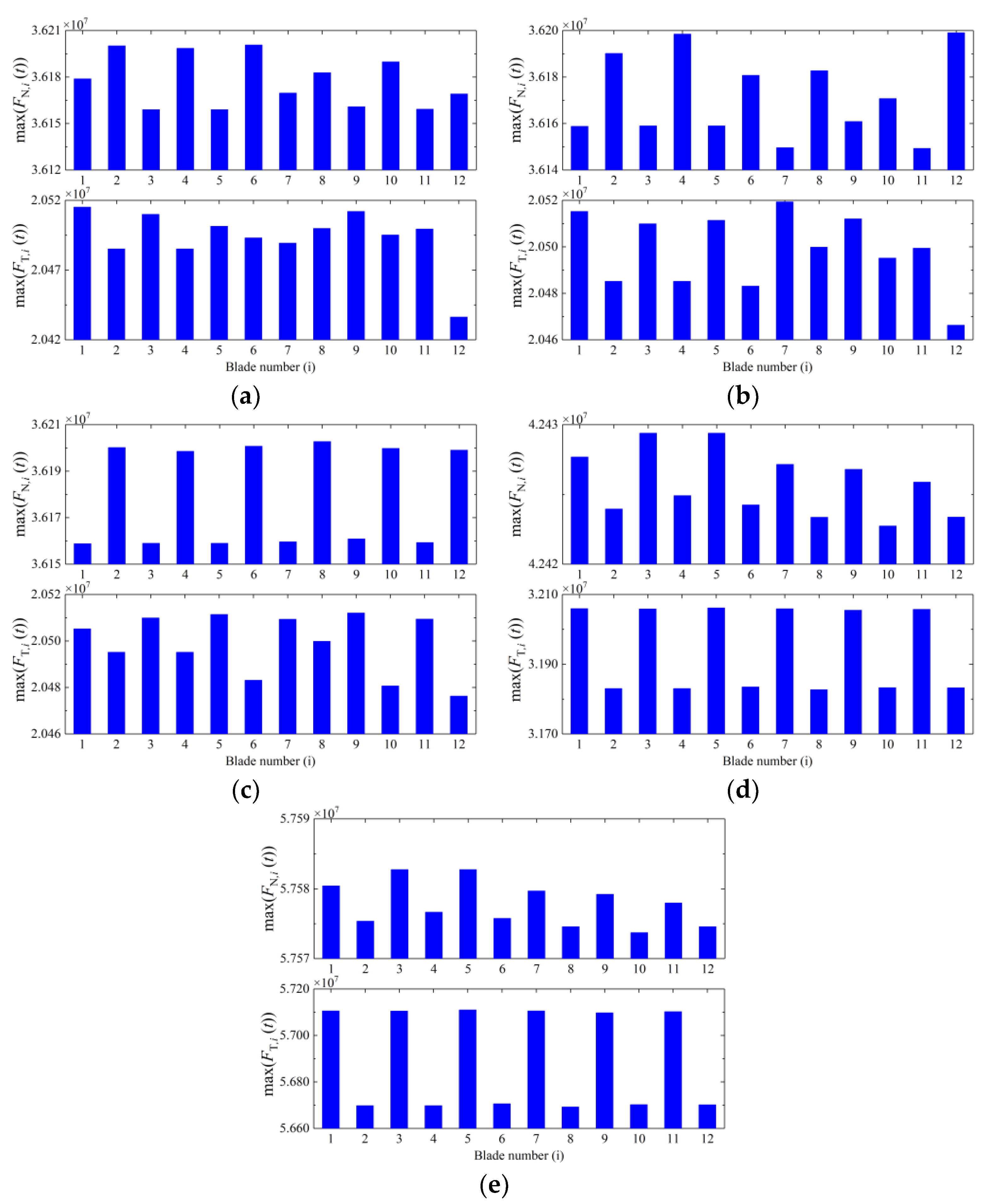
Meanwhile, as shown in Figure 10, the increasing ξ enlarges the normal and tangential disk-blade interactions at the root of the i-th blade (defined as F N , i ( t ) and F T , i ( t ) in Equations (A10) and (A11)), which boosts the energy transferal from the disk to the blades. Consequently, the normal and friction forces on the shroud interfaces will be enhanced, as well as the localization of vibration caused by these forces.

3.4. Power of Blade Vibration under Localization of Vibration

Next, the effect of the localization of vibration on the blade vibration is studied considering varying normal contact stiffness and gap between the adjacent shrouds. To measure the level of the blade motions, a generalized, average power over a period of steady-state vibration is defined
E i = 1 T 0 T [ p i 2 ( t ) + q i 2 ( t ) ] d t , i = 1 , 2 , , n
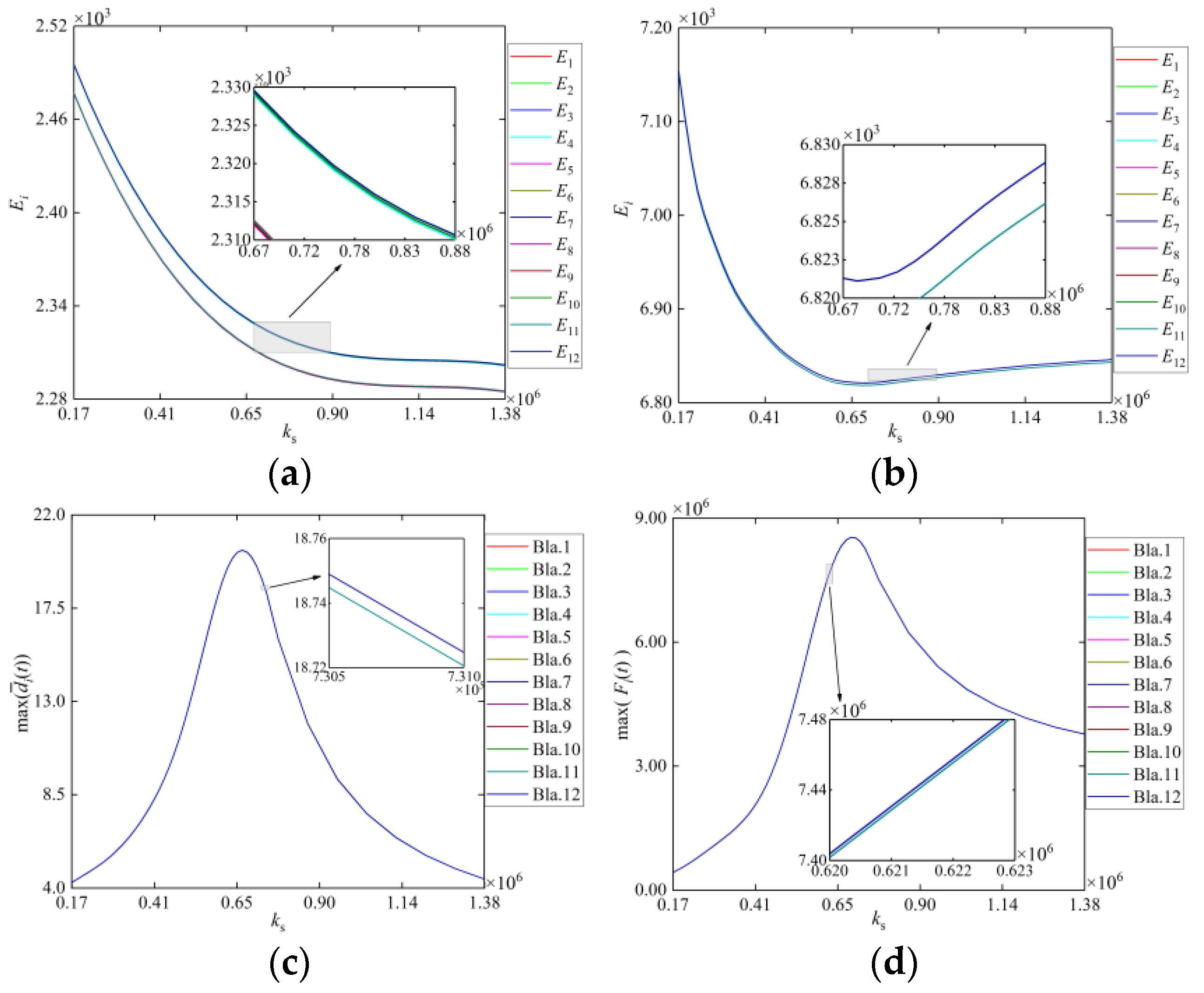
Using various normal contact stiffness between adjacent shrouds ( k s ), the generalized powers of all twelve blade motions are depicted in Figure 11a,b under the localization of vibration and compared to the ones from regular, non-localized vibration. As shown in Figure 11a,b, E i appear confined to two belts of narrowly spaced curves. These belts are separated under the localization of vibration throughout the entire range of k s , which is attributable to the distorted pattern of maximum displacements of the blades (c.f., Figure 8b). When it happens, the localization of vibration tends to produce larger difference in displacements among the blades, thus creating a unique pattern of two groups of E i , each carrying nearly identical powers of vibration. Moreover, it is observed in Figure 11a that they both decrease with k s . As shown previously in Table 3, the localization of vibration can be enhanced by the increase of the normal contact stiffness, which further enlarges the difference in displacements as well as those E i among the blades.
In the non-localization case, the E i drop at first and then escalate when k s increases, Figure 11b. On one hand, more energies are dissipated as friction on the shroud interface grows with the increasing contact forces, which reduces E i . On the other hand, the distance between the adjacent shrouds decreases when k s is large enough (see Figure 11c), which reduces the friction force (see Figure 11d) and consequently, increases the level of E i . Thus, the powers E i decreases unanimously with the increasing normal contact stiffness, Figure 11a. In contrast, these distances are amplified when the localization of vibration is encountered.

4. Conclusions

The nonlinear dynamics and the vibration localization of a whole rotating blisk with the shrouded friction contacts are presented in this paper. A continuous parametric model of a shrouded blisk with short blades of small installation angles is established, and the transition boundaries between different contact statuses (i.e., stick, slip and separation) of the whole shrouded blisk are determined based on the relative motion status of the blades. Using this model, the nonlinear vibration responses with variable rotation speed are analyzed, the particular type of vibration localization initiated by the contact and friction effect of the shrouds is discovered, and its influence on the vibration of the blisk is revealed and discussed. The followings summarize the present study:
(1)
With the increase of rotation speed, the primary resonance, beat and quasi-periodic vibration appear successively due to the contact and friction between shrouds.
(2)
The localization of vibration occurs in tuned shrouded blisks only when the beat exists, i.e., frequency of free vibration slightly differs from the frequency of the forced vibration caused by the contact and friction of shrouds. Further, the level of such localization increases as the blade-disk coupling becomes strong.
(3)
The power of the blade motion drops consistently with the contact stiffness of the shrouds in the localization of vibration, which is different from the non-localization case.

Author Contributions

Conceptualization, G.Y. and Y.W.; methodology, G.Y.; software, G.Y.; validation, G.Y.; formal analysis, G.Y.; investigation, G.Y.; resources, G.Y.; data curation, G.Y.; writing—original draft preparation, G.Y.; writing—review and editing, G.Y. and Y.W. All authors have read and agreed to the published version of the manuscript.

Funding

This research was funded by the National Science and Technology Major Project (Grant 2019-IV-0019-0087), the Natural Science Foundation of China (Grant U1808214) and the International Cooperation Fund of DUT-BSU Joint Institute (Grant ICR2109).

Data Availability Statement

No date need be reported.

Conflicts of Interest

The authors declare no conflict of interest.

Appendix A. Nomenclature of the Most Important Quantities

Table A1. Nomenclature of the most important quantities.
SymbolParameter NamesSymbolParameter Names
c u , c v Viscous damping coefficients in the spanwise and flapwise directions Q i Aerodynamic force
c x , c y Viscous damping coefficients of the disk Q 0 Forcing   amplitude   of   Q i
d i Normal distance between the shrouds u i , v i Spanwise and flapwise displacements of the blade
d r Radius of the disk v r , i Relative velocity aligning with the contact surfaces of the i-th and (i-1)-th shrouds
EA, EITensile and bending stiffness of the blade x d , y d Instantaneous center of disk in the X-, Y-directions
F s , i Friction force of the i-th shroud α Tilt angle of shrouds
k s Normal contact stiffness between adjacent shrouds β Tuning parameter
k x , k y Stiffness coefficients of the shaft to the disk δ s Gap between adjacent shrouds
LLength of the blade λ Number of inlet vanes in the upstream of the blades
m d mass of the disk μ m , μ s Coefficients of minimum kinetic friction and maximum static friction
m s mass of the shrouds ρ l Linear mass density of the blades
N s , i Normal force of the i-th shroud Ω Rotation speed
nTotal number of blades ( ¯ ) Variate after nondimensionalize
p j i , q j i The j-th modal coordinates of the i-th blade

Appendix B. Coefficients in Governing Equations

The coefficients adopted in Equations (15)–(18) are defined as
a i = 0 L Ω 2 ρ l Ψ ( x i + d r ) d x i + Ω 2 m s Ψ ( L ) ( L + d r ) , a 2 n + 1 = i = 1 n Ω 2 [ ρ l ( L 2 2 + d r L ) + m s ( L + d r ) ] cos θ i , a 2 n + 2 = i = 1 n Ω 2 [ ρ l ( L 2 2 + d r L ) + m s ( L + d r ) ] sin θ i
m i , i = 0 L ρ l Ψ Ψ d x i + m s Ψ ( L ) Ψ ( L ) , m i , 2 n + 1 = 0 L ρ l Ψ cos θ i d x i + m s Ψ ( L ) cos θ i , m i , 2 n + 2 = 0 L ρ l Ψ sin θ i d x i + m s Ψ ( L ) sin θ i , m n + i , n + i = 0 L ρ l Φ Φ d x i + m s Φ ( L ) Φ ( L ) , m n + i , 2 n + 1 = 0 L ρ l Φ sin θ i d x i m s Φ ( L ) sin θ i , m n + i , 2 n + 2 = 0 L ρ l Φ cos θ i d x i + m s Φ ( L ) cos θ i , m 2 n + 1 , i = 0 L ρ l Ψ cos θ i d x i + m s Ψ ( L ) cos θ i , m 2 n + 1 , n + i = 0 L ρ l Φ sin θ i d x i m s Φ ( L ) sin θ i , m 2 n + 1 , 2 n + 1 = m 2 n + 2 , 2 n + 2 = m d + n m s + n ρ l L , m 2 n + 2 , i = 0 L ρ l Ψ sin θ i d x i + m s Ψ ( L ) sin θ i , m 2 n + 2 , n + i = 0 L ρ l Φ cos θ i d x i + m s Φ ( L ) cos θ i
k i , i = 0 L E A Ψ Ψ d x i 0 L Ω 2 ρ l Ψ Ψ d x i Ω 2 m s Ψ ( L ) Ψ ( L ) , k n + i , n + i = 0 L E I Φ Φ d x i 0 L Ω 2 ρ l Φ Φ d x i Ω 2 m s Φ ( L ) Φ ( L ) , k 2 n + 1 , i = 0 L ρ l Ω 2 Ψ cos θ i d x i m s Ω 2 Ψ ( L ) cos θ i , k 2 n + 1 , n + i = 0 L ρ l Ω 2 Φ sin θ i d x i + m s Ω 2 Φ ( L ) sin θ i , k 2 n + 1 , 2 n + 1 = k x , k 2 n + 2 , 2 n + 2 = k y , k 2 n + 2 , i = 0 L ρ l Ω 2 Ψ sin θ i d x i m s Ω 2 Ψ ( L ) sin θ i , k 2 n + 2 , n + i = 0 L ρ l Ω 2 Φ cos θ i d x i m s Ω 2 Φ ( L ) cos θ i
g i , n + i = 0 L 2 Ω ρ l Ψ Φ d x i 2 Ω m s Ψ ( L ) Φ ( L ) , g n + i , i = 0 L 2 Ω ρ l Ψ Φ d x i + 2 Ω m s Ψ ( L ) Φ ( L ) , g 2 n + 1 , i = 0 L 2 Ω ρ l Ψ sin θ i d x i 2 Ω m s Ψ ( L ) sin θ i , g 2 n + 1 , n + i = 0 L 2 Ω ρ l Φ cos θ i d x i 2 Ω m s Φ ( L ) cos θ i , g 2 n + 2 , i = 0 L 2 Ω ρ l Ψ cos θ i d x i + 2 Ω m s Ψ ( L ) cos θ i , g 2 n + 2 , n + i = 0 L 2 Ω ρ l Φ sin θ i d x i 2 Ω m s Φ ( L ) sin θ i
c i , i = 0 L c u Ψ Ψ d x i , c n + i , n + i = 0 L c v Φ Φ d x i , c 2 n + 1 , 2 n + 1 = c x , c 2 n + 2 , 2 n + 2 = c y
where i = 1, 2, …, n.
The coefficients adopted in Equations (23)–(26) are defined in the followings, respectively,
m ¯ i , 2 n + 1 = m i , 2 n + 1 m i , i , m ¯ i , 2 n + 2 = m i , 2 n + 2 m i , i , c ¯ i , i = c i , i ω n + i m i , i , g ¯ i , n + i = g i , n + i ω n + i m i , i , ω ¯ i 2 = ω i 2 ω n + i 2 , m ¯ q p = m n + i , n + i m i , i
m ¯ n + i , 2 n + 1 = m n + i , 2 n + 1 m n + i , m ¯ n + i , 2 n + 2 = m n + i , 2 n + 2 m n + i , g ¯ n + i , i = g n + i , i ω n + i m n + i , n + i , c ¯ n + i , n + i = c n + i , n + i ω n + i m n + i , n + i
m ¯ 2 n + 1 , i = m 2 n + 1 , i m 2 n + 1 , 2 n + 1 , m ¯ 2 n + 1 , n + i = m 2 n + 1 , n + i m 2 n + 1 , 2 n + 1 , c ¯ 2 n + 1 , 2 n + 1 = c 2 n + 1 , 2 n + 1 ω n + i m 2 n + 1 , 2 n + 1 , g ¯ 2 n + 1 , i = g 2 n + 1 , i ω q m 2 n + 1 , 2 n + 1 , g ¯ 2 n + 1 , n + i = g 2 n + 1 , n + i ω q m 2 n + 1 , 2 n + 1 , k ¯ 2 n + 1 , i = k 2 n + 1 , i ω n + i 2 m 2 n + 1 , 2 n + 1 , k ¯ 2 n + 1 , n + i = k 2 n + 1 , n + i ω n + i 2 m 2 n + 1 , 2 n + 1 , ω ¯ 2 n + 1 2 = ω 2 n + 1 2 ω n + i 2 ,
m ¯ 2 n + 2 , i = m 2 n + 2 , i m 2 n + 2 , 2 n + 2 , m ¯ 2 n + 2 , n + i = m 2 n + 2 , n + i m 2 n + 2 , 2 n + 2 , c ¯ 2 n + 2 , 2 n + 2 = c 2 n + 2 , 2 n + 2 ω n + i m 2 n + 2 , 2 n + 2 , g ¯ 2 n + 2 , i = g 2 n + 2 , i ω n + i m 2 n + 2 , 2 n + 2 , g ¯ 2 n + 2 , n + i = g 2 n + 2 , n + i ω n + i m 2 n + 2 , 2 n + 2 , k ¯ 2 n + 2 , i = k 2 n + 2 , i ω n + i 2 m 2 n + 2 , 2 n + 2 , k ¯ 2 n + 2 , n + i = k 2 n + 2 , n + i ω n + i 2 m 2 n + 2 , 2 n + 2 , ω ¯ 2 n + 2 2 = ω 2 n + 2 2 ω n + i 2
The reaction forces in the normal and tangential directions are defined as
F N , i ( t ) = 0 L ρ l ( x ¯ d cos θ i + y ¯ d sin θ i + u ¯ i 2 Ω v ¯ i Ω 2 u ¯ i ) d x i   m s ( x ¯ d cos θ i + y ¯ d sin θ i + u ¯ i 2 Ω v ¯ i Ω 2 u ¯ i )   + Ω 2 ρ l L ( L 2 + d r ) + Ω 2 m s ( L + d r )   N ¯ s , i + 1 cos α + F ¯ s , i + 1 sin α + N ¯ s , i cos α F ¯ s , i sin α
and
F T , i ( t ) = 0 L ρ l ( x ¯ d sin θ i + y ¯ d cos θ i + v ¯ i + 2 Ω u ¯ i Ω 2 v ¯ i ) d x i   m s ( x ¯ d sin θ i + y ¯ d cos θ i + v ¯ i + 2 Ω u ¯ i Ω 2 v ¯ i )   Q ¯ i N ¯ s , i + 1 sin α F ¯ s , i + 1 cos α + N ¯ s , i sin α + F ¯ s , i cos α

Appendix C. Friction Force with Different Contact States

Three states of contact can exist on shroud interfaces during vibration:
  • There is no contact between adjacent shrouds. In this case, one has d ¯ i 0 ( i = 1 , 2 , , n ) , and the value of the friction force on the shroud interface is zero.
  • Contact exists between the i-th ( i = 1 , 2 , , n ) and (i-1)-th shrouds. In this case, one has d ¯ i > 0 , and three scenarios can happen as follows.
    (a)
    If the i-th shroud is slipping relatively to the (i-1)-th shroud, s r , i 0 . The sliding friction of the i-th blade is expressed as
    F ¯ s , i = μ ( s r , i ) N ¯ s , i sgn ( s r , i )
    (b)
    If the i-th shroud is sticking relatively to the (i-1)-th shroud, one has s r , i = 0 , q ¯ i = q ¯ i 1 , p ¯ i = p ¯ i 1 , q ¯ i = q ¯ i 1 . In the flapwise direction the equation becomes
    q ¯ i + m ¯ n + i , 2 n + 1 x ¯ d + m ¯ n + i , 2 n + 2 y ¯ d + g ¯ n + i , i p ¯ i + c ¯ n + i , n + i q ¯ i + q ¯ i = Q ¯ i + N ¯ s , i sin α + F ¯ s , i cos α
    The flapwise equation of the (i-1)-th blade is expressed as
    q ¯ i 1 + m ¯ n + i 1 , 2 n + 1 x ¯ d + m ¯ n + i 1 , 2 n + 2 y ¯ d + g ¯ n + i 1 , i 1 p ¯ i 1 + c ¯ n + i 1 , n + i 1 q ¯ i 1 + q ¯ i 1 = Q ¯ i 1 N ¯ s , i sin α F ¯ s , i cos α
    Further, one has
    q ¯ i q ¯ i 1 = Q ¯ i + Q ¯ i 1 + 2 N ¯ s , i sin α + 2 F ¯ s , i cos α
    The static friction forces F ¯ s , i is written as
    F ¯ s , i = 1 2 cos α [ q ¯ i q ¯ i 1 + Q ¯ i Q ¯ i 1 2 N ¯ s , i sin α ]
    (c)
    If s r , i = 0 but | F ¯ s , i | > μ ( s r , i ) N ¯ s , i , the friction force reverses its direction. At this moment, the i-th shroud is slipping relatively to the (i-1)-th shroud.
  • There is contact between n c ( n c 3 ) consecutive shrouds. It is assumed that the j-th ( j = i , , i + n c 2 ) shroud is connected to its adjacent shrouds, and thus d ¯ j > 0 . Two different statuses are differentiated in this situation.
    (a)
    If both the j-th shrouds are sticking relatively to adjacent shrouds, s r , j = 0 , q ¯ i 1 = q ¯ i = = q ¯ i + n c 2 , p ¯ i 1 = p ¯ i = = p ¯ i + n c 2 , q ¯ i 1 = q ¯ i = = q ¯ i + n c 2 . In flapwise direction of the ( i + n c 2 ) -th shroud, the equation of motion reads
    q ¯ i + n c 2 + m ¯ n + i + n c 2 , 2 n + 1 x ¯ d + m ¯ n + i + n c 2 , 2 n + 2 y ¯ d + g ¯ n + i + n c 2 , i + n c 2 p ¯ i + n c 2 + c ¯ i + n c 2 , i + n c 2 q ¯ i + n c 2 + q ¯ i + n c 2 = Q ¯ i + n c 2 + N ¯ s , i + n c 2 sin α + F ¯ s , i + n c 2 cos α
    The flapwise equation of the l-th ( l = i , , i + n c 3 ) blade reads
    q ¯ l + m ¯ n + l , 2 n + 1 x ¯ d + m ¯ n + l , 2 n + 2 y ¯ d + g ¯ n + l , l p ¯ l + c ¯ l , l q ¯ l + q ¯ l = Q ¯ l N ¯ s , l + 1 sin α F ¯ s , l + 1 cos α + N ¯ s , l sin α + F ¯ s , l cos α
    The flapwise equation of the (i-1)-th blade reads
    q ¯ i 1 + m ¯ n + i 1 , 2 n + 1 x ¯ d + m ¯ n + i 1 , 2 n + 2 y ¯ d + g ¯ n + i 1 , i 1 p ¯ i 1 + c ¯ i 1 , i 1 q ¯ i 1 + q ¯ i 1 = Q ¯ i 1 N ¯ s , i sin α F ¯ s , i cos α
    Based on Equations (A17)–(A19). The sticking friction force of the ( i + n c 2 ) -th blade is derived, as
    F ¯ s , i + n c 2 = 1 n c cos α { ( n c 1 ) ( q ¯ i + n c 2 + Q ¯ i + n c 2 ) j = i 1 i + n c 3 ( q ¯ j + Q ¯ j ) n c N ¯ s , i + n c 2 sin α } .
    Similarly, the static friction force of the r-th blade ( r = i , , i + n c 3 ) is
    F ¯ s , r = 1 ( r i + 2 ) cos α { ( r i + 1 ) ( q ¯ r + Q ¯ r ) j = i 1 r 1 ( q ¯ j + Q ¯ j ) ( r i + 2 ) N ¯ s , r sin α + ( r i + 1 ) ( N ¯ s , r sin α + F ¯ s , r + 1 cos α ) }
    (b)
    If the m-th shroud is slipping relatively to the (m-1)-th shroud whole other shrouds are sticking relatively to adjacent shrouds, s r , m 0 . Different from Equations (A20) and (A21), the sliding friction force of the m-th blade becomes
    F ¯ s , m = μ ( s r , m ) N ¯ s , m sgn ( s r , m )

Appendix D. Process of the Dichotomy Method

The dichotomy method is used to solve the actual change moment of the contact state of the shroud. Before solving governing Equations (23)–(26) in the paper, the state variables of the equations at the initial moment (t0) and the current moment (tend) are given, thus, the range (t0, tend) is the initial range of the dichotomy method. The state variable of the equations at tend can be obtained though the Runge-Kutta method. If the contact states at t0 and tn are different, the dichotomy method should be used to find out the actual changing moment of the contact state, otherwise, it is not necessary. The process can be summarized as follows:
Firstly, one defines t0,0 = t0, tend,0 = tend, dt1 = (tend − t0)/21 and tmid,1 = t0,0 + dt1, where subscript 1 represents the first cycle of the dichotomy method.
Then, one decides whether the contact state changes on the left or right side of tmid,1. If the state changes on the left side of tmid,1, continue to denote that t0,1 = t0,0 and tend,1 = tmid,1. Otherwise, denote that t0,1 = tmid,1 and tend,1 = tend,0. Therefore, the range of the dichotomy method is updated to (t0,1, tend,1).
Finally, one repeats the above process with t0,1 and tend,1 as the initial value until the error between t0,i and tend,i is less than the specified tolerance, then tend,i is taken as the actual change moment of the contact state.

Appendix E. Parameters of the Finite Element Model

The blades and shrouds are made of the same material in ANSYS, and the gross parameters of the finite element model are as follows:
Table A2. Gross parameters of the finite element model.
Parameter NamesValue
The length and width of the blade cross section0.01, 0.15 m
The length, width and thickness of the shroud0.01, 0.15, 0.02 m
Density4500 kg/m3
Young’s modulus116 GPa
Poisson’s ratio0.3

References

  1. Carter, T.J. Common failures in gas turbine blades. Eng. Fail. Anal. 2005, 12, 237–247. [Google Scholar] [CrossRef]
  2. Cigeroglu, E. Development of Microslip Friction Models and Forced Response Prediction Methods for Frictionally Constrained Turbine Blades. Ph.D. Thesis, The Ohio State University, Columbus, OH, USA, 2007. [Google Scholar]
  3. Chu, S.; Cao, D.; Sun, S.; Pan, J.; Wang, L. Impact vibration characteristics of a shrouded blade with asymmetric gaps under wake flow excitations. Nonlinear Dyn. 2013, 72, 539–554. [Google Scholar] [CrossRef]
  4. Chiu, Y.J.; Chen, D.Z.; Yang, C.H. Influence on Coupling Vibration of Rotor System with Grouped Blades due to Mistuned Lacing Wire. Appl. Mech. Mater. 2011, 101–102, 1119–1125. [Google Scholar] [CrossRef]
  5. Ma, H.; Xie, F.; Nai, H.; Wen, B. Vibration characteristics analysis of rotating shrouded blades with impacts. J. Sound Vib. 2016, 378, 92–108. [Google Scholar] [CrossRef]
  6. Chatterjee, A.; Kotambkar, M.S. Modal characteristics of turbine blade packets under lacing wire damage induced mistuning. J. Sound Vib. 2015, 343, 49–70. [Google Scholar] [CrossRef]
  7. Petrov, E.P.; Sanliturk, K.Y.; Ewins, D.J. A New Method for Dynamic Analysis of Mistuned Bladed Disks Based on the Exact Relationship Between Tuned and Mistuned Systems. J. Eng. Gas Turbines Power 2002, 124, 586–597. [Google Scholar] [CrossRef]
  8. Petrov, E.P. Method for direct parametric analysis of nonlinear forced response of bladed disks with friction contact interfaces. J. Turbomach. 2004, 126, 654–662. [Google Scholar] [CrossRef]
  9. Karimi, A.H.; Shadmani, M. Nonlinear vibration analysis of a beam subjected to a random axial force. Arch. Appl. Mech. 2019, 89, 385–402. [Google Scholar] [CrossRef]
  10. Iwan, W.D. On a Class of Models for the Yielding Behavior of Continuous and Composite Systems. J. Appl. Mech. 1967, 34, 612–617. [Google Scholar] [CrossRef]
  11. Griffin, J.H. Friction Damping of Resonant Stresses in Gas Turbine Engine Airfoils. J. Eng. Power 1980, 102, 329–333. [Google Scholar] [CrossRef]
  12. Menq, C.H.; Bielak, J.; Griffin, J.H. The influence of microslip on vibratory response, part I: A new microslip model. J. Sound Vib. 1986, 107, 279–293. [Google Scholar] [CrossRef]
  13. Cigeroglu, E.; An, N.; Menq, C.H. A microslip friction model with normal load variation induced by normal motion. Nonlinear Dyn. 2007, 50, 609–626. [Google Scholar] [CrossRef]
  14. Yang, B.D.; Menq, C.H. Characterization of 3D contact kinematics and prediction of resonant response of structures having 3D frictional constraint. J. Sound Vib. 1998, 217, 909–925. [Google Scholar] [CrossRef]
  15. Peterka, F.; Vacík, J. Transition to chaotic motion in mechanical systems with impacts. J. Sound Vib. 1992, 154, 95–115. [Google Scholar] [CrossRef]
  16. Peterka, F. Bifurcations and transition phenomena in an impact oscillator. Chaos Solitons Fractals 1996, 7, 1635–1647. [Google Scholar] [CrossRef]
  17. Brach, R.M. Mechanical Impact Dynamics: Rigid Body Collisions; John Wiley & Sons: New York, NY, USA, 1991; pp. 248–249. ISBN 0471508454. [Google Scholar]
  18. Liu, Y.; Shangguan, B.; Xu, Z. A friction contact stiffness model of fractal geometry in forced response analysis of a shrouded blade. Nonlinear Dyn. 2012, 70, 2247–2257. [Google Scholar] [CrossRef]
  19. Li, C.; Liu, X.; Tang, Q.; Chen, Z. Modeling and nonlinear dynamics analysis of a rotating beam with dry friction support boundary conditions. J. Sound Vib. 2021, 498, 115978. [Google Scholar] [CrossRef]
  20. He, B.; Ouyang, H.; He, S.; Mei, Y. Dynamic analysis of integrally shrouded group blades with rubbing and impact. Nonlinear Dyn. 2018, 92, 2159–2175. [Google Scholar] [CrossRef]
  21. Mashayekhi, F.; Nobari, A.S.; Zucca, S. Hybrid reduction of mistuned bladed disks for nonlinear forced response analysis with dry friction. Int. J. Non-Linear Mech. 2019, 116, 73–84. [Google Scholar] [CrossRef]
  22. She, H.; Li, C.; Tang, Q.; Wen, B. Veering and merging analysis of nonlinear resonance frequencies of an assembly bladed disk system. J. Sound Vib. 2021, 493, 115818. [Google Scholar] [CrossRef]
  23. Wei, S.T.; Pierre, C. Localization Phenomena in Mistuned Assemblies with Cyclic Symmetry Part II: Forced Vibrations. J. Vib. Acoust. 1988, 110, 439–449. [Google Scholar] [CrossRef]
  24. Fang, X.; Tang, J.; Jordan, E.; Murphy, K.D. Crack induced vibration localization in simplified bladed-disk structures. J. Sound Vib. 2006, 291, 395–418. [Google Scholar] [CrossRef]
  25. Picou, A.; Capiez-Lernout, E.; Soize, C.; Mbaye, M. Robust dynamic analysis of detuned-mistuned rotating bladed disks with geometric nonlinearities. Comput. Mech. 2020, 65, 711–730. [Google Scholar] [CrossRef]
  26. Zhao, W.; Zhang, D.; Xie, Y. Vibration analysis of mistuned damped blades with nonlinear friction and contact. J. Low Freq. Noise Vib. Act. Control 2019, 38, 1505–1521. [Google Scholar] [CrossRef]
  27. Pesaresi, L.; Armand, J.; Schwingshackl, C.W.; Salles, L.; Wong, C. An advanced underplatform damper modelling approach based on a microslip contact model. J. Sound Vib. 2018, 436, 327–340. [Google Scholar] [CrossRef]
  28. Chen, Z.; Li, C.; Yang, Z.; She, H. A new method of micro-slip contact normal pressure modeling and its application in the dynamic analysis of the dovetail–tenon–mortise jointed blades. Mech. Based Des. Struct. Mach. 2022. [Google Scholar] [CrossRef]
  29. Joannin, C.; Chouvion, B.; Thouverez, F.; Mbaye, J.P. Nonlinear Modal Analysis of Mistuned Periodic Structures Subjected to Dry Friction. J. Eng. Gas Turbines Power 2016, 138, 072504. [Google Scholar] [CrossRef]
  30. Thouverez, F.; Grolet, A.; Gibert, C. Non-linear periodic solutions of bladed disks. In Proceedings of the Eurodyn 2014: Ix International Conference on Structural Dynamics, Porto, Portugal, 30 June–2 July 2014. [Google Scholar]
  31. Mehrdad Pourkiaee, S.; Zucca, S. A Reduced Order Model for Nonlinear Dynamics of Mistuned Bladed Disks With Shroud Friction Contacts. J. Eng. Gas Turbines Power 2019, 141, 011031. [Google Scholar] [CrossRef]
  32. She, H.; Li, C.; Tang, Q.; Ma, H.; Wen, B. Computation and investigation of mode characteristics in nonlinear system with tuned/mistuned contact interface. Front. Mech. Eng. 2020, 15, 133–150. [Google Scholar] [CrossRef]
  33. Vakakis, A.F.; Manevitch, L.I.; Mikhlin, Y.V.; Pilipchuk, V.N.; Zevin, A.A. Normal Modes and Localization in Nonlinear Systems; John Wiley & Sons: New York, NY, USA, 1996; pp. 285–304. ISBN 0-471-13319-1. [Google Scholar]
  34. Vakakis, A.F.; Cetinkaya, C. Mode localization in a class of multidegree-of-freedom nonlinear systems with cyclic system. SIAM J. Appl. Math. 1993, 53, 265–282. [Google Scholar] [CrossRef] [Green Version]
  35. Grolet, A.; Thouverez, F. Vibration analysis of a nonlinear system with cyclic symmetry. J. Eng. Gas Turbines Power 2010, 133, 022502. [Google Scholar] [CrossRef]
  36. Fontanela, F.; Grolet, A.; Salles, L.; Hoffmann, N. Computation of quasi-periodic localised vibrations in nonlinear cyclic and symmetric structures using harmonic balance methods. J. Sound Vib. 2019, 438, 54–65. [Google Scholar] [CrossRef]
  37. Berger, E. Friction modeling for dynamic system simulation. Appl. Mech. Rev. 2002, 55, 535–577. [Google Scholar] [CrossRef]
  38. Meirovitch, L. Fundamentals of Vibrations; McGraw-Hill Companies: New York, NY, USA, 2001; pp. 399–401. ISBN 0-07-118174-1. [Google Scholar]
  39. Shadmani, M.; Tikani, R.; Ziaei-Rad, S. On using a distributed-parameter model for modal analysis of a mistuned bladed disk rotor and extracting the statistical properties of its in-plane natural frequencies. J. Sound Vib. 2019, 438, 324–343. [Google Scholar] [CrossRef]
Figure 1. Sketch of a rotating shrouded blisk.
Machines 11 00238 g001
Figure 2. Schematic of the mechanical model of a shrouded blisk. (a) Disk model and (b) Blade geometry in the plane of rotation.
Machines 11 00238 g002
Figure 3. Calculation and fitting of normal contact stiffness. (a) Finite element model and (b) Fitted curve of the contact stiffness.
Machines 11 00238 g003
Figure 4. Waterfall plot of the frequency spectra of q ¯ 1 under variable Ω . Peaks A, B and C mark the frequency of the aerodynamic excitation, the first flapwise mode and the first spanwise mode, respectively. Peak D marks Ω at which primary resonance occurs.
Machines 11 00238 g004
Figure 5. Steady-state responses of the first blade when Ω = 4300 r/min. (a) Time history and (b) Phase diagram of p ¯ 1 ; (c) Time history and (d) Phase diagram of q ¯ 1 ; Frequency spectra of (e) p ¯ 1 and (f) q ¯ 1 ; (g) Frequency spectra and (h) Time histories of N 1 and F 1 . f Q = 0.16 , f q = 0.16 and f p = 2.72 Hz.
Machines 11 00238 g005
Figure 6. Steady-state responses of the first blade when Ω = 4750 r/min. (a) Frequency spectrum and (b) Time history of q ¯ 1 ; (c) Frequency spectra and (d) Time histories of N 1 and F 1 . f q = 0.16 , f Q = 0.18 and f p = 2.79 Hz.
Machines 11 00238 g006
Figure 7. Steady-state responses of the first blade when Ω = 9000 r/min. (a) Time history and (b) Phase diagram of p ¯ 1 ; (c) Time history and (d) Phase diagram of q ¯ 1 ; Frequency spectra of (e) p ¯ 1 and (f) q ¯ 1 ; (g) Frequency spectra and (h) Time histories of N 1 and F 1 . f q = 0.16 , f N = 0.21 , f Q = 0.85 and f p = 6.92 Hz.
Machines 11 00238 g007
Figure 8. Maximum displacements of the blades (a) General case with Ω = 6000 r/min; (b) The beat case with Ω = 4750 r/min and (c) Contact- and friction free with Ω = 4750 r/min.
Machines 11 00238 g008
Figure 9. Maximum displacements of the blades when Ω = 4750 r/min. (a) ξ = 0.01; (b) ξ = 0.1; (c) ξ = 1; (d) ξ = 10 and (e) ξ = 100.
Machines 11 00238 g009
Figure 10. Reaction forces of the disk against the blades at the blade roots when Ω = 4750 r/min. (a) ξ = 0.01; (b) ξ = 0.1; (c) ξ = 1; (d) ξ = 10 and (e) ξ = 100.
Machines 11 00238 g010
Figure 11. Generalized powers and maximum of the steady-state responses of blade motions versus k s . (a) With localization of vibration ( Ω = 4750 r/min) and (b) without localization of vibration ( Ω = 6000 r/min); (c) normal distance between the shrouds and (d) friction force when Ω = 6000 r/min.
Machines 11 00238 g011
Table 1. Gross parameters of the shrouded blisk.
NotationValueNotationValue
c u , c v 1·N·s·m−1 c x , c y 5 N·s·m−1
d r 0.5 mEI1.45 × 103 N·m2
EA1.74 × 108 N k x , k y 1.0 × 10⁷ N·m−1
L0.5 m m d 14.04 kg
m s 0.135 kg Q 0 50 N
α π 3 rad β 5 s·m−1
δ s 2.0 × 10⁻⁵ m λ 1
μ s 0.5 μ m 0.3
ρ l 6.75 kg·m−1Ω6000 r·min−1
Table 2. Factors of localization of vibration in different cases.
ξ L p L q
General case, Ω = 6000 r/min0.00.0
The beat case, Ω = 4750 r/min−3.902 × 10−5−1.197 × 10⁻⁴
Contact- and friction free, Ω = 4750 r/min0.00.0
Table 3. Factors of the localization of vibration. Ω = 4750 r/min.
ξ L p L q
0.01−5.024 × 10−51.190 × 10−5
0.12.003 × 10−5−3.704 × 10⁻⁵
1−3.902 × 10⁻⁵−1.197 × 10⁻⁵
102.429 × 10−50.0017
1006.471 × 10−50.0063
Disclaimer/Publisher’s Note: The statements, opinions and data contained in all publications are solely those of the individual author(s) and contributor(s) and not of MDPI and/or the editor(s). MDPI and/or the editor(s) disclaim responsibility for any injury to people or property resulting from any ideas, methods, instructions or products referred to in the content.