Abstract
Permanent magnet synchronous generators (PMSGs) with high output density per unit volume are becoming widespread in wind-power generation systems. Among them, spoke-type PMSGs are more challenging to magnetize than other PMSGs, owing to their structural characteristics. Magnetization performance is critical because it is directly related to the demagnetization and mass productivity of permanent magnets, and load performance is reduced when non-magnetization occurs due to the low magnetization performance. Additionally, the starting performance is crucial in wind turbines and is influenced by the cogging torque of the PMSG. This is because starting a wind turbine with a large cogging torque is more challenging. Therefore, this study proposes a spoke-type PMSG rotor shape design for low capacity wind turbines that considers magnetization and cogging torques. We analyzed the principle of magnetization and the factors influencing magnetization performance, and designed a rotor shape with improved magnetization performance. Additionally, we applied an asymmetric rotor barrier structure to reduce the cogging torque and analyze the performance of the final model using finite element analysis. We analyzed the temperature saturation during the operation of the final model using a thermal network method and validated the irreversible demagnetization accordingly.
1. Introduction
Wind power generation systems are environmentally friendly, economically feasible, and widely used [1,2,3,4,5,6]. The performance of the generator in a wind power generation system is critical because it is directly related to the efficiency and weight reduction in the system. Widely used generator types include reluctance, induction, and permanent magnet generators. Among them, the most commonly used is the permanent magnet synchronous generator (PMSG), which has a high output density per unit volume and is suitable for miniaturization [7,8,9,10,11]. It uses heavy rare earth magnets with high residual magnetic flux density and coercive force. Therefore, it has high energy density, high output, and a high level of efficiency. However, heavy rare earth magnets have limitations, such as their high cost and unstable supply and demand [12,13]. Conversely, ferrite magnets have a more stable supply–demand relationship and are cheaper than heavy rare earth magnets; however, they generally have poor performance [14,15,16,17,18]. To overcome this limitation, a spoke-type structure is developed in which a magnet can be inserted in the radial direction. The output per unit volume can be improved by concentrating the magnetic flux on the pole piece by inserting a magnet in the radial direction. However, this structure is unfavorable for magnetization. If the magnetization is imperfect, a certain area might remain non-magnetized, and the target performance could not be satisfied during the load operation, owing to a decrease in the residual flux density [19,20,21,22].
The starting performance is crucial in wind-power generation systems. Small wind turbines must be able to start operation even at low wind speeds. Mechanical factors that influence the starting of permanent magnet generators include turbine blade design and shaft friction, whereas electromagnetic factors include the cogging torque. The starting torque generated by the wind must overcome the cogging torque and mechanical friction; therefore, reducing the cogging torque is crucial in the design of wind turbines. Moreover, the cogging torque influences the vibration and noise of the wind turbine as well as the torque ripple. The torque ripple increases with cogging torque; this distorts the waveform, and a sine wave cannot be easily created, thereby reducing generator efficiency. Therefore, a design that considers permanent magnetization and cogging torque is required to obtain a waveform that is amenable to high generator efficiency.
This study proposes a spoke-type PMSG design for wind turbines that considers magnetization. First, we described the types, advantages, and disadvantages of the magnetization method. Subsequently, we analyzed the factors to be considered during magnetization after assembly. We utilized a 500 W class PMSG as a model to design and propose a rotor shape with improved magnetization performance. Additionally, we decreased the cogging torque via the asymmetric design of the barrier in the rotor to improve the starting performance. Finally, we confirmed the validity of the PMSG performance using the proposed shape using FEM. In addition, a prototype was manufactured and tested.
2. Spoke Type Rotor Magnetization Analysis
2.1. Principle of Magnetization
The magnetic flux in a permanent magnet (PM) is formed by the internal magnetization density and external magnetic field strength, as shown in Equation (1) [23]:
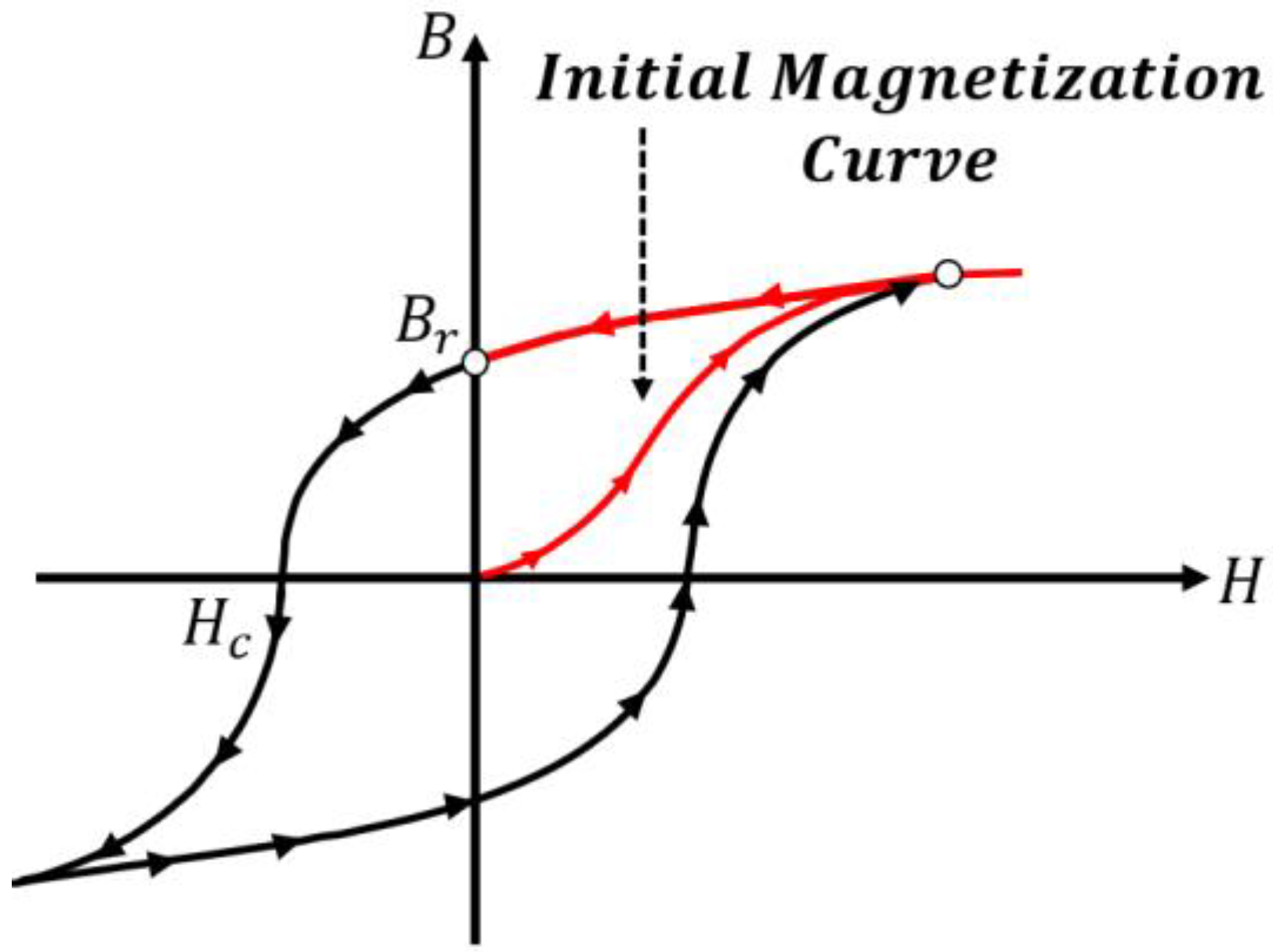
where μ0 is the vacuum permeability; M is the internal magnetization density; and H is the external magnetic field strength. The characteristics of M are determined according to the PM type, and H is the external magnetic field strength, which is determined by the number of turns of the magnetizer and the magnitude of the magnetizing current. The hysteresis curve of the PM is shown in Figure 1 [24]. The non-magnetized PM has a nonlinear initial magnetization curve and an initial point with H = 0 and B = 0.

Figure 1.
Hysteresis curve and magnetization principle of a PM.
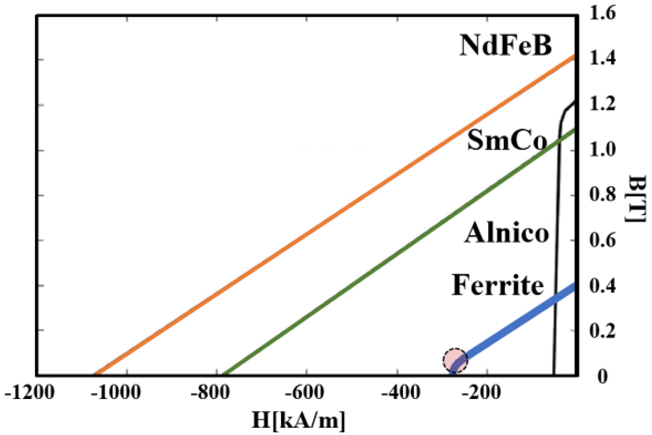
When a magnetic field is applied externally, the magnetic flux density increases along the initial magnetization curve of the PM. If the intensity of the external magnetic field is insufficient, the magnetic flux density cannot attain saturation. When the saturation point is attained by applying a sufficiently strong, external magnetic flux, the residual magnetic flux density reaches the maximum point, and the PM is magnetized according to the aforementioned principles. Conversely, irreversible demagnetization occurs when a reverse magnetic field exceeding Hc passes through a permanent magnetic flux. Ferrite magnets are generally used in the spoke-type setup, and a comparison of the B-H characteristics of ferrite and other PMs is shown in Figure 2 [24].
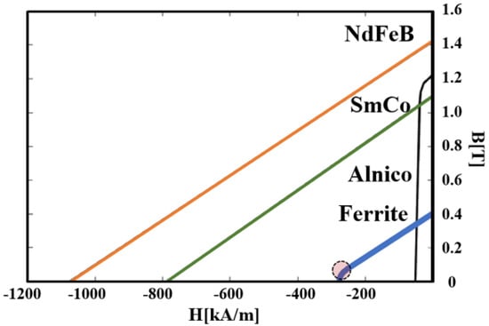
Figure 2.
Comparison of B−H curves among different PM materials.
As shown in Figure 2, ferrite has a lower coercive force than rare earth PMs. Therefore, ferrites can be magnetized using a magnetic flux that is lower than that of rare earth magnets. However, ferrite magnetization is challenging because the PM is inserted vertically.
2.2. PM Magnetization Method
Generally, a PM can be magnetized using one of three methods, as shown in Figure 3.
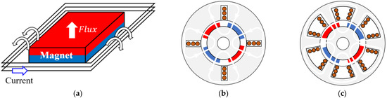
Figure 3.
PMSG magnetization methods: (a) single component, (b) yoke, (c) stator.
In the single–component method, the magnet is magnetized as a single unit, as shown in Figure 3a. This is well suited for complete magnetization; however, inserting a magnet into the rotor creates an attractive force between the rotor core and PM. Alternatively, an attractive or repulsive force may occur with the already inserted magnet. This makes the system challenging to manufacture because the insertion requires a large force, or the PM may break if it collides with the core. In the yoke method, a magnetizing yoke is used after a magnet that has not yet been magnetized is placed in the rotor, as shown in Figure 3b. This material ensures the absence of magnetic attraction during the insertion. Therefore, post-assembly becomes easy, and mass production is excellent. The stator method refers to magnetization by applying a current to the stator, as shown in Figure 3c. As in the yoke method, the material is magnetized after being placed in the rotor; however, it does not require a yoke, and its manufacturing process is considerably easier. However, the magnetizing current is limited by the specifications of the stator winding, and unlike in the yoke magnetization method, the magnetization rate is lowered because of the mismatch in the arrangement of the magnetizing flux and PM. Additionally, an air gap of high reluctance between the rotor and stator reduces the magnitude of the magnetized magnetic flux. Therefore, this study adopts the yoke magnetization method, which favors mass production and has a good magnetization performance. Design factors are to be considered during magnetization.
A major consideration in the design of a spoke-type PMSG that considers magnetization is the PM length. A 10 pole spoke-type rotor and magnetizing yoke are shown in Figure 4. The magnetizing yoke in Figure 4 is segmented and magnetizes 10 PMs in the rotor three times. As shown in the enlarged picture, the magnetizing flux is generated by the yoke current, passed through the PM via the rotor core, and magnetizes the PM.
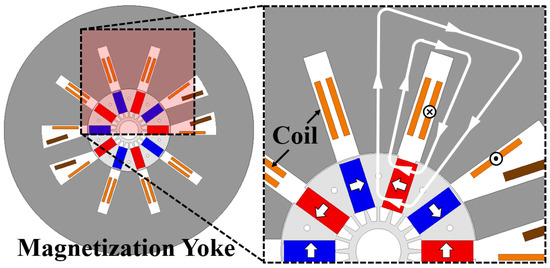
Figure 4.
A 10 pole spoke-type rotor and three-time magnetizer.
Longer PMs can be inserted deeper into the rotor. The magnetic flux path is generated in the magnetizing yoke, as shown in Figure 4. The path of the magnetic flux passing through the inside of the PM is longer than that through the outside. The magnetic reluctance is the same as that in Equation (2); therefore, as the length of the PM increases, the path length of the magnetizing flux generated in the yoke increases, thereby increasing magnetic reluctance [24].
where Rm is the reluctance; l is the length; μ is the permeability; S is the area; N is the number of turns; i is the current; and ϕ is the magnetic flux. Additionally, the saturation of the rotor core and of the magnetizing yoke are high, owing to the application of a large current during magnetization. The magnetic flux passes through the magnetically saturated region and inner side. Due to magnetic saturation, the magnetic permeability of the core in Equation (2) is equal to that of air. Because of this increase in magnetic reluctance, the magnitude of the flux passing through the inner side decreases according to Equation (3) and prevents the smooth magnetization of the inner side, as shown in Figure 5a. Additionally, the distance between the back yoke of the rotor and the PM influences the magnetization performance. Although it has an insignificant effect on the performance of the load operation, as shown in Figure 5a,b, the leakage of the magnetic flux to the back yoke with high magnetic permeability is closer to the PM.
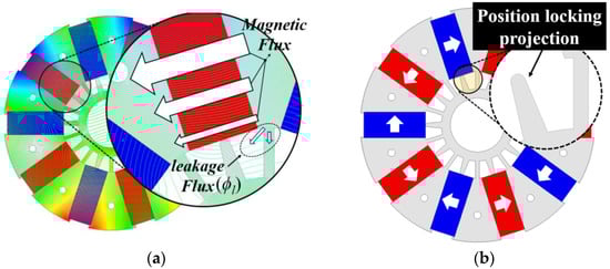
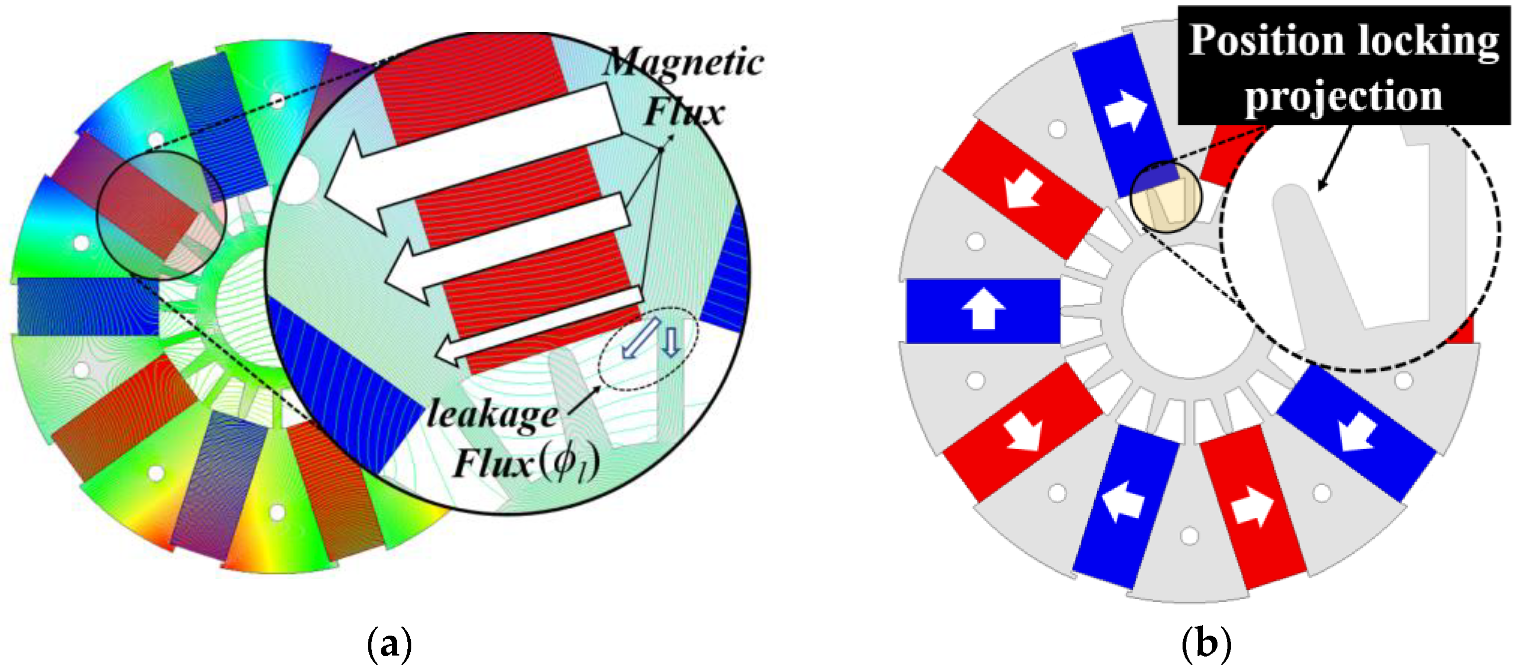
Figure 5.
Factors that decrease magnetization performance. (a) Reduced flux inside the rotor and leakage flux to back yoke, (b) Position locking of projection in the rotor.
Therefore, the inner side of the PM and the back yoke should be separated by a certain distance when considering magnetization. However, if the distance is too large, stiffness may be a problem. Finally, the support structure of the magnet influences magnetization. A position-locking projection, as shown in Figure 5b, is designed to fix the position of the PM in the general spoke-type rotor. However, because the structure also acts as a leakage path for the magnetic flux, it reduces magnetization performance. Factors influencing magnetization are shown as a magnetic equivalent circuit in Figure 6.

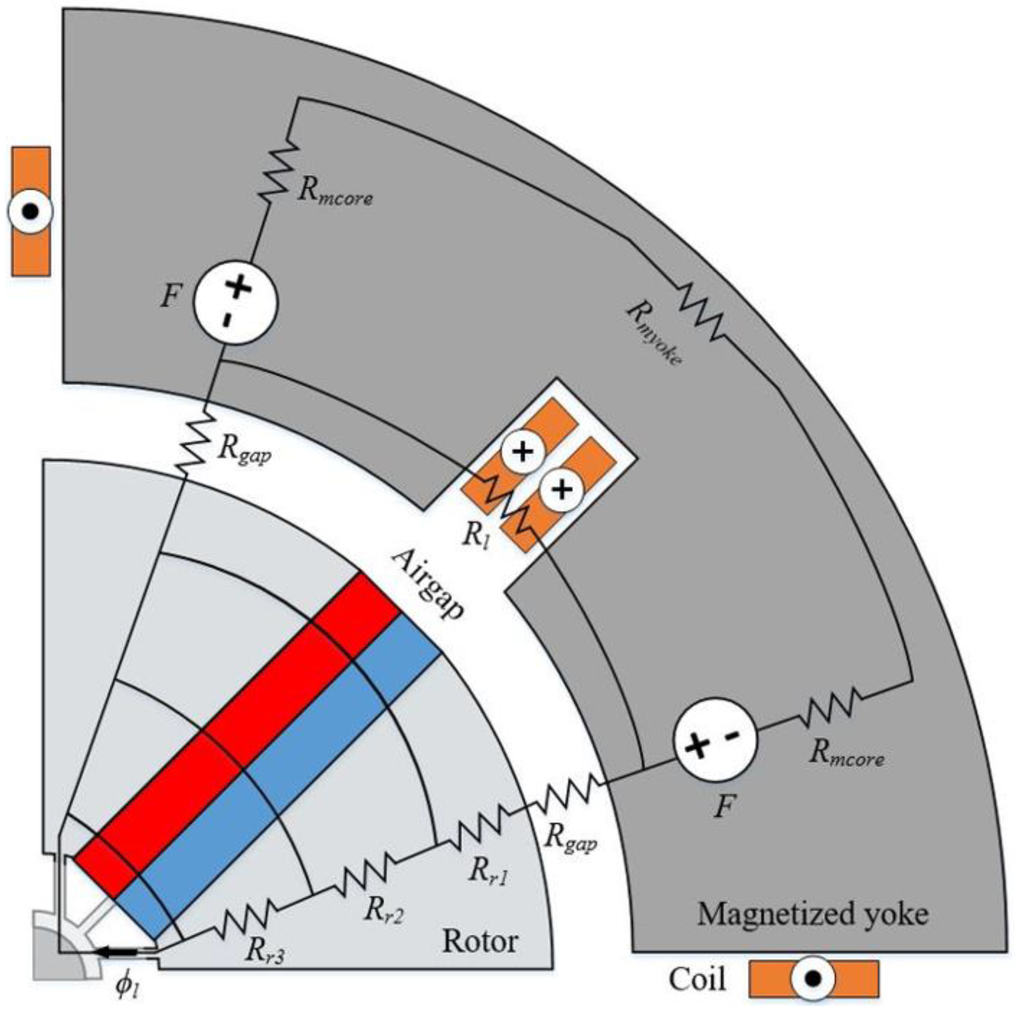
Figure 6.
Magnetic equivalent circuit of the magnetizing yoke and spoke-type rotor.
F is the magnetomotive force of the magnetizing yoke, Rmcore is the reluctance of the magnetizing yoke core, Rmyoke is the reluctance of the magnetizing back yoke, Rl is the reluctance of the coil, Rgap is the reluctance of the air gap, Rr1,r2,r3 are the rotor cores, and ϕl is the leakage flux on the inner bridge side.
During the magnetization of the PM, the flux generated in the yoke passes through the air gap, rotor core, and PM. The magnetizing flux passing through the inside of the rotor must pass through Rr1, Rr2, and Rr3; thus, the magnitude of the magnetizing flux decreases. Moreover, magnetizing the lower part of the rotor is challenging because the leakage flux ϕl is generated by the back yoke of the rotor.
3. Spoke-Type PMSG Design Considering Magnetization
The spoke-type PMSG was designed by considering the factors that influence magnetization, and the design was based on three divided magnetizations. The 500 W class 10-pole, 24 slot PMSG model, and the shape of the yoke are shown in Figure 4. The specifications of the rotor and the magnetizing yoke are listed in Table 1.

Table 1.
Generator target specifications.
To facilitate the magnetization of the inner side, the magnetic reluctance should be decreased and the leakage flux minimized when the magnetic flux passes through the inner side of the rotor and magnet. The magnetic reluctance and leakage flux can be reduced by decreasing the thickness and length of the inner PM. However, performance decreases because of the reduction in PM usage when the size of the PM is minimized using this method. Therefore, the volume of the PM remains unchanged; however, the thickness at the top of the PM has been increased to improve magnetization performance. The rotor shape is shown in Figure 7, and the PM used is trapezoidal. Trapezoidal PMs are advantageous because the projection used to lock the position can also be eliminated, which is a potential path for flux leakage owing to inclination.
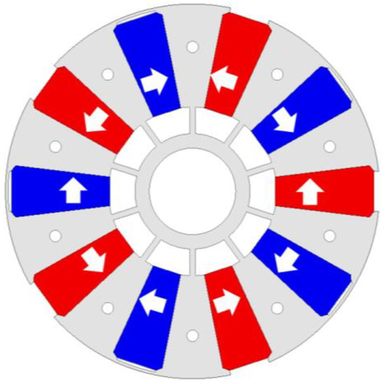
Figure 7.
Rotor shape to improve magnetization performance.
The magnetic resistance increases in line with the thickness of the top of the PM. However, the magnetic flux passing through the top has a shorter path to traverse than the flux in the inner region and passes through the saturated core for the minimum distance. Therefore, the inner side of the rotor can be more easily magnetized. We have validated this claim by simulating the magnetization in the conventional and proposed models using FEA, and the results are shown in Figure 8.
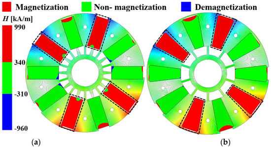
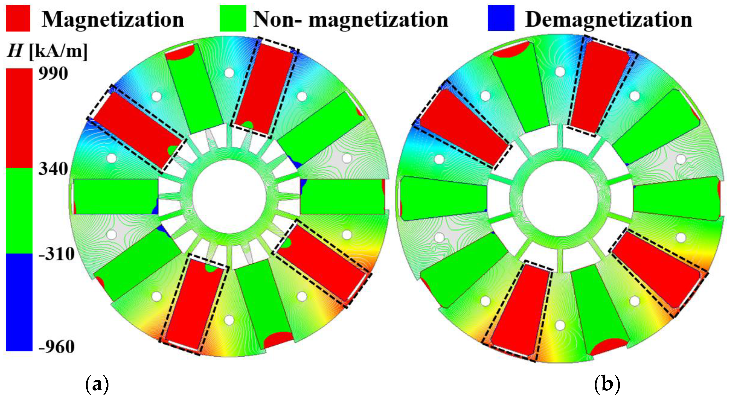
Figure 8.
Comparison of magnetization analysis results. (a) conventional model, (b) proposed model.
Four of the ten magnets are magnetized based on a three-time divided magnetization. The specimens to be magnetized are indicated by dotted black lines. The color bar on the left side of Figure 8 indicates the magnitude of the magnetic field, and divides it into magnetized, non-magnetized, and demagnetized regions based on the initial magnetization curve at room temperature and the B−H curve characteristics of the ferrite magnet used in the model. In the conventional model, an inner non-magnetized area is observed, as shown in Figure 8a, and irreversible demagnetization occurs, which is undesirable. Based on this observation, a design that does not consider magnetization or an excessively large magnetizing flux may influence the previously magnetized PM and cause performance degradation. The magnetization analysis results of the proposed model are shown in Figure 8b. Unlike Figure 8a, which shows the magnetization result of the conventional model, the PM—which is the magnetization target—is completely magnetized. Additionally, the irreversible demagnetization area is very small for other PMs. This is because the inner magnetic resistance is reduced by decreasing the thickness of the bottom of the PM and removing the position locking projection, which is the cause of leakage flux. The performances of the conventional and proposed models are compared under no-load conditions using FEA. The no-load back electromotive force (EMF) of the two models is shown in Figure 9.
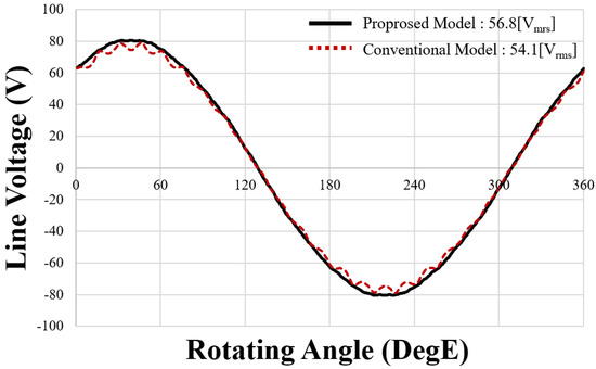
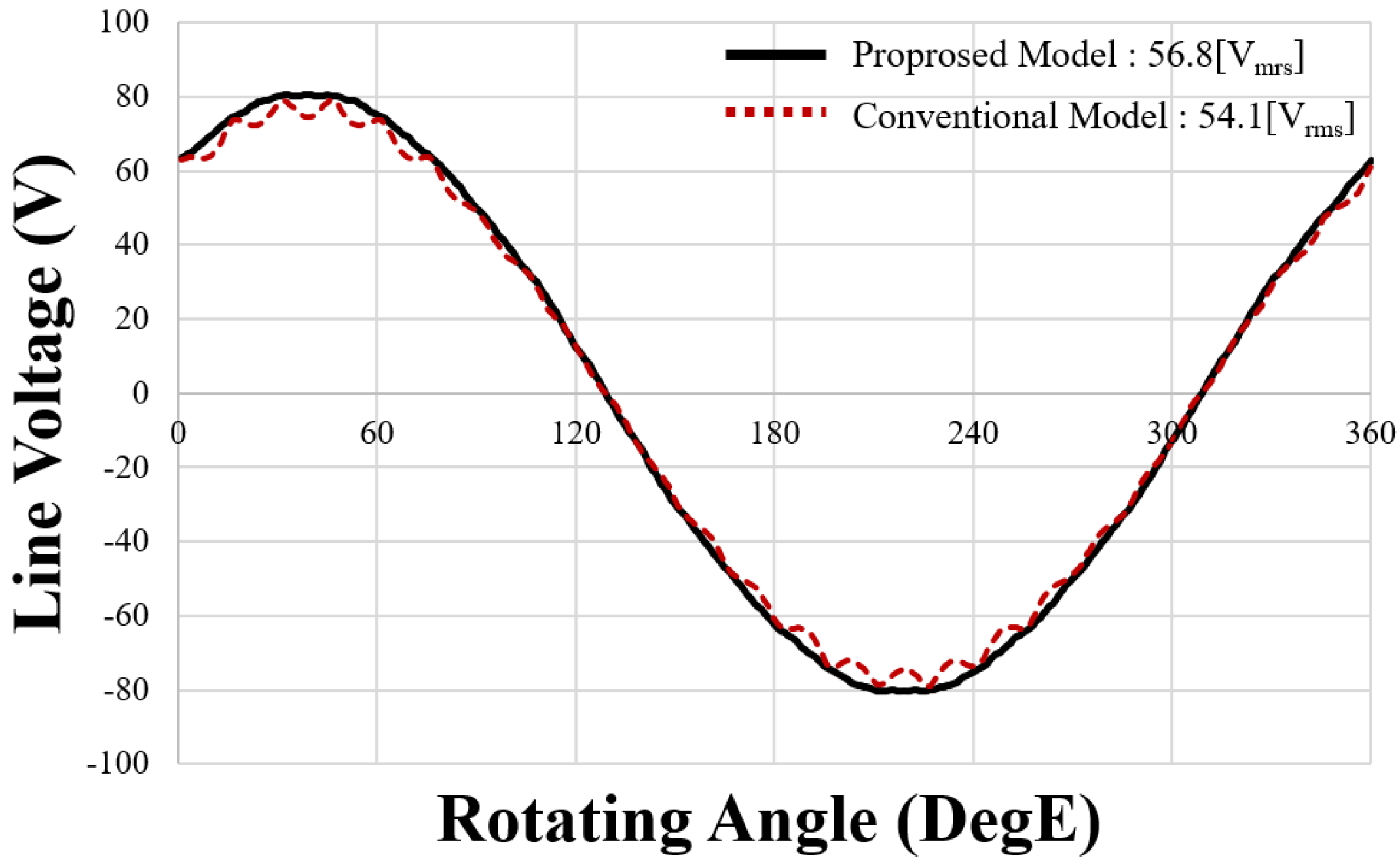
Figure 9.
Comparison of no−load line voltages of the conventional and proposed models.
The counter EMF of the conventional model, shown in Figure 9, is lower than that of the proposed model. Both models have the same magnetizing yoke, magnetizing current, and permanent magnet usage. Hence, this result may be attributed to the formation of undeveloped and demagnetized areas in the conventional model, as shown in Figure 8. However, the proposed model is completely magnetized, and its magnetization performance is improved compared with that of the conventional model.
4. Spoke-Type PMSG Design to Reduce Cogging Torque
The cogging torque performance of a PMSG for wind power generation is crucial because it is directly related to the starting performance. Low capacity wind turbines that can start even at low wind speeds to ensure power generation efficiency are urgently required. Mechanical factors that influence start-up include turbine blade design and shaft friction, whereas electromagnetic factors include the cogging torque of PM generators. Because the starting torque generated by the wind must overcome the cogging torque and mechanical friction, reducing the cogging torque is crucial in the design of wind turbines. Additionally, the cogging torque influences the torque ripple, as well as the vibration and noise of the wind turbines. The torque ripple also increases with an increase in cogging torque, distorting the waveform and rendering the generation of a sine wave challenging, thereby reducing generator efficiency. Generally, a multistage skew is applied to the rotor to reduce the cogging torque; however, it is characterized by poor performance and difficulty in mass production. If the outside of the rotor core is blocked without skew, the productivity increases and the cogging torque decreases. However, the performance considerably degrades owing to magnetic flux leakage.
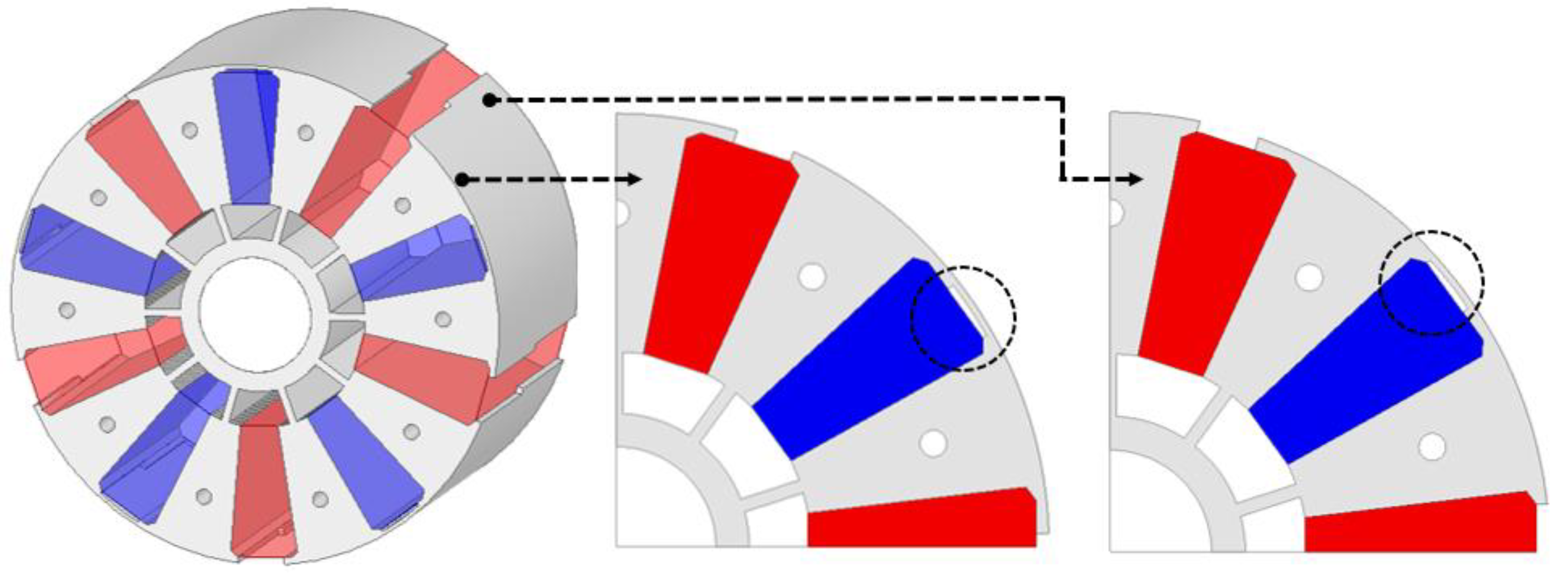
Therefore, as shown in Figure 10, the barrier has been designed asymmetrically, and the bridge has been minimized to propose a cross-stacked rotor shape.

Figure 10.
Rotor barrier asymmetric design and cross-laminated shape.
Unlike the skewed model, the proposed shape improves the productivity compared with the conventional skewed model because the PM and rotor need not be twisted. Moreover, the peak points of the cogging torque offset each other and are reduced when the barrier is designed asymmetrically and the cogging torque is analyzed using FEA, as shown in Figure 11. The conventional spoke-type model uses only a support structure with no outer bridge to prevent output reduction, owing to magnetic flux leakage to the outside of the rotor, as shown in Figure 5b. Therefore, Table 2 compares the performances of the model with the outer bridge removed and the proposed model without load. Therefore, a comparison of the no-load performances of the existing model with no outer bridge and the proposed model to reduce the cogging torque is shown in Table 2. The magnetization in the PM of the conventional model is assumed to be perfect.
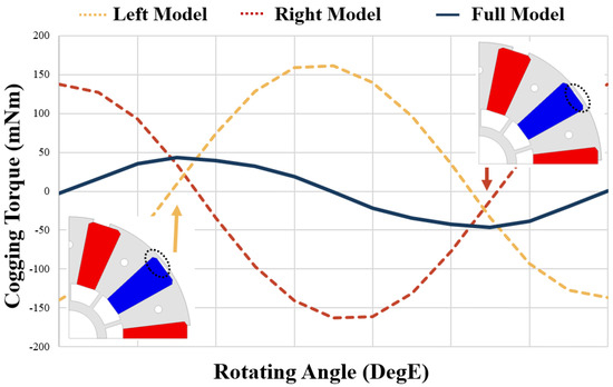
Figure 11.
Cogging torque according to the asymmetric shape of the rotor barrier.
Table 2.
Comparison of no−load performance of the conventional spoke−type model and the proposed model.
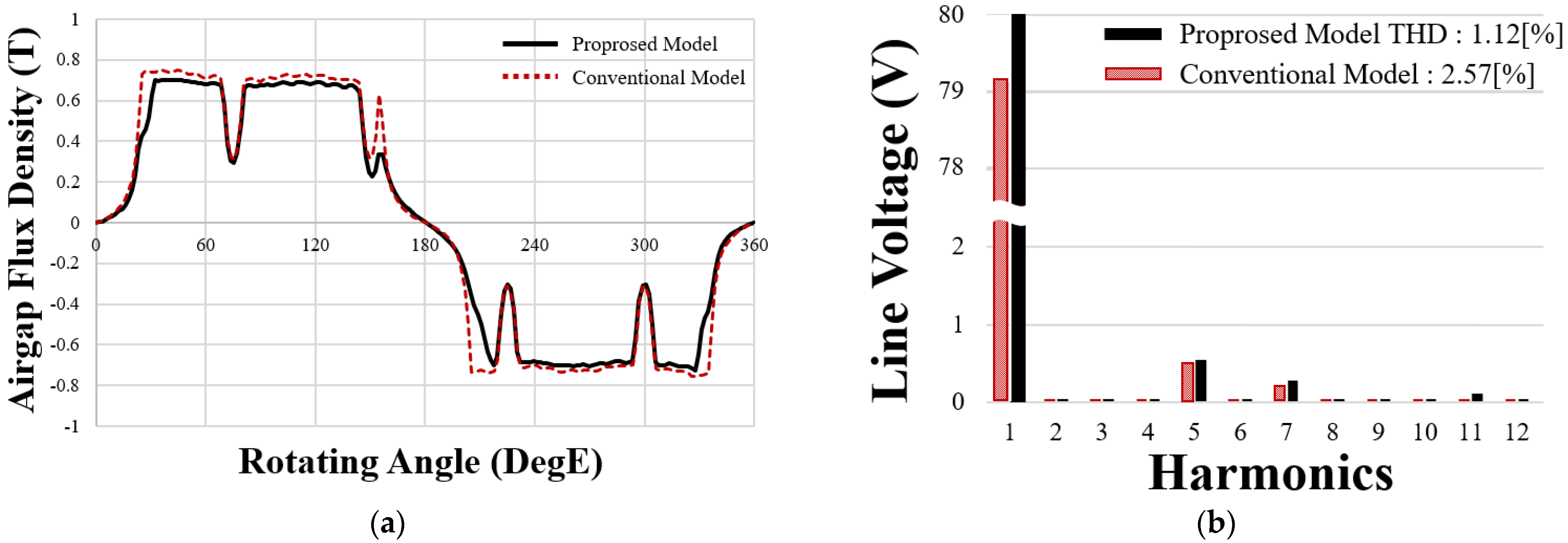
It can be observed that the proposed model has almost the same line voltage as the conventional model. However, the cogging torque has decreased by approximately 80.4% compared with the conventional model, and the total harmonic distortion (THD) has also decreased by 1.45%. As shown in Figure 12a, the cogging torque decreases because the air-gap flux density of the proposed model is more sinusoidal. As shown in Figure 12b, the harmonics of the conventional and proposed models are similar; however, the fundamental wave of the proposed model is larger. It can be observed that the THD is also improved.
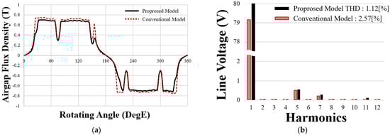
Figure 12.
Comparison of the conventional and proposed models (a) air−gap magnetic flux density, (b) line voltage THD.
Next, the spoke-type generator performance was analyzed for 12, 24, and 36 slots to compare the performance according to the number of stator slots in the proposed rotor shape. The thickness of the stator back yoke was the same, and the tooth thickness was designed by considering the number of slots and saturation. Table 3 compares the performance during the load operation according to the number of stator slots. The efficiency was the best in the 12-slot model; however, the THD failed to satisfy the target specification, and the cogging torque significantly increased compared with the other models. In the case of 36 slots and 24 slots, the main performance did not demonstrate significant differences. Because no significant difference in performance was observed, the 24 slot model was selected for its simpler manufacturability.
Table 3.
Performance comparison according to the number of stator slots.
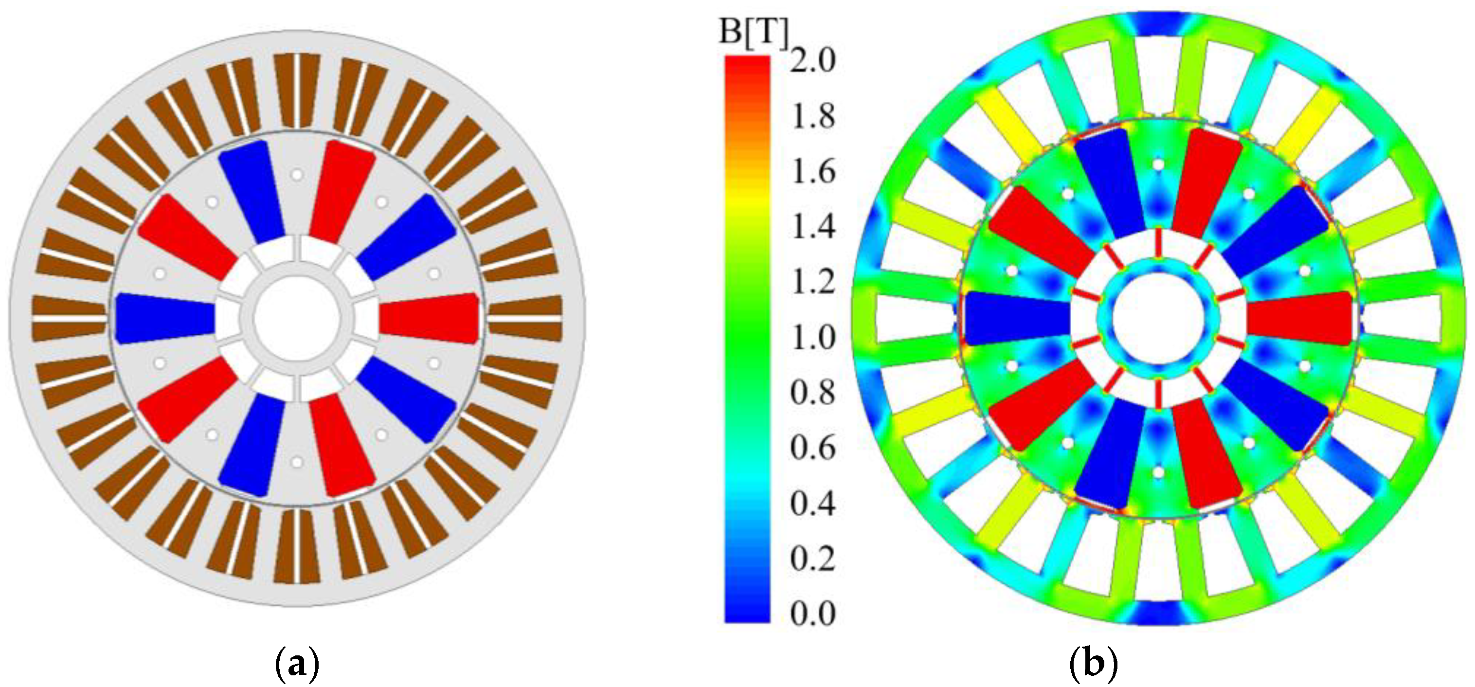
The shape of the final model and the magnetic flux density of the core during the load operation are shown in Figure 13, and a comparison of the performances of the conventional and final model is shown in Table 4. The cogging torque of the conventional model, the final model, and line voltage waveform during the load operation are shown in Figure 14.
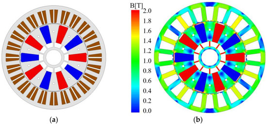
Figure 13.
Final model (a) stator and rotor, (b) core magnetic flux density plot.
Table 4.
Comparison of FEA performance of the conventional and final models.
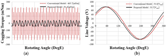
Figure 14.
Comparison of the conventional and proposed models (a) cogging torque, (b) line voltage.
Owing to performance analysis using FEA, the efficiency decreases by approximately 0.2% compared with that of the conventional model; however, the torque ripple and THD are improved. In particular, the cogging torque, which did not satisfy the conventional specifications, decreases significantly. Further, the performance of the basic model in Table 4 is based on the assumption of perfect magnetization, and because of the previous magnetization analysis, the performance of the conventional model is expected to further decrease owing to the occurrence of non-magnetized and demagnetized regions. Conversely, the proposed model is fully magnetized and meets the target specifications in Table 1 for both the no−load and load performances.
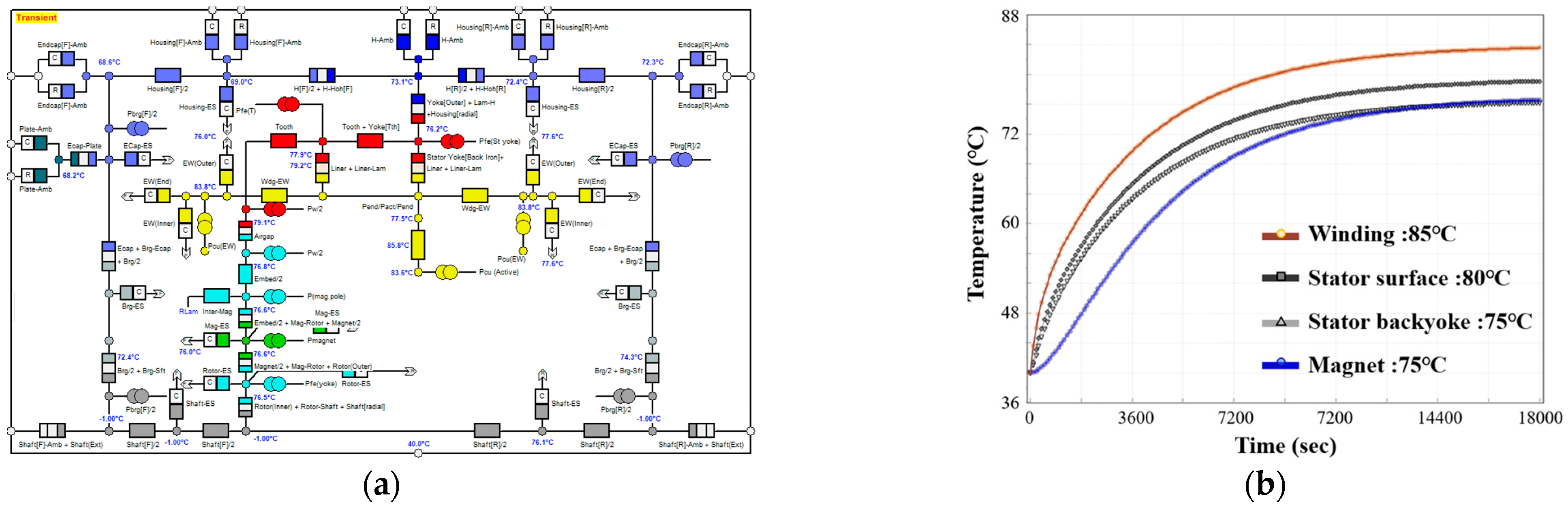
Finally, an irreversible demagnetization analysis was performed considering the characteristics of ferrite PMs. In the case of spoke-type generator ferrite PMs, as shown in Figure 2, they are vulnerable to demagnetization because of their low coercive force compared with that of rare earth magnets, such as Nd and SmCo; therefore, irreversible demagnetization must be reviewed. For an accurate demagnetization analysis, the saturation temperature during the rated operation is validated using a thermal network method, as shown in Figure 15.
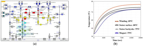
Figure 15.
Thermal characteristics during generator operation (a) thermal network method, (b) temperature saturation graph for each generator part.
This is because high temperatures reduce the residual magnetic flux density of the PM, decreasing the performance of the generator and the coercive force, thus increasing its susceptibility to demagnetization. Considering the saturation temperature, irreversible demagnetization was observed when the magnet temperature was 80 °C and three times the rated current (approximately 23.6 A) was applied. As shown in Figure 16, irreversible demagnetization does not occur even under extreme conditions.
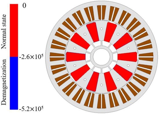
Figure 16.
Final model irreversible demagnetization FEA analysis result.
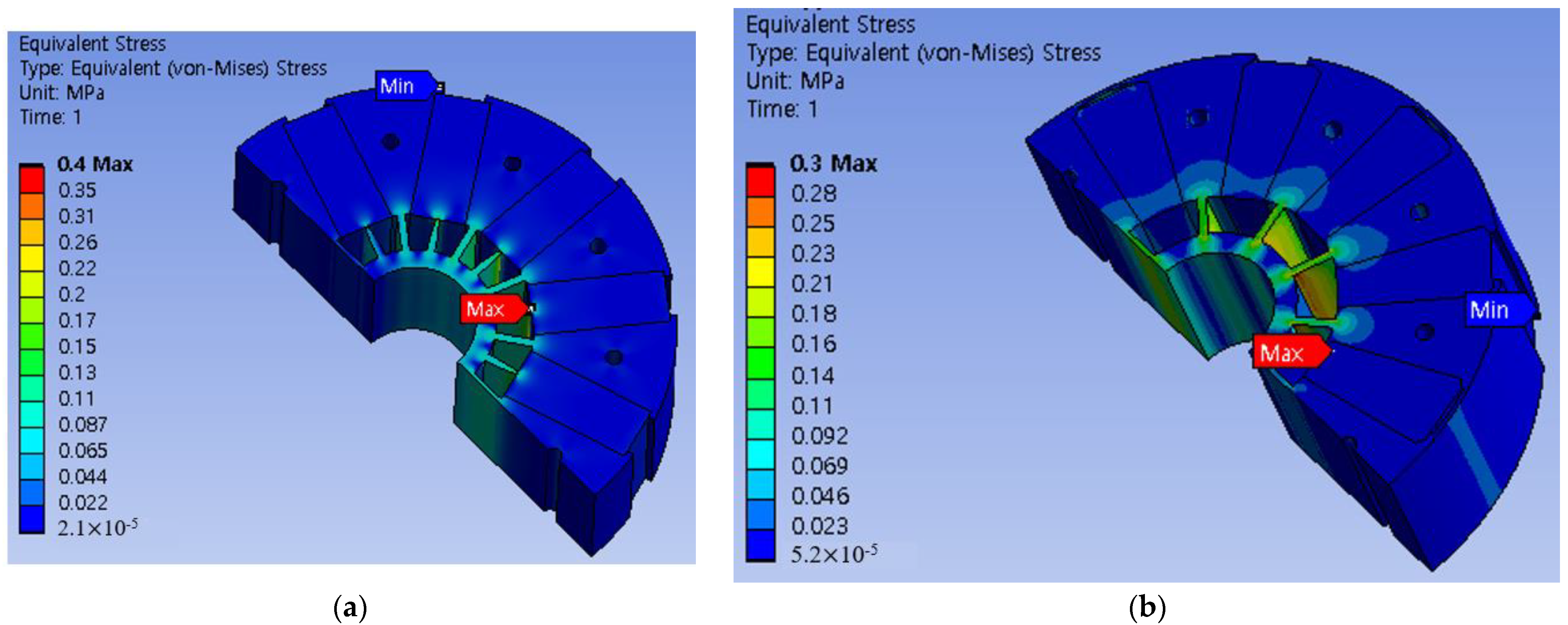
Because the rotor shape was changed to reduce the demagnetization and cogging torque, the mechanical stiffness characteristics at the load driving speed were compared. The stiffness characteristic compares the maximum values of the equivalent stress and the safety factor. The maximum value of the equivalent stress is the maximum stress that can occur in the model, and the safety factor is an index that guarantees structural stability. A comparison of the equivalent stress between the conventional and proposed models is shown in Figure 17. The maximum value of the equivalent stress of the proposed model was approximately 0.3 MPa, which was slightly improved compared with that of the conventional model; however, the maximum value of the equivalent stress of both models was low. This is because the operating speed of this model was low at 350 rpm, and the safety factor of both models was 15, confirming that there is no problem with the mechanical stiffness.

Figure 17.
Comparison of maximum equivalent stress values during load operation (a) conventional model, (b) proposed model.
5. Performance Test and Results
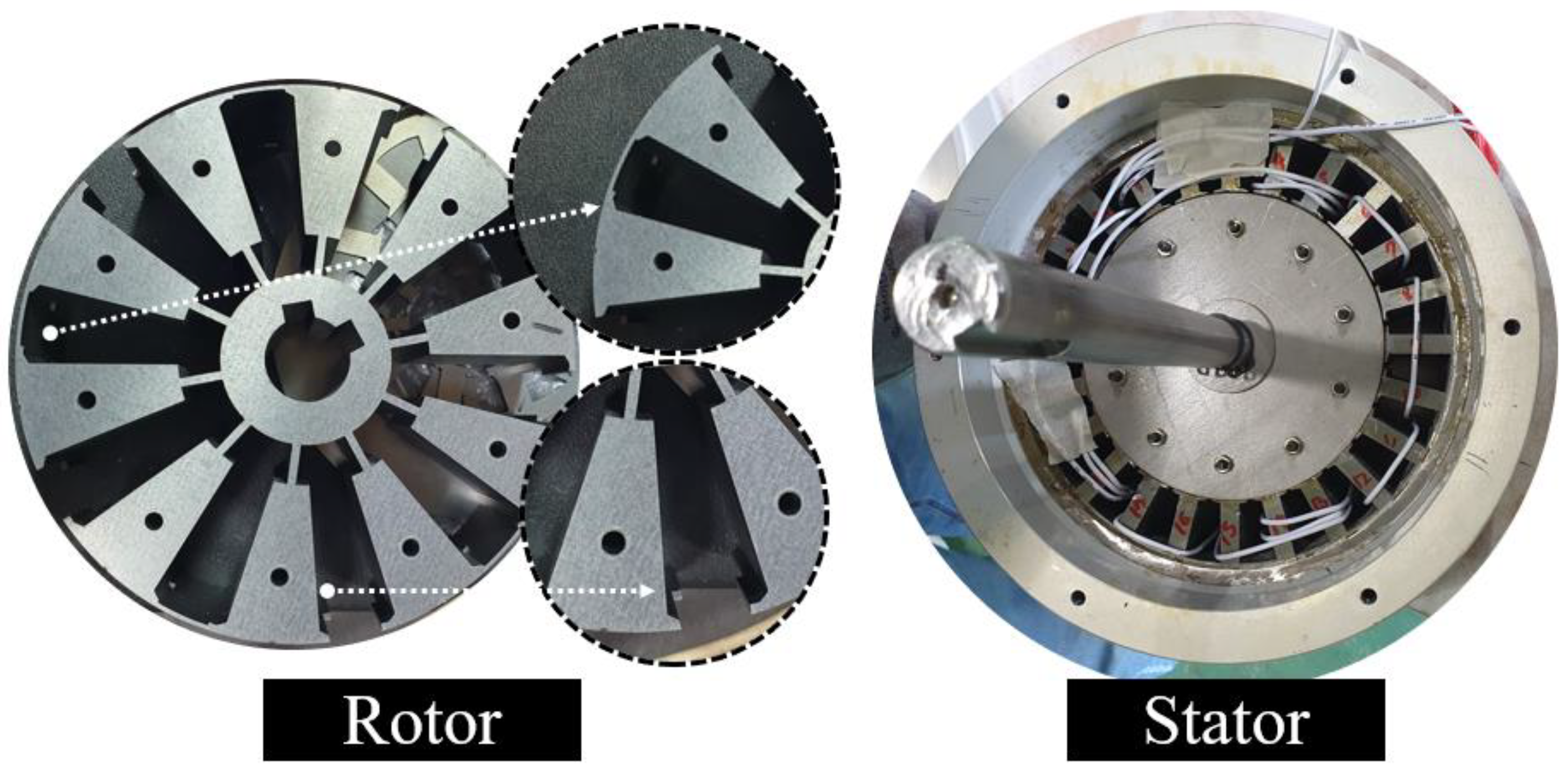
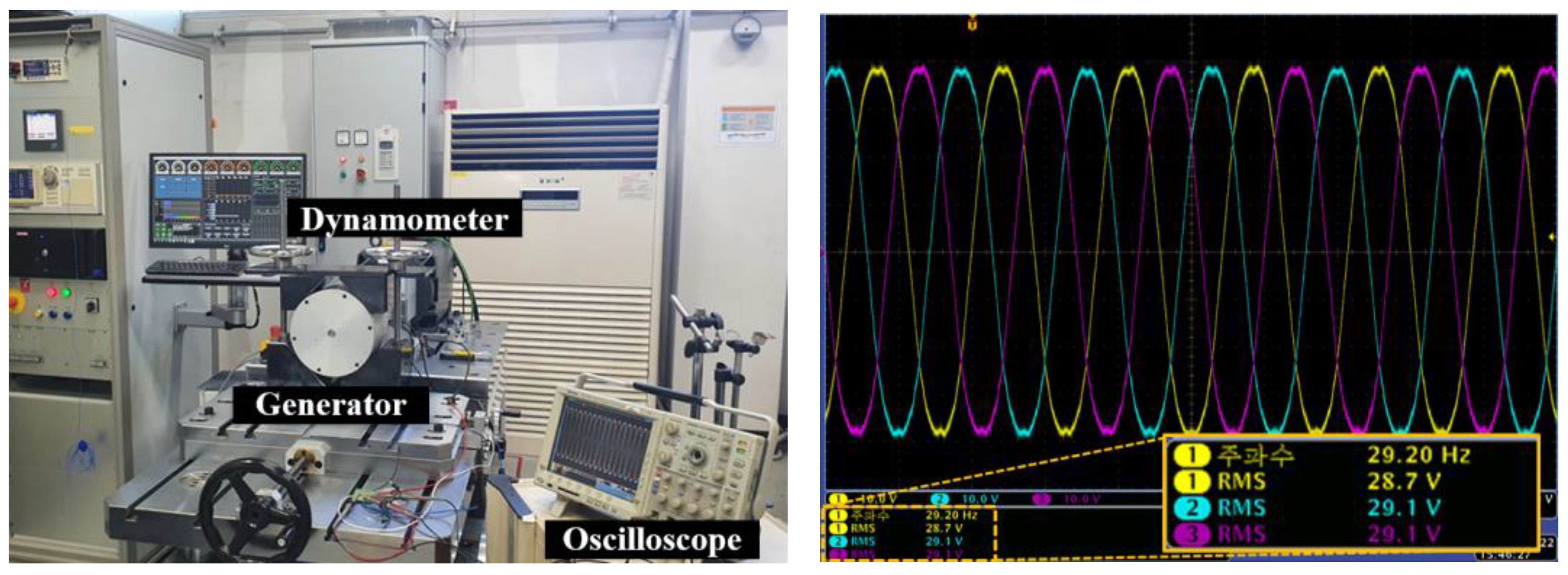
Prototypes were manufactured, and performance tests were conducted to validate the proposed design. The prototype is shown in Figure 18, a comparison of the test environment and measurement waveform is shown in Figure 19, and a comparison of the FEA and test results is shown in Table 5.
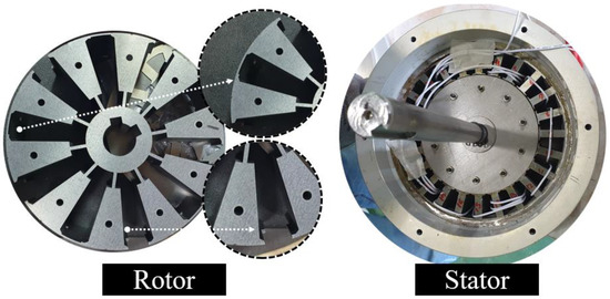
Figure 18.
Image of the prototype generator core.
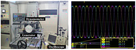
Figure 19.
Test and no-load BEMF measurement.
Table 5.
Comparison of FEA and test results.
Performance tests were performed at ambient temperature. Most of the performance results measured via the load test were similar to the FEA results. Although the efficiency slightly decreased owing to the increase in winding resistance and current, the copper loss increased. However, the target performance was satisfied, and the design feasibility was validated through a comparison with the analysis results.
6. Conclusions
A rotor design study was conducted to improve the magnetization and starting performance of a low capacity wind-turbine. To improve the magnetization performance, magnetization–related factors, the magnetization yoke, and the magnetic equivalent circuit were analyzed. Accordingly, the rotor shape variable selection and magnetization performance improvement design were performed, and the magnetization performance improvement was validated through FEA. To improve maneuverability, an additional design was developed to reduce the cogging torque, which is an electromagnetic factor. The existing skew application method has poor manufacturability. The cogging torque was reduced while increasing productivity by cross-laminating barriers with asymmetric barriers. The final model was selected, and its performance was compared with that of the conventional model. The analysis confirmed that all the target performance criteria were satisfied, and the cogging torque as well as the THD were improved. Because the best performance of the conventional model was obtained when magnetization was complete, the performance can be further decreased owing to the occurrence of an unattached area when magnetized with the same yoke. Finally, the design was verified through prototype production and testing of the design model.
The results of this study can contribute to the analysis of generator characteristics and the optimal design for low capacity wind turbines, which have recently attracted increasing attention. Additionally, these results are expected to be applied to various fields, such as motors and magnetization research using spoke-types and generators.
Author Contributions
Conceptualization, D.-H.K.; methodology, W.-H.K.; software, D.-H.K.; validation, D.-H.K.; formal analysis, H.-J.P.; investigation, D.-H.K.; resources, J.L.; data curation, D.-H.K.; writing—original draft preparation, D.-H.K.; writing—review and editing, K.-D.L. and J.L.; visualization, H.-J.P. and W.-H.K.; supervision, K.-D.L. All authors have read and agreed to the published version of the manuscript.
Funding
This study was supported by the Industrial core technology development project (No. 20012518) and in part by the Technology Innovation Program (No. 20020409) funded by the Ministry of Trade, Industry & Energy (MOTIE), Korea.
Data Availability Statement
Not applicable.
Conflicts of Interest
The authors declare no conflict of interest.
References
- Ko, K.; Jang, S.; Park, J.; Cho, H.; You, D.-J. Electromagnetic Performance Analysis of Wind Power Generator w With Outer Permanent Magnet Rotor Based on Turbine Characteristics Variation Over Nominal Wind Speed. IEEE Trans. Magn. 2011, 47, 3292–3295. [Google Scholar] [CrossRef]
- Gu, Y.; Huang, Y.; Wu, Q.; Li, C.; Zhao, H.; Zhan, Y. Isolation and Protection of the Motor-Generator Pair System for Fault Ride-Through of Renewable Energy Generation Systems. IEEE Access 2020, 8, 13251–13258. [Google Scholar] [CrossRef]
- Fang, Y.; Jia, K.; Yang, Z.; Li, Y.; Bi, T. Impact of Inverter-Interfaced Renewable Energy Generators on Distance Protection and an Improved Scheme. IEEE Trans. Ind. Electron. 2019, 66, 7078–7088. [Google Scholar] [CrossRef]
- Zamani, M.H.; Riahy, G.H.; Abedi, M. Rotor-Speed Stability Improvement of Dual Stator-Winding Induction Generator-Based Wind Farms by Control-Windings Voltage Oriented Control. IEEE Trans. Power Electron. 2015, 31, 5538–5546. [Google Scholar] [CrossRef]
- Yang, X.; Patterson, D.; Hudgins, J. Permanent magnet generator design and control for large wind turbines. In Proceedings of the 2012 IEEE Power Electronics and Machines in Wind Applications (PEMWA 2012), Denver, CO, USA, 16–18 July 2012; pp. 1–5. [Google Scholar]
- Lee, J.; Seo, G.; Mun, J.; Park, M.; Kim, S. Thermal and Mechanical Design for Refrigeration System of 10 MW Class HTS Wind Power Generator. IEEE Trans. Appl. Supercond. 2020, 30, 5201905. [Google Scholar] [CrossRef]
- Chen, Y.; Pillay, P.; Khan, A. PM wind generator comparison of different topologies. In Proceedings of the 2004 IEEE Industry Applications Conference, Seattle, WA, USA, 16–18 October 2004; pp. 1405–1412. [Google Scholar]
- Khan, M.A.; Pillay, P.; Malengret, M. Impact of direct-drive WEC Systems on the design of a small PM wind generator. In Proceedings of the 2003 IEEE Bologna Power Tech Conference Proceedings, Bologna, Italy, 23–26 June 2003; p. 7. [Google Scholar]
- Wang, F.; Qingming, H.; Jianlong, B.; Jian, P. Study on control system of low speed PM generator direct driven by wind turbine. In Proceedings of the 2005 International Conference on Electrical Machines and Systems (ICEMS 2005), Nanjing, China, 27–29 June 2005; pp. 1009–1012. [Google Scholar]
- Wu, Z.; Dou, X.; Chu, J.; Hu, M. Operation and Control of a Direct-Driven PMSG-Based Wind Turbine System with an Auxiliary Parallel Grid-Side Converter. Energies 2013, 6, 3405–3421. [Google Scholar] [CrossRef]
- Kou, S.; Kou, Z.; Wu, J.; Wang, Y. Modeling and Simulation of a Novel Low Speed High-Torque Permanent Magnet Synchronous Motor with Asymmetric Stator Slots. Machines 2022, 10, 1143. [Google Scholar] [CrossRef]
- Tahanian, H.; Aliahmadi, M.; Faiz, J. Ferrite Permanent Magnets in Electrical Machines: Opportunities and Challenges of a Non-Rare earth Alternative. IEEE Trans. Magn. 2020, 56, 900120. [Google Scholar] [CrossRef]
- Zhu, X.; Wang, L.; Chen, Y.; Chen, L.; Quan, L. A Non-Rare Earth Doubly Salient Flux Controllable Motor Capable of Fault-Tolerant Control. IEEE Trans. Magn. 2015, 51, 8111204. [Google Scholar] [CrossRef]
- Barcaro, M.; Bianchi, N. Interior pm machines using ferrite to replace rare earth surface PM machines. IEEE Trans. Ind. Appl. 2014, 50, 979–985. [Google Scholar] [CrossRef]
- Fasolo, A.; Alberti, L.; Bianchi, N. Performance comparison between switching-flux and IPM machines with rare earth and ferrite PMs. IEEE Trans. Ind. Appl. 2014, 50, 3708–3716. [Google Scholar] [CrossRef]
- Morimoto, S.; Ooi, S.; Inoue, Y.; Sanada, M. Experimental Evaluation of a Rare Earth-Free PMASynRM with Ferrite Magnets for Automotive Applications. IEEE Trans. Ind. Electron. 2014, 61, 5749–5756. [Google Scholar] [CrossRef]
- Obata, M.; Morimoto, S.; Sanada, M.; Inoue, Y. Performance of PMASynRM with Ferrite Magnets for EV/HEV Applications Considering Productivity. IEEE Trans. Ind. Appl. 2014, 50, 2427–2435. [Google Scholar] [CrossRef]
- Jeong, M.J.; Lee, K.B.; Pyo, H.J.; Nam, D.W.; Kim, W.H. A Study on the Shape of the Rotor to Improve the Performance of the Spoke Type Permanent Magnet Synchronous Motor. Energies 2021, 14, 3758. [Google Scholar] [CrossRef]
- Kim, K.; Park, M.; Kim, H.; Chai, S.; Hong, J. Estimation of Rotor Type Using Ferrite Magnet Considering the Magnetization Process. IEEE Trans. Magn. 2016, 52, 8101804. [Google Scholar] [CrossRef]
- Seol, H.; Jeong, T.; Jun, H.; Lee, J.; Kang, D. Design of 3-Times Magnetizer and Rotor of Spoke Type PMSM Considering Post-Assembly Magnetization. IEEE Trans. Magn. 2017, 53, 8208005. [Google Scholar] [CrossRef]
- Lee, S.G.; Bae, J.; Kim, W. Design Process of Spoke Type Permanent Magnet Synchronous Motor Considering Magnetization Performance. IEEE Trans. Appl. Supercond. 2020, 30, 5205706. [Google Scholar] [CrossRef]
- Kim, D.-H.; Kim, S.-Y.; Song, S.-W.; Lee, J.; Kim, W.-H. Spoke type Permanent Magnet Synchronous Generator Design considering Magnetizing and Cogging Torque. In Proceedings of the 2022 IEEE Energy Conversion Congress and Exposition (ECCE), Detroit, MI, USA, 9–13 October 2003; pp. 1–6. [Google Scholar]
- Hanselman, D. Magnetic modeling. In Brushless Motors: Magnetic Design, Performance, and Control of Brushless DC and Permanent Magnet Synchronous Motors; E-Man Press LLC: New York, NY, USA, 2012; pp. 16–18. [Google Scholar]
- Kim, D.-H.; Kim, K.S.; Yang, I.-J.; Lee, J.; Kim, W.-H. Alternative Bridge Spoke Permanent Magnet Synchronous Generator Design for Wind Power Generation Systems. IEEE Access 2021, 9, 152819–152828. [Google Scholar] [CrossRef]


Disclaimer/Publisher’s Note: The statements, opinions and data contained in all publications are solely those of the individual author(s) and contributor(s) and not of MDPI and/or the editor(s). MDPI and/or the editor(s) disclaim responsibility for any injury to people or property resulting from any ideas, methods, instructions or products referred to in the content. |
© 2023 by the authors. Licensee MDPI, Basel, Switzerland. This article is an open access article distributed under the terms and conditions of the Creative Commons Attribution (CC BY) license (https://creativecommons.org/licenses/by/4.0/).