Abstract
The evolution of power generation brings about extensive changes in other parts of the grid, especially in the transmission and distribution components. Within the scope of the Internet of Energy (IoE), electric power flows more flexibly between different parts of the grid. DC power will play an essential role in IoE. Decentralized photovoltaic panels, energy storage, electric vehicle charging stations, and data centers are some of the significant components of future grids dealing with DC power. As a result, power transformers must be appropriately modified to manage power among the different parts of the grid. A power electronic transformer (PET), also known as a solid-state transformer (SST) or smart transformer (ST), is a solution enabling a power grid to deal with this growing complexity. ROMAtrix, as a matrix-converter-based ST, is a developing project targeting future power grids. ROMAtrix realizes the application of a medium voltage (MV) transformer using commercially available power electronic semiconductors. Due to the distinctive features of ROMAtrix and a high number of switches, the implementation of the control system using a single control board is highly demanding. This paper aims to illustrate the implementation, on a field-programmable gate array (FPGA), of pulse width modulation (SVMPWM) applied to the ROMAtrix, considering specific switching patterns. The proposed switching procedure was simulated with PLECS and validated with the hardware-in-the-loop using the OPAL-RT solver.
1. Introduction
The growing trend towards distributed generation is transforming electric power systems. The advantages provided by distributed renewable energy, such as reduction of losses in the transmission lines, lower greenhouse effect, cost-effective performance, improved power quality, and increased reliability, are some of the motivations for shifting the pattern from centralized generation to micro-grids, which are based on distributed generators and local loads [1,2]. However, the implementation of these advanced grids is associated with various challenges. Microgrid protection is the most crucial factor to take into consideration. Due to the presence of distributed energy resources (DERs) in microgrids, the direction of the power flow and the magnitude of fault current vary, resulting in a more complicated protection scheme than in traditional grids [3]. The presence of DC grids, both on the generation and the consumer sides, is the other challenge of modern microgrids. Due to the intermittent nature of renewable resources, energy storage systems (ESS), such as DC components, are considered in the grid design. The presence of ESS requires the feasibility of bidirectional energy flow in the grid. In addition, resources such as photovoltaic (PV) systems and fuel cells inherently generate DC power. On the load side, LED lighting, electric vehicle charging stations, data centers, and electronic loads are the major consumer of DC power. Traditional transformers have proved to be entirely inadequate in the face of the ongoing changes to power grids.
The power electronic-based concept named smart transformers (ST), otherwise known as solid-state transformers (SST) or power electronic transformers (PET), are promising solutions that can process any form of power. STs are able to fulfill the requirements of various generators and loads in the power grids [4]. In addition to enhanced flexibility and controllability, STs facilitate ancillary services in the grid [5,6]. The most common ST strategy is multistage DC/AC conversion and vice versa [7,8].
The traditional line frequency transformers have some undeniably remarkable features, such as low production costs, relatively high efficiency, and high reliability. However, they can only perform AC/AC conversion, whilst the need for DC source availability in future grids is a decisive factor [9]. According to [10], by 2030, renewable energies will account for 36% of the world’s energy share. This high penetration of the DC grid requires more flexible power management. The advantages of traditional transformers have motivated some researchers to use them with STs, to obtain the benefits of both transformers and cope with the grid growth [11]. In these so-called hybrid transformers, a major part of the power flows through the traditional transformers and only a small fraction flows through the ST. Although traditional transformers offer higher reliability, in the case of any unplanned outages, it can take up to 24 months to receive a replacement transformer [12,13]. In [14], it is mentioned that with an EV penetration of 50%, traditional transformers’ life is reduced by 200–300% relative to nonpenetration with uncontrolled charging. That is why STs were reported as one of the top ten emerging technologies by the Massachusetts Institute of Technology (MIT) Technology Review [15]. According to [16], in a grid with AC and DC players, ST is only 30% more expensive than a traditional transformer and its associated power electronic equipment. However, STs’ advantages justify this additional cost. In addition to the extra flexibility and functionality, the smaller footprint of ST can lead to financial advantages. In Ref. [17], it is mentioned that ST could be a much better option in crowded city centers, where space is lacking and expensive. In transportation such as planes, trains, and ships, smaller volumes and lighter weights are crucial. In addition, [18] mentions that the modularity of ST would enable moving them with a truck as an emergency replacement for traditional transformers. In contrast to traditional transformers, SSTs do not use oil in their structure, making them environmentally friendly and safer in terms of fires or explosion. Finally, a drastic reduction in SiC devices is expected [19,20], which could change the status quo in favor of STs.
Smart grid (SG) technology optimizes a grid’s performance by combining power systems and information and communication technology (ICT). That is, SG makes the power grid more flexible, efficient, and economical [21].
Having evolved from the smart grid, the internet of energy (IoE), also known as energy internet (EI), is another promising topic in power systems [22,23]. IoE eliminates the limits and shortcomings of the smart grids and integrates further infrastructure such as transportation systems and natural gas networks into power systems [24]. Renewable energy resources play a more dominant role in IoE than smart grids [25]. In addition, in grids based on the IoE, bidirectional energy transmission enables users to complete peer-to-peer transactions [26]. Taking these accelerating changes into account, future power transformers must process energy in a complex manner, while assuring a flexible and reliable power flow. As mentioned before, conventional power transformers will be unable to handle these forthcoming changes.
Different classifications for STs have been proposed in the literature [27,28]. Figure 1 presents different topologies of ST based on the number of AC/DC or DC/AC conversion stages [29], namely single-stage, two-stage, and three-stage ST transformers. Terminals for high-voltage alternating current (HVAC), high-voltage direct current (HVDC), low-voltage alternating current (LVAC), and low-voltage direct current (LVDC) are also indicated in Figure 1. Each topology has its pros and cons [30]; for example, a lower weight, smaller footprint, lower price, and fewer semiconductors give the single-stage topology (Figure 1a) distinct advantages over two and three-stage topologies. Nevertheless, due to the lack of a DC-link, disturbances of one side can easily be transferred to the other side. A lack of interaction with local DC components of the grid, such as DC loads, transmissions, renewables, and battery storage is another shortcoming of these topologies. Two single-stage topologies based on a full-bridge converter and flyback converter are presented in [31]. Depending on the location of the isolation transformer, the two-stage ST has two different structures. In the first structure, shown in Figure 1b, high-voltage AC is converted into low-voltage DC and then into low-voltage AC [32]. Meanwhile, in the second structure, illustrated in Figure 1c, high-voltage AC is converted into high-voltage DC and then inverted into low-voltage AC. Two-stage topologies offer more functionality in comparison to single-stage topologies, such as interacting with DC components of the grid, decoupling the input and the output of the converter, and compensating for reactive power. Two-stage topologies, however, have a more complex control in comparison to single-stage topologies. In addition, obtaining zero voltage switching in these topologies is challenging, resulting in a reduced efficiency.
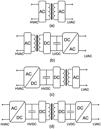
Figure 1.
Classification of STs based on conversion stages, (a) single-stage ST, (b,c) two-stage ST, and (d) three-stage ST.
Three-stage STs, as presented in Figure 1d, comprise an AC/DC conversion followed by DC/DC and DC/AC conversion. There is an isolation transformer in the DC/DC stage. This topology has two DC links, one on the high-voltage side and the other on the low-voltage side, giving the transformer a higher degree of flexibility. All features of the previous topologies are achievable with this topology, making it the most favorable ST topology for the grid. Needless to say, the presence of three stages in this topology gives rise to higher costs and losses.
Due to the limited availability of commercially available power electronic switches and magnetic components, building an ST adaptable to high voltage (HV) and medium voltage (MV) grids requires a series of connections of several modules. Modular multilevel converters (MMC) and cascaded H-bridge converters (CHB) are the two common methods used to cope with higher voltage levels [33]. However, these two topologies suffer from serious disadvantages [34]. Both topologies require too many components, which is responsible for their lower reliability, higher cost, and complex control. CHB requires many isolated resources, provided by transformers and power electronic devices. Compared to conventional inverters, an MMC requires large capacitance values. In addition, unbalanced capacitor voltages directly affect the output voltages’ quality. Thus, it is essential to devise a strategy to ensure an equal voltage level in capacitors, which brings extra complexity and cost [35,36].
Due to their lack of capacitors, matrix converters do not deal with the control challenges of CHB and MMC. Eliminating the capacitors and their related components (such as pre-charge resistors in parallel with a thyristor) leads to a smaller footprint, affordable price, and enhanced reliability. Matrix converters can also control the input power factor without using a power factor correction (PFC) stage, which is an inevitable part of conventional converters. Several ST topologies based on matrix converters have been proposed in the literature. The topology proposed in [37] uses 144 semiconductor switches and nine transformers to convert MV to LV. The high number of elements in this topology is its main disadvantage, which results in a higher cost and complicated control. Moreover, the switches must tolerate phase-to-neutral voltage when they are turned off. The topology studied in [38] and [39] is not designed for a MV grid and the switches cannot tolerate higher voltage levels. The ST introduced in [40] is a modular multilevel matrix converter and was designed for high-voltage AC substations. However, in contrast to the nature of matrix converters, it utilizes numerous cell capacitors in its structure. The same problem is seen in the matrix converter presented in [41], and this converter requires a capacitor in its structure.
ROMAtrix, an ongoing ST project, was first introduced in [42] and aims to remove ST’s limitations in medium voltage grids. Due to the lack of capacitors in the structure, it does not suffer from the problems associated with capacitors. To comply with the perspective of the IoE, in future works, ROMAtrix will be developed into a multi-port converter with an extra port, to include DC grids in its design. However, the multi-port design of ROMAtrix is beyond the scope of this paper. The main focus of this paper is implementing space vector modulation pulse width modulation (SVMPWM) control of ROMAtrix on a control board, which utilizes the field-programmable gate array (FPGA). Due to the unique characteristics of the ROMAtrix, its switching pattern differs from other matrix converters. The switching procedure is validated through a real-time hardware-in-the-loop (HIL) system. The rest of the current manuscript is organized as follows: the second section briefly reviews the performance principles of ROMAtrix. The switching procedure of the converter is presented in the third section. The simulation results, SVMPWM implementation on FPGA, and HIL validation are illustrated in the fourth and fifth sections. Finally, the sixth section concludes the paper.
2. Performance Principles of ROMAtrix
The ROMAtrix topology, which consists of three identical modules, is demonstrated in Figure 2. The modules are indirect matrix converters (IMC) isolated by a medium frequency transformer (MFT). Each module belongs to one of the phases in the input/output. There are three legs on each side of the modules. One of the legs connects the module to the input/output phases; the other two legs connect the module to other modules. Every leg used in the modules is made up of two bidirectional switches, which means four semiconductor switches exist in each leg. A detailed scheme of the switches is shown in Figure 2. Using bidirectional switches enables ROMAtrix to guarantee complete control over the bidirectional power flow. The proposed topology would handle MV in the grid utilizing commercially available power electronics semiconductors. Therefore, switching arrangements that apply voltage values beyond the maximum rating of the semiconductors and transformers must be avoided.
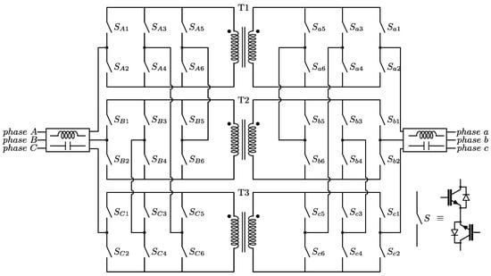
Figure 2.
ROMAtrix topology.
Given that the left side of the transformer is the MV side, in each instant, the phase-to-phase input voltage must be tolerated by two transformers in series. Similarly, the voltage applied to an open switch must be shared with another switch in series. In addition, there are some other common rules for the inverters that are taken into consideration. More specifically, in conventional two-stage converters, the input side is a rectifier, in which just two out of three phases conduct in a specific time interval, while the third phase is disconnected. Similarly, in the ROMAtrix, the converter’s input side behaves as a current rectifier (CSR); thus, in any interval, only two of the phases are responsible for transferring power from the input to the output. Furthermore, short-circuiting between phases must be avoided on the input side. In conventional voltage source inverters (VSI), a DC-link capacitor interconnects the input and output. Thus, switching states that make short circuits across the capacitor must be avoided. Due to the inductive nature of generic loads, switching states leading to an open circuit at the output should also be avoided.
In matrix converters, there is no DC-link capacitor, so by appropriate switching of the input phases, an instantaneous DC-link is created between the input and the output. This DC-link is called a virtual DC-link, implying the lack of a physical capacitor in the system. Here, the output-side converter acts as a VSI, and the same rules must be observed. Despite the high number of switches, these constraints limit switching states and facilitate control of the converter. Figure 3 depicts the two permissible switching states of the ROMAtrix. In the first state, Figure 3a, since the power flow is from the left to the right of the converter, input phase A and phase B create a virtual DC-link. The polarity of this DC-link is indicated by [+] and [−]. In addition, on the output side, such as in a conventional VSI, the phases are connected either to the positive or negative pole of this DC-link.
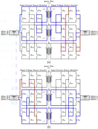
Figure 3.
Examples of the permissible switching states: (a) power flow from grid “ABC” to “abc” and (b) power flow from grid “abc” to “ABC”.
However, in Figure 3b, due to the direction of the power flow, the converter’s right side, grid “abc”, transfers power to its left side, grid “ABC.” As a result, in this case, the right side of the converter acts as CSR, and the left side acts as a VSI.
A qualitative comparison among three grid-scale converters, namely solid-state power substation (SSPS) [43], universal and flexible power management (UNIFLEX PM) [44,45], and ROMAtrix is provided in Table 1. The superiority of the ROMAtrix over the two other converters is the lower number of switches used in its structure. In addition, unlike UNIFLEX PM, ROMAtrix does not have numerous DC-link stages containing electrolyte capacitors in its topology. The only shortcoming of the ROMAtrix in comparison to the two other topologies is that it is not scalable.

Table 1.
Comparing the general characteristics of the three grid-scale converters.
3. Switching Strategy
In the current work, to control ROMAtrix, space vector modulation (SVM) is utilized. Assuming that the power flow is from left to right, as in Figure 3a, the converters on the left side will act as a current rectifier and are responsible for creating a virtual DC link in the circuit. Instead, the converters on the VSI side, generate the desired three-phase voltage at the output.
The space vector modulation of the input side of ROMAtrix is shown in Figure 4, in which I1 [A, B] means phase A is connected to the positive pole of the virtual DC-link and phase B is connected to the negative pole of the DC-link. The arrangements of the switches in Figure 3a represent I1. In addition to the six active vectors, there are three zero vectors, in which positive and negative poles are connected to the same phase. Supposing that the reference input current, Iref, is located in the first sector (the vector I’ref will be described a little further on), it will be synthesized with the two adjacent vectors, here I1 and I2, together with one of the zero vectors. The equation for transferring Iref to αβ-frame is as follows [46]:
where Ii is the magnitude of the phase currents; ωi is the angular frequency of the input current; and ia, ib, and ic are the instant values of the phases. Then:
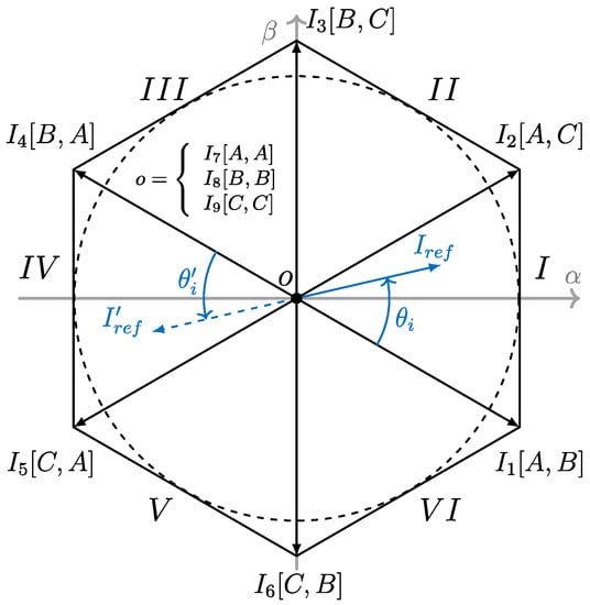
Figure 4.
Space vectors of the input current rectifier.
Here, dα and dβ are the duty cycles of the sector’s first and second vectors. The rest of the switching period is covered by one of the zero vectors, indicated by d0i. In addition, mc is the modulation index of the current source rectifier and is equal to
in which Iref is the amplitude of the desired input phase current and Idc is the current synthesized in the dc link. It is worth bearing in mind that, generally, there is no predefined value for Iref and the only important parameter is θi, which determines the power factor. Since the input CSR must supply Idc, which is assigned by the output load, Iref is set as equal to Idc leading to mc = 1. In this design, a phase-locked loop (PLL) measures the angle of the three-phase input line voltages. This algorithm applies the appropriate θi with reference to the angle of the input line voltages, considering the desired power factor.
For the output VSI, the space vectors are demonstrated in Figure 5, formed by six active vectors and two zero vectors. It should be noted that in this paper, the SVMPWM is implemented using line voltages, so the magnitudes of vectors are proportional to line values. The state of the converter on the output side of Figure 3a corresponds to the V1 in Figure 5.
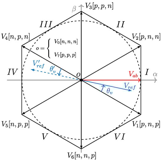
Figure 5.
Space vectors for the output voltage source inverter.
During one switching period, the reference voltage vector Vref is synthesized by two neighboring vectors and an appropriate combination of the zero vectors. Again, V’ref will be explained later in this section. For instance, in Figure 5, the reference vector is inside sector 1, then by switching V1 and V2, the reference voltage can be built. Depending on the magnitude of the reference vector, zero vectors may be required to cover the whole range of the switching period. The equations for the SVM modulation of the output converter are represented as follows:
where dγ and dδ are the duty cycle of the first and the second vectors in the sectors, respectively. Moreover, d0v represents the duty cycles of the zero vectors. Finally, mv is the modulation index of the VSI, which is defined as:
In contrast to the SVMPWM of the regular VSI with a fixed voltage in the DC link, the output voltage of the matrix converter directly correlates with the behavior of the input converter. Since CSR employs two different vectors during one switching period, two voltage levels will appear in the virtual DC link. Then, the switching pattern in Figure 6 is considered to fulfill the switching scheme in the input and the output. In this switching pattern, it is assumed that both reference vectors are in the first sector. Then:
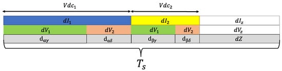
Figure 6.
Switching pattern during one period.
To simplify the representations, the following parameters are defined:
The authors in [46] proved that the averaged voltage in the virtual DC-link is constant and equal to
in which Vi is the amplitude of the input phase voltage and φi is the displacement angle of the input current regarding the input voltage. Taking all variations of the input and the output into account gives the following equations:
ROMAtrix uses transformers in its structure, which are subject to magnetic saturation. The flux balance technique guarantees correct performance of the matrix converter, without being affected by saturation [39]. That is, in the following switching period, the so-called T’s, both current and voltage reference vectors are rotated by as much as 180°. The vectors I’ref in Figure 4 and V’ref in Figure 5 represent the reversed reference vectors to realize the flux balance. Then, although different vectors are applied to the system, the power flow remains the same. If the flux balance technique is applied for the Ts (switching pattern in Figure 6), the result will be the T’S in Figure 7. As a result, the performance of the ROMAtrix has one extensive switching period, equal to Ts + T’s.
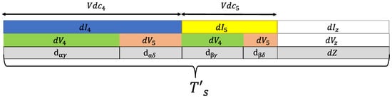
Figure 7.
Switching pattern during flux balance period, T’s.
4. Simulation
In this section, the performance of ROMAtrix was simulated using PLECS. The CSR side of the converter was connected to a 400VLL, 50 Hz three-phase source via an LC filter. The output VSI was directly connected to a 5Ω three-phase load. It was assumed that the medium frequency transformers were used in the design, so the switching frequency was set to 5 kHz. In addition, the turn ratio of the transformers was equal to 1. In these tests, creating a 200 V line voltage in the output was expected. At the beginning of the process, the algorithm received the reference voltage and current. As mentioned before, the amplitude of the reference current depends on the load, so only the angle of the input current was used to control the power factor on the grid side. Using the Clark transform, the reference vectors were transferred to the αβ-frame, as shown in Figure 4 and Figure 5. Then, the angles of vectors were adjusted to angles in the sectors, to calculate duty cycles using (8). In addition, the switching pattern was modified in this stage, to achieve soft switching on the CSR side. The new switching pattern is depicted in Figure 8. As shown, the current vectors were extended over the whole switching period, and zero vectors were distributed over the switching period of the VSI. In the new pattern, the duty cycles of CSR were modified as follows [47]:
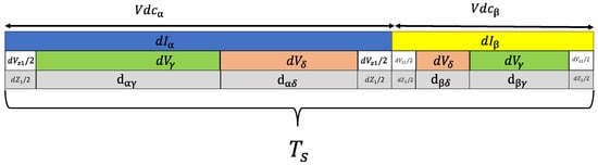
Figure 8.
Modified switching pattern.
This change in the length of the current vectors affected the voltage that appeared in the virtual DC-link:
in which Vα and Vβ are the voltages applied to the virtual DC-link when Iα and Iβ are active. To execute the flux balance technique, a parameter, namely S, was defined, which took 0 and 1, consecutively. When S = 0, the reference vectors were in their original sectors, while when S = 1, the reference vectors were transferred to the opposite sectors. This converter consisted of six input and output phases, each with six switch pairs. Then, taking into account the six sectors of the SVM plane and eight steps of the switching pattern, the control design required 1728 states in total. The unfiltered and filtered results of the simulation are shown in Figure 9 and Figure 10, respectively.
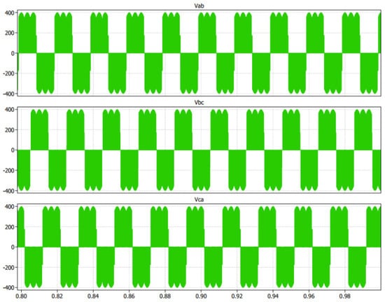
Figure 9.
Output line voltage of ROMAtrix, without filter from the simulation.
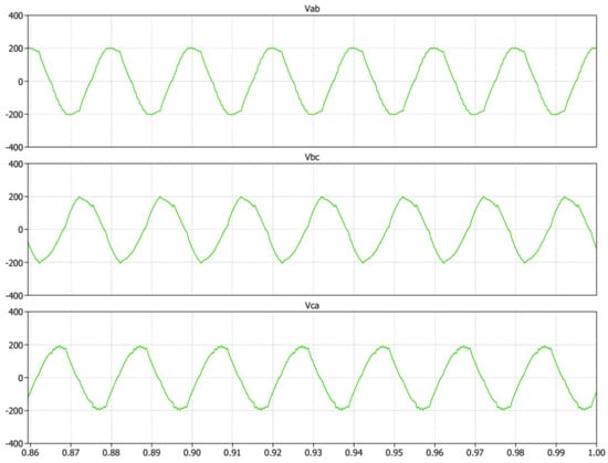
Figure 10.
Filtered output line voltage of ROMAtrix from the simulation.
An additional test was performed to verify the effect of unbalanced grid voltages on the output voltages and input currents. Although based on different standards, the unbalanced voltage should be less than 5% of the nominal peak value [48]; to verify the effectiveness of the proposed conversion system, an overstated unbalanced voltage was applied to the system. This means the input voltage amplitude of phase B was equal to 80% of phases A and C. The simulation results under such a situation are presented in Figure 11. As shown in the figure, the unbalanced voltage source directly affected the output voltages; similarly to other topologies, a specific control strategy was required to compensate for the effect of unbalanced voltage conditions.
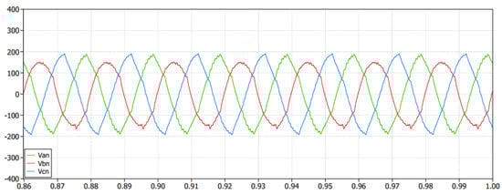
Figure 11.
Output line voltages under unbalanced grid voltages, simulation results.
5. FPGA Implementation and HIL Validation
In this section, performance of ROMAtrix was validated using HIL. The setup for the HIL implementation is shown in Figure 12, in which the PED-Board was an exclusively designed board for a wide variety of power electronic applications [49]. Using a National Instruments (NI) sbRIO-9651, the PED-board provides peripherals such as scalable PWM channels, fast analog to digital converters (ADC), various communication interfaces, and versatile I/Os, to name but a few. On the other hand, the HIL utilized the OPAL-RT eHS-64 solver, which was installed on the NI-PXIe 7868R module. The control of the ROMAtrix was implemented on PED-board, while ROMAtrix’s MATLAB model was loaded on the HIL. The PED-board took advantage of NI LabVIEW FPGA, as an interfacing software with users, which permitted avoiding the use of VHDL, while a maintaining high efficiency for the hardware resources used on the FPGA.
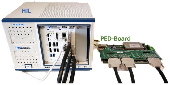
Figure 12.
Setup for the HIL implementation.
The voltage source and the load for the HIL implementation were the same as in the simulation. The HIL implementation results, with unfiltered and filtered shapes, are illustrated in Figure 13 and Figure 14, respectively. The maximum analog output of the PXIe 7868R is 10 V, so an appropriate scale should be applied, in order to read the voltage using an oscilloscope. Here, each unit of the oscilloscope represents 200 V. The measured voltages of the simulation and HIL were compatible with each other. Both implementations could achieve the desired values. The slight discrepancy between the two figures was due to the filters used in the HIL measurements. The output waveform contained low-frequency harmonics, which were due to the common-mode voltage. As a matter of fact, in the ROMAtrix, in each switching sector, different phases play the role of the positive and negative poles of the DC-link, which results in a significant common-mode voltage (CMV). It is the task of future works to eliminate these undesired phenomena from the output waveforms.
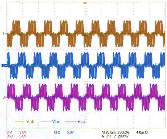
Figure 13.
Output line voltage of the ROMAtrix, without filtering, from HIL [scale 500 V/div].
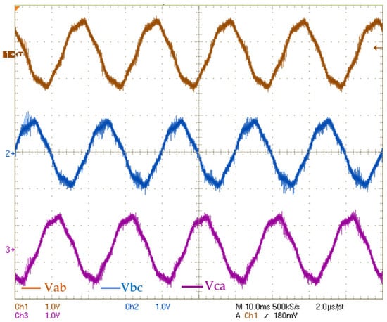
Figure 14.
Output line voltage of the ROMAtrix, from HIL (scale 200 V/div).
The effect of an unbalanced voltage was also tested in the HIL and is shown in Figure 15. Similarly, to the simulation case, the unbalanced input affected all three phases, while it affected phase C more than the two other phases.
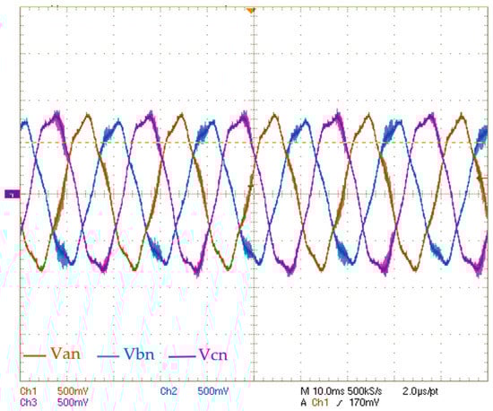
Figure 15.
Line voltages under unbalanced input grid voltages, the HIL results (scale 100 V/div).
6. Conclusions
This paper presented the implementation of an FPGA-based control board for space vector modulation pulse width modulation, using specific switching patterns for the ROMAtrix, a smart transformer. This ST has a special design, making it adaptable to medium voltage grids. As a matrix converter, ROMAtrix provides several advantages, such as a smaller footprint and lower cost. First, ROMAtrix and its working principle were reviewed. Then, the switching strategy used in this research work was described thoroughly. Finally, the simulation and the HIL implementation of the converter were presented in detail. The control of the ROMAtrix was designed with an exclusive power electronic board, the so-called PED-Board, and its HIL model was implemented in NI-PXIe 7868R. Different tests were presented. In the first, the converter operated in the normal situation of the grid, whilst, in the second test, the capability of the converter under a grid voltage unbalance was successfully evaluated. The results acquired from the simulation and the HIL validated each other. The unbalanced voltage source directly affected the output waveforms. Future works will pursue several objectives. First, the origin of the CMV in the output waveforms will be investigated, to improve the system performance. After the implementation of the proposed topology on a laboratory prototype, the inclusion of an additional port, which will enable connecting battery storage to the converter, will be investigated.
Author Contributions
Conceptualization, A.O. and S.B.; methodology, A.O. and S.B.; software, A.O.; validation, A.O. and S.B.; formal analysis, A.O. and S.B.; investigation, A.O. and S.B.; resources, A.O. and S.B.; data curation, A.O. and S.B.; writing—original draft preparation, A.O.; writing—review and editing, A.O. and S.B.; visualization, A.O.; supervision, S.B.; project administration, S.B.; funding acquisition, S.B. All authors have read and agreed to the published version of the manuscript.
Funding
This research was funded by the project: NoPoint—Active Power Nodes for the Internet of Energy—Efficient use of storage units in the telecommunications and electric mobility sectors, grant number A0375-2020-36774 Regione Lazio—POR FESR LAZIO 2014–2020—CUP:F85F21001560009.
Data Availability Statement
Not applicable.
Conflicts of Interest
The authors declare no conflict of interest.
References
- Saeed, M.H.; Fangzong, W.; Kalwar, B.A.; Iqbal, S. A Review on Microgrids’ Challenges Perspectives. IEEE Access 2021, 9, 166502–166517. [Google Scholar] [CrossRef]
- Davis, M.W. Distributed resource electric power systems offer significant advantages over central station generation and T & D power systems Part II. In Proceedings of the IEEE Power Engineering Society Transmission and Distribution Conference, Chicago, IL, USA, 21–25 July 2002; Volume 1, pp. 62–69. [Google Scholar] [CrossRef]
- Altaf, M.W.; Arif, M.T.; Islam, S.N.; Haque, E. Microgrid Protection Challenges and Mitigation Approaches–A Comprehensive Review. IEEE Access 2022, 10, 38895–38922. [Google Scholar] [CrossRef]
- Granata, S.; Di Benedetto, M.; Terlizzi, C.; Leuzzi, R.; Bifaretti, S.; Zanchetta, P. Power Electronics Converters for the Internet of Energy: A Review. Energies 2022, 15, 2604. [Google Scholar] [CrossRef]
- Bifaretti, S.; Bonaiuto, V.; Pipolo, S.; Terlizzi, C.; Zanchetta, P.; Gallinelli, F.; Alessandroni, S. Power Flow Management by Active Nodes: A Case Study in Real Operating Conditions. Energies 2021, 14, 4519. [Google Scholar] [CrossRef]
- Rodrigues, J.; Moreira, C.; Lopes, J.P. Smart Transformers as Active Interfaces Enabling the Provision of Power-Frequency Regulation Services from Distributed Resources in Hybrid AC/DC Grids. Appl. Sci. 2020, 10, 1434. [Google Scholar] [CrossRef]
- Mollik, M.S.; Hannan, M.A.; Reza, S.; Rahman, M.S.A.; Lipu, M.S.H.; Ker, P.J.; Mansor, M.; Muttaqi, K.M. The Advancement of Solid-State Transformer Technology and Its Operation and Control with Power Grids: A Review. Electronics 2022, 11, 2648. [Google Scholar] [CrossRef]
- Helali, H.; Khedher, A. Evaluation of different smart transformer structures under disturbed operating modes. Comput. Electr. Eng. 2022, 101, 108050. [Google Scholar] [CrossRef]
- Huber, J.E.; Kolar, J.W. Volume/weight/cost comparison of a 1MVA 10 kV/400 V solid-state against a conventional low-frequency distribution transformer. In Proceedings of the 2014 IEEE Energy Conversion Congress and Exposition (ECCE), Pittsburgh, PA, USA, 14–18 September 2014; pp. 4545–4552. [Google Scholar] [CrossRef]
- Alam, S.; Al-Ismail, F.S.; Salem, A.; Abido, M.A. High-Level Penetration of Renewable Energy Sources Into Grid Utility: Challenges and Solutions. IEEE Access 2020, 8, 190277–190299. [Google Scholar] [CrossRef]
- Burkard, J.; Biela, J. Design of a Protection Concept for a 100-kVA Hybrid Transformer. IEEE Trans. Power Electron. 2020, 35, 3543–3557. [Google Scholar] [CrossRef]
- GE Research and Prolec GE Power Up World’s 1st Large Flexible Transformer to Enhance the Resiliency of America’s Grid. Available online: https://www.ge.com/news/press-releases/ge-research-and-prolec-ge-power-up-worlds-1st-large-flexible-transformer-to-enhance (accessed on 18 October 2021).
- Martinez, C.N.A. Power Transformers Monitoring. J. Acoust. Emiss. 2019, 36, pn-o.2. [Google Scholar]
- Yilmaz, M.; Krein, P.T. Review of Battery Charger Topologies, Charging Power Levels, and Infrastructure for Plug-In Electric and Hybrid Vehicles. IEEE Trans. Power Electron. 2013, 28, 2151–2169. [Google Scholar] [CrossRef]
- She, X.; Huang, A.Q.; Burgos, R. Review of Solid-State Transformer Technologies and Their Application in Power Distribution Systems. IEEE J. Emerg. Sel. Top. Power Electron. 2013, 1, 186–198. [Google Scholar] [CrossRef]
- Huber, J.E.; Kolar, J.W. Applicability of Solid-State Transformers in Today’s and Future Distribution Grids. IEEE Trans. Smart Grid 2019, 10, 317–326. [Google Scholar] [CrossRef]
- AC-AC Converter with High Frequency Link. 2008. Available online: https://patentcenter.uspto.gov/applications/12173549 (accessed on 25 August 2022).
- Wrede, H.; Staudt, V.; Steimel, A. Design of an electronic power transformer. In Proceedings of the IECON Proceedings (Industrial Electronics Conference), Seville, Spain, 5–8 November 2002; Volume 2, pp. 1380–1385. [Google Scholar] [CrossRef]
- Lee, H.; Smet, V.; Tummala, R. A Review of SiC Power Module Packaging Technologies: Challenges, Advances, and Emerging Issues. IEEE J. Emerg. Sel. Top. Power Electron. 2020, 8, 239–255. [Google Scholar] [CrossRef]
- Loncarski, J.; Monopoli, V.G.; Leuzzi, R.; Ristic, L.; Cupertino, F. Analytical and Simulation Fair Comparison of Three Level Si IGBT Based NPC Topologies and Two Level SiC MOSFET Based Topology for High Speed Drives. Energies 2019, 12, 4571. [Google Scholar] [CrossRef]
- Ourahou, M.; Ayrir, W.; EL Hassouni, B.; Haddi, A. Review on smart grid control and reliability in presence of renewable energies: Challenges and prospects. Math. Comput. Simul. 2020, 167, 19–31. [Google Scholar] [CrossRef]
- Raghavan, B.; Ma, J. The energy and emergy of the internet. In Proceedings of the 10th ACM Workshop on Hot Topics in Networks—HotNets ’11, Cambridge, MA, USA, 14–15 November 2011; pp. 1–6. [Google Scholar] [CrossRef]
- Wang, K.; Yu, J.; Yu, Y.; Qian, Y.; Zeng, D.; Guo, S.; Xiang, Y.; Wu, J. A Survey on Energy Internet: Architecture, Approach, and Emerging Technologies. IEEE Syst. J. 2018, 12, 2403–2416. [Google Scholar] [CrossRef]
- Song, X. Research on Security Protection Architecture of Energy Internet Information Communication. MATEC Web Conf. 2018, 228, 02010. [Google Scholar] [CrossRef]
- Lin, C.-C.; Deng, D.-J.; Kuo, C.-C.; Liang, Y.-L. Optimal Charging Control of Energy Storage and Electric Vehicle of an Individual in the Internet of Energy With Energy Trading. IEEE Trans. Ind. Inform. 2018, 14, 2570–2578. [Google Scholar] [CrossRef]
- Zhou, Z.; Gong, J.; He, Y.; Zhang, Y. Software Defined Machine-to-Machine Communication for Smart Energy Management. IEEE Commun. Mag. 2017, 55, 52–60. [Google Scholar] [CrossRef]
- Pena-Alzola, R.; Gohil, G.; Mathe, L.; Liserre, M.; Blaabjerg, F. Review of modular power converters solutions for smart transformer in distribution system. In Proceedings of the 2013 IEEE Energy Conversion Congress and Exposition, ECCE 2013, Denver, CO, USA, 15–19 September 2013; pp. 380–387. [Google Scholar] [CrossRef]
- Rehman, A.; Imran-Daud, M.; Haider, S.K.; Rehman, A.U.; Shafiq, M.; Eldin, E.T. Comprehensive Review of Solid State Transformers in the Distribution System: From High Voltage Power Components to the Field Application. Symmetry 2022, 14, 2027. [Google Scholar] [CrossRef]
- She, X.; Burgos, R.; Wang, G.; Wang, F.; Huang, A.Q. Review of solid state transformer in the distribution system: From components to field application. In Proceedings of the 2012 IEEE Energy Conversion Congress and Exposition (ECCE), Raleigh, NC, USA, 15–20 September 2012; pp. 4077–4084. [Google Scholar] [CrossRef]
- Shadfar, H.; Pashakolaei, M.G.; Foroud, A.A. Solid-state transformers: An overview of the concept, topology, and its applications in the smart grid. Int. Trans. Electr. Energy Syst. 2021, 31, e12996. [Google Scholar] [CrossRef]
- Falcones, S.; Mao, X.; Ayyanar, R. Topology comparison for solid state transformer implementation. In Proceedings of the IEEE PES General Meeting, Minneapolis, MN, USA, 25–29 July 2010. [Google Scholar] [CrossRef]
- Casarin, J.; Ladoux, P.; Martin, J.; Chauchat, B. AC/DC converter with medium frequency link for railway traction application. Evaluation of semiconductor losses and operating limits. In Proceedings of the SPEEDAM 2010—International Symposium on Power Electronics, Electrical Drives, Automation and Motion, Pisa, Italy, 14–16 June 2010; pp. 1706–1711. [Google Scholar] [CrossRef]
- Marzoughi, A.; Burgos, R.; Boroyevich, D.; Xue, Y. Design and comparison of cascaded H-bridge, modular multilevel converter and 5-L active neutral point clamped topologies for drive application. In Proceedings of the 2015 IEEE Energy Conversion Congress and Exposition, ECCE 2015, Montreal, QC, Canada, 20–24 September 2015; pp. 4033–4039. [Google Scholar] [CrossRef]
- Ying, J.; Gan, H. High power conversion technologies & trend. In Proceedings of the Conference Proceedings—2012 IEEE 7th International Power Electronics and Motion Control Conference—ECCE Asia, IPEMC 2012, Harbin, China, 2–5 June 2012; Volume 3, pp. 1766–1770. [Google Scholar] [CrossRef]
- Bai, Z.; Xia, H.; Ma, H.; Wang, J. MMC capacitor voltage balancing strategy based on carrier rotation. In Proceedings of the Proceedings—2018 IEEE International Power Electronics and Application Conference and Exposition, PEAC 2018, Shenzhen, China, 4–7 November 2018. [Google Scholar] [CrossRef]
- Yin, T.; Wang, Y.; Wang, X.; Yin, S.; Sun, S.; Li, G. Modular Multilevel Converter with Capacitor Voltage Self-balancing Using Reduced Number of Voltage Sensors. In Proceedings of the 2018 International Power Electronics Conference, IPEC-Niigata—ECCE Asia 2018, Niigata, Japan, 20–24 May 2018; pp. 1455–1459. [Google Scholar] [CrossRef]
- Nasir, U.; Costabeber, A.; Wheeler, P.; Rivera, M.; Clare, J. A Three-Phase Modular Isolated Matrix Converter. IEEE Trans. Power Electron. 2019, 34, 11760–11773. [Google Scholar] [CrossRef]
- Liu, Y.; Liu, Y.; Ge, B.; Abu-Rub, H. Interactive Grid Interfacing System by Matrix-Converter-Based Solid State Transformer With Model Predictive Control. IEEE Trans. Ind. Inform. 2020, 16, 2533–2541. [Google Scholar] [CrossRef]
- Basu, K.; Shahani, A.; Sahoo, A.K.; Mohan, N. A Single-Stage Solid-State Transformer for PWM AC Drive With Source-Based Commutation of Leakage Energy. IEEE Trans. Power Electron. 2014, 30, 1734–1746. [Google Scholar] [CrossRef]
- Bravo, P.; Pereda, J.; Merlin, M.M.C.; Neira, S.; Green, T.C.; Rojas, F. Modular Multilevel Matrix Converter as Solid State Transformer for Medium and High Voltage AC Substations. IEEE Trans. Power Deliv. 2022, 37, 5033–5043. [Google Scholar] [CrossRef]
- Dao, N.D.; Nguyen, H.V.; Lee, D.-C. Semi-Modular Solid-State Transformers With Reduced Count of Components Based on Single-Stage AC/DC Converters. IEEE Trans. Power Electron. 2022, 37, 8177–8189. [Google Scholar] [CrossRef]
- Pipolo, S.; Bifaretti, S.; Lidozzi, A.; Solero, L.; Crescimbini, F.; Zanchetta, P. The ROMAtrix converter: Concept and operation. In Proceedings of the 2017 IEEE Southern Power Electronics Conference, SPEC 2017, Puerto Varas, Chile, 4–7 December 2017; Volume 2018, pp. 1–6. [Google Scholar] [CrossRef]
- Das, M.K.; Capell, C.; Grider, D.E.; Leslie, S.; Ostop, J.; Raju, R.; Schutten, M.; Nasadoski, J.; Hefner, A. 10 kV, 120 A SiC half H-bridge power MOSFET modules suitable for high frequency, medium voltage applications. In Proceedings of the 2011 IEEE Energy Conversion Congress and Exposition, Phoenix, AZ, USA, 17–22 September 2011; pp. 2689–2692. [Google Scholar] [CrossRef]
- Bifaretti, S.; Zanchetta, P.; Watson, A.; Tarisciotti, L.; Clare, J.C. Advanced Power Electronic Conversion and Control System for Universal and Flexible Power Management. IEEE Trans. Smart Grid 2011, 2, 231–243. [Google Scholar] [CrossRef]
- Bifaretti, S.; Zanchetta, P.; Fan, Y.; Iov, F.; Clare, J. Power flow control through a multi-level H-bridge based power converter for Universal and Flexible Power Management in future electrical grids. In Proceedings of the 2008 13th International Power Electronics and Motion Control Conference, Poznan, Poland, 1–3 September 2008; pp. 1771–1778. [Google Scholar] [CrossRef]
- Huber, L.; Borojevic, D. Space vector modulated three-phase to three-phase matrix converter with input power factor correction. IEEE Trans. Ind. Appl. 1995, 31, 1234–1246. [Google Scholar] [CrossRef]
- Wheeler, P.; Lie, X.; Meng, Y.L.; Empringham, L.; Klumpner, C.; Clare, J. A review of multi-level matrix converter topologies. In Proceedings of the IET Conference Publications, no. 538 CP, York, UK, 2–4 April 2008; pp. 286–290. [Google Scholar] [CrossRef]
- Girigoudar, K.; Molzahn, D.K.; Roald, L.A. On the relationships among different voltage unbalance definitions. In Proceedings of the 2019 North American Power Symposium (NAPS), Wichita, KS, USA, 13–15 October 2019; pp. 1–6. [Google Scholar] [CrossRef]
- PED-Board | Just Add Power. Available online: https://www.ped-board.com/ (accessed on 25 August 2022).


Disclaimer/Publisher’s Note: The statements, opinions and data contained in all publications are solely those of the individual author(s) and contributor(s) and not of MDPI and/or the editor(s). MDPI and/or the editor(s) disclaim responsibility for any injury to people or property resulting from any ideas, methods, instructions or products referred to in the content. |
© 2023 by the authors. Licensee MDPI, Basel, Switzerland. This article is an open access article distributed under the terms and conditions of the Creative Commons Attribution (CC BY) license (https://creativecommons.org/licenses/by/4.0/).