Article

Durability Effects of Gas Nozzle Shape on Marine Two-Stroke Dual-Fuel Engines Using Numerical Analysis

1
Korea Institute of Maritime and Fisheries Technology, 367, Haeyang-ro, Yeongdo-gu, Busan 49111, Republic of Korea
2
Division of Marine System Engineering, Korea Maritime and Ocean University, 727, Taejong-ro, Yeongdo-gu, Busan 49112, Republic of Korea
*
Author to whom correspondence should be addressed.
Machines 2023, 11(4), 456; https://doi.org/10.3390/machines11040456
Submission received: 3 March 2023 / Revised: 30 March 2023 / Accepted: 1 April 2023 / Published: 4 April 2023

Abstract

:
To comply with rules on air pollutants released by ships, two-stroke dual-fuel engines with liquefied natural gas (LNG) as the primary fuel have been marketed and offered to the market. However, there are still reports of gas-injection nozzles being damaged after they have been put on the market. Damage to the nozzles might result in secondary accidents in addition to worsening engine combustion conditions from improper injection. This study aims to gather fundamental information regarding the impact of different types of gas-injection nozzles on durability and to pinpoint the prerequisites for an ideal nozzle design. The results of total deformation and equivalent stress were examined for 27 nozzles that each variable was applied to in order to compare and confirm the durability by changing the nozzle shape. The cause of the nozzle temperature change according to the change in nozzle length was found to have the biggest impact on the total deformation, and it was confirmed that the effect was increased at higher temperatures. As the nozzle length increased and decreased by 2 mm, the average temperature of the nozzle increased by 47% and decreased by 53%, but the total deformation increased by 100% and decreased by 70%. It was verified that the equivalent stress was determined by the complicated interplay between the pressure inside the nozzle and turbulent kinetic energy impacted by a change in the nozzle shape. The factor that has the largest influence on the equivalent stress is the adjustment of the nozzle hole pipe angle, and the difference in equivalent stress according to this factor was found to be up to 118% and at least 44%. As a result, it has been proven that shortening the nozzle length, increasing the hole pipe angle, and enlarging the hole diameter are the most effective and expected to be used as basic data for future nozzle development.

1. Introduction

Existing ships equipped with diesel engines as propulsion generally use low-grade oil containing 10 or more hydrocarbons as the main fuel, which is the main source of exhaust pollutants during the combustion process [1]. To respond to this, in 2015, the world’s first dual-fuel (DF) diesel engine was launched, which uses a small percentage of existing marine fuel as pilot fuel and liquefied natural gas (LNG) as the main fuel [2].
LNG, whose main component is methane, is known to produce very low levels of air pollutants compared to conventional marine fuels [3]. It has the advantage of being able to use boil off gas (BOG), which is generated due to the nature of liquefied natural gas in LNG carriers, as a fuel for ship propulsion. Compared to other alternative fuels, it is a commercialized technology that is easy to produce, supply, and store, so industry needs have been sufficiently secured and developed as a priority [4].
In the high-pressure dual-fuel engine, a high-pressure spray of 300 bar is applied from the gas nozzle. In this context, cases have been reported where the nozzles have been damaged, as shown in Figure 1. Attempts were made to change the length and shape of the nozzle or to replace the nozzle material. However, damage still occurred after a certain period of operation. Nozzle breakage during operation not only worsens the combustion condition of the engine due to improper injection, but also can lead to secondary accidents. Exhaust emissions from incomplete combustion are harmful air pollutants that have a negative impact on the global eco-friendliness trend [5,6,7]. The durability of ship machinery is an important factor because it is difficult for ships to supply spares for repair rapidly while in operation.
Previous studies on nozzle injection have mainly focused on the combustion and emission exhaust characteristics as opposed to studies on nozzle durability [8,9,10].
Maghbouli et al. [11] reported that the nozzle position, which determines the injection position (IP), has a significant effect on both the in-cylinder pressure and exhaust gas emission (EGE) of the fuel direct-injection engine. Even if the axial position of the fuel nozzle was changed by only a few millimeters, the engine performance and exhaust behavior changed significantly. Mobasheri and Peng [12] concluded that narrow-angle injection contributed to a reduction in NOx and soot emissions due to the improved quality of the fuel–air mixture without affecting fuel oil consumption. Yoon et al. [13] investigated the effectiveness of injection angles (spray angle) and fuel-injection strategies on the combustion and emission characteristics of direct-injection engines fueled with dimethyl ether (DME). They found that peak in-cylinder pressure increased over a narrow angle injection (60° and 70°) more than a wide injection method (156°) in a single-injection strategy with an advanced fuel-injection timing system.
In a direct-injection compression-ignition diesel engine, the target injection point of the engine combustion chamber is very important because the combustion chamber wall is wet to form unburned hydrocarbons (UHC), and the O2 consumption during the combustion process varies greatly depending on the target point [14,15,16].
The rapid combustion of the fuel-rich region in the engine combustion chamber leads to a decrease in combustion efficiency, knocking, and high levels of NOx emissions from the engine. Therefore, several researchers have attempted to determine the optimal spray angle [17,18,19,20]. Fang et al. [20] reported that using narrow-angle injection with an injection angle of 70° resulted in more soot formation due to the deposition of a fuel film on the piston wall. However, NOx emissions are lowered due to the lean fuel–air mixture near the piston surface. Shu et al. [2] used a computational fluid dynamic (CFD) analysis method combined with a chemical kinetic model to investigate the emission characteristics of a DF engine at different injection angles. They concluded that NOx emissions increased by 93% when the fuel-injection angle was increased from 60° to 140°, but decreased by 15% when the injection angle was further increased to 160°. Lim and Min [21] performed a computational fluid dynamic analysis of a diesel engine operated at different injection angles to reduce soot and minimize impact on the walls. It was found that soot was reduced by 41% at a 100° spray angle compared to a 70° spray angle. Di Iorio et al. [22] used the CI engine to measure combustion performance and analyze exhaust gas emissions at various speeds and loads by dividing them into diesel mode and DF mode. They found that the DF operation resulted in a longer combustion period and lower peak pressure compared to conventional diesel fuels due to the lower flame propagation of methane. Additionally, optical investigations demonstrated that DF combustion results in lower cylinder soot formation and lower temperatures than diesel operation, resulting in lower particulate and NOx emissions. As shown in the literature review above, studies on ship dual-fuel engine nozzles have mainly focused on exhaust emissions based on nozzle shape, and durability studies are very limited.
Therefore, 27 nozzle cases were modeled in this study using nozzle length, the diameter of the hole pipe, and the hole pipe angle, based on a nozzle installed in the DF engine currently on the market. The pressure generated at the inner wall of the nozzle during fuel spraying was extracted by an injection simulation. In addition, a thermal structure analysis was performed by applying this pressure along with the temperature affected by the nozzle. From the results of study, the conditions for increasing the durability of the nozzle in a harsh combustion environment were identified. It is expected that this can be used as base data to consider durability and efficiency in developing appropriate nozzles of the optimized engine structure and operating characteristics.
This study consists of the following. In second chapter, the geometry and material properties of the modified nozzle based on the commercial nozzle are described. It contains the primary model configuration, interface, initial settings, and validation results for each simulation. The third chapter analyzes and discusses the pressure, total deformation amount, and equivalent stress changes inside the nozzle according to variable conditions, and the fourth chapter summarizes the analysis results and provides future research prospects.

2. Materials and Boundary Condition

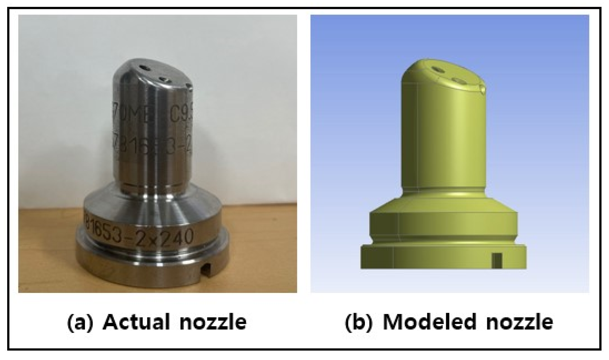
2.1. Nozzle Modeling

This study was conducted with a gas-injection nozzle equipped with a commercial high-pressure diesel cycle dual-fuel engine. An image of the actual nozzle is shown in Figure 2a and the image converted to a three-dimensional model in Figure 2b. The design of the nozzle refers to the 2D drawing and was implemented as a 3D model using Rhino software, a 3D design program. Based on the existing model, (a) nozzle length, (b) nozzle hole pipe diameter, and (c) nozzle hole pipe angle were changed, and 27 nozzles, including the existing model, were simulated.
The nozzle used in this study had five injection holes. The position and injection angle of each hole are not uniform, as listed in Table 1. To minimize the influence of external factors, the hole position and shape of the nozzle are fixed.
The diameter of the nozzle hole pipe was adjusted at a rate of ±10% because the diameter of the pipe connected to the five holes was not uniform. The nozzle hole pipe angle was ±10° only for the Z-axis angle, while the X- and Y-axis directions were fixed. The nozzle length was prevented from affecting the other variable conditions by adjusting the length of the top of the nozzle hole pipe.

2.2. Nozzle Materials

The material that the nozzle is made of is an important factor that affects its durability. The commercially available nozzle material was made of SKD61 (JIS G4404 Standard), and Table 2 lists the main chemical ratios of SKD61 [23]. The main properties of SKD61 are its excellent tensile strength at high temperatures due to its high molybdenum content, good heat resistance due to toughness caused by vanadium, and its high resistance to cracking and deformation caused by heat. Table 3 lists the main properties of SKD61 [24,25].

2.3. Spray Simulation

For spray simulation, commercial flow analysis program ‘Ansys 19.2b ver. Fluent’ verified through various studies was used [26,27].

2.3.1. Boundary Conditions and Initial Conditions

As shown in Figure 3, the model for spray analysis consisted of a nozzle placed in the center of a 60 mm cylinder with an open top and bottom. Liquid diesel was supplied constantly at an initial pressure of 300 bar at the nozzle inlet. The pressure outlet condition was set to 0 bar, which is the atmospheric pressure, so that the injected fuel and air were mixed at the upper and lower interfaces of the open cylinder at atmospheric pressure, and the fluid flow continued at atmospheric pressure.
It is well-known that the results of finite element analysis are affected not only by the initial input and boundary conditions but also by the quality of the lattice consisting of nodes and elements. A relatively dense grid was built inside and around the nozzle where fluid flow is expected to change, and this study intensively analyzed it. The simulation model consisted of the main configuration conditions, as shown in Table 4.

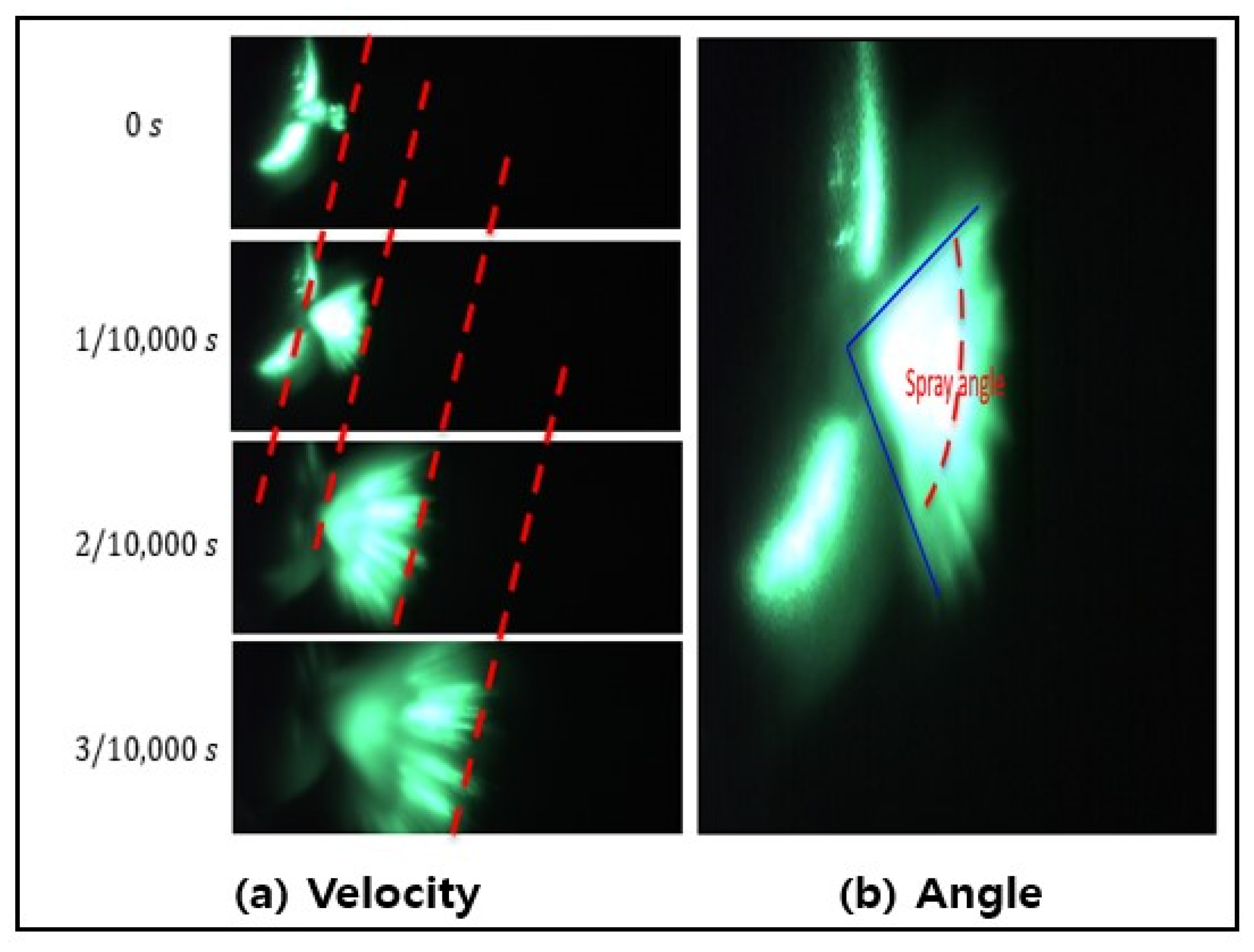
2.3.2. Model Validation

To compare and verify the spray analysis model in this study, an experiment was conducted, and the experimental and simulated results were compared for the spray angle and spray velocity. Figure 4 shows a schematic diagram of the experimental setup used to verify the fluid analysis calculation model. A fuel-injection valve equipped with an injection nozzle was installed on the test table. After pressure was built up with a hydraulic power unit, fuel was sprayed into the cylinder according to the injection signal. To obtain a spray image, a 532 nm, 2.5 W diode laser was irradiated onto a cylindrical lens to create a plane wave in the spray area of the nozzle. Images were captured at a speed of 10,000 fps using a high-speed camera, and the captured images were analyzed. To obtain a clear spray image, the effect of the residual gas in the cylinder was minimized by running the experiment at specific time intervals after each spray.
In the analysis, the distance per pixel through the image and the actual diameter of the nozzle hole were determined, and the spray velocity was calculated using the length of the tip of the sprayed fluid extended from the nozzle tip and the acquisition time, as shown in Figure 5a. As shown in Figure 5b, the nozzle angle was defined as the angle between the two outermost points of the spray, based on the fluid sprayed from one hole, and the spray angle was calculated. MATLAB software was used to convert the three primary colors (RGB) per pixel of the image into grayscale and they were quantified. The accuracy and objectivity of the analysis were improved by selecting the spray tip for the spray speed and the two outermost points for the spray angle as quantitative values.
Figure 6 shows the results of the comparison between the simulation and experiment at the four injection pressures. The maximum deviation occurred within 2% of the spraying speed and 4% of the spraying angle. These deviations are within the 10% limit, which is acceptable for the reliability of the computational fluid analysis model, and it shows that the numerical simulation results and the experimental results agree well [30,31].

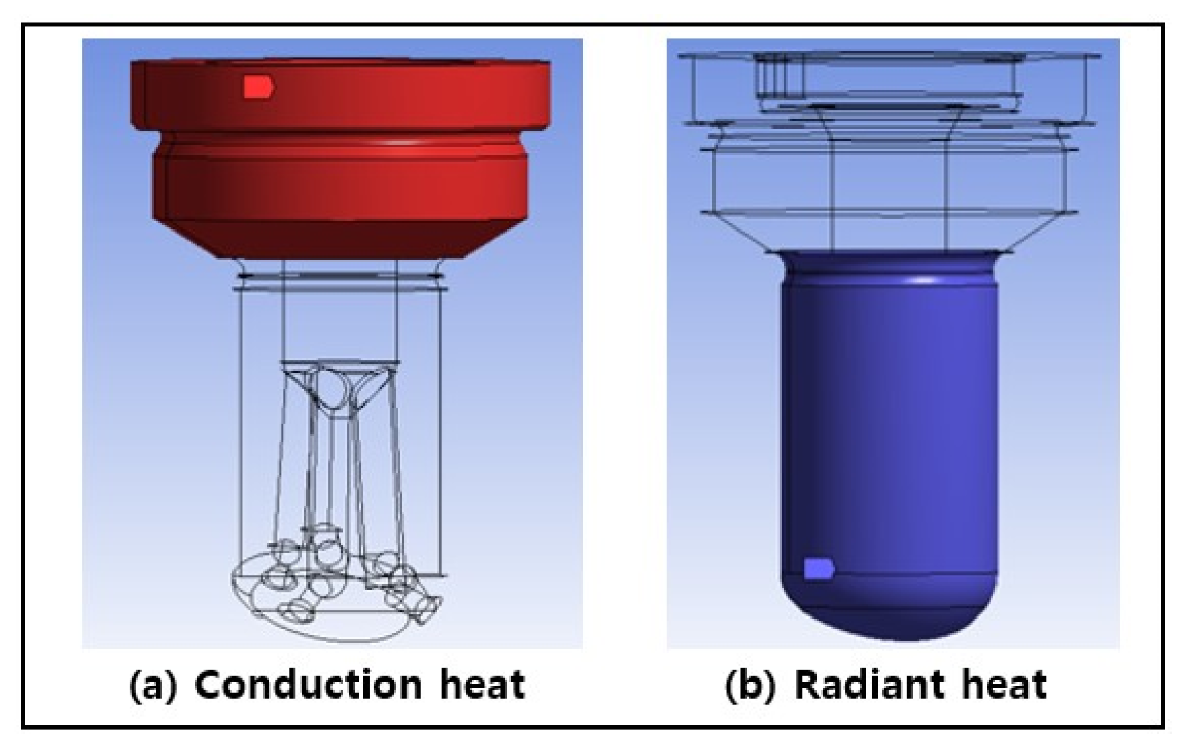
2.4. Thermal-Structure Simulation

For structure simulation, commercial structural analysis program ‘Ansys 19.2b ver. Mechanical’ verified through various studies was used [32,33,34,35]. Material, heat treatment method, shape, boundary condition, direction of force, etc., are important factors affecting the results of structural analysis. The nozzle material and heat treatment method irrelevant to the variable conditions in this study were applied in the same way by referring to the results of other studies on the material used in the nozzle. The focus was on identifying the trends according to the variables through the pressure and temperature conditions, which are the main key variables inside the actual engine.

Boundary Conditions and Initial Conditions

The nozzle located in the combustion chamber is subjected to numerous factors, such as, during engine operation, high pressure, radiant heat from the explosion, conduction heat, cooling water temperature, and fatigue conditions from repeated operation [3,36,37].
In this study, among the complex factors affecting the nozzle, the boundary conditions were limited to a total of three conditions: the nozzle internal pressure due to fuel supply, the radiant heat generated in the combustion chamber, and conduction heat transferred by the cooling water.
The red area in Figure 7a is the interface where the nozzle is in close contact with the valve body and the engine cylinder head. As the cooling water supplied to the cylinder head during engine operation affects the nozzles via conductive heat transfer phenomena, a typical cooling water temperature of 85 °C was set as the initial value. This boundary surface was designated as a constraint. The blue area in Figure 7b is the boundary where the nozzle is exposed in the combustion chamber is exposed and the heat generated by combustion is radiated and transferred. At this point, the radiant heat was designated as 1800 °C considering the average temperature in the cylinder as 1200 °C and the combustion temperature of methane–air as 2000 °C, and the emissivity of SKD61, 0.6, was entered.
Spray simulations were performed for the pressure conditions generated at the inner wall of the nozzle, and the results were applied. In Figure 8a–c, the pressure setting section was divided into three sections, and the pressure in each section was adjusted to uniformly reach the specified boundary surface.

2.5. Mesh Generation

The nozzle hole inlet surface where the damage phenomenon occurred, and the lattice inside the hole where the gas pressure acted, were densely constructed. Table 5 lists the average, maximum, and minimum values of the main factors representing the quality of the grid. The quality of the grating affects the results. In this study, the difference between the cases was minimized, and it was confirmed that the grid generation process did not affect the analysis by confirming that the main elements were within the standard value.

3. Results and Discussion

In this study, the total deformation and equivalent stresses were analyzed by spray analysis and thermal structure analysis for a commercial gas-injection nozzle (original model, case 1) and 26 nozzles modified according to variable conditions.

3.1. Pressure in the Inner Wall of the Nozzle

Figure 9 shows the results of the relative comparison of the average pressure generated at the inner wall of the lower part of the nozzle with respect to the existing nozzle and the nozzles to which the variables are applied, among the results of the spray analysis.
The pressure generated at the inner wall in the lower part of the nozzle increased from 110% to 150% as the nozzle hole pipe angle was adjusted by 10%, 0%, and −10% under the condition that the nozzle length and hole pipe diameter were the same.
In the initial situation, where a constant pressure is maintained, a decrease in the angle of the pipe suppresses the discharge flow, so that the pressure inside the nozzle pipe increases. It was also confirmed that, when the nozzle diameter was narrowed, a higher pressure was formed because the same pressure was concentrated on the narrow inner diameter. The adjustment to the hole pipe angle was identified as the largest factor in the pressure change.
Appendix A shows the results of the pressure generated at the inner wall of the nozzle. The pressure applied to the upper and central parts of the nozzle did not show a large difference within 3%, and the pressure on the lower side showed a large difference of ±80%. To increase the reliability of the structural analysis, this was applied to the structural analysis.

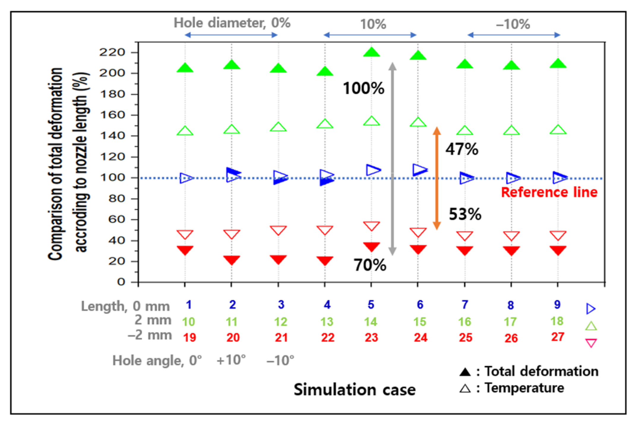
3.2. Total Deformation

The total deformation is the value of deformation with respect to the deformation from the original shape when a force is applied to the structure, as the sum of the amounts of deformation occurring in three dimensions. The analysis of total deformation in structural analysis helps in determining the maximum stress and strain levels that a structure can withstand before failure occurs [38,39].
Figure 10 shows the results of the comparative analysis of temperature and total deformation for the existing nozzle and the nozzle adjusted under variable conditions.
The nozzle length is the same as the existing nozzle, and nozzles (cases 2 to 9, symbol ▷) whose nozzle hole piping diameter and angle are adjusted show little change in nozzle temperature and total deformation compared with the original nozzle. Analysis of nozzles (cases 10 to 18, symbol △) which are 2 mm longer than the existing nozzles shows that the nozzle temperature increased by an average of 47% and the total deformation by an average of 100% compared with the existing nozzle. In the case of nozzles (cases 19–27, symbol ▽) with a 2 mm reduction in nozzle length, it was confirmed that the nozzle temperature decreased by an average of 53% and the total deformation by an average of 70%.
Consequently, it was confirmed that the total deformation was influenced by the nozzle length, whereas the diameter and angle of the nozzle hole pipe were not influencing factors.
An additional structural analysis was performed for the existing nozzle to clearly confirm the main causes of the influence of temperature and pressure on the total deformation. In cases 1 to 3, the pressure generated inside the nozzle was set to 30 MPa, 40 MPa, and 50 MPa, respectively, while the initial temperature was fixed, and in case 4, the temperature condition was excluded from the same 30 MPa pressure condition.
As shown in Figure 11a, the total deformation of the nozzle without the result of the thermal analysis was reduced by 98% when comparing the structural analysis with the case where the result of the thermal analysis was not considered. Figure 11b shows the change in total deformation when the pressure generated in the nozzle was increased from 30 MPa to 50 MPa while maintaining the same thermal analysis results. It can be seen that the difference is not large, depending on the change in pressure generated inside the nozzle. Thus, it was confirmed that the total deformation amount was affected by the temperature change of the nozzle compared to the effect of the pressure inside the nozzle.
To study the effect of temperature change on the total deformation amount in detail, the radiant heat temperature acting on the nozzle at constant internal pressure was changed at 200 °C intervals. As shown in Figure 11c, it was confirmed that the amount of deformation increased as the temperature of the radiant heat on the nozzle increased, with the range of increase also increasing at high temperatures.
This can be explained by the previous studies of M.X. Wei [40]. The change in hardness as a function of the heat treatment temperature change was checked for the H13 (designation SKD61 based on ASTM A681) material. They confirmed that the hardness of the material decreased with increasing material temperature. Hardness is a measure of resistance to surface wear. As hardness increased, toughness decreased, and there was a risk of breakage due to external influences.
The gas-injection nozzle in this study was attached to the combustion chamber, which had the highest temperature of all the engine configurations. One of the variables, nozzle length, affects the range exposed in the combustion chamber, resulting in a temperature change in the nozzle. As the nozzle range in the combustion chamber increases, the hardness decreases, leading to an increase in deformation. This can explain the result of this study that the rate of temperature change is similar depending on the nozzle length adjustment, but the extent of deformation is greater at high temperatures.
As a result, it was confirmed that the nozzle temperature change due to the nozzle length was the main cause of the total deformation, and the influence of the change in nozzle internal pressure due to the adjustment of the angle and diameter of the nozzle hole pipe was insignificant.

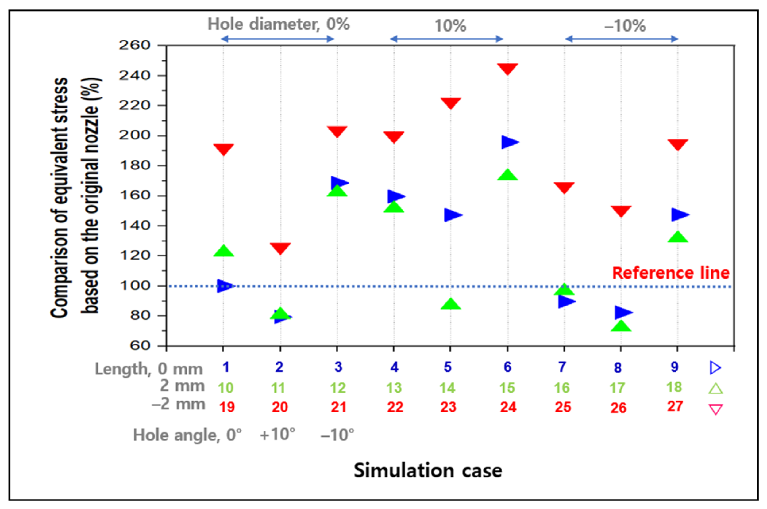
3.3. Equivalent Stress

Equivalent stress is particularly important in fatigue analysis, where it is used to evaluate the potential for repeated loading to cause cracks and eventual failure in a structure. It is expressed as the uniaxial tensile stress in a three-dimensional stress state based on one point. The principal stress has magnitude and direction as vectors, but the equivalent stress has only magnitude as a scalar. In a complex 3D model, it is difficult to determine the degree of deformation or damage based on the principal stress; therefore, it is judged only by the magnitude through the equivalent stress [23,34].
If the maximum value of equivalent stress is greater than the yield strength (tensile or compressive yield strength) of the material, that is, if the safety factor is less than 1, deformation may occur, and if it is greater than 1, it may be judged safe for the load condition [41,42,43]. The safety factor of the nozzle used in this study was less than 1, and no failure occurred under the load conditions considered in this study. However, this is the result of a single load. Depending on the fatigue properties of the material, which are described by the S–N curve, known as the fatigue limit curve, repeated loading can cause the material to fail, even if the yield strength is not reached during one load. It is well-known that fatigue failure spreads rapidly to the surrounding area when a small balance is formed at the point where stress is concentrated. If erosion from chemical reactions is then added, corrosion fatigue destruction can be accelerated.
Considering the characteristics of the nozzle in this study, which was repeatedly exposed to sadistic conditions for a short period of time, lowering the equivalent stress and identifying the location where the equivalent stress is concentrated are important factors in the durability of the nozzle.
Figure 5, Figure 6, Figure 7, Figure 8, Figure 9, Figure 10, Figure 11 and Figure 12 show the relative equivalent stress comparison ratio of the nozzles (cases 2–27) to which the variables are applied based on the existing nozzle (case 1). The equivalent stress increased when the nozzle hole pipe angle adjusted by −10% when the nozzle length and hole pipe diameter were the same. When the nozzle hole pipe diameter is adjusted by 10%, 0%, and −10%, the difference between the greatest (hole pipe angle −10%) and minimum (hole pipe angle +10%) values of the equivalent stress was compared. The nozzles with unchanged length were 87%, 88%, and 66%, while those with +2 mm adjustment were 81%, 86%, and 60%, and those with −2 mm adjustment were 78%, 118%, and 44%.
The equivalent stress is inversely proportional to the variable of the hole pipe angle. The average difference between the maximum and minimum values of equivalent stress for each nozzle whose pipe diameter was adjusted was 97%, 82%, and 57% in the order of +10%, 0%, and −10%, respectively. It can be seen that the smaller the nozzle hole pipe diameter, the smaller the effect of the nozzle angle on the stress.
To check the effect of nozzle length on stress, we compared the difference between the maximum and minimum stress values of depending on the angle for the same nozzle length, the nozzles adjusted −2 mm was 74%, whereas +2 mm of the nozzles adjusted +2 mm was 26%, and a difference greater than two times was confirmed.
It can be observed that the nozzle hole pipe angle is the main factor affecting the equivalent stress, and the smaller the nozzle diameter, the smaller the effect of the change of the nozzle angle on the equivalent stress. It can also be observed that the difference in the effect of nozzle angle and nozzle diameter increases as the nozzle becomes shorter.
As shown in Figure 9, it was found that the pressure generated at the inner wall of the lower part of the nozzle increased with the reduction in the nozzle hole pipe angle to 10%, 0%, and −10% under the conditions of the same nozzle length and hole pipe diameter as the equivalent stress. The equivalent stress was widely distributed according to the other variable conditions, but the pressure generated at the inner wall of the lower part of the nozzle was relatively uniform. The simulation results indicate that, by adjusting the nozzle shape, the equivalent stress is affected by the pressure generated at the inner wall of the nozzle, and the nozzle shape affects the pressure generated on the inner wall of the nozzle. The equivalent stress and pressure generated at the inner wall of the nozzle showed similar trends. However, compared to the pressure generated at the inner wall of the nozzle, the equivalent stress was not linearly proportional.
To confirm the effect of the pressure change at the inner wall of the nozzle on the equivalent stress, a separate simulation was performed with the pressure generated at the inner wall of the nozzle as a variable; the results are shown in Figure 13. It was found that the equivalent stress is linearly proportional to the rate at which the pressure generated at the inner wall of the nozzle increases. This is because the angle of the nozzle hole pipe has the greatest effect on the pressure generated at the inner wall of the nozzle, and the diameter and length of the nozzle hole pipe affect the pressure generated on the inner wall of the nozzle. In addition to the applied pressure, other factors occur, and it is found that the equivalent stress is affected by these factors.
The visualized image of the turbulent kinetic energy distribution generated by the fluid flow at the nozzle under the results of the spray analysis and it is confirmed that the distribution is similar to the result of the equivalent stress analysis. To confirm the effect of turbulent kinetic energy on the equivalent stress, the effect of turbulent kinetic energy of the nozzle shape change was compared with that of the existing nozzle (case 1), as shown in Figure 14.
The variation in turbulent kinetic energy is comparable to the trend of equivalent stress in that the resultant value tends to increase as the nozzle hole pipe angle decreases, and the change range of the result decreases as the nozzle hole pipe diameter decreases. However, as the nozzle length decreased, the range of change in the generation rate of turbulent kinetic energy decreased, showing an opposite tendency to that of equivalent stress.
The turbulence generated in the nozzle occurs vortices, and the vibrational stress led to fatigue failure [44]. In other words, the turbulent kinetic energy is a factor that negatively affects the durability inside the nozzle and is considered as a secondary factor for the variation of equivalent stress in this study, along with the internal pressure.
The fact that the change of nozzle hole angle, the most significant aspect of this result, has the greatest effect on equivalent stress is consistent with previous studies indicating that erosion–corrosion is the primary cause of failure in the vicinity of bending in pipes through which high-pressure fluids flow [45,46].

4. Conclusions

In this study, thermal and structural analysis were performed on gas nozzles under conditions similar to that of the engine combustion chamber in order to identify the factors affecting nozzle durability in dual-fuel engines.
The main source of the effect of nozzle shape on the total deformation is the change in nozzle temperature according to the length of the nozzle; the angle and diameter of hole pipe adjustment effects of the nozzle hole pipe were found to be minimal. As the nozzle length increased and decreased by 2 mm, the average temperature of the nozzle increased by 47% and decreased by 53%, while the total deformation increased by 100% and decreased by 70%. The longer the nozzle length, the more exposed the engine combustion chamber, and the greater the nozzle temperature, which is detrimental to durability. The results demonstrate that the previous upgrade of reducing the length of commercial nozzles contributed to their greater longevity.
Equivalent stress increases as the angle of the nozzle hole pipe decreases, and the variation tends to diminish as the diameter of the nozzle hole pipe decreases. The nozzle shape adjustment affects the pressure generated on the inner wall of the nozzle and is similar to the change in equivalent stress. However, the pressure change caused by the nozzle’s inner wall is linear, whereas the equivalent stress is not. Similar to the tendency of equivalent stress, turbulent kinetic energy increases as the angle of the nozzle hole pipe drops and variation width reduces as the diameter of the nozzle hole pipe decreases. This confirms that the equivalent stress is determined by the complex interaction of turbulent kinetic energy and the pressure inside the nozzle influenced by changes in nozzle shape.
As a result of the study, shortening the nozzle length, increasing the hole pipe angle, and expanding the hole diameter were the most effective in order to improve the gas nozzle durability of the DF engine. The structure of the nozzle has a significant impact on combustion efficiency and exhaust emissions. In the future, research will be performed to determine the effect of nozzles with enhanced durability on engine combustion efficiency and exhaust emissions.

Author Contributions

Conceptualization, J.-S.K.; methodology, J.-S.K.; software, J.-S.K.; validation, J.-H.C.; formal analysis, J.-S.K.; data curation, J.-S.K.; writing—original draft preparation, J.-S.K.; writing—review and editing, J.-H.C.; supervision, J.-H.C. All authors have read and agreed to the published version of the manuscript.

Funding

This research was supported by Korea Institute of Marine Science & Technology Promotion (KIMST) funded by the Ministry of Oceans and Fisheries (20220630).

Data Availability Statement

Not applicable.

Conflicts of Interest

The authors declared no potential conflict of interest with respect to the research, authorship, and/or publication of this article.

Abbreviations

BOGboil-off gas
CFDcomputational fluid dynamics
DFdual fuel
DMEdimethyl ether
EGEexhaust gas emission
IPinjection position
LNGliquefied natural gas
UHCunburned hydrocarbons

Appendix A

Table A1. Average Pressure Value of Nozzle Inside for Structure Analysis.
Case(a) Upper Part of Nozzle Inside (MPa) (b) Middle Part of Nozzle Inside (MPa) (c) Lower Part of Nozzle Inside (MPa)
13.055-2.742-1.102-
23.040100%2.734100%0.54049%
33.03799%2.812103%1.682153%
43.044100%2.763101%1.356123%
53.081101%2.70299%0.36233%
63.044100%2.826103%1.658151%
73.03199%2.761101%1.362124%
83.03099%2.742100%0.52548%
93.02899%2.788102%2.099191%
103.02599%2.749100%1.447131%
113.03299%2.72699%0.45842%
123.02199%2.841104%1.707155%
133.042100%2.874105%1.521138%
143.048100%2.69498%0.43740%
153.02599%2.823103%1.706155%
163.02899%2.762101%1.204109%
173.02299%2.737100%0.53448%
183.01999%2.823103%1.977179%
193.063100%2.759101%1.230112%
203.061100%2.733100%0.30027%
213.046100%2.836103%1.710155%
223.072101%2.756100%1.294117%
233.068100%2.70299%0.35332%
243.044100%2.827103%1.697154%
253.03999%2.774101%1.169106%
263.046100%2.734100%0.36833%
273.03799%2.830103%2.006182%

References

  1. Bilgili, L. Life cycle comparison of marine fuels for IMO 2020 Sulphur Cap. Sci. Total Environ. 2021, 774, 145719. [Google Scholar] [CrossRef]
  2. Shu, J.; Fu, J.; Liu, J.; Ma, Y.; Wang, S.; Deng, B.; Zeng, D. Effects of injector spray angle on combustion and emissions characteristics of a natural gas (NG)-diesel dual fuel engine based on CFD coupled with reduced chemical kinetic model. Appl. Energy 2019, 233, 182–195. [Google Scholar] [CrossRef]
  3. Deng, J.; Wang, X.; Wei, Z.; Wang, L.; Wang, C.; Chen, Z. A review of NOx and SOx emission reduction technologies for marine diesel engines and the potential evaluation of liquefied natural gas fuelled vessels. Sci Total Environ. 2021, 766, 144319. [Google Scholar] [CrossRef]
  4. Sharafian, A.; Blomerus, P.; Mérida, W. Natural gas as a ship fuel: Assessment of greenhouse gas and air pollutant reduction potential. Energy Policy 2019, 131, 332–346. [Google Scholar] [CrossRef]
  5. Yusuf, A.A.; Inambao, F.L.; Ampah, J.D. Evaluation of biodiesel on speciated PM2.5, organic compound, ultrafine particle and gaseous emissions from a low-speed EPA Tier II marine diesel engine coupled with DPF, DEP and SCR filter at various loads. Energy 2022, 239, 121837. [Google Scholar] [CrossRef]
  6. Yusuf, A.A.; Yusuf, D.A.; Jie, Z.; Bello, T.Y.; Tambaya, M.; Abdullahi, B.; Muhammed-Dabo, I.A.; Yahuza, I.; Dandakouta, H. Influence of waste oil-biodiesel on toxic pollutants from marine engine coupled with emission reduction measures at various loads. Atmos. Pollut. Res. 2022, 13, 101258. [Google Scholar] [CrossRef]
  7. Chu Van, T.; Ramirez, J.; Rainey, T.; Ristovski, Z.; Brown, R.J. Global impacts of recent IMO regulations on marine fuel oil refining processes and ship emissions. Transp. Res. Part D Transp. Environ. 2019, 70, 123–134. [Google Scholar] [CrossRef]
  8. Andreadis, P.; Zobanakis, A.; Chryssakis, C.; Kaiktsis, L. Effects of the Fuel Injection Parameters on the Performance and Emissions Formation in a Large-Bore Marine Diesel Engine. Int. J. Engine Res. 2010, 12, 14–29. [Google Scholar] [CrossRef]
  9. Hayashi, T.; Suzuki, M.; Ikemoto, M. Effects of internal flow in a diesel nozzle on spray combustion. Int. J. Engine Res. 2013, 14, 646–654. [Google Scholar] [CrossRef]
  10. Korkmaz, M.; Ritter, D.; Jochim, B.; Beeckmann, J.; Abel, D.; Pitsch, H. Effects of injection strategy on performance and emissions metrics in a diesel/methane dual-fuel single-cylinder compression ignition engine. Int. J. Engine Res. 2019, 20, 1059–1072. [Google Scholar] [CrossRef]
  11. Maghbouli, A.; Yang, W.; An, H.; Li, J.; Shafee, S. Effects of Injection Strategies and Fuel Injector Configuration on Combustion and Emission Characteristics of a D.I. Diesel Engine Fueled by Bio-Diesel. Renew. Energy 2015, 76, 687–698. [Google Scholar] [CrossRef]
  12. Mobasheri, R.; Peng, Z. A Computational Investigation into the Effects of Included Spray Angle on Heavy-Duty Diesel Engine Operating Parameters. In Proceedings of the SAE 2012 International Powertrains, Fuels & Lubricants Meeting, Malmo, Sweden, 18–20 September 2012; SAE International: Warrendale, PA, USA, 2012. [Google Scholar]
  13. Yoon, S.H.; Cha, J.P.; Lee, C.S. An investigation of the effects of spray angle and injection strategy on dimethyl ether (DME) combustion and exhaust emission characteristics in a common-rail diesel engine. Fuel Process. Technol. 2010, 91, 1364–1372. [Google Scholar] [CrossRef]
  14. Park, S.W.; Reitz, R.D. Optimization of fuel/air mixture formation for stoichiometric diesel combustion using a 2-spray-angle group-hole nozzle. Fuel 2009, 88, 843–852. [Google Scholar] [CrossRef]
  15. Dolak, J.; Reitz, R.D. Optimization of the piston geometry of a diesel engine using a two-spray-angle nozzle. Proc. Inst. Mech. Eng. Part D J. Automob. Eng. 2011, 225, 406–421. [Google Scholar] [CrossRef]
  16. Taghavifar, H.; Mardani, A.; Mohebbi, A. Exhaust emissions prognostication for DI diesel group-hole injectors using a supervised artificial neural network approach. Fuel 2014, 125, 81–89. [Google Scholar] [CrossRef]
  17. Siewert, R.M. Spray Angle and Rail Pressure Study for Low NOx Diesel Combustion. In Proceedings of the SAE World Congress & Exhibition 2007, Detroit, MI, USA, 16–19 April 2007; SAE International: Warrendale, PA, USA, 2007. [Google Scholar]
  18. Kitasei, T.; Yamada, J.; Shoji, T.; Shiino, S.; Mori, K. Influence of the Different Fuel Spray Wall Impingement Angles on Smoke Emission in a DI-Diesel Engine; SAE International: Warrendale, PA, USA, 2008. [Google Scholar]
  19. Kim, H.; Reitz, R.; Kong, S.-C. Modeling Combustion and Emissions of HSDI Diesel Engines Using Injectors with Different Included Spray Angles. SAE Technical paper: Warrendale, PA, USA, 2006. [Google Scholar]
  20. Fang, T.; Coverdill, R.E.; Chia-fon, F.L.; White, R.A. Effects of injection angles on combustion processes using multiple injection strategies in an HSDI diesel engine. Fuel 2008, 87, 3232–3239. [Google Scholar] [CrossRef]
  21. Lim, J.; Min, K. The Effects of Spray Angle and Piston Bowl Shape on Diesel Engine Soot Emissions Using 3-D CFD Simulation; SAE International: Warrendale, PA, USA, 2005. [Google Scholar]
  22. Di Iorio, S.; Magno, A.; Mancaruso, E.; Vaglieco, B. Diesel/methane dual fuel strategy to improve environmental performance of energy power systems. Int. J. Heat Technol. 2016, 34, 581–588. [Google Scholar] [CrossRef] [Green Version]
  23. Marashi, J.; Yakushina, E.; Xirouchakis, P.; Zante, R.; Foster, J. An evaluation of H13 tool steel deformation in hot forging conditions. J. Mater. Process. Technol. 2017, 246, 276–284. [Google Scholar] [CrossRef] [Green Version]
  24. Tridello, A. VHCF Response of Two AISI H13 Steels: Effect of Manufacturing Process and Size-Effect. Metals 2019, 9, 133. [Google Scholar] [CrossRef] [Green Version]
  25. Son, J.; Shin, G.; Lee, K.; Choi, C.-H.; Shim, D. High-Temperature Properties of Hot-Work Tool Steel (AISI H13) Deposited via Direct Energy Deposition, in Forming the Future; Springer: Berlin/Heidelberg, Germany, 2021; pp. 1665–1676. [Google Scholar]
  26. Sadafi, M.; Jahn, I.; Hooman, K. Nozzle arrangement effect on cooling performance of saline water spray cooling. Appl. Therm. Eng. 2016, 105, 1061–1066. [Google Scholar] [CrossRef] [Green Version]
  27. Ishak, M.; Ismail, F.; Mat, S.C.; Abdullah, M.; Aziz, M.A.; Idroas, M. Numerical analysis of nozzle flow and spray characteristics from different nozzles using diesel and biofuel blends. Energies 2019, 12, 281. [Google Scholar] [CrossRef] [Green Version]
  28. Wang, F.; Wu, J.; Liu, Z. Surface Tensions of Mixtures of Diesel Oil or Gasoline and Dimethoxymethane, Dimethyl Carbonate, or Ethanol. Energy Fuels 2006, 20, 2471–2474. [Google Scholar] [CrossRef]
  29. Esteban, B.; Riba, J.-R.; Baquero, G.; Puig, R.; Rius, A. Characterization of the surface tension of vegetable oils to be used as fuel in diesel engines. Fuel 2012, 102, 231–238. [Google Scholar] [CrossRef]
  30. Meng, F.-Q.; He, B.-J.; Zhu, J.; Zhao, D.-X.; Darko, A.; Zhao, Z.-Q. Sensitivity analysis of wind pressure coefficients on CAARC standard tall buildings in CFD simulations. J. Build. Eng. 2018, 16, 146–158. [Google Scholar] [CrossRef]
  31. Montazeri, H.; Blocken, B. CFD simulation of wind-induced pressure coefficients on buildings with and without balconies: Validation and sensitivity analysis. Build. Environ. 2013, 60, 137–149. [Google Scholar] [CrossRef]
  32. Thompson, M.K.; Thompson, J.M. ANSYS Mechanical APDL for Finite Element Analysis; Butterworth-Heinemann: Oxford, UK, 2017. [Google Scholar]
  33. Han, M.-S.; Cho, J.-U. Structural Analysis of Engine Mounting Bracket. J. Manuf. Eng. Technol. 2012, 21, 525–531. [Google Scholar]
  34. Rong, Z.; Yi, J.; Li, F.; Liu, Y.; Eckert, J. Thermal stress analysis and structural optimization of ladle nozzle based on finite element simulation. Mater. Res. Express 2022, 9, 045601. [Google Scholar] [CrossRef]
  35. Zhang, F.; Ma, G.; Tan, Y. The nozzle structure design and analysis for continuous carbon fiber composite 3D printing. In Proceedings of the 2017 7th International Conference on Advanced Design and Manufacturing Engineering (ICADME 2017), Shenzhen, China, 10–11 May 2017; Atlantis Press: Amsterdam, The Netherlands, 2017. [Google Scholar]
  36. Gwak, C.-Y.; Shin, B.-S.; Go, J.-S.; Kim, M.-J.; Yoo, C.-J.; Yun, D.-H. A Study on the Simulation Analysis of Nozzle Length and Inner Spiral Structure of a Waterjet. Korean Soc. Manuf. Process Eng. 2017, 16, 118–123. [Google Scholar] [CrossRef]
  37. Nygård, A.; Altimira, M.; Semlitsch, B.; Wittberg, L.P.; Fuchs, L. Analysis of Vortical Structures in Intermittent Jets. In Proceedings of the 5th International Conference on Jets, Wakes and Separated Flows (ICJWSF2015); Springer International Publishing: Cham, Switzerland, 2016; pp. 3–10. [Google Scholar]
  38. Oh, J.-S.; Lee, I.-S.; Yoon, H.-K.; Sung, H.-K. Thermal and Structural Analyses of Semi-metallic Gasket Joined with Graphite Seal for Ship Engine Piping Flange. J. Ocean Eng. Technol. 2017, 31, 352–356. [Google Scholar] [CrossRef]
  39. Zhou, H.; Zhou, H.; Zhao, Z.; Li, K.; Yin, J. Numerical Simulation and Verification of Laser-Polishing Free Surface of S136D Die Steel. Metals 2021, 11, 400. [Google Scholar] [CrossRef]
  40. Wei, M.X.; Wang, S.; Wang, L.; Cui, X.; Chen, K. Effect of tempering conditions on wear resistance in various wear mechanisms of H13 steel. Tribol. Int. 2011, 44, 898–905. [Google Scholar] [CrossRef]
  41. Wu, Y.-T.; Shin, Y.; Sues, R.; Cesare, M. Safety-factor based approach for probability-based design optimization. In Proceedings of the 19th AIAA Applied Aerodynamics Conference, Anaheim, CA, USA, 11–14 June 2001. [Google Scholar]
  42. Drucker, D.; Greenberg, H.; Prager, W. The safety factor of an elastic-plastic body in plane strain. J. Appl. Mech. 1951, 18, 371–378. [Google Scholar] [CrossRef]
  43. Freudenthal, A.M. The safety of structures. Trans. Am. Soc. Civ. Eng. 1947, 112, 125–159. [Google Scholar] [CrossRef]
  44. Choi, H.-G.; Hong, S.-Y.; Song, J.-H.; Jang, W.-S.; Choi, W.-S. A Study on Vortex-Induced Vibration Characteristics of Hydrofoils considering High-order Modes. J. Korean Soc. Mar. Environ. Saf. 2022, 28, 377–384. [Google Scholar] [CrossRef]
  45. Jia, W.; Zhang, Y.; Li, C.; Luo, P.; Song, X.; Wang, Y.; Hu, X. Experimental and numerical simulation of erosion-corrosion of 90° steel elbow in shale gas pipeline. J. Nat. Gas Sci. Eng. 2021, 89, 103871. [Google Scholar] [CrossRef]
  46. Wang, H.; Yu, Y.; Yu, J.; Xu, W.; Li, X.; Yu, S. Numerical simulation of the erosion of pipe bends considering fluid-induced stress and surface scar evolution. Wear 2019, 440, 203043. [Google Scholar] [CrossRef]
Figure 1. Case of damage to the gas nozzle of a DF engine.
Machines 11 00456 g001
Figure 2. Gas-injection nozzle of a DF engine.
Machines 11 00456 g002
Figure 3. Boundary condition for injection simulation.
Machines 11 00456 g003
Figure 4. Schematic of experimental setup for simulation validation.
Machines 11 00456 g004
Figure 5. Definitions for experimental-result calculation.
Machines 11 00456 g005
Figure 6. Comparison of experimental and simulation results.
Machines 11 00456 g006
Figure 7. Boundary conditions for structure analysis of the nozzle.
Machines 11 00456 g007
Figure 8. Boundary conditions for nozzle inside pressure.
Machines 11 00456 g008
Figure 9. Comparison of nozzle pressure based on the original nozzle.
Machines 11 00456 g009
Figure 10. Comparison of total deformation based on the original nozzle according to nozzle length.
Machines 11 00456 g010
Figure 11. Total deformation results on structure analysis according to temperature and pressure variables.
Machines 11 00456 g011
Figure 12. Comparison of equivalent stress based on the original nozzle.
Machines 11 00456 g012
Figure 13. Effect of pressure in the inner wall of the nozzle on equivalent stress.
Machines 11 00456 g013
Figure 14. Comparison of TKE in nozzles based on the original nozzle.
Machines 11 00456 g014
Table 1. Hole coordinates and angles of the original nozzle.
Number of Nozzle HoleCoordinate from Nozzle Center Line (mm)Angle (Degree)
XYZVerticalHorizon
No.1 hole0.5034−1.2584−2.598111682.3
No.2 hole−0.5193−1.2647−2.9224112100.3
No.3 hole−1.0620−0.4718−3.3349111117.3
No.4 hole0.46210.2860−3.331812543.3
No.5 hole0.9479−0.3783−2.896112664.3
Table 2. Main chemical composition of SKD61.
SpeciesComposition SpeciesComposition
C0.35–0.42S4.8–5.5
Si0.8–1.2Cr4.75–5.5
Mn0.25–0.5Mo1.1–1.75
P0.03V0.8–1.15
Table 3. Material properties of SKD61.
PropertyUnitContents
Densityg/cm320 °C400 °C1110 °C
7.87.77.6
Coefficient of thermal expansionμm/m·°C25–95 °C25–205 °C25–540 °C
1111.512.4
Specific heat capacityJ/g·°C0.460
Thermal conductivity W/m·K215 °C350 °C475 °C605 °C
24.324.324.424.7
Tensile strength,
ultimate
MPa1990
Tensile strength, yieldMPa1650
Modulus of elasticity GPa210
Poisson’s ratio-0.30
Table 4. Summary of spray simulation model.
ItemContentsRemark
MultiphasesLiquid dieselInlet pressure: 300 bar
AirOutlet pressure: 0 bar
Surface tension coefficients (n/m)0.026 [28,29]
Gravitational acceleration (m/s2)−9.81
Viscous modelStandard k-ε
Turbulent kinetic energySecond order upwind
Turbulent dissipation rate Second order upwind
Table 5. Mesh quality applied to structure analysis.
Element QualityAspect
Ratio
SkewnessOrthogonal
Quality
NodeElement
Average0.83419.45220.82500.1777107,311553,830
Min0.833228.07120.798920.1138499,688513,908
Max0.8347210.7630.886160.20892113,560585,245
Disclaimer/Publisher’s Note: The statements, opinions and data contained in all publications are solely those of the individual author(s) and contributor(s) and not of MDPI and/or the editor(s). MDPI and/or the editor(s) disclaim responsibility for any injury to people or property resulting from any ideas, methods, instructions or products referred to in the content.

