1. Introduction
Nowadays, space vector pulse width modulation (SVPWM) is widely used in the motor drive system of new energy vehicles. When SVPWM is adopted, the motor drive system has good operational stability and high conversion efficiency between electrical energy and mechanical energy. However, due to the high-speed switching action of switching devices, electromagnetic interference (EMI) is inevitably generated [
1,
2]. The common-mode (CM) current in the motor drive system is generated at the inverter side and then flows into the motor through the three-phase output line. The insulation and bearings of the motor could be damaged, and the service life of the motor could be greatly reduced. At the same time, due to the existence of a parasitic capacitive coupling path, the operation of other devices in the motor drive system are also be affected by the CM current. Therefore, to improve the electromagnetic environment of the motor drive system, CM-conducted EMI should be effectively suppressed.
In order to attenuate the CM-conducted EMI, a passive EMI filter, such as the CM inductor, is usually connected to the main circuit in practical engineering applications, and this method has a simple design process and high practicability [
3,
4]. With the increase in the EMI suppression effect of the passive EMI filter, the volume and weight of the passive EMI filter are also increased [
5]. Due to the high-space utilization requirement of the motor drive system of new energy vehicles, such as plug-in hybrid electric vehicles and pure electric vehicles, there are many limitations when the passive EMI filter is applied to these systems.
When the voltage-sensing current-compensating (VSCC) active EMI filter (AEF) is adopted, the CM voltage of the motor drive system can be sensed using the AEF, and the compensation current can be generated using the AEF to cancel the CM current so that the CM-conducted EMI can be suppressed. As the VSCC AEF does not use an inductive transformer to sense or compensate the EMI element (voltage/current), the volume and weight of the motor drive system is not significantly increased [
6,
7]. However, due to the limitation of the operation bandwidth of the operational amplifier (OPAMP) in the VSCC AEF, the compensation current generated using the AEF in some frequency ranges is distorted, and then the EMI suppression effect in the whole EMI frequency range is decreased [
8].
In this paper, the method of multiple amplification channels is adopted to solve the above problem. OPAMP in the multi-amplification-channel AEF can work under different reverse amplification conditions at the same time; therefore, the distortion of the sensed voltage signal can be effectively prevented, and the frequency of the obtained compensation current is more complete. Moreover, the periodic frequency carrier modulation (PCFM) is combined with SVPWM to further suppress the CM-conducted EMI in the whole EMI frequency range of the motor drive system, which can reduce the peak amplitudes of CM-conducted EMI spectra by spreading the frequency range of CM-conducted EMI spectra [
9,
10]. A simulation model of the motor drive system based on PCFM–SVPWM combined with a multi-amplification-channel VSCC AEF is established. Based on the joint simulation of PSpice and MATLAB, the attenuation effect of PCFM–SVPWM and a multi-amplification-channel VSCC AEF on CM-conducted EMI is verified.
3. Implementation of the Multi-Amplification-Channel VSCC AEF
According to the analysis results described in
Section 2.3, as the single-amplification-channel VSCC AEF cannot change the negative feedback resistance with the frequency of the sensed CM voltage component, the operation bandwidth of the OPAMP in the scaled CM current generator cannot meet the bandwidth requirements of CM-conducted EMI suppression. Therefore, in this section, the single-amplification-channel AEF is improved using multiple amplification channels, and the AEF is no longer limited by the unity gain bandwidth of the OPAMP. Three functional modules in the multi-amplification-channel AEF are modeled.
CM voltage-dividing network can sense the CM voltage
UCM through three resistors,
R0 connected to the inverter output line and grounding resistors
R1 and
R2. The schematic diagram and PSpice model of the CM voltage-dividing network are shown in
Figure 9.
VA,
VB and
VC are the voltage signal outputs obtained using the simulation model of the inverter in MATLAB, and the voltage signals are inputted into the CM voltage-dividing network through the “PSpice system” module in Simulink. The voltage drop on
R2 is
Vsense, and the output voltage of the OPAMP OP
1 is
VIN, and both can be obtained using the following equation:
The negative input and output terminals of OP
1 are connected to form a voltage follower, and the driving voltage
VS is set to ±15 V. The input voltage
VDC on the dc-side of the inverter is set to 100 V, and the amplitude of the CM voltage is 50 V in SVPWM [
18]. To ensure that
Vsense can pass through OP
1, the input voltage of OP
1 should be reduced to below 15 V, leaving some margin. According to Equation (4), a proportional relationship between the input voltage of the voltage follower and the CM voltage exists.
R0 is set to 3 kΩ,
R1 is set to 10 kΩ and
R2 is set to 1 kΩ, and the
k in Equation (4) is 1/12, which meets the requirement of input voltage of OP
1.
The schematic diagram and PSpice model of multi-amplification-channel scaled CM current generator are shown in
Figure 10, the input impedance of OP
21 is consistent with that of the single-amplification-channel AEF, and the negative feedback resistor is
R31. The connection mode of OPAMPs in other amplification channels is the same as OP
21. As the input impedance will change with different frequencies of
VIN, the negative feedback resistors of OP
22, OP
23 to OP
2n are set to
R32,
R33 to
R3n, which correspond to the impedance values of
ZCM at different frequencies. The PSpice model in
Figure 10b is a scaled CM current generator with two channels, but the actual number of channels should be determined using the amplitude–frequency characteristics of the input impedance of the OPAMP. OP
21, OP
22 to OP
2n have output voltages
VOUT1,
VOUT2 to
VOUTn, respectively, and can be obtained using the following equation:
where
n = 1, 2, 3…
The schematic diagram and PSpice model of multistage scaled adverse CM current amplifier are shown in
Figure 11, which consists of multiple push–pull circuits connected in parallel. Push–pull circuits and OPAMPs share the driving voltage.
R5 and
R6 are set to 2 kΩ as the bias resistors,
R7 and
R8 are set to 2 Ω to eliminate the thermal runaway problem of the push–pull circuits, and
Cout is added for isolation and can be ignored from the output compensation current. In the PSpice model, 1N4148 is adopted as the isolation diode, and the output terminal of push–pull circuit consists of an n-p-n and p-n-p complementary transistor pair, PHPT610030NPK. Moreover, the number of parallel stages of push–pull circuit is same as the number of channels of the multi-amplification-channel scaled CM current generator. Output voltages
VOUT1,
VOUT2 to
VOUTn of the multi-amplification-channel scaled CM current generator are inputs to the multistage push–pull circuits, and the output terminals of the multistage push–pull circuits are connected with output resistors
R41,
R42 to
R4n, respectively. The currents flow through the output resistors are the compensation currents
ICOMP1,
ICOMP2 to
ICOMPn corresponding to each CM voltage frequency component, and can be obtained using the following equation:
where
n = 1, 2, 3…
The compensation current
ICOMP can be obtained by connecting the output resistors of each stage in parallel to one point, and
ICOMP can be calculated using the following equation:
where
P is the number of amplification channels. In order to cancel the CM current, the following condition of the compensation current
ICOMP should be met:
The compensation current injection mode of the multi-amplification-channel VSCC AEF is the same as that of the single-amplification-channel VSCC AEF. The output terminal of the multistage scaled adverse CM current amplifier is connected to the ground so that
ICOMP and CM current can cancel each other, and the CM-conducted EMI of the motor drive system is suppressed. The equivalent CM-conducted EMI model of the motor drive system after adding the multi-amplification-channel VSCC AEF is shown in
Figure 12.
4. Simulation Analysis
The CM-conducted EMI suppression effect of the multi-amplification-channel AEF and PCFM–SVPWM are verified using PSpice and MATLAB/Simulink. The AEF is established using PSpice, while PCFM–SVPWM is analyzed using MATLAB, and the signal transmission between PSpice and MATLAB is analyzed using the “PSpice system” module in Simulink.
4.1. Verification of the CM EMI Suppression Effect of the Multi-Amplification-Channel AEF
The value of
R3n in this paper is set by dividing the frequency range in
Figure 8 according to the variation tendency of
ZCM, and each
R3n corresponds to the average value of
ZCM at a frequency range so as to improve the simulation speed and ensure the reliability of simulation.
R31,
R32 and
R33 are set to 240 Ω, 112 Ω and 72 Ω, corresponding to the frequency range of 150 kHz–600 kHz, 1 MHz–10 MHz and 10 MHz–30 MHz, respectively, and according to Equation (8),
R41,
R42 and
R43 are set to 60 Ω, 28 Ω and 18 Ω, respectively. Therefore, there are three amplification channels in the simulation model of the AEF and
P = 3. The circuit model and functional values of LISN come from EM5040B, a product of CYBERTEK, and the performance of EM5040B meets the CISPR-16 limit [
19]. The simulation model of LISN is shown in
Figure 13. The CM-conducted EMI spectra is obtained using the signal-to-noise ratio analysis of the time domain voltage signal outputted by the BNC female interface. The inverter modulation index is set to 0.85, and the switching frequency is set to 10 kHz.
The simulation model of the motor drive system with the addition of the AEF is shown in
Figure 14. A single-amplification-channel VSCC AEF simulation model is established as a comparison,
R3 and
R4 are set to 240 Ω and 20 Ω, respectively. The comparison between the simulated waveform of compensation current analog signals outputted by the single-amplification-channel AEF, multi-amplification-channel AEF and CM current of the motor drive system is shown in
Figure 15.
As seen in
Figure 15a,b, due to the limitation of the operation bandwidth of the OPAMP, the compensation current of the single-amplification-channel AEF is quite different from the CM current, and the compensation effect is far from ideal. As the gains of OPAMPs can be set for sensed CM voltage components in different frequency ranges using the multi-amplification-channel AEF, the compensation current is closer to the CM current in a time domain. Compared with the single-amplification-channel AEF, the compensation effect has been improved, especially in the high-frequency range. The CM-conducted EMI spectra of the motor drive system without and with the addition of the AEF are shown in
Figure 16.
Table 3 lists peak amplitudes of CM-conducted EMI spectra of partial frequency points depicted in
Figure 16.
As seen in
Figure 16 and
Table 3, as the gains of OPAMPs can be set for CM-conducted EMI in different frequency ranges using the multi-amplification-channel AEF, the multi-amplification-channel AEF has better CM-conducted EMI suppression effect than the single-amplification-channel AEF for a frequency range within 10 MHz.
Compared with the original noise, the noise in the CM-conducted EMI spectra of the motor drive system with the multi-amplification-channel AEF can be reduced by about 30 dBμV in the frequency range of 150 kHz–2 MHz and by about 20 dBμV in the frequency range of 2 MHz–5 MHz. In the frequency range of 5 MHz–10 MHz, the CM-conducted EMI suppression effect is slightly reduced. However, compared with the single-amplification-channel AEF, the noise in the CM-conducted EMI spectra with the multi-amplification-channel AEF can be reduced by an additional 10 dBμV.
As the input impedance of the OPAMP varies widely within the frequency range of 10 MHz–30 MHz, the impedance variation within the frequency range cannot be reflected using a single negative feedback resistor; therefore, the CM-conducted EMI suppression effect of the multi-amplification-channel AEF is poor.
In practice, the uncertainty of an electronic component may affect the CM-conducted EMI attenuation effect of the AEF. A random variation is introduced to the component value of the input impedance of the OPAMPs in the multi-amplification-channel scaled CM current generator so that the effect of tolerances can be simulated and verified.
The tolerances of components (resistors, inductors and capacitors) of the input impedance of the OPAMPs are set to ±1% (1% ≥ random tolerances ≥ −1%) and ±10% (10% ≥ random tolerances ≥ 5% or −5% ≥ random tolerances ≥ −10%), respectively, so as to obtain simulation results with practical significance. The CM-conducted EMI spectra of the motor drive system after considering tolerances are shown in
Figure 17.
As seen in
Figure 17, when the tolerances of components are set to ±10%, the CM-conducted EMI attenuation effect of the AEF is significantly reduced, and unexpected resonance peaks appear in the high-frequency range. Although the multi-amplification-channel AEF can still suppress part of low-frequency CM-conducted EMI in this situation, in practice, it is necessary to avoid excessive tolerances. When the tolerances of components are set to ±1%, the CM-conducted EMI attenuation effect of the AEF is similar to that of an ideal condition. From the above results, high-precision components should be used in practice to avoid the poor CM-conducted EMI attenuation effect of the AEF.
4.2. Verification of the CM-Conducted EMI Suppression Effect of PCFM–SVPWM
According to the simulation results described in
Section 4.1, the multi-amplification-channel AEF has a poor suppression effect on CM-conducted EMI in the frequency range of 10 MHz-30 MHz. In this section, PCFM is applied to the motor drive system to further reduce the peak amplitudes of CM-conducted EMI spectra. The carrier frequency of SVPWM can change with the periodic modulation signal using PCFM.
PCFM can spread the bandwidth of CM EMI and convert the spectra of CM EMI from centralized to decentralized, and then the peak amplitudes of CM-conducted EMI spectra can be reduced. The carrier signal of PCFM–SVPWM:
where
ωc is the carrier angular frequency of SVPWM,
kf is the frequency shift constant, and
f(
t) is the periodic modulation signal. The spread-spectrum modulation index is defined as:
mf represents the maximum phase variation generated by the SVPWM carrier signal during spreading spectrum modulation, where Δ
ωmax is the maximum angular frequency variation range of the modulation signal, Δ
f is the spread-spectrum width and
fm is the frequency of the periodic modulation signal.
f(
t) is set as sine wave, isosceles triangle wave, sawtooth wave and square wave, respectively. Δ
f is set to 100 Hz, and
fm is set to 20 Hz. The CM-conducted EMI spectra of the motor drive system based on PCFM–SVPWM are shown in
Figure 18.
Based on the results in
Figure 18, the CM-conducted EMI spectra of sinusoidal and isosceles triangular PCFM–SVPWM are at most reduced by about 20 dBμV in the frequency range of 150 kHz–1 MHz and at most reduced by about 15 dBμV in the frequency range of 1 MHz–30 MHz. The trend in the CM-conducted EMI spectra of sinusoidal PCFM–SVPWM is also similar to a sine wave, and the CM-conducted EMI spectra of isosceles triangular PCFM–SVPWM are smoother.
The overall suppression effect of sawtooth PCFM–SVPWM on CM-conducted EMI spectra is poorer than that of the above two modulation signals, and the CM-conducted EMI spectra of sawtooth PCFM–SVPWM are reduced at most by about 15 dBμV in the frequency range of 150 kHz–1 MHz and reduced at most by about 10 dBμV in the frequency range of 1 MHz–30 MHz.
Square PCFM–SVPWM has the poorest suppression effect on CM-conducted EMI spectra, and a large overlap of harmonic spectrum occurs. Furthermore, CM-conducted EMI cannot be effectively suppressed in the frequency range of 150 kHz–30 MHz.
In order to choose a suitable spreading frequency bandwidth, the frequency
fm of isosceles triangular is set to 20 Hz, and the Δ
f is set to 200 Hz, 400 Hz, 600 Hz and 800 Hz, respectively. The line voltage output by the inverter is analyzed using the FFT analyses toolbox in Simulink, and the result is shown in
Figure 19. Based on the results in
Figure 18, with the continuous increase of Δ
f, the harmonic energy changes from centralized to decentralized, and the peak amplitudes of harmonic energy gradually reduce. However, harmonic energy is spread over the set range of Δ
f, and its total amount remains unchanged. When Δ
f is large enough, the spreading frequency ranges of the multiples of adjacent switching frequency overlap. As the harmonic energy in the overlapping range of the frequency range mutually overlap, new peak amplitudes of spectra appear, and the suppression effect of PCFM on the peak amplitudes of harmonics decreases.
When Δf is set to 800 Hz, a large overlap occurs in the harmonic spectrum. When Δf is set within the frequency range of 200 Hz–400 Hz, the peak amplitudes of the harmonic spectrum show significant reduction, and the harmonic components rarely overlap at high-order harmonics.
4.3. Verification of the CM-Conducted EMI Suppression Effect of the Multi-Amplification-Channel AEF Combined with PCFM–SVPWM
The Δ
f of the isosceles triangular PCFM–SVPWM is set to 200 Hz, and the
fm is set to 20 Hz. The CM-conducted EMI spectra of the motor drive system with and without the addition of the multi-amplification-channel AEF are shown in
Figure 20.
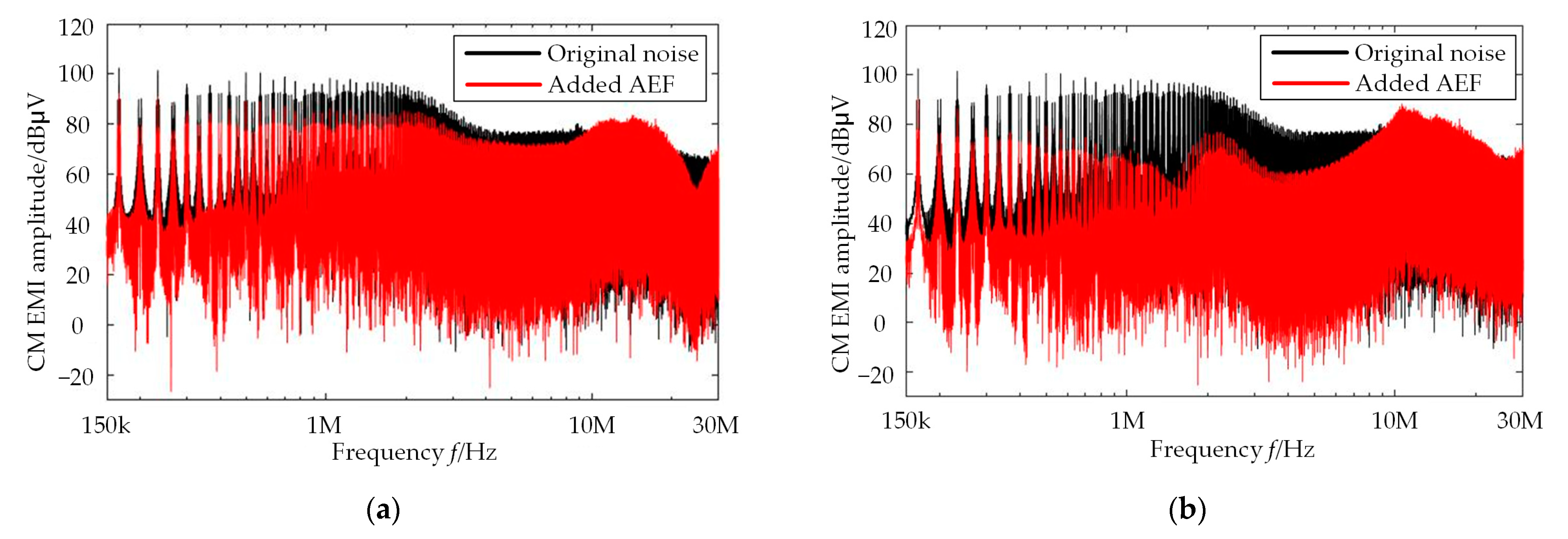
Based on the results in
Figure 20, the CM-conducted EMI spectra of the motor drive system with PCFM–SVPWM combined with the multi-amplification-channel AEF are effectively suppressed in the frequency range of 150 kHz–8 MHz without the addition of passive EMI filter, but the peak amplitudes of some spectra are still high in the frequency range of 10 MHz–30 MHz.
As the low-frequency CM-conducted EMI is effectively suppressed, in order to suppress the CM-conducted EMI in the high-frequency range, only an EMI suppression device for CM-conducted EMI in the frequency range of 10 MHz–30 MHz is required to be added. The Y capacitors of 4700 pF are added to the dc-side of the motor drive system, and the CM-conducted EMI spectra of the motor drive system are shown in
Figure 21. Moreover,
Table 4 lists peak amplitudes of the CM-conducted EMI spectra of partial frequency points depicted in
Figure 20 and
Figure 21.
Based on the results in
Figure 21 and
Table 4, the CM-conducted EMI spectra across the whole frequency range of the motor drive system is effectively suppressed after the Y capacitors are added. Compared with the passive EMI filter, the multi-amplification-channel AEF only occupies a small volume in the whole system because a inductance transformer is not used. Moreover, the PCFM-SVPWM does not change the hardware circuit of the motor drive system; hence, the CM-conducted EMI suppression method of the PCFM–SVPWM combined with the multi-amplification-channel AEF has extensive applications, and the volume and weight of the EMI suppression device is effectively decreased.


