Abstract
This article analyses the problem of automatic balancing rotors with a liquid balancer, which is a cylindrical chamber partially filled liquid of a certain density. This problem is related to the problem of the dynamics of bodies with cavities partially filled with liquid. As part of this task, we analyzed disturbances in the relative motion of the fluid in the ABD chamber caused by the Coriolis force inertia. The distortions of the free surface of the liquid were found, resonant phenomena in the flow of the working fluid were investigated, and the physical explanation of the received results given should be taken into account when designing the corresponding ones self-balancing devices. It was established that the axial component of the Coriolis inertial force causes peculiar wave phenomena in the correcting fluid movement. For the given nature of undisturbed motion, the conditions of this phenomenon’s occurrence are determined only by the geometric dimensions of the cylindrical chamber and the thickness of the liquid layer in undisturbed motion, and do not depend on the intensity of rotation of the liquid, nor on its density. It is shown that a decrease in the “ABD chamber height–radius” ratio leads to stabilization of the movement of the system. Experimental verification has been performed; theoretical results on the developed stand for work research rotor system with a vertical axis of rotation.
1. Introduction
Nowadays, rotating machines and mechanisms are used in various mechanical systems of the mining, processing, and energy industries. A common problem here are vibrations caused by mass imbalances. For modern industry, vibration protection is important and commercially profitable, as it allows for increasing the machine speed, contributes to the extension of their life cycle, and prevents occupational hazards to personnel.
During the manufacturing of rotors, due to errors in mechanical processing and assembling of parts, material inhomogeneity, as well as due to deformation (curvature), wear, and local destruction during their operation, the exact “rotors axis of inertia–actual axis of inertia of their rotation” alignment is not practically ensured. Imbalance can also be caused by maintenance problems (deformation or contamination of pumps, compressors, fans, turbine blades, etc.) [1,2], rotor repairs, or restorations using protective coatings or functional coatings [3,4].
In any rotating body, in particular rotors, the axis of rotation that does not coincide with one of its main axes of inertia generates a motion-induced (dynamic) load on the supports; that is, it exerts some variable disturbance on the supports [5]. Accordingly, the resulting “static” imbalance is either eliminated in the technological operation balancing, or is compensated for directly during operation without stopping the rotors by automatic balancing mechanisms [5,6]. The expediency of self-balancing the rotors become obvious if the imbalance is stochastic, constantly and/or rapidly changing due to the machine features, or when stopping the rotor is undesirable or unacceptable under operating conditions.
Self-balancing systems are divided into two types: active and passive. In active ABD, the corrective masses move forcibly, in a passively free manner under the action of internal forces; their work is carried out due to the energy of the rotor itself. Active devices include devices with forced movement or change in rotor masses, as well as forced centering devices [7,8,9,10,11].
Passive ABDs are direct-action regulators, and do not require power supply and creation of control systems to move the corrective masses, they have sufficient sensitivity to changes in imbalance, and their application does not require rotor oscillation form information [12,13]. The most studied passive self-balancing devices are mechanical ones, but they have a number of general shortcomings, and are not yet widely used in technology. The main reasons are twofold: their noisy operation and their corrective loads (rings, balls, segments, and pendulums) act on the rotor or on the elements of the ABD itself with significant forces [14,15].
Liquid passive automatic balancing devices do not have these disadvantages. The liquid ABDs of the Le Blanc type are self-balancing devices based on hoop-shaped cavities partially filled with liquid. They do not cause wear of operational surfaces, are reliable and silent in operation, simple, cheap to manufacture, unpretentious in operation, easy to maintain, environmentally friendly, and intrinsically safe; the body of the balancer can hug the rotor from the outside, which frees up the inner space of the rotor. However, liquid-type ABDs have been studied to a lesser extent and, due to this fact, they are even less often used in practice.
Leblanc M. [16], Thearle E. [17], Dyer J. [18], and Remer J. [19] dealt with the problems of automatic balancing of machine rotors by passive ABD at different times. Den Hartog J.P. scientific schools are well-known in the field of self-balancing and rotor vibration protection [20] (see also Strautmanis G. et al. [21], Rodrigues D. et al. [22], and Filimonikhin G.B. et al. [23]). Representatives of these schools conduct theoretical and experimental studies of Jeffcott rotor dynamics with an ABD mechanical type. Theoretical approaches are based on the analysis of nonlinear equations of motion, dynamic stability, and the behavior of mechanical corrective masses.
The first attempts to justify theoretically the passive self-balancer operation principle, regardless of the aggregate state of the used corrective masses, are associated with Thearle E. They are described in a series of articles [24], which are the first review of passive ABD design development ideas proposed for balancing mainly vertically located drums of washing machines.
Thearle E. proposed a planar rotor model with ABD. Within this model, the rotor has one critical speed, above which it rotates with the light side out. Thus, the principle of operation of all passive autobalancers of the Thearle E. design is based on the phenomenon of self-centering, which occurs for flexible rotor systems in a closed range of rotation speeds, regardless of the presence of an autobalancer in the system. Thearle E., in his studies, used the kinetostatic or quasi-static method, assuming that transient processes almost do not affect the movement of rotors with the ABD. Therefore, the movement of the system is presented as a rotation around the axis of a rigid body; the correcting fluid reacts very slowly to the forces acting on it, and eventually reaches a position of relative equilibrium only in a closed range of system rotation frequencies.
According to these assumptions, instead of the hydrodynamic equations of motion of the rotor with liquid ABD, the equations of kinetostatics are formulated. According to the results of this approach, all devices, in particular those of the liquid type, are capable of operating at speeds greater than the critical one. The practical experience of using liquid ABDs shows that theoretical conclusions are not confirmed in real systems.
A number of works based on the theoretical approaches developed by Thearle E. [24] and Conrad D.C. [25] are devoted to the dynamics of the liquid self-balancing devices, which are used as part of the household washing machines. The authors [25] analyzed an ABD with several chambers in the form of successive concentric annular cavities, which were supposed to increase the balancing properties of the liquid. Suzuki S. et al. [26] developed a numerical model of mass distribution in a washing machine with a liquid balancer. Mitsuishi, M. et al. [27] estimated the force generated by the fluid balancer from the observed load values for the entire rotating structure. Bae S. et al. [28] built equations of vertical-radial washing machine motion. However, the rotating chamber and drum were represented as two rigidly connected rigid elements, which limited their movements. Jung C.H. et al. [29] proposed a liquid ABD with partitions, and a method of calculating the dynamics of fluid motion was used to verify its effectiveness. Urbiola-Soto L. and Lopez-Parra M. [30], for the first time, showed experimental and analytical data to understand the movement of the fluid flow inside the balancing ring chamber and its interaction with the partitions. Langthjem M. and Nakamura T. [31] established the damping effect of the working fluid in the ABD chamber, which is produced by a surface wave. The thin internal fluid layer, which forms due to the rotation, is described in terms of shallow water wave theory. In their article, Li B. et al. [32] considered the dynamic stability of a rigid rotor with a liquid ABD.
During the study of rotor systems with liquid, an important class of problems in the dynamics of bodies with cavities containing a liquid arises. The problems of the rotor system with liquid dynamics are of interest from a general theoretical point of view. This problem stimulates the development of research methods that allow taking into account the joint action of factors such as rotation, the presence of a free surface and the viscosity of the liquid, and the support reaction, as well as the drive that supports the rotation. At the same time, the specific results of the study of the aforementioned system dynamics are of independent interest, in particular for the development and creation of various designs of rotary machines (separators, liquid gyroscopes, ultracentrifuges, turbines cooled by liquid from the inside, etc.) and ABD for their automatic balancing.
In the study of Ehrich F. [33], based on a fairly simple simulation, it was concluded that, in the case of synchronous rotation of the rotor with a small amount of trapped liquid (but a completely wetted cavity wall), the behavior of the rotor is equivalent to the rotation of a rotor completely filled with liquid. This indicates that the liquid-type balancer cannot work under the action of synchronous precession. Its operation should be based on the action of asynchronous precession, at least if the wall of the cavity is completely wetted by liquid. This assumption is supported by the fact that the correction fluid tends to move away from its “best” position in the chamber to initiate the balancing process [30].
In many studies devoted to the dynamics and stabilization of rotors partially filled with liquid, much attention is paid to the peculiarities of liquid dynamics. The works of Bolotin V.V. [34], Crandall S.H. [35], Derendyaev N. et al. [36] and Zili Z. et al. [37] are meaningful reviews of these issues.
Most studies, such as the works of Wolf Jr. [38], Hendricks S. and Morton J. [39], Holm-Christensen O. and Traäger K. [40], are based on the linear theory of the dynamics of a rotor system with a liquid. Such an approach is quite sufficient for determining the stability of motion, but is insufficient for modeling and understanding the dynamics of fluid balancing.
Berman A. et al. [41], Chato D. and Dalton P. [42] and Yoshizumi F. [43] used nonlinear models. Berman A. et al. [41] applied numerical analysis and an experiment focusing on the case of asynchronous precession, and found that nonlinear surface waves can exist on the liquid layer in the form of relatively weak hydraulic jumps with waves generated by it. Similar studies by Chato D. and Dalton P. [42] and Yoshizumi F. [43] are purely experimental and numerical.
In papers [44,45], a quasi-static approach to the problems of dynamic deformation of shells partially filled with an elastic filler was implemented, and in articles [46,47], modal analysis and parametric optimization of such systems were carried out.
Problems of the movement of rotating bodies with cavities partially filled with liquid, in relation to the problem of self-balancing, are considered in a rather limited number of works.
Nakamura T. [48] and Thompson-Salinas A. et al. [49] conducted experimental studies of the liquid balancing process. The work of Nakamura T. [48] shows the influence of the liquid in the chamber of the rotating rotor on the automatic balancing of the mechanical system, without taking into account the forces of internal resistance using elementary modeling. Thompson-Salinas A. et al. [49] determined the influence of various design factors on the efficiency of liquid ABD for an automatic washing machine during transient and stable modes of operation.
The main result of the study by Wesley V. and Cunico M. [50] is the construction and analysis of a numerical model that describes the operation of a liquid ABD of the Le Blanc type in the transient mode of operation. As a result, the behavior of the balancing fluid was determined in the Computational Fluid Dynamics tool, and an equation was found that describes the restoring force, imbalance, containing the force phase and eccentricity.
Some results of numerical modeling based on computational fluid dynamics are presented in the works of Jung C.H. et al. [51], Cho Jung-Soo Chen H.-W. and Zhang, Q.-J. [52].
The simplest models of concentrated masses were considered by Urbiola-Soto L. and Lopez-Parra M. [30], Majewski T. [53], Chen Hai-Wei Cho J.-S. et al. [54]. These articles also contain the results of experimental studies of the liquid balancing process for an automatic washing machine with a vertical axis. Royzman V. et al. [55] investigated the movement of the liquid, taking into account the angle of inclination of the axis of the rotor with the ABD chamber relative to the horizon line. Analytical dependences of residual deflections on the angle of inclination were obtained, and it was proved that as the angle of inclination increases, the residual deflections of the rotor decrease in absolute value.
Research by Langthjem M. and Nakamura T. [31] is based on the idea of Berman A. et al. [41], and uses the provisions of the theory of waves in shallow water. The result is an (approximate) analytical solution of the fluid dynamics equations obtained using the perturbation approach. Thus, the authors explain the mechanics of the liquid balancer using simple equations in an explicit form.
In our previous studies [56], a flat model of the problem of wave formation on the liquid surface in the chamber of a liquid self-balancing device was considered. The existence of a zone of instability near the critical speed of rotation of the rotor has been proven, based on the analysis of the frequency equation of the system of differential equations, which describe the movement of the rotor installed in elastic supports, rotating with a liquid self-balancer. Getting a fluid balancer to work flawlessly is a delicate process, so a more detailed understanding of the balancer’s hydrodynamics is desirable.
The purpose of this work is to study steady-state disturbances in the relative motion of the fluid caused by the volumetric Coriolis force of inertia, to study the resonance phenomenon in the flow of the working fluid, and to provide a physical explanation for the obtained results, which must be taken into account during the design of self-balancing devices.
The main tasks of the work are:
- -
- Study the peculiar wave processes propagating in an incompressible liquid that rotates uniformly in a closed cylindrical chamber;
- -
- Detection of effects and phenomena associated with the action of Coriolis forces of inertia;
- -
- Substantiation of the impact of these phenomena on the operation of the liquid autobalancer and its design parameters;
- -
- Performing experimental verification of the results of theoretical studies on a specially designed experimental stand for studying the operation of a rotor system with a vertical axis of rotation.
2. Materials and Methods
This section provides a description of the methodology for conducting experimental and theoretical studies, which were carried out in order to verify the mathematical model of fluid movement dynamics in the liquid-type autobalancer chamber. The existence of instability zones in the rotation of the rotor, and the dependence of their ranges on the degree of filling of the ABD chamber with liquid and geometric dimensions, are shown with cameras in the autobalancer in the case of movement of a rotor system with a vertical axis of rotation.
2.1. Experimental Equipment
Experimental studies were carried out with the measurement of amplitudes of rotor oscillations of a specially designed experimental setup (Figure 1).
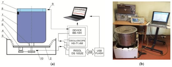
Figure 1.
Scheme (a) and general view (b) of an experimental stand with an experimental setup for researching a rotor system with a vertical axis of rotation: 1—drum (rotor); 2—platform; 3—bearing housing; 4—elastic elements; 5—body; 6—electric motor; 7—ABD; 8—imbalance; 9—inductive sensor; 10—speed marker.
Equipment for experimental research has the following technical characteristics:
- (1)
- An experimental sample of the self-balancing device (cylindrical ring h = 50 mm high with an outer radius R = 200 mm, and two concentric partitions of radii R = 150 and R = 100 mm, forming three concentric chambers for placing the corrective (working) fluid in them). Three chambers are hermetically isolated. This makes it possible to investigate the dependence of the efficiency of the autobalancing process on the geometric dimensions of the camera;
- (2)
- Working fluid–fresh water (density 1.00 × 10³ kg/M3, kinematic viscosity 1.01 × 10⁻⁶ m2/s at a temperature of 20 °C);
- (3)
- The experimental unit was developed on the basis of a drum-type washing–squeezing machine. The rotor is a drum that is rigidly fixed on the axis of rotation. On the upper edge of the drum, with the help of fasteners, a sample of the autobalancer is rigidly fixed, which ensures the coaxiality and sufficient rigidity of the rotor. The rotor axis is connected to the rigid platform through rolling bearings. The platform is connected to the body of the installation by four elastic damping suspensions. For the experimental setup, the following empirical logarithmic attenuation decrement = 0.854 was determined, and the damping coefficient n = 7.06.
The rotor is driven by an electric motor through a V-belt transmission. The engine is powered by alternating current, the voltage of which varies in a fairly wide range using an autotransformer with a control system. This made it possible to set:
- -
- Rotary movement of the rotor system, with different rotor rotation speeds in the range of 30–1080 rpm;
- -
- Different angular accelerations during acceleration (coasting) of the rotor;
- -
- The time of constant rotation in the pre-resonance, resonance, and post-resonance zones of the rotor rotation for detailed studies of the operation of the liquid autobalancer.
With the help of a measuring stand, which consists of measuring and recording equipment, the research of oscillations of the experimental installation was carried out. A non-contact inductive sensor (Figure 2a) was used to measure the range of movements of the upper edge of the rotor.
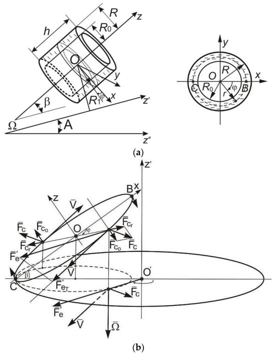
Figure 2.
Graphical explanation of the arrangement of forces in the problem of fluid dynamics rotating in the autobalancer chamber: (a) calculation scheme of the ABD chamber with liquid; (b) volumetric transfer () and Coriolis () inertial forces and their projections acting on liquid.
To measure the speed of the rotation of the drum, a specific marker of revolutions was used in the form of a small ferromagnetic plate, which was installed on the end of the pulley of the drum. For each rotation of the drum, the plate crossed the magnetic lines of force of the sensor, which is designed on the basis of the Hall sensor (Figure 2a), once.
A RIGOL DS1052E digital oscilloscope was used to observe and measure the waveform parameters, which has the ability to save data images as a file with the BMP extension or event table data as a CSV (tabulated) format file that can be edited in Excel through the USB port. Research was carried out by:
- -
- A step-by-step increase in the mass of the simulated imbalance (from 50 g to 250 g), which was placed on the inner wall of the drum near the free edge (the imbalance of the rotor D was from 1000 g∙cm to 5000 g∙cm);
- -
- A step-by-step increase in the liquid volume (from 50 mL to 450 mL) in chambers of different radii (R = 200 mm; 150 mm; 100 mm).
The table file recorded the data of the vibrodisplacement tank during rotor rotation at constant speeds: from ω = 150 rpm. up to 400 rpm—pre-resonance zone, from 490 to 570 rpm—resonance zone, over 800 rpm—post-resonance zone; amplitude-frequency characteristics were constructed.
The representativeness of the experimental data has been substantiated through multiple repetitions of trials (10–15 times), followed by the processing of measurement results using standard methods of mathematical statistics. The errors in the experimental results did not exceed 10%.
Based on the results of recording the vibrations of the upper edge of the drum during its movement, graphical dependences of the amplitude of the rotor oscillations on the volume of liquid in the autobalancer chamber were constructed.
2.2. Mathematical Model of the Dynamics of the Liquid Rotating in the Cylindrical Chamber
The formulation of the basic theory of wave processes is based on the approach of Blekhman I.I. [57]. But, instead of relying on the approach of numerical integration, we find an (approximate) analytical solution of the hydrodynamic equations of the liquid, which makes it possible to determine the curvature of the free surface of the liquid, to investigate resonance phenomena in the flow of the working fluid, and to provide a physical explanation of the obtained results, which must be taken into account when designing the corresponding self-balancing devices.
Consider a closed chamber ABD, having the shape of a straight circular cylinder of radius R and height h, partially filled with an ideal incompressible liquid of density ρ (ρ = const). Suppose that, in the absence of volumetric forces, the liquid carries out a steady circular motion, and is located in the chamber in the form of an annular layer with a thickness of R–R0 (Figure 2).
Let us introduce dimensionless cylindrical coordinates η = r/R, φ, ζ = z/R. Then, the equalities:
are, respectively, expressions of the dimensionless flow rate, pressure, and free surface equation for arbitrarily specified functions v0(η) and values p00.
Let the camera rotate with a constant angular velocity around some axis , that is inclined to the horizon line at an angle A , which lies with the axis of the chamber in one plane and forms an angle with it β (β ≠ 0). The task is to study steady-state disturbances in the relative motion of the fluid caused by volumetric transfer and Coriolis forces of inertia. This problem arises when investigating the operation of a liquid ABD in an unbalanced system (with complete equilibrium, we have β = 0).
The Euler and incompressibility equations have the form:
where —fluid velocity relative to the chamber ABD; p—pressure; parameters , ; , —transfer and Coriolis acceleration; —velocity scale, the maximum value of the modulus of the fluid circular velocity. Parameter ε consider small, which corresponds to the ratios that are characteristic of the studied devices.
Note that Equation (2) is actually a gradient equation, in other words, an equation with the derivative of the function (in this case, the pressure and the square of the flow rate) in the direction of the greatest growth. However, situations may arise when it is necessary to describe processes in directions other than the direction of the gradient, then it is necessary to use differential equations with derivatives in the direction, the mathematical apparatus for which was developed in [58,59].
Let us present the equation of the free surface in the form F(η, φ, ζ) = η − ψ(φ, ζ) = 0, and we will write down the boundary conditions of the problem, as well as the periodicity conditions of the sought quantities by the angular coordinate φ and the conditions for the balance of the volume occupied by the liquid:
We will look for the solution to problems (2)–(5), which belong to the class of inverse boundary value problems, in the form of series by powers of a small parameter ε:
Substitution of expression (6) into Equation (2) and condition (5) leads to the following relations:
- -
- To find the initial approximation to the solution of the problem:
- -
- To find the first approximation to the solution of the problem:
Expression (1) is the solution of problem (7).
Taking into account expression (1), equality (9) and, obtained by Formula (4), the equalities (where —arbitrary function), we write relation (8) for finding the first approximation in the form:
The linearity of problems (10)–(12) makes it possible to break them down into four independent problems, which correspond to flow disturbances by different components of inertial forces in relative motion.
3. Results and Discussion
Let us consider the problem that models the perturbation of the fluid flow caused by the axial component of the Coriolis inertial force.
This problem consists of solving Equations (11) and (13) under these conditions:
Figure 3 illustrates the nature of the considered disturbing influence, which tries to “rock” the rotating liquid. The perturbations arising here are not flat and axisymmetric.
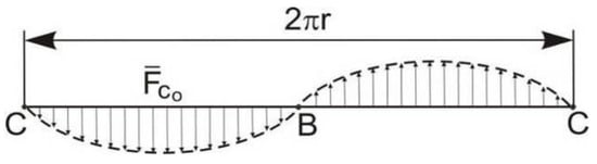
Figure 3.
The nature of the disturbing influence of the axial components of the volume forces of Coriolis inertia.
Substitution:
where U, V, W, P and —unknown functions, allowing you to exclude the variable φ from the equations and boundary conditions. We have:
Let , where D—constant. We reduce the system of Equation (15) to a linear differential equation in the partial derivatives of the second order for the function :
Using conditions (16) and Equation (15), we find the boundary conditions that the function must satisfy P:
Note that the coefficients a(η), b(η) and c(η) become constants if v0 = Bηγ, where B and γ—constants. For simplification, let us take . Functions v0 of this type allow us to cover a fairly wide class of practically important cases, including the case of a quasi-rigidly rotating fluid, which corresponds to the value γ = 1. As a result of substitution (γ ≠ –1/2) in Equation (17) and condition (18), we have the boundary value problem:
associated with an equation of the hyperbolic (for γ > −1/2) or elliptic (for γ < −1/2) type. If the variables are separated, we will consider and, having denoted by −μ2 the separation constant, we will arrive at the regular Sturm–Liouville problem with the conditions:
and the equation: .
We apply the Fourier method [60] and come to the solution of the problem for the case γ > −1/2 in the form:
where μn—the roots of the equation are numbered in order of increasing eigenvalues of μn2;
where Jr(x) and Yr(x) Bessel functions of the first and second order r;
Let us analyze solution (19). The equation of the free surface, curved as a result of the disturbance being studied, according to (6) and (9), has the form:
Therefore, all intersections ζ = const of the curved free surface remain with the considered accuracy circles of radius η0, and the axial line of the surface is the curve x = εN(ζ), lying in the plane zz′.
Note that when performing inequalities and ratios
we have ; then ; therefore, the n-th terms of all series in the solution (19) turn into infinity. Since the numbers μn2 since , respectively, depend only on the parameters η0 and γ, and equality (22) establishes, at a fixed γ for each number n and number k, some dependence between the geometric parameters η0 = and .
Let us call the set of dependencies (22) resonance relations. Note that the character of the perturbed action gives reason to determine that the phenomenon of resonance during forced oscillations of the rotating liquid layer really occurs here. Naturally, the transformation of the sought values into infinity when performing resonance ratios is connected only with the use of the ideal fluid model. When using the model of a viscous liquid, the perturbations at resonances would have finite values [57,61]. In the vicinity of resonances, there will only be an increase in perturbations, which is most pronounced only for “low-order” resonances, i.e., those that correspond to small values of n [57]. This is partly due to the fact that the coefficients of the members of series (19), taking into account (20) for , decrease with increasing of n like . Thus, only a few first resonances are of practical interest. And it is possible to obtain the correct information about the nature of the flow, keeping only a small number of terms in the series (19).
The considered resonance phenomena have the following features. The conditions for their occurrence with a given nature of the distribution of circular velocities in undisturbed motion are determined by the relationships only between the geometric parameters of the system (i.e., the height of the chamber, its radius, and the radius of the free surface), and do not depend on the intensity of the fluid rotation, not from its density. We can offer the following physical explanation of this conclusion: during rotation, the liquid layer acquires a kind of stiffness proportional to the value ρ·ω, where ω is the angular velocity of the liquid rotation around the axis of the chamber z. As a result, the frequency of free oscillations of the liquid layer λi is independent of ρ and proportional to the value ω, which coincides in the case with the disturbance frequency, but then ω in resonance relations of the type ω = λi is shortened, and the density of the liquid ρ is not included in them.
In Figure 4, at γ = 1 and for two combinations of parameters corresponding to experimental samples of ABD liquid type: η0 = = and = ; η0 = = and = curves characterizing the curvature of the axis of the free surface of the working fluid are shown.
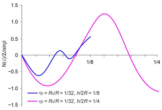
Figure 4.
Curves characterizing the curvature of the axis of the free surface of the working fluid in the autobalance bar for various parameters.
The first combination corresponds to a significant distance from the main resonance zones, and the second to an approach to the first resonance zone. Thus, it is proven that the stable behavior of the working fluid has a direct dependence on the geometric dimensions of the ABD chamber; namely, an increase in the radius of the ABD chamber increases the efficiency of self-balancing. This result was also obtained in the process of experimental research.
The considered waves are inertial. Since Coriolis forces do no work on the moving fluid, the energy contained in these waves is completely kinetic. Note that when β = 0, i.e., when the axis of the chamber coincides with the axis (or is parallel to the axis) around which it rotates (exactly during self-balancing), the axial component of the Coriolis force is absent and resonance phenomena of the liquid are impossible.
The results of this theoretical study allow us to hypothesize that the operation of the rotor system with liquid ABD is more stable if the height of the chamber h is much smaller than its radius R.
An experimental proof of this assumption is presented below. The results of the research conducted on the experimental stand (Figure 1) with simulated rotor imbalance D = 3000 g∙cm are presented in Figure 5.
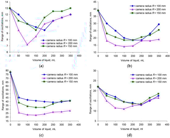
Figure 5.
Range of oscillations of the upper edge of the drum for different volumes of working fluid in ABD at relative angular speeds of rotation: (a) 0.6ωp (pre-resonance mode, beginning of effective balancing); (b) 0.8ωp (pre-resonance mode, effective balancing); (c) when passing through resonance ωp; (d) 1.2ωp (resonant mode).
Based on the results of recording the vibrations of the upper edge of the drum during its movement, we generated graphical dependences of the amplitude of the rotor oscillations on the volume of liquid in the autobalancer chamber. The empirical efficiency coefficient of automatic balancing was also calculated as the ratio of the swing of the rotor without liquid in the ABD chamber to the value of the swing when the chamber is filled with liquid. To obtain adequate data on the value of the balancing efficiency coefficient, all tests under certain conditions were repeated 10–15 times. With the application of mathematical statistics methods, the averaged values of the efficiency coefficients of liquid ABDs were obtained.
The analysis of graphical dependencies (Figure 5a–d) indicates that, for a vertical rotor installation over the entire range of angular velocities of the system:
- (1)
- There is a sufficient volume of working fluid to balance the system, which creates an imbalance approximately equal to the imbalance of the rotor. Partially, for a chamber with a radius of 200 mm (h/2R = 1/8), it is 100 mL, for a chamber with a radius of 150 mm—150–200 mL, and for a chamber with a radius of 100 mm (h/2R = 1/4)—150–200 mL, with an imbalance mass of 150 g. The greatest balancing effect is achieved when the amount of liquid imbalance is close to the amount of simulated imbalance;
- (2)
- The range of rotor oscillations increases when the condition of fluid sufficiency is not met and the degree of chamber filling increases;
- (3)
- The effectiveness of liquid balancing is obvious (values of the range of oscillations of the upper edge of the drum, corresponding to V = 0 mL, significantly decrease when adding liquid);
- (4)
- The geometric parameters of the cavity have a significant influence on the efficiency of liquid self-balancing.
The last statement is illustrated by the data in Table 1, which were obtained for a simulated rotor imbalance value of 2000 g∙cm.

Table 1.
Values of averaged empirical coefficients of balancing efficiency at optimal filling of chambers ABD with different radius.
The analysis of the data in the table indicates that an increase in the chamber radius by 30% and by 100% leads to a decrease in the range of rotor oscillations at 0.6ωp (pre-resonance mode, the beginning of effective balancing) by 5.71%; when passing through resonance ωp, by 7.58% and 20.74%, respectively; at 1.2ωp (resonant mode) by 13.48%.
Analysis of research results at a simulated imbalance of 3000 g∙cm. (Figure 5a–d) make it possible to conclude that when the volume of the correction fluid is sufficient, effective balancing is observed over the entire range of the investigated angular velocities of rotation of the vertical rotor system. Additionally, the trend of increasing balancing efficiency in the vicinity of resonance is preserved for research with different ABD cameras. Thus, increasing the radius of the chamber by 30% and by 100% leads to a decrease in the range of rotor oscillations at 0.6ωp (pre-resonance mode, the beginning of effective balancing) by 30.56% and 33.33%, respectively; at 0.8ωp (pre-resonance mode, effective balancing) by 42.86% and 57.14%; when passing through resonance ωp by 37.50% and 66.67%; at 1.2ωp (resonant mode) by 27.27%.
Thus, the operation of the rotor system with liquid ABD is more stable, provided that the height of the chamber h is much smaller than its radius R. We obtained a similar result in previous studies [62], where the basis for modeling the motion of the rotor system with liquid ABD is defined by the principle of least action in the form of Hamilton–Ostrogradsky.
When calculating the self-balancing device for the cases of a rotor with a horizontal axis and an axis inclined at an angle to the horizon line, the problem arises of the planar steady motion of a layer of heavy liquid in a cylinder that rapidly rotates around its axis. It is especially important to determine the shape of the free surface of the liquid under these conditions. It is clear that this problem is similar to the part of the considered problem that is modeled in the framework of an ideal fluid by problems (2)–(5) with , and γ = 1, β = 0, A = 0. The solution, analysis and experimental verification of the solution we see as a direction for future research.
The results of the application of the proposed mathematical model of fluid dynamics in the ABD chamber with the introduced fluid viscosity parameter may also be interesting. We initiated experimental studies of the working fluid viscosity effect on the self-balancing process in [61].
It is essential to note that the experimental investigations were conducted with the measurement of rotor oscillation amplitudes of the test setup and with direct visual observation of the position of the working fluid in the ABD chamber relative to the imbalance during system rotation. The results of the visual examinations are partially presented in the authors’ previous works [62,63], and align well with the findings obtained in this study.
The application of a new approach for the analysis and verification of experimental data using the Teager–Kaiser energy operator (TKEO) can also be beneficial. This method, developed by Kaiser in 1990, involves a straightforward calculation of signal energy. In [64], a comprehensive analysis of the application domains of this method is provided, specifically noting that the energy operator can be employed in the automatic rotor balancing process.
4. Conclusions
Disturbances of the relative motion of the liquid in the ABD chamber, caused by volumetric Coriolis forces of inertia, were analyzed; distortions of the fields of velocities, pressures and the free surface of the liquid were found; and resonant phenomena in the flow of the working fluid were investigated. It is shown that the axial component of the Coriolis inertial force causes peculiar wave phenomena in motion. The conditions for the occurrence of which are determined by the given nature of undisturbed motion only by the geometric dimensions of the cylindrical chamber and the thickness of the liquid layer in undisturbed motion, and do not depend on the intensity of rotation of the liquid or from its density.
It has been theoretically proven that the operation of the rotor system with liquid ABD is more stable if the height of the chamber h is much smaller than its radius R.
An experimental verification of the results of theoretical studies was carried out on a specially designed experimental stand for studying the operation of a rotor system with a vertical axis of rotation. In particular, it is defined:
- -
- The presence of a sufficient volume of working fluid for effective balancing, and the greatest balancing effect is achieved when the amount of fluid imbalance is close to the amount of simulated imbalance;
- -
- An increase in the degree of filling the chamber with liquid leads to an increase in the range of oscillations of the rotor system;
- -
- An increase to the council ABD camera mouth provides a significant increase in balancing efficiency.
Author Contributions
Conceptualization, I.D. and L.R.; methodology, I.D., V.L. and T.S.; software, I.D.; validation, I.D. and T.S.; formal analysis, I.D. and L.R.; investigation, I.D.; resources, I.D. and V.L.; data curation, I.D.; writing—original draft preparation, I.D.; writing—review and editing, I.D. and L.R.; visualization, I.D., L.R. and T.S.; supervision, L.R. and V.L.; project administration, L.R. and V.L.; funding acquisition, V.L. All authors have read and agreed to the published version of the manuscript.
Funding
This study was carried out as part of the project “Belt and Road Initiative Centre for Chinese-European studies (BRICES)” and was funded by the Guangdong University of Petrochemical Technology. This research was funded by the Ministry of Education and Science of Ukraine for the grant to implement projects 0122U002082 and 0123U101858.
Data Availability Statement
The data are contained within this article.
Acknowledgments
The authors express their sincere gratitude and respect to the Armed Forces of Ukraine, who made it possible to complete the preparation of this article for publication. The authors are also grateful to the editor and reviewers for their comments that helped improve the content of this paper.
Conflicts of Interest
The authors declare no conflicts of interest.
Nomenclature
The following symbols are used in this manuscript:
| R | radius chamber ABD |
| H | height chamber ABD |
| ρ | liquid of density |
| R | R0 thickness of an annular layer of liquid |
| η0 | coefficient characterizing filling of the chamber with liquid |
| z | axis of the chamber |
| axis around which the camera rotates | |
| Β | angle of deviation of axis z from axis |
| R1 | radius of chamber rotation around axis |
| η = r/R, φ, ζ = z/R | dimensionless cylindrical coordinates |
| chamber ABD angular velocity | |
| fluid velocity relative to the chamber ABD | |
| P | pressure |
| ε, δ | parameters |
| transfer acceleration | |
| Coriolis acceleration | |
| velocity scale |
References
- Blanco-Ortega, A.; Silva-Navarro, G.; Coln-Ocampo, J.; Oliver-Salazar, M.; Vela-Valds, G. Automatic Balancing of Rotor-Bearing Systems; IntechOpen Limited: London, UK, 2012. [Google Scholar] [CrossRef]
- Li, L.; Cao, S.; Li, J.; Nie, R.; Hou, L. Review of Rotor Balancing Methods. Machines 2021, 9, 89. [Google Scholar] [CrossRef]
- Prysyazhnyuk, P.; Molenda, M.; Romanyshyn, T.; Ropyak, L.; Romanyshyn, L.; Vytvytskyi, V. Development of a hard banding material for drill pipes based on high-manganese steel reinforced with complex carbides. Acta Montan. Slovaca 2022, 27, 685–696. [Google Scholar] [CrossRef]
- Ropyak, L.; Shihab, T.; Velychkovych, A.; Bilinskyi, V.; Malinin, V.; Romaniv, M. Optimization of Plasma Electrolytic Oxidation Technological Parameters of Deformed Aluminum Alloy D16T in Flowing Electrolyte. Ceramics 2023, 6, 146–167. [Google Scholar] [CrossRef]
- Ishida, Y.; Yamamoto, T. Linear and Nonlinear Rotordynamics: A Modern Treatment with Applications, 2nd ed.; Wiley-VCH Verlag & Co.KGaA: Weinheim, Germany, 2012; p. 447. [Google Scholar] [CrossRef]
- Osinski, Z. Damping of Vibrations, 1st ed.; CRC Press: Boca Raton, FL, USA, 2018; Available online: https://www.perlego.com/book/1491406/damping-of-vibrations-pdf (accessed on 14 October 2023).
- Chen, H.-W.; Yuan, X.-T.; Zhen, S.; Mou, Q.-Q.; Xiong, M.; Wang, W.-H. Design and Analysis of an Active Balancing Mechanism for a Vertical Axis Washing Machine. Int. J. Precis. Eng. Manuf. 2022, 23, 763–778. [Google Scholar] [CrossRef]
- Pan, X.; He, X.; Wei, K.; Wu, H.; Gao, J.; Jiang, Z. Performance Analysis and Experimental Research of Electromagnetic-Ring Active Balancing Actuator for Hollow Rotors of Machine Tool Spindles. Appl. Sci. 2019, 9, 692. [Google Scholar] [CrossRef]
- Xu, X.; Fan, P.P. Rigid Rotor Dynamic Balancing by Two-plane Correction with the Influence Coefficient Method. In Applied Mechanics and Materials; Trans Tech Publications Ltd.: Wallerau, Switzerland, 2013; Volume 365, pp. 211–215. [Google Scholar] [CrossRef]
- Fan, H.W.; Jing, M.Q.; Wang, R.C.; Liu, H.; Zhi, J.J. New electromagnetic ring balancer for active imbalance compensation of rotating machinery. J. Sound Vibr. 2014, 333, 3837–3858. [Google Scholar] [CrossRef]
- Pan, X.; Xie, Z.; Lu, J.; Wu, H.Q.; Gao, J.J.; Jiang, Z.N. Novel Liquid Transfer Active Balancing System for Hollow Rotors of High-Speed Rotating Machinery. Appl. Sci. 2019, 9, 833. [Google Scholar] [CrossRef]
- Strautmanis, G.; Filimonikhin, G.; Mezitis, M.; Gorbenko, A.; Strautmane, V.; Sansyzbajeva, Z. Modelling of transient and steady-state modes of a vertical rotor with an automatic balancing device. J. Vibroeng. 2021, 23, 759–769. [Google Scholar] [CrossRef]
- Gorbenko, A.N.; Klimenko, N.P.; Strautmanis, G. Influence of Rotor Unbalance Increasing on its Autobalancing Stability. Procedia Eng. 2017, 206, 266–271. [Google Scholar] [CrossRef]
- Chung, J.; Ro, D.S. Dynamic analysis of an automatic dynamic balancer for rotating mechanisms. J. Sound Vibr. 1999, 228, 1035–1056. [Google Scholar] [CrossRef]
- Pan, X.; Ge, D.; Li, W.; Huo, J. Research on Pneumatic–liquid On-Line Automatic Balance Technology for High-End Turbine Units. Machines 2022, 10, 744. [Google Scholar] [CrossRef]
- Leblanc, M. Automatic Balancer for Rotating Bodies. U.S. Patent US71117712A, 26 December 1916. Available online: https://www.google.com/patents/US1209730 (accessed on 20 December 2022).
- Thearle, E. A new type of dynamic-balancing machine. Trans. ASME (Appl. Mech.) 1932, 54, 131–141. [Google Scholar] [CrossRef]
- Dyer, J. Domestic Appliance. U.S. Patent US2375635A, 8 May 1945. Available online: https://www.google.com/patents/US2375635 (accessed on 18 November 2023).
- Remer, J. Balancing of Rotatable Bodies. U.S. Patent US2525781A, 17 October 1950. Available online: https://patents.google.com/patent/US2525781A/en?inventor=Remer+Jay+Grant+De (accessed on 18 November 2023).
- Den Hartog, J.P. Mechanical Vibrations; Dover Publications: New York, NY, USA, 1985; Available online: http://www.freading.com/ebooks/details/r:download/ZnJlYWQ6OTc4MDQ4NjEzMTg1Njpl (accessed on 18 November 2023).
- Strautmanis, G.; Mezitis, M.; Strautmane, V.; Gorbenko, A. Impact of dimensions of the compensating mass of the automatic balancer on its acceleration. Vibroeng. Procedia 2017, 12, 1–5. [Google Scholar] [CrossRef][Green Version]
- Rodrigues, D.; Champneys, A.; Friswell, M.; Wilson, R. Automatic two-plane balancing for rigid rotors. Int. J. Non-Linear Mech. 2008, 43, 527–541. [Google Scholar] [CrossRef]
- Filimonikhin, G.; Nevdakha, Y. Balancing a Rotor with Two Coupled Perfectly Rigid Bodies. Int. Appl. Mech. 2002, 38, 377–386. [Google Scholar] [CrossRef]
- Thearle, E. Automatic dynamic balancers. Part 1–3. Mach. Des. 2023, 22, 119–124. [Google Scholar]
- Conrad, D.C. On the Fundamentals of Automatic Washing Machine Design Based upon Dynamic Constraints. Ph.D. Thesis, Purdue University, West Lafayette, IN, USA, 1994; p. 115. Available online: https://docs.lib.purdue.edu/dissertations/AAI9725673/ (accessed on 20 December 2022).
- Sung, H.H.; Jun, Y.L.; Woon, G.H. A Study on the Dynamic Behavior of an Automatic Washing Machine. In Proceedings of the Symposium on Environmental Engineering, Korea ADAMS User Conference 2001, 8–9 November 2001; Volume 11, pp. 131–134. [Google Scholar] [CrossRef]
- Mitsuishi, M.; Nagao, Y.; Song, C.; Kim, C. Washing Machine Dehydration Dynamics Analysis. Proc. JSME Annu. Meet. 2002, 5, 209–210. [Google Scholar] [CrossRef]
- Bae, S.; Lee, J.; Kang, Y.; Kang, J.; Yun, J. Dynamic Analysis of an Automatic Washing Machine with a Hydraulic Balancer. J. Sound Vibr. 2002, 257, 3–18. [Google Scholar] [CrossRef]
- Jung, C.; Kim, C.; Choi, Y. A Dynamic Model and Numerical Study on the Liquid Balancer Used in an Automatic Washing Machine. J. Mech. Sci. Technol. 2008, 22, 1843–1852. [Google Scholar] [CrossRef]
- Urbiola-Soto, L.; Lopez-Parra, M. Dynamic Performance of the LeBlanc Balancer for Automatic Washing Machines. J. Vibr. Acoust. 2011, 133, 121–131. [Google Scholar] [CrossRef]
- Langthjem, M.; Nakamura, T. Dynamics of the fluid balancer. J. Fluids Struct. 2014, 51, 1–19. [Google Scholar] [CrossRef]
- Li, B.; Wang, G.; Yuan, H. Ananalytical investigation on the dynamic stability of a rotor filled with liquid. J. Vibroeng. 2011, 20, 2253–2267. [Google Scholar] [CrossRef]
- Ehrich, F. The influence of trapped fluids on high speed rotor vibration. J. Eng. Ind. 1967, 89, 806–812. [Google Scholar] [CrossRef]
- Bolotin, V.V. Nonconservative Problems of the Theory of Elastic Stability. Available online: https://mirtitles.org/2022/02/02/nonconservative-problems-of-the-theory-of-elastic-stability-bolotin/ (accessed on 18 November 2023).
- Crandall, S.H. Rotaiting and Reciprocating Machines. In Hand-Book of Engieering Mechanics; Flügge, W., Ed.; McGraw-Hill: New York, NY, USA, 1962; pp. 58.1–58.24. [Google Scholar]
- Derendyaev, N.; Soldatov, I. Stability of Steady Rotation of a Rotor Partly Filled with a Viscous Floating Liquid. Tech. Phys. 2011, 56, 291–294. [Google Scholar] [CrossRef]
- Zili, Z.; Soren, R.; Biswajit, B.; Jie, L. Nonlinear modeling of tuned liquid dampers (TLDs) in rotating wind turbine blades for damping edgewise vibrations. J. Fluids Struct. 2015, 59, 252–269. [Google Scholar] [CrossRef]
- Wolf, J.A., Jr. Whirl dynamics of a rotor partially filled with liquid. J. Appl. Mech. 1968, 35, 676–682. [Google Scholar] [CrossRef]
- Hendricks, S.; Morton, J. Stability of a Rotor Partially Filled With a Viscous Incompressible Fluid. ASME J. Appl. Mech. 1979, 46, 913–918. [Google Scholar] [CrossRef]
- Holm-Christensen, O.; Traäger, K. A Note on Rotor Instability Caused by Liquid Motions. J. Appl. Mech. 1991, 58, 804–811. [Google Scholar] [CrossRef]
- Berman, A.; Lundgren, T.; Cheng, A. Asyncronous whirl in a rotating cylinder partially filled with liquid. J. Fluid Mech. 1985, 150, 311–327. [Google Scholar] [CrossRef]
- Chato, D.; Dalton, P. Liquid Motion Experiment Flight Test Results. National Aeronautics and Space Adminsitration. Available online: https://ntrs.nasa.gov/api/citations/19980234592/downloads/19980234592.pdf (accessed on 18 November 2023).
- Yoshizumi, F. Self-Excited Vibration Analysis of a Rotating Cylinder Partially Filled with Liquid (Nonlinear Analysis by Shallow Water Theory). J. Syst. Des. Dyn. 2011, 5, 372–387. [Google Scholar] [CrossRef][Green Version]
- Dutkiewicz, M.; Velychkovych, A.; Shatskyi, I.; Shopa, V. Efficient Model of the Interaction of Elastomeric Filler with an Open Shelland a Chrome-Plated Shaftin a DryFrictionDamper. Materials 2022, 15, 4671. [Google Scholar] [CrossRef] [PubMed]
- Shatskyi, I.; Velychkovych, A. Analytical Model of Structural Dampingin Friction Module of Shell Shock Absorber Connected to Spring. Shock. Vib. 2023, 2023, 4140583. [Google Scholar] [CrossRef]
- Velychkovych, A. Numerical model of interation of packageofopenshells with a weakly compressiblefiller in a friction shock absorber. Eng. Solid Mech. 2022, 10, 287–298. [Google Scholar] [CrossRef]
- Shats’kyi, I.P.; Shopa, V.M.; Velychkovych, A.S. Development of Full-Strength Elastic Element Section with Open Shell. Strength Mater. 2021, 53, 277–282. [Google Scholar] [CrossRef]
- Nakamura, T. Study on the improvement of the fluid balancer. In Proceedings of the Mechanical Engineering Congress, Japan, 11 September 2011; Volume 2011. [Google Scholar] [CrossRef]
- Thompson-Salinas, A.; Ortega-Brenã, M.; De la Torre-Ibarra, M.H.; Barrientos-Garci’a, B.; Gonzalez-Villela, V.J. Hydraulic Balance Ring Study and Design Using Optical Techniques. In Proceedings of the ASME 2011 International Mechanical Engineering Congress and Exposition. Volume 7: Dynamic Systems and Control; Mechatronics and Intelligent Machines, Parts A and B, Denver, CO, USA, 11–17 November 2011; Volume 7, pp. 371–381. [Google Scholar] [CrossRef]
- Wesley, M.; Cunico, M. Characterization and Modelling of LeBlanc Hydrodynamic Stabilizer: A Novel Approach for Steady and Transient State Models. Model. Simul. Eng. 2015, 2015, 729582. [Google Scholar] [CrossRef]
- Jung, C.H.; Kim, J.T.; Choi, Y.H. A computational study on the flow characteristics of a self-compensating liquid balancer. J. Mech. Sci. Technol. 2011, 25, 1465–1474. [Google Scholar] [CrossRef]
- Chen, H.-W.; Zhang, Q.-J. Stability analyses of a vertical axis automatic washing machine with a hydraulic balancer. Mech. Mach. Theory 2011, 46, 910–926. [Google Scholar] [CrossRef]
- Majewski, T. Fluid balancerfor a washing machine. Memorias Del XVI Congreso Internacional Anual De La SOMIM (Society of Mechanical Engineers of Mexico). In Proceedings of the Softhe XVI International Congress, Monterrey, Nuevo León, Mexico, 22–24 September 2010; pp. 1–10. Available online: http://somim.org.mx/memorias/memorias2010/A4/A4_29.pdf (accessed on 18 November 2023).
- Cho, J.-S.; Jeong, H.-Y.; Kong, K.-C. Analysis of Dynamic Model of a Top-Loading Laundry Machine with a Hydraulic Balancer. International. J. Precis. Eng. Manuf. 2014, 15, 1615–1623. [Google Scholar] [CrossRef]
- Royzman, V.; Drach, I.; Bubulis, A. Movement of Working Fluid in the Field of Centrifugal Forcesand Forcesof Weight. In Proceedings of the 21st International Scientific Conference, Kaunas, Lithuania, 12–13 May 2016; pp. 222–224. Available online: https://www.scopus.com/record/display.uri?eid=2-s2.0-84987925288&origin=resultslist (accessed on 26 November 2023).
- Drach, I.; Bubulis, A.; Mažeika, D.; Kandrotaitė Janutienė, R.; Juodvalkis, D. Investigationof Small Motions of Liquid in Cylindrical Chamber of Auto-Balancing Device. Mechanika 2018, 24, 248–253. [Google Scholar] [CrossRef]
- Blekhman, I.I. Synchronization in Science and Technology; ASME Press: New York, NY, USA, 1988. [Google Scholar]
- Bandura, A.; Skaskiv, O. Bounded nessof the L-indexin a direction of entire solutions of second order partial differential equation. Actaet Comment. Univ. Tartu. Math. 2018, 22, 223–234. [Google Scholar] [CrossRef]
- Bandura, A.; Skaskiv, O.; Smolovyk, L. Slice holomorphic solutions of some directional differential equations with bounded L-index in the same direction. Demonstr. Math. 2019, 52, 482–489. [Google Scholar] [CrossRef]
- Korn, G.; Korn, T. Mathematical Handbook for Scientists and Engineers: Definitions, Theorems, and Formulas for Reference and Review; Courier Corporation: North Chelmsford, MA, USA, 2013; p. 1152. ISBN 0486320235, 9780486320236. [Google Scholar]
- Drach, I.; Royzman, V.; Bubulis, A.; Juzėna, K. Passive balancing of the rotor with an auto-balancing device with a viscous incompressible liquid. Mechanika 2021, 27, 45–51. [Google Scholar] [CrossRef]
- Royzman, V.; Bubulis, A.; Drach, I. System analysis of automatic balancing (self-balancing) machine rotors with liquid working bodies. Solid State Phenom. 2009, 147–149, 374–379. [Google Scholar] [CrossRef]
- Royzman, V.; Drach, I. Improving theory for automatic balancing of rotating rotors with liquid self balancers. Mechanika 2005, 54, 38–43. Available online: https://mechanika.ktu.lt/index.php/Mech/article/view/14500 (accessed on 29 December 2023).
- Blaut, J.; Breńkacz, Ł. Application of the Teager-Kaiser energy operator in diagnostics of a hydrodynamic bearing. Eksploat. I Niezawodn. Maint. Reliab. 2020, 22, 757–765. [Google Scholar] [CrossRef]


Disclaimer/Publisher’s Note: The statements, opinions and data contained in all publications are solely those of the individual author(s) and contributor(s) and not of MDPI and/or the editor(s). MDPI and/or the editor(s) disclaim responsibility for any injury to people or property resulting from any ideas, methods, instructions or products referred to in the content. |
© 2024 by the authors. Licensee MDPI, Basel, Switzerland. This article is an open access article distributed under the terms and conditions of the Creative Commons Attribution (CC BY) license (https://creativecommons.org/licenses/by/4.0/).