Article

Study of the Dynamic Properties of the Miniature Electro-Hydrostatic Actuator

College of Mechanical Engineering, Zhejiang University of Technology, Hangzhou 310023, China
*
Author to whom correspondence should be addressed.
Machines 2024, 12(2), 114; https://doi.org/10.3390/machines12020114
Submission received: 10 January 2024 / Revised: 30 January 2024 / Accepted: 6 February 2024 / Published: 7 February 2024
(This article belongs to the Section Robotics, Mechatronics and Intelligent Machines)

Abstract

:
The electro-hydrostatic actuator (EHA) is a new type of high-performance servo actuator that originated in the field of aerospace, and it is gradually becoming a common basic component for various types of large equipment. A miniature EHA, mainly composed of a micro two-dimensional (2D) piston pump and a brushless DC motor, is designed in this article by simplifying the system structure. This paper analyzes the structure and working principle of this EHA and establishes the mathematical models of the brushless DC motor, micro two-dimensional pump, and hydraulic cylinder. Field-oriented control (FOC) is used to drive the brushless DC motor, and the models of the controller are established in Simulink. Furthermore, the models of the mechanical and hydraulic systems of the miniature EHA are established in AMESim. In addition to this, a prototype of this miniature EHA was fabricated in this paper and an experimental platform was built for experiments. In the joint simulation environment, the rise time of the EHA system at 6000 r/min is 0.158 s and the frequency response amplitude attenuation to −3 dB has a bandwidth of 20 Hz. On the other hand, the constructed miniature EHA prototype was dynamically characterized to obtain a rise time of 0.242 s at 6000 r/min and a bandwidth of 13 Hz. In this paper, the feasibility of the design scheme of the miniature EHA system is verified, and its excellent dynamic properties are verified with simulation and experiment.

1. Introduction

The electro-hydrostatic actuator (EHA) is a high power-to-weight ratio, high-efficiency, highly integrated power-level digital hydraulic system, which mainly consists of motors, pumps, hydraulic cylinders, safety valves, damping bypass valves, displacement sensors, and other parts. It has important applications in various fields such as aerospace, automation, robotics, and so on [1]. The EHA controls the displacement of the piston rod of the hydraulic cylinder by controlling the volumes discharged by the reciprocating motion of the electric pump. This design avoids the traditional hydraulic pump’s need to be put through a small servo system to control the volumes. In this way, it reduces the cost of making and controlling the system and, on the other hand, reduces the amount of leakage of the system fluid, which in turn improves the overall efficiency of the hydraulic system. The first application of EHAs was on the Airbus A380 in 2004 as a position servo system for the aircraft’s rudder, aileron elevator, and spoiler. Since then, the system has also been gradually applied to several other civil and military aircraft, such as the Airbus A400M, Airbus A350, and Embraer’s KC390 [2]. In addition to aerospace, EHAs are often used in the joints of robots and exoskeleton structures due to their small size and high power-to-weight ratio. Kaminaga H. of the University of Tokyo has proposed the use of EHAs in assisted robots, which have great advantages over rigid actuators [3]. At present, the EHA system mainly focuses on the improvement of performance indexes such as operating speed and power to meet the requirements of aerospace, robotics, and other fields. The new generation of automation equipment puts forward higher requirements on the overall structure of the EHA system in terms of being lightweight, miniaturization, and intelligence [4], so the miniaturization of the EHA has become an important direction of current research.
The research on the miniaturization of the EHA mainly contains the optimization of the EHA system structure and the miniaturized design of components such as pumps. In terms of system structure design, Tao Zhu et al. designed an EHA system for replacing the robotic picking of disc props, which adopted a split design and connected the power unit and the integrated cylinder through a long hydraulic hose, which made the installation more flexible. However, the EHA system adopted a servomotor with a maximum speed of 3000 r/min, which led to a lower frequency response and poorer dynamic performance of the whole system due to the servomotor’s own frequency response and low-speed performance [5]. And the suction phase of gas cavitation would occur when piston pumps in the high-speed and high-pressure environment connect, which would cause erosion damage to the pump [6]. Nakanishi Takahiro et al. developed a rotary EHA with a frameless motor and integrated modular design, which is 141 mm long, 114 mm in diameter, and weighs 2.8 kg. It could achieve a maximum power of 300 W and a maximum torque of 120 N-m, but the application scenarios would be limited because of its large size [7]. In a study of micro pumps, Zhuang Niu et al. proposed a portable EHA based on a spherical micro pump, which was a new type of volumetric pump that had a diameter of about 38 mm and was characterized by high pressure and miniaturization. The portable EHA adopted a highly integrated design; after retracting the rod, the boundary dimension of the basic EHA product was 218 mm × 40 mm × 60 mm, the weight was 1.9 kg, the maximum thrust of the piston rod was 2 KN, and the frequency response was 2 Hz, so the dynamic characteristics of the portable EHA were not particularly excellent despite its small size [8]. Cameron A. Aubin et al. developed a soft robot fish powered by a redox battery. The robot fish integrated a hydraulic drive, transmission, and energy storage system, in which both the pectoral and caudal fin portions of the fish were driven by a miniature soft body pump, which was used to circulate the cathode electrolyte to propel the fins in motion. Among them, the caudal fin pump was a lightweight, model MGD1000S series gear pump manufactured by TCS (UK), which had a size of about 61 mm × 32 mm × 30 mm, a mass of about 142 g, and a reversible flow direction. However, the sealing performance was poor and needed to be replaced and maintained regularly for gear pumps [9]. Xueyi Song et al. proposed a high-speed micro pump with a maximum speed of 10,000 r/min. One of the main features of the pump was that the impeller was supported by two dynamic bearings designed in the pump to balance the radial force of the impeller. This special structure enabled the rotating parts to avoid contact with the static parts of the pump. At the same time, it would greatly reduce the probability of mechanical wear and tear of the pump, which would greatly extend the service life of the high-speed miniature pump, making it highly efficient and reliable when operating under microgravity conditions. However, it was worth noting that the pump was a centrifugal pump, and the viscosity of the liquid had a great influence on the performance of the pump [10].
In this paper, a miniature EHA centered on a micro two-dimensional (2D) pump [11,12,13,14] and a brushless DC motor is designed. The micro 2D pump has a small size, is lightweight, and has a fast response and other characteristics, and it addresses the disadvantage of traditional hydraulic pumps that need to rotate at low pressures with no load first to wait for the oil film to build up before they can work properly [15,16]. The 2D pump is not only able to realize free forward and reverse rotation but also can be started directly with the load. Its unique 2D piston structure reduces the leakage of the pump and greatly improves the efficiency of the pump. Furthermore, a brushless DC motor with its own high frequency response and high-speed characteristics is used to drive the micro 2D pump, which makes the designed miniature EHA smaller in size and faster in response than the traditional EHA. This paper analyzes the structure of the miniature EHA and its working principle and establishes a mathematical model of the miniature EHA system. Furthermore this paper analyzes its dynamic properties using a Simulink and AMESim joint simulation. In addition, the experimental stand of the EHA is built, and the simulation results are compared and analyzed with the experimental results to comprehensively evaluate the properties of the miniature EHA designed in this paper.

2. System Composition and Working Principle

2.1. The Structure and Working Principle of Micro Two-Dimensional (2D) Pump

As one of the important original parts in the miniature EHA system, the size and performance index of the micro pump are very important. The micro 2D pump designed in this paper is mainly used to change the motion of the plunger by means of specially curved end cams to have both sliding and rotating motions. Compared with the traditional piston pump that only reciprocates motions for suction and discharge work, the micro 2D pump has a double degree of freedom through the axial reciprocating motion of the piston for suction and discharge work and, at the same time, the rotating reciprocating motion to achieve the function of flow distribution. This design makes the plunger take up less space and, thanks to this structure, the micro 2D pump has a high mechanical efficiency and volumetric efficiency. The pump body is mainly composed of a tank, a sprung, a cylinder, connectors, and other components, and its enlarged view is shown in Figure 1. The micro 2D pump is driven by a brushless DC motor, and the two components are mechanically connected for easy installation and disassembly. The pump body mainly consists of the plug, the roller, the end cam, the plunger, and other structures. In order to show the internal structure, the cylinder has been dissected, and its three-dimensional structure is shown in Figure 2.
The exact working principle of the micro 2D pump is shown in Figure 3. The diameter of the oil inlet and the oil outlet is 0.6 mm, the size of the flow distribution port is 0.5 mm × 1 mm, and the size of the 2D piston is 2 mm × 30 mm. When the piston rod stroke of the pump reaches the rightmost point, the pump is in the (a) state. At this time, the flow distribution groove is at a low pressure, and the conduction area between the inlet port and the flow distribution port reaches its maximum, so the pump is in the suction state. After the oil is sucked into the flow distribution groove of the pump, with the rotation of the motor, the piston rod rotates and moves axially to the left. During this period, the overlap area between the flow distribution port and the oil inlet port gradually decreases. However, the flow distribution port and the inlet and outlet ports do not conduct. After a small period of time, the conduction area between the flow distribution port and the oil outlet gradually increases. When the piston rod stroke reaches the leftmost point, the flow distribution port and the outlet conduction area reach maximum. The pump is in the state of oil discharge, as shown in (b), so the micro 2D pump has completed a suction and discharge process. In the process of completing the suction and discharge of oil, the motor drives the piston shaft to rotate 180° with the end cam, driving the piston shaft to carry out a reciprocating motion. It is worth noting that during suction and discharge, when the flow distribution port does not conduct with the inlet and outlet ports, because the fluid is incompressible and the volume of the volumetric chamber becomes smaller at this time, the pressure in the fluid chamber will increase. However, since this phase is very short, it does not lead to mechanism seizure or oil leakage.

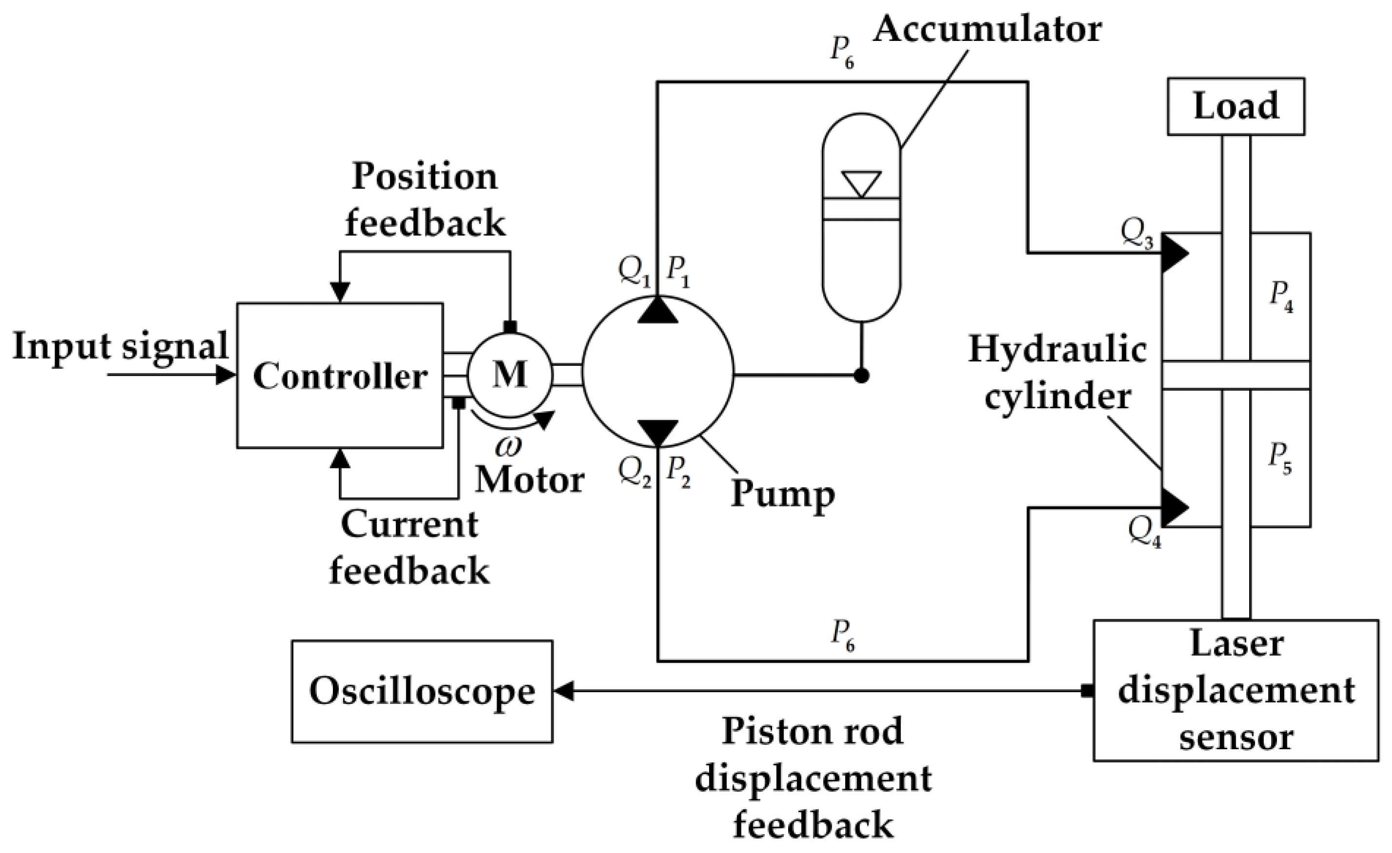
2.2. Components and Working Principle of the Miniature Electro-Hydrostatic Actuator (EHA)

The miniature EHA designed in this paper mainly consists of a brushless DC motor, a micro 2D pump, a hydraulic cylinder, a controller, and a piston accumulator [17]. The main components and their parameters are shown in Table 1, and the physical diagram of each component is shown in Figure 4. The brushless DC motor is used to drive the micro 2D pump forward and in reverse for oil suction and discharge to drive the hydraulic cylinder piston rod movement. The main function of the controller is to drive the motor and protect the hydraulic system. The current of the motor driving the pump increases when the hydraulic system is overloaded, or the pressure is too high. When the current increases to a certain value, the controller controls the motor to maintain maximum current operation to prevent overcurrent burnout, as a way to protect the safety of the hydraulic system. The piston accumulator with a filling pressure of 31.5 MPa and a volume of 0.63 L is connected to the tank of the micro 2D pump by means of a direct connection. Its main function is to prevent oxidation of the oil and compensate for the return of oil to the system. Compared with the traditional EHA system, this miniature EHA removes the check valves, safety valves, and other components with larger volume and mass, further optimizing the structure and reducing the system volume without affecting the overall function of the system [18,19].
The physical diagram of the miniature EHA system is shown in Figure 5. Some hydraulic parameters are indicated in the figure corresponding to Equations (5)–(16) in the later section. And the structural schematic is shown in Figure 6. The simple structure and small size of the EHA designed in this paper can be visualized by comparing it with the size of a dollar coin. The working principle of the miniature EHA system is that, after the input voltage signal from the signal generator, the controller will receive the input signal and feedback signal in accordance with the arithmetic control algorithm, which through the drive amplifier circuit is converted into electrical signals in order to drive the brushless DC motor to drive the micro 2D pump non-stop in forward and reverse rotation. The micro 2D pump outputs a high-pressure fluid to the hydraulic cylinder’s two chambers, and finally pushes the load for work. In practice, for the motor driving the pump to keep turning forward and in reverse, the EHA system continuously sucks and discharges oil, so it has a high working efficiency.

3. Motor Modeling and Control Design

3.1. The Mathematical Model of Brushless DC Motor

The establishment of the mathematical model of the brushless DC motor has important theoretical significance for the control system analysis, and it can be prepared to reflect the motor parameters and phase voltage, phase current, and other data of the function relationship. Generally, we abstract the motor model into a planar two-axis coordinate system. The α β coordinate system is the initial coordinate system, and its coordinate origin coincides with the center point of the motor model. And the d q coordinate system is the coordinate system that follows the rotation of the electronic rotor. After sampling the three-phase currents, the coupled symmetrical three-phase system can be decoupled into a two-phase system that can be controlled independently with the Clark transform to obtain the two-phase currents i α and i β in the d q coordinate system. The Park transformation is then used to generate a time-varying system from the α β coordinate system to the d q coordinate system, thus obtaining the motor’s direct axis current i d and the quadrature axis current i q . The voltage equation for a brushless DC motor in the d q coordinate system is as follows:
u d = R s i d + L d d i d d t ω L q i q
u q = R s i q + L q d i q d t + ω L d i d + ω ψ f
Only a small portion of the electrical power input during motor operation is lost on the copper, and most of the power is used to drive the load. Assuming that the various losses are negligible, then, the electromagnetic power equation of the motor is as follows:
P e = e a i a + e b i b + e c i c
The torque equation is as follows:
T e = 3 2 P e [ ψ f i q + ( L d L q ) i d i q ]
The equation of motion of a brushless DC motor is as follows:
T e T L = J d ω d t + B v ω

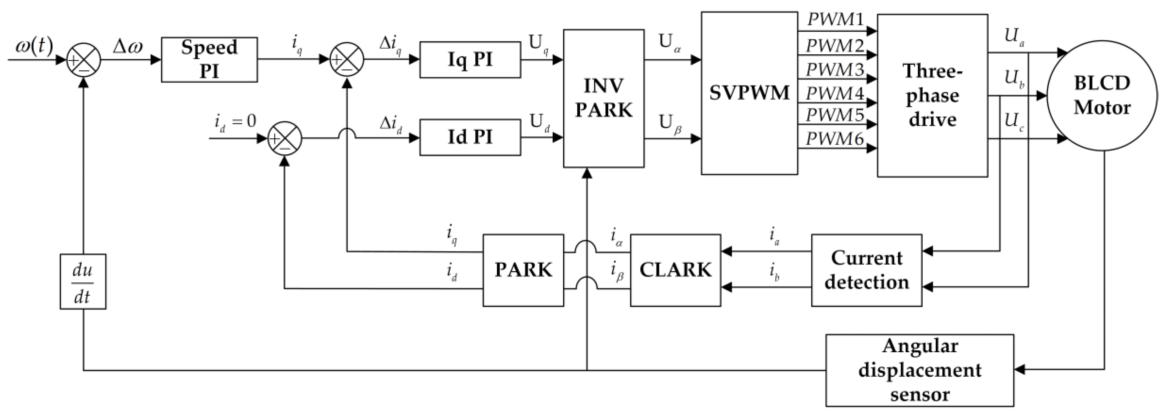
3.2. Control Strategy Design

Although the brushless DC motor used in this paper has the advantages of small size, being lightweight, and having a high torque, in terms of control, the brushless DC motor requires a more complex control technique than the traditional motor. Currently, field-oriented control (FOC) is one of the optimal and most efficient control methods for permanent-magnet synchronous motors and brushless DC motors. The FOC controls the motor’s direct and quadrature axis currents independently of each other to precisely control the motor’s torque.
In order to ensure the maximum output of electromagnetic torque from a brushless DC motor, a control method in which i d = 0 is generally used, so that only the quadrature axis current has an effect on the output torque of the electro-mechanical converter [20]. A control system block diagram of the DC brushless motor is shown in Figure 7, which adopts the double closed-loop algorithm of speed and current. The position of the motor rotor is fed back in real-time through the AS5045 angular displacement sensor on the motor backplane, and the position angle is used for the PI control of FOC and the coordinate transformation calculation. This control algorithm allows the motor to have a stable rotational speed, which reduces the flow pulsation of the system and makes the output of the system more stable and smoother [21,22].

3.3. Simulation Model of the Controller

The simulation model of the EHA motor controller is established in Matlab/Simulink, as shown in Figure 8. The parameters of the motor model are shown in Table 2. In order to make the simulation results more in line with the actual effect, each parameter of the motor model is obtained using experimental measurements with the motor, where the inductance and resistance are measured with the LCR, the flux linkage coefficient is derived from the inverse potential, and the rotational moment of inertia is calculated with 3D modeling.

4. Modelling of The EHA Hydraulic System

4.1. The Mathematical Model of the Pump and the Hydraulic Cylinder

The micro 2D pump designed in this paper is a volumetric pump; according to the principle of moments, the balance of the quantitative pump can be obtained with Equation (6):
M = ( J + J 1 ) d ω d t + K M ω + M 1 + Q ( P 1 P 2 ) 2 π
According to the flow conservation theorem, the actual flow rate of the micro 2D pump is as follows:
Q = d V d t = ω D p
Q 1 = Q α ( P 1 P 2 ) β ( P 1 P 3 )
Q 2 = Q α ( P 1 P 2 ) β ( P 2 P 3 )
Hydraulic cylinders work by generating hydraulic pressure through the pressure difference between the two chambers, thus overcoming the load. The flow continuity equation is as follows:
Q 3 = A p · d x d t + ( V p + A p x ) δ d P 4 d t + β P 4
Q 4 = A p · d x d t + ( V p A p x ) δ d P 5 d t + β P 5
P 1 = P 4 + P 6
P 2 = P 5 P 6
Q 1 = Q 3 ; Q 2 = Q 4
Q 5 = Q 1 + Q 3 2 = Q 2 + Q 4 2
The hydraulic cylinder output force equation is as follows:
F = ( P 5 P 4 ) A p = m d 2 x d t 2 + B d x d t + λ x + F s

4.2. Simulation Modeling of Micro Two-Dimensional (2D) Pump

In this paper, the hydraulic system of the miniature EHA is modeled in AMESim. The components can be selected from the existing component library. Since a 2D pump is essentially a 2D piston that rotates and moves axially at the same time, the pump components in the library are chosen to be replaced with a piston block and a linear rotational modulation transformation as shown in Figure 9. Among them, the transformation of rotational and linear motion reflects the correspondence between the rotation angle of the piston shaft of the micro 2D pump and the displacement of the axial motion. For every 180° rotation of the piston shaft driven by the motor, the piston axial reciprocating motion is carried out once for a complete oil suction and discharge. The correspondence between rotation angle and axial displacement is linear, which reflects the double degree of freedom characteristic of the miniature 2D pump. When the position signal input to the motor angle is sinusoidal, the axial displacement of the pump is also sinusoidal. Then, the output flow rate and the displacement value of the piston rod of the hydraulic cylinder are also sinusoidal. By configuring the sequence of the four variable orifices’ conduction to reflect the micro two-dimensional pump inlet and outlet ports, a spatial 90° distribution is presented. Configuration 1 and configuration 2 have a 90° difference in conduction phase. The transformation of rotational and linear motion and the configuration of the variable orifices is shown in Figure 10.

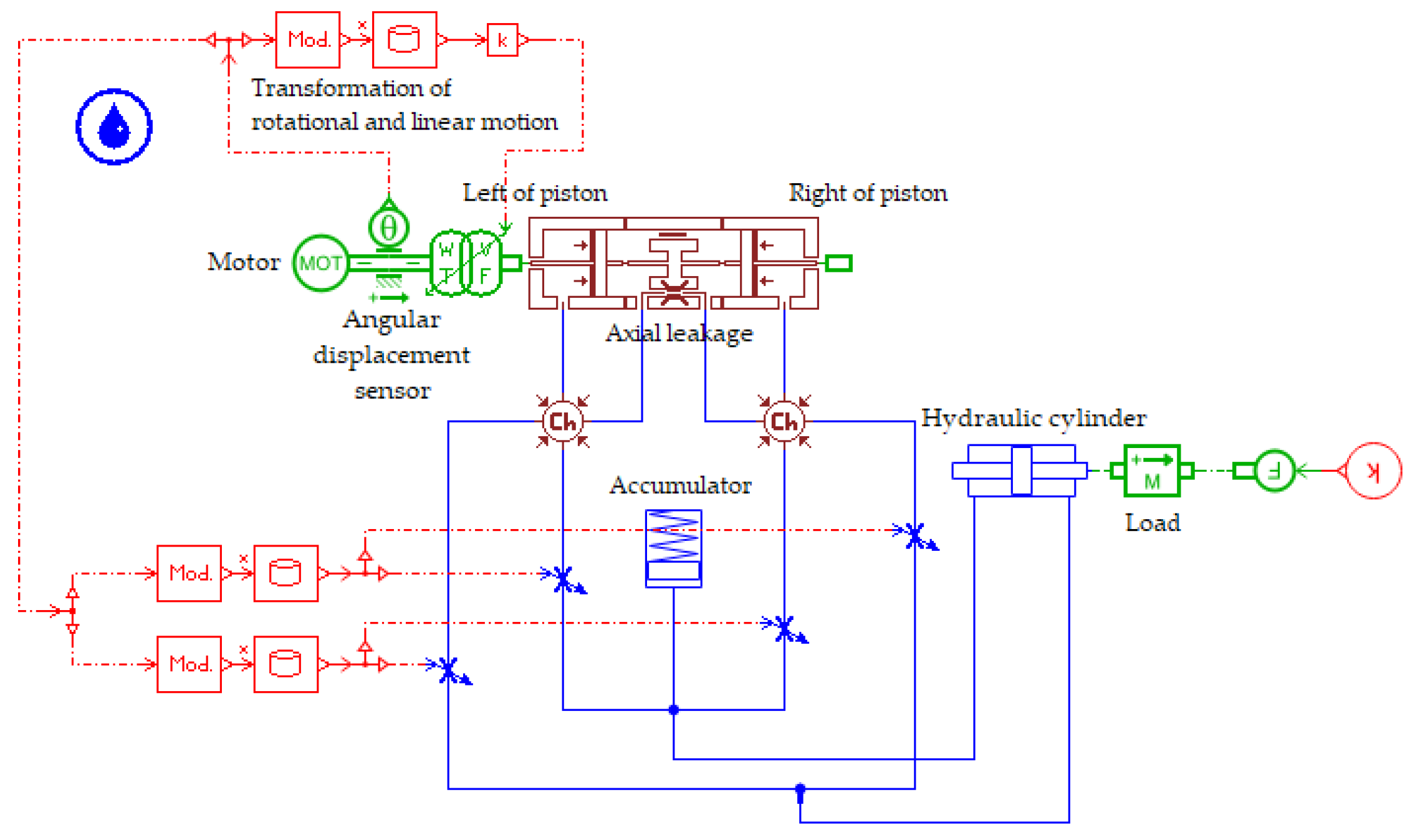
4.3. Simulation Modeling of the Hydraulic System

The EHA hydraulic system modeled in AMESim is shown in Figure 11. In the process of modeling the overall EHA system, the influence of each component on the whole system can be fully considered. The main parameters related to the simulation are shown in Table 3.

5. Simulation and Experimentation

5.1. Simulation

The joint simulation of Simulink and AMESim takes into account the control algorithm and dynamic properties of the motor itself, so it is closer to the actual results. The model for the joint simulation is shown in Figure 12. The result obtained from the control of the motor with the controller model in Simulink is used as an input signal to the EHA system. The actual rotor angle of the motor is fed back to the controller in Simulink through the angular displacement sensor in AMESim, thus realizing the purpose of joint simulation. The purpose of introducing the motor controller for simulation is to speed up the response of the motor rather than the tracking accuracy of the motor speed and position, so the proportional link coefficients of the PI controller can be increased as much as possible to increase the response speed of the motor and thus improve the overall dynamic properties of the miniature EHA system. The parameters of the current loop and the speed loop are shown in Table 4.
Inputting a step signal in Simulink corresponds to the speed step signal of the motor. At different rotational speeds, the time to reach the maximum displacement of the piston rod of the hydraulic cylinder at different rotational speeds is shown in Figure 13. In the joint simulation environment, when a step signal of 6000 r/min is given to the motor, the rise time of this miniature EHA system is 0.158 s.
The frequency response of the EHA system can be obtained by inputting a sinusoidal signal. The maximum displacement of the piston rod of the hydraulic cylinder is 0.62 mm when the input signal is sinusoidal at 0.1 Hz. The displacement amplitude of the piston rod decays as the input signal frequency is gradually increased, as shown in Figure 14. With a sinusoidal signal input at 20 Hz, the maximum displacement of the piston rod is 0.44 mm, and the amplitude is attenuated to −3 dB, which gives a frequency bandwidth of 20 Hz in the simulation environment of the EHA system.

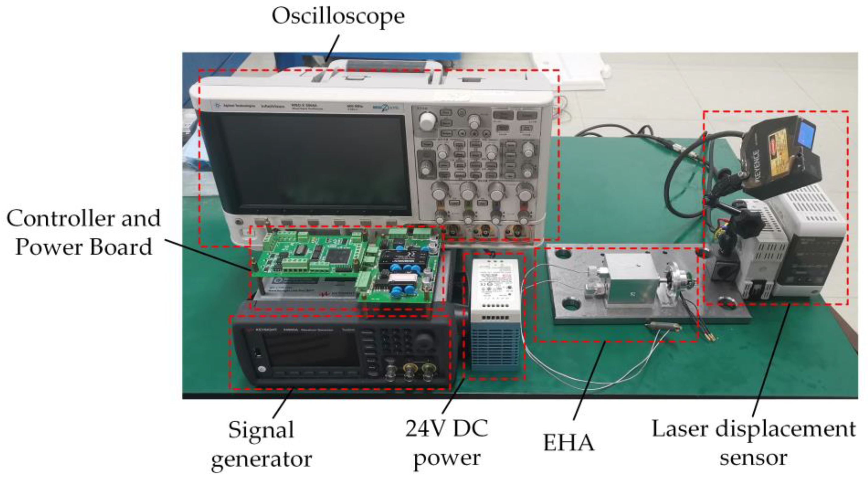
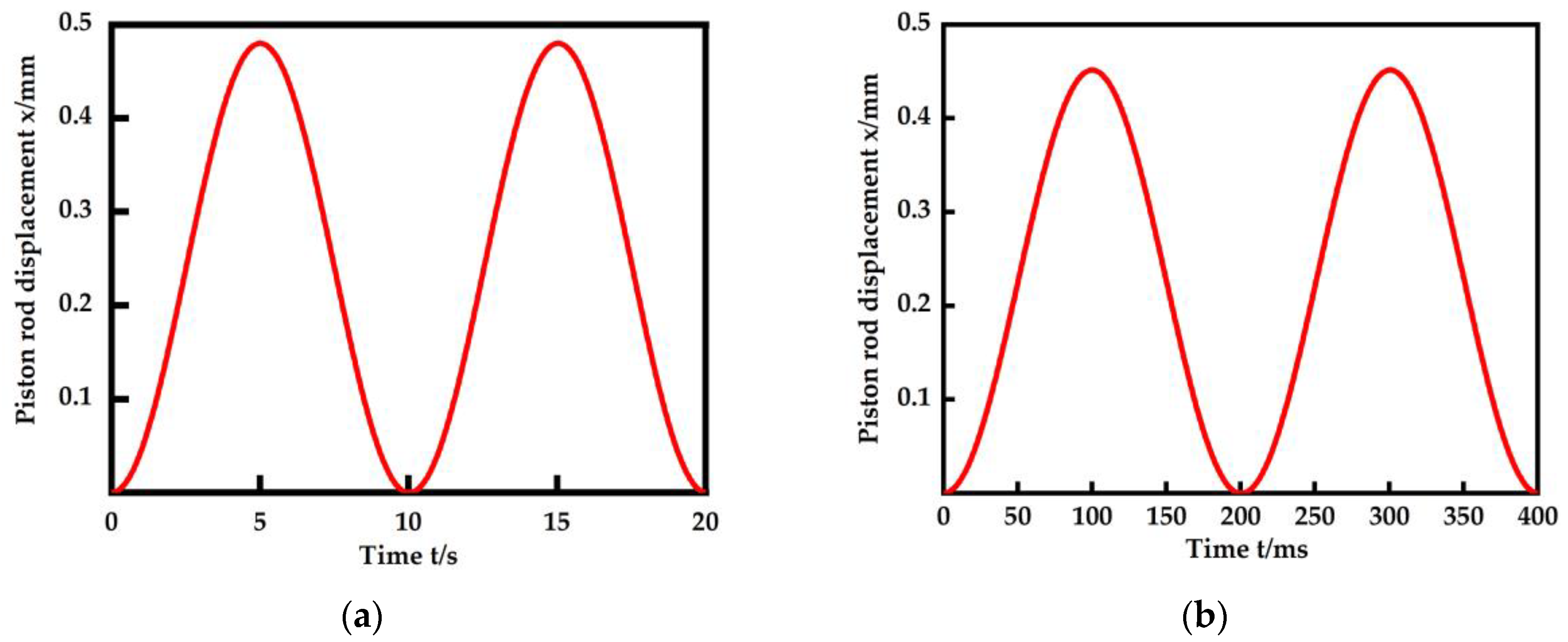
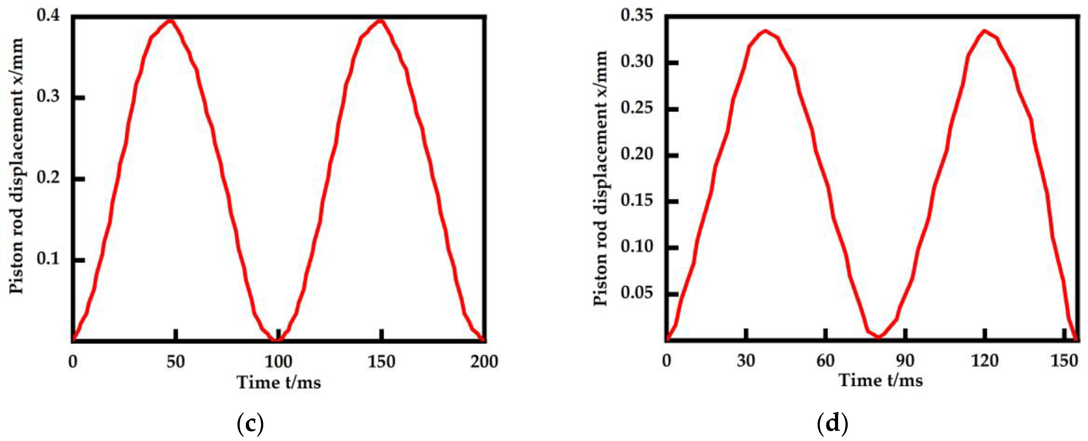
5.2. Experimental Research

The dynamic properties of the motor for the experiment were first tested. The micro 2D pump requires a constant 180° forward and reverse rotation. The forward rotation is used to supply the pressurized fluid, while the reverse rotation is used to recover the pressurized fluid and avoid backflow in the hydraulic lines. When the micro 2D pump is activated, the forward rotation system provides the high-pressure fluid to drive the power actuator, while the reverse rotation system recovers this pressurized fluid and prevents it from flowing back into the hydraulic lines through the reverse rotation function. If the micro 2D pump does not have a forward and reverse function, then at the end of the work of the hydraulic mechanism, the pressurized fluid in the hydraulic line will flow back into the hydraulic pump, causing damage to the miniature pump. As a result, the dynamic properties of the DC brushless motor are investigated under the conditions of 180° forward and reverse rotation. Figure 15 shows the speed step response of this motor and Figure 16 shows the frequency response of this motor. In a no load situation, the motor has a rise time of 19 ms and an overshoot of 17.8% at a speed step input of 2000 r/min with almost no steady state error. On the other hand, the frequency bandwidth of the motor is about 17 Hz, and it can be seen that the amplitude–frequency decay is faster than the phase decay due to the phase compensation technique used in the control algorithm. So, later on, when studying the frequency properties of the EHA, the frequency at which its amplitude decays at −3 dB is taken as the frequency bandwidth.
An experimental stand was built based on the miniature EHA prototype, which is mainly composed of the EHA system, controller, power supply, computer, oscilloscope, etc., as shown in Figure 17.
The experimentally obtained step response and frequency response of the miniature EHA are shown in Figure 18 and Figure 19, respectively.
For the step response, the rise times of the EHA system were 0.591 s, 0.374 s, and 0.242 s for different speed settings of the DC brushless motor. After a step in the input signal at 0.1 s, the piston rod will first have a short period of slow advance, due to the small amount of air still present in the system. The period of slow movement becomes shorter as the given value of speed increases, after which the piston rod is displaced at a faster speed.
For the frequency response, at a 0.1 Hz input, the hydraulic cylinder piston rod displacement output curve is very smooth, with an amplitude of 0.47 mm. When the input signal frequency is increased to 5 Hz, the output displacement remains stable, and the amplitude does not decay much. At an input signal of 10 Hz, it is clear that the displacement curve is no longer smooth and fluctuates due to the increase in speed. And the amplitude decay also becomes obvious. As the input signal is gradually increased to 13 Hz, the amplitude of the piston rod displacement decreases to −3 dB and the fluctuations in the waveform due to flow instability become more pronounced. In summary, the experiments yielded a frequency bandwidth of about 13 Hz for this EHA.

6. Conclusions and Future Work

In this paper, a miniature EHA system is designed to be studied with a micro 2D pump and a miniature brushless DC motor as the core. The following conclusions were obtained:
  • An analysis of the structure and working principle of the micro 2D pump and the EHA system was performed. Compared with previous EHAs, the miniature EHA designed in this paper is smaller in size and simpler in structure. The total weight of this EHA does not exceed 300 g.
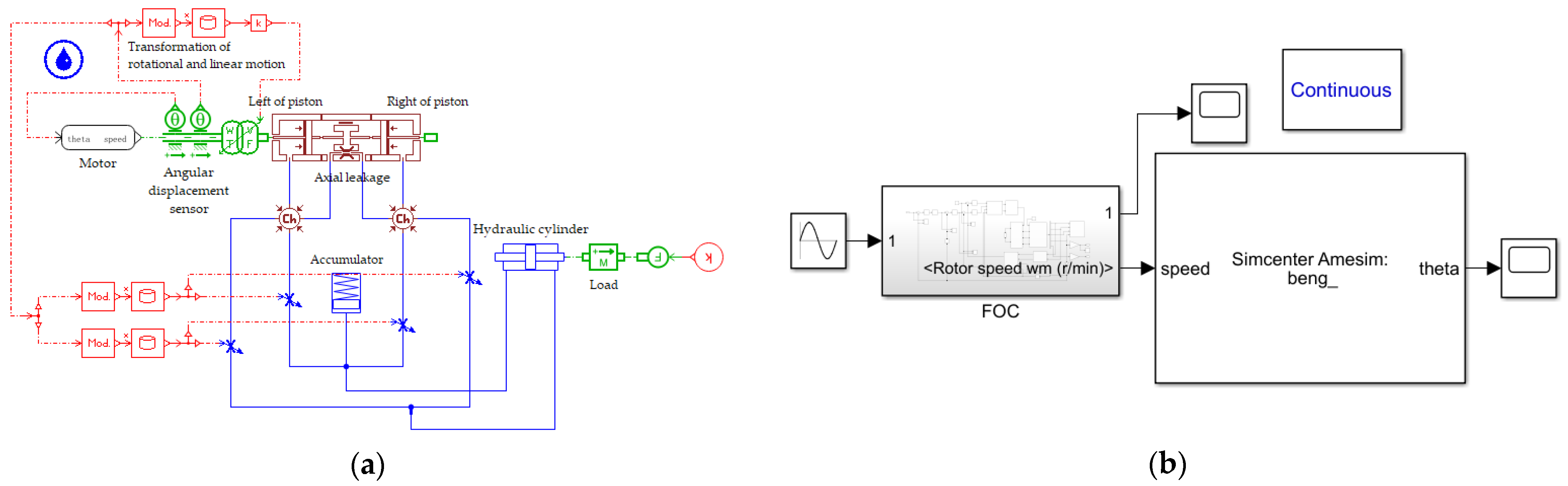
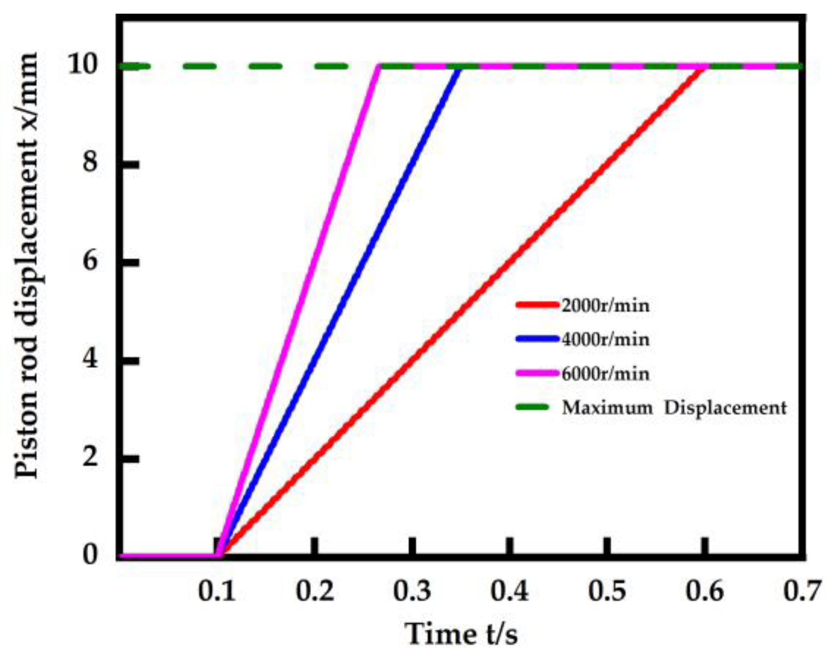
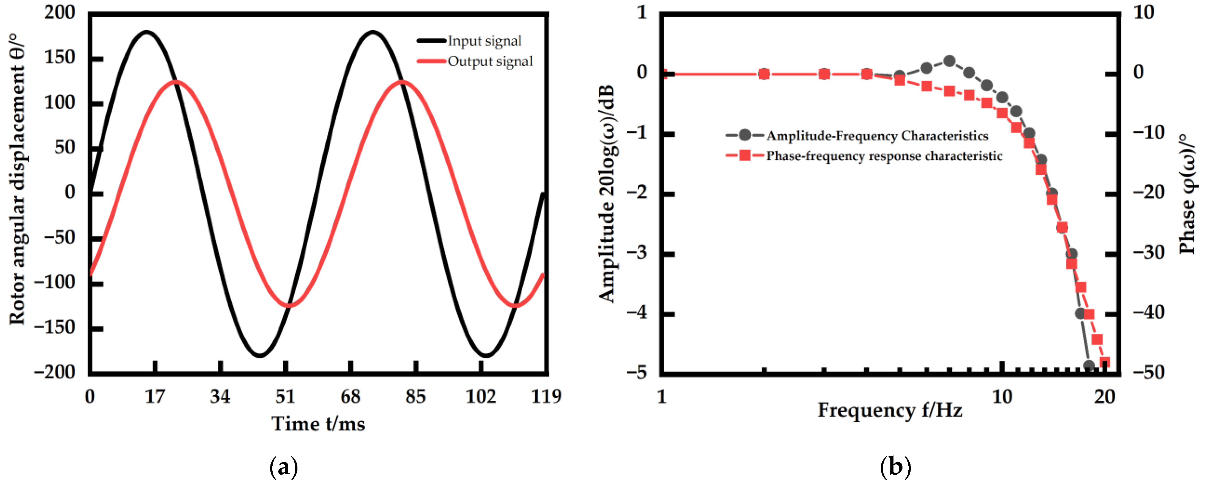
  • A simulation model of the miniature EHA system was developed, and it was controlled using a suitable control algorithm. A joint simulation of Simulink and AMESim was used, and the simulation data show that the rise time of this EHA system is 0.158 s with a step signal of 6000 r/min and a bandwidth of 20 Hz.
  • An experimental verification of the results of theoretical studies was carried out on a specially designed experimental stand for studying the dynamic properties of the EHA system. The rise time of the miniature EHA at a step signal of 6000 r/min is 0.242 s and the bandwidth is 13 Hz. The experimental results can correspond to the simulation results, indicating the reliability of this EHA system design scheme.
Our work shows that the solution of the miniature EHA system is reasonable, and it has very awesome dynamic properties. The miniature EHA designed in this paper is not only small in size and simple in structure, but also has good dynamic properties, which are expected to be used in wearable exoskeleton equipment [25,26].
Similarly, the miniature EHA has a lot of work that can be performed to improve it in the future. Although the EHA designed in this paper adopts a smaller and better-performance pump and motor, it is still a split design. And it can be designed as a one-piece EHA with higher integration in the future.

Author Contributions

Conceptualization, Y.A. and J.R.; methodology, C.T. and J.R.; software, Y.A.; validation, J.M. and X.Z.; formal analysis, Y.A.; investigation, Y.A. and J.M.; resources, Y.A. and X.Z.; data curation, Y.A.; writing—original draft preparation, Y.A.; writing—review and editing, Y.A.; visualization, Y.A.; supervision, S.L.; project administration, Y.A.; funding acquisition, S.L. All authors have read and agreed to the published version of the manuscript.

Funding

This research received no external funding.

Data Availability Statement

Data are contained within the article.

Conflicts of Interest

The authors declare no conflicts of interest.

Abbreviations

ParameterValue
R s Internal resistance of motor
L q Quadrature axis inductance
L d Direct axis inductance
ω Motor speed
ψ f Flux linkage coefficient
i a , i b , i c Stator phase winding current
e a , e b , e c Stator phase winding electromotive force
J Rotor moment of inertia
T L Load torque
Q Total pump displacement
J 1 Pump moment of inertia
K M Friction coefficient
M 1 Loss torque
P 1 Pump discharge pressure
P 2 Pump inlet pressure
V Pump volume change
D p Pump displacement
Q 1 Pump input flow
Q 2 Pump output flow
α Internal leakage coefficient
β External leakage coefficient
P 3 Pump external leakage port pressure
V p Volume of the fluid
A p Effective area of the piston of the hydraulic cylinder
x Displacement of the piston rod of the hydraulic cylinder
δ Modulus of elasticity of the volume of the fluid
P 4 , P 5 Pressure of the two chambers of the hydraulic cylinder
Q 3 , Q 4 Flow rate of the two chambers of the hydraulic cylinder
Q 5 Flow rate of the load of the hydraulic cylinder
P 6 Pressure drop in the hydraulic line of the EHA
m Mass of the piston rod of the hydraulic cylinder
λ Elastic stiffness of the load
B Piston damping coefficient
F s External resistance

References

  1. Li, B.; Liu, Y.; Tan, C.; Qin, Q.; Lu, Y. Review on electro-hydrostatic actuator: System configurations, design methods and control technologies. Int. J. Mechatron. Manuf. Syst. 2020, 13, 323–346. [Google Scholar] [CrossRef]
  2. Gaile, A.; Lue, Y. Electro-hydraulic Actuation (EHA) Systems for Primary Flight Control, Landing Gear and Other Type of Actuation. In Proceedings of the 2016 IEEE International Conference on Aircraft Utility Systems (AUS), Beijing, China, 10–12 October 2016; IEEE: New York, NY, USA, 2016; pp. 723–728. [Google Scholar]
  3. Todeschi, M. Airbus-EMAs for flight controls actuation system 2012 status and perspectives. In Proceedings of the 5th International Conference on Recent Advances in Aerospace Actuation Systems and Components, Toulouse, France, 13–14 June 2012; pp. 1–10. [Google Scholar]
  4. Fu, Y.; Han, X.; Yang, R. A review of design methods for electro-hydrostatic actuators. J. Beijing Univ. Aeronaut. Astronaut. 2017, 43, 1939–1952. [Google Scholar] [CrossRef]
  5. Zhu, T.; Xie, H.; Yang, H. Design and tracking control of an electro-hydrostatic actuator for a disc cutter replacement manipulator. Autom. Constr. 2022, 142, 104480. [Google Scholar] [CrossRef]
  6. Liu, Z.; Lei, X.; Li, L. Research on the effect of servo motor response speed on the performance of EHA position control. Hydraul. Pneum. Seal. 2022, 42, 41–46. [Google Scholar] [CrossRef]
  7. Nakanishi, T.; Komagata, M.; Yamamoto, K.; Nakamura, Y. Toward High Power-to-Weight Ratio Electro-hydrostatic Actuators for Robots. In Springer Proceedings in Advanced Robotics; Springer Science and Business Media B.V.: Berlin/Heidelberg, Germany, 2021; Volume 19, pp. 116–125. [Google Scholar] [CrossRef]
  8. Niu, Z.; Liu, Y.S.; Wang, L.; Yang, S.; Li, X. Portable electro-hydraulic actuator technology based on spherical micro pump. In Proceedings of the 2016 IEEE International Conference on Aircraft Utility Systems (AUS), Beijing, China, 10–12 October 2016; pp. 114–118. [Google Scholar] [CrossRef]
  9. Aubin, C.A.; Choudhury, S.; Jerch, R.; Archer, L.A.; Pikul, J.H.; Shepherd, R.F. Electrolytic vascular systems for energy-dense robots. Nature 2019, 571, 51–57. [Google Scholar] [CrossRef] [PubMed]
  10. Song, X.; Li, H.Y.; Li, Y.; Luo, X. The development of a high-speed miniature pump with dynamic bearing. J. Phys. Conf. Ser. 2022, 2217, 012049. [Google Scholar] [CrossRef]
  11. Huang, Y.; Ruan, J.; Chen, Y.; Ding, C.; Li, S. Research on the volumetric efficiency of 2D piston pumps with a balanced force. Energies 2020, 13, 4796. [Google Scholar] [CrossRef]
  12. Jin, D.; Ruan, J.; Li, S.; Meng, B.; Wang, L. Modelling and validation of a roller-cam rail mechanism used in a 2D piston pump. J. Zhejiang Univ. Sci. A 2019, 20, 201–217. [Google Scholar] [CrossRef]
  13. Zhong, Q.; Xu, E.G.; Jia, T.W.; Yang, H.Y.; Zhang, B.; Li, Y.B. Dynamic performance and control accuracy of a novel proportional valve with a switching technology-controlled pilot stage. J. Zhejiang Univ.-Sci. A 2022, 23, 272–285. [Google Scholar] [CrossRef]
  14. Lu, L.; Chen, Y.; Tong, C.; Ruan, J.; Li, S. Design strategy and performance evaluation of novel miniature two-dimensional (2D) piston pump with a dual stacking mechanism. Alex. Eng. J. 2023, 62, 541–554. [Google Scholar] [CrossRef]
  15. Chao, Q.; Xu, Z.; Tao, J.; Liu, C. Capped piston: A promising design to reduce compressibility effects, pressure ripple and cavitation for high-speed and high-pressure axial piston pumps. Alex. Eng. J. 2023, 62, 509–521. [Google Scholar] [CrossRef]
  16. Zielinski, M.; Myszkowski, A.; Pelic, M.; Staniek, R. Low-speed radial piston pump as an effective alternative power transmission for small hydropower plants. Renew. Energy 2022, 182, 1012–1027. [Google Scholar] [CrossRef]
  17. Wang, F.; Wu, J.; Lin, Z.; Zhang, H.; Xu, B. A power-sharing electro-hydraulic actuator system to downsize electric motors for electric mobile machines. Energy 2023, 284, 129343. [Google Scholar] [CrossRef]
  18. Komagata, M.; Yamamoto, K.; Nakamura, Y. Compact, backdrivable, and efficient design of linear electro-hydrostatic actuator module. Adv. Robot. 2022, 36, 1030–1047. [Google Scholar] [CrossRef]
  19. Shkolnikov, V.; Ramunas, J.; Santiago, J.G. A self-priming, roller-free, miniature, peristaltic pump operable with a single, reciprocating actuator. Sens. Actuators A Phys. 2010, 160, 141–146. [Google Scholar] [CrossRef] [PubMed]
  20. Hadla, H.; Santos, F. Performance Comparison of Field-oriented Control, Direct Torque Control, and Model-predictive Control for SynRMs. Chin. J. Electr. Eng. 2022, 8, 24–37. [Google Scholar] [CrossRef]
  21. Dörr, M.; Leitenberger, F.; Wolter, K.; Matthiesen, S.; Gwosch, T. Model-Based Control Design of an EHA Position Control Based on Multicriteria Optimization. Machines 2022, 10, 1190. [Google Scholar] [CrossRef]
  22. Liu, J.; Huang, Y.; Helian, B.; Nie, Y.; Chen, Z. Flow match and precision motion control of asymmetric electro-hydrostatic actuators with complex external force in four-quadrants. J. Frankl. Inst. 2023, 361, 1025–1039. [Google Scholar] [CrossRef]
  23. Banaszek, A.; Dašić, P.; Turmanidze, E. The influence of tilt angle of the inclined plate on the gradient of the pressure increase in the piston axial pump cylinder. In Proceedings of the Fluid Power International Conference, Maribor, Slovenia, 21 September 2023. [Google Scholar] [CrossRef]
  24. Petrović, R.; Banaszek, A.; Andjelković, M.; Qananah, H.R.; Alnagasa, K.A. Experimental Tests of the Piston Axial Pump with Constant Pressure and Variable Flow. Designs 2024, 8, 5. [Google Scholar] [CrossRef]
  25. Zhao, H.; Zhou, J.; Ma, S.; Du, S.; Liu, H.; Han, L. Design and Experiments of Electro-Hydrostatic Actuator for Wheel-Legged Robot with Fast Force Control Response. Machines 2023, 11, 685. [Google Scholar] [CrossRef]
  26. Kumar, M. A survey on electro hydrostatic actuator: Architecture and way ahead. Mater. Today Proc. 2021, 45 Pt 7, 6057–6063. [Google Scholar] [CrossRef]
Figure 1. Enlarged view of a micro two-dimensional (2D) pump.
Machines 12 00114 g001
Figure 2. Micro two-dimensional (2D) pump body three-dimensional structure drawing.
Machines 12 00114 g002
Figure 3. Micro two-dimensional (2D) pump working principle diagram. (a) pump in suction condition; (b) pump in oil drained condition.
Machines 12 00114 g003
Figure 4. The physical diagram of main components. (a) brushless DC motor; (b) 2D pump; (c) hydraulic cylinder.
Machines 12 00114 g004
Figure 5. The physical diagram of the miniature EHA system. (a) top view; (b) main view.
Machines 12 00114 g005
Figure 6. Schematic diagram of the structure of the EHA system.
Machines 12 00114 g006
Figure 7. The control algorithm of the brushless DC motor in EHA.
Machines 12 00114 g007
Figure 8. Controller simulation model in Simulink.
Machines 12 00114 g008
Figure 9. AMESim modeling of the micro two-dimensional (2D) pump.
Machines 12 00114 g009
Figure 10. The transformation of rotational and linear motion and the configuration of the variable orifices for the micro two-dimensional (2D) pump.
Machines 12 00114 g010
Figure 11. AMESim modeling of the EHA system.
Machines 12 00114 g011
Figure 12. Modeling of the joint simulation. (a) the model in AMESim; (b) the model in Simulink.
Machines 12 00114 g012
Figure 13. Step response in the joint simulation.
Machines 12 00114 g013
Figure 14. Frequency response in the joint simulation. (a) 0.1 Hz; (b) 5 Hz; (c) 10 Hz; (d) 20 Hz.
Machines 12 00114 g014
Figure 15. Experiments on step response of the DC brushless motor speed.
Machines 12 00114 g015
Figure 16. Experiments on frequency response of the DC brushless motor. (a) frequency response at 17 Hz; (b) frequency properties of the motor.
Machines 12 00114 g016
Figure 17. The experimental stand of the miniature EHA.
Machines 12 00114 g017
Figure 18. Step response experiments on the miniature EHA.
Machines 12 00114 g018
Figure 19. Frequency response experiments of the miniature EHA. (a) 0.1 Hz; (b) 5 Hz; (c) 10 Hz; (d) 13 Hz.
Machines 12 00114 g019aMachines 12 00114 g019b
Table 1. The parameters of main components.
Component NameTypesWeight/gBasic Size/mm
MotorD18062026 × 18
PumpTwo-dimensional piston pumps51.537 × 21
Hydraulic cylinderDouble rod hydraulic cylinder49.639 × 10
Table 2. Brushless DC motor parameters.
ParametersValueUnit
Resistance0.1139Ω
Quadrature axis inductance L d 8.24μH
Direct axis inductance L q 13.35μH
Flux linkage coefficient ψ f 0.00407Wb
Rotor moment of inertia5.64g·cm2
Pole pairs7none
Table 3. Parameters related to the EHA system [23,24].
ParametersValueUnit
Oil density850kg/m3
Volumetric modulus of oil700MPa
Displacement of the pump0.0035mL/r
Pump RPMMax 15,000r/min
Volumetric efficiency of the pump90%none
Piston rod displacement±10mm
Weight of the load0.5kg
Basic pressure10MPa
Pump moment of inertia62.3g·mm2
Effective area of the piston of the hydraulic cylinder12.567mm2
Mass of the piston rod of the hydraulic cylinder21.2g
Piston damping coefficient0.25none
Table 4. Closed-loop parameters of the Simulink controller.
ParametersValue
I d Current K p 21
I d Current K i 284.75
I q Current K p 33
I q Current K i 284.75
Speed K p 4.5
Speed K i 7
Disclaimer/Publisher’s Note: The statements, opinions and data contained in all publications are solely those of the individual author(s) and contributor(s) and not of MDPI and/or the editor(s). MDPI and/or the editor(s) disclaim responsibility for any injury to people or property resulting from any ideas, methods, instructions or products referred to in the content.

