Guiding the Selection of Multi-Vector Model Predictive Control Techniques for Multiphase Drives

 ,
,  ,
,  ,
,  and
and
Abstract
:1. Introduction
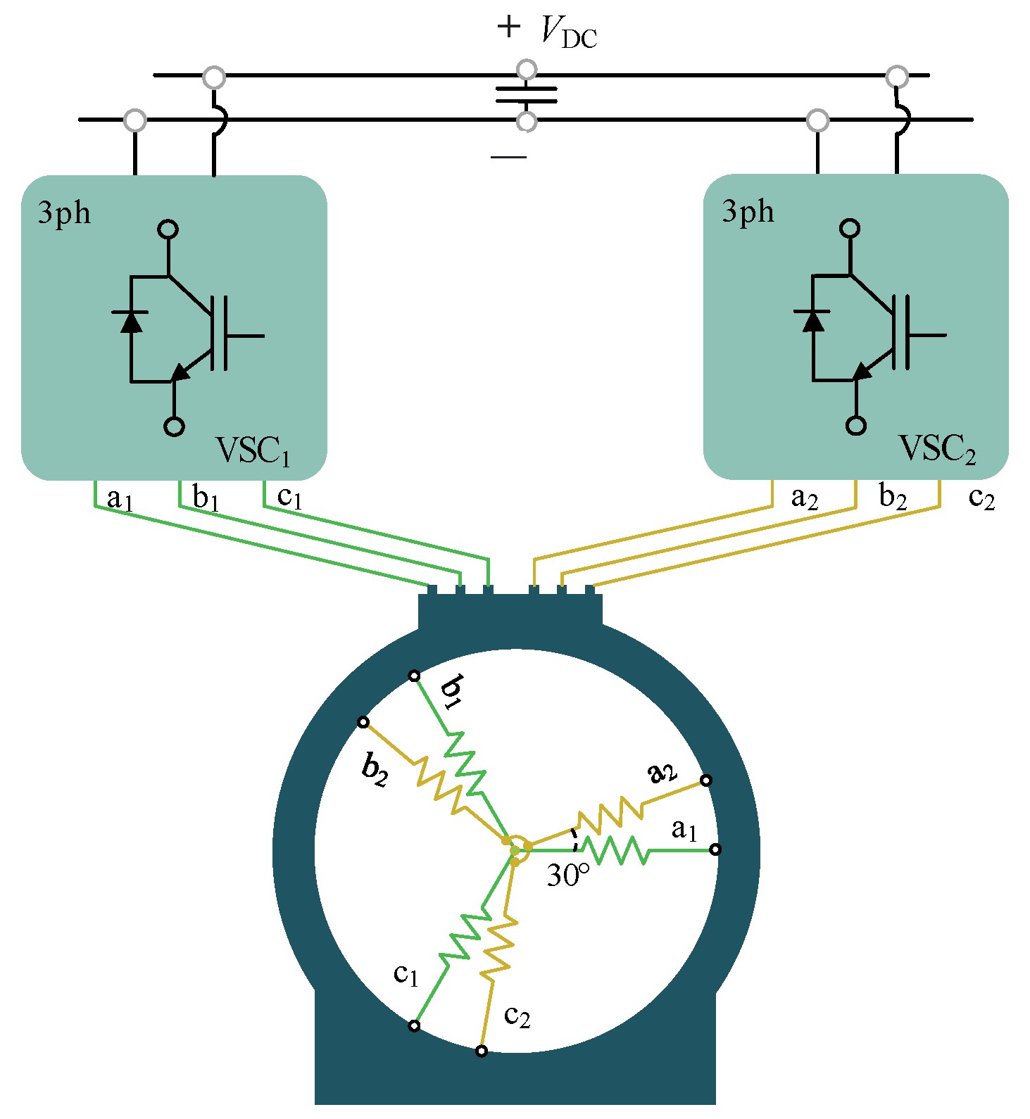
2. Six-Phase Electric Drives: Generalities and Topology
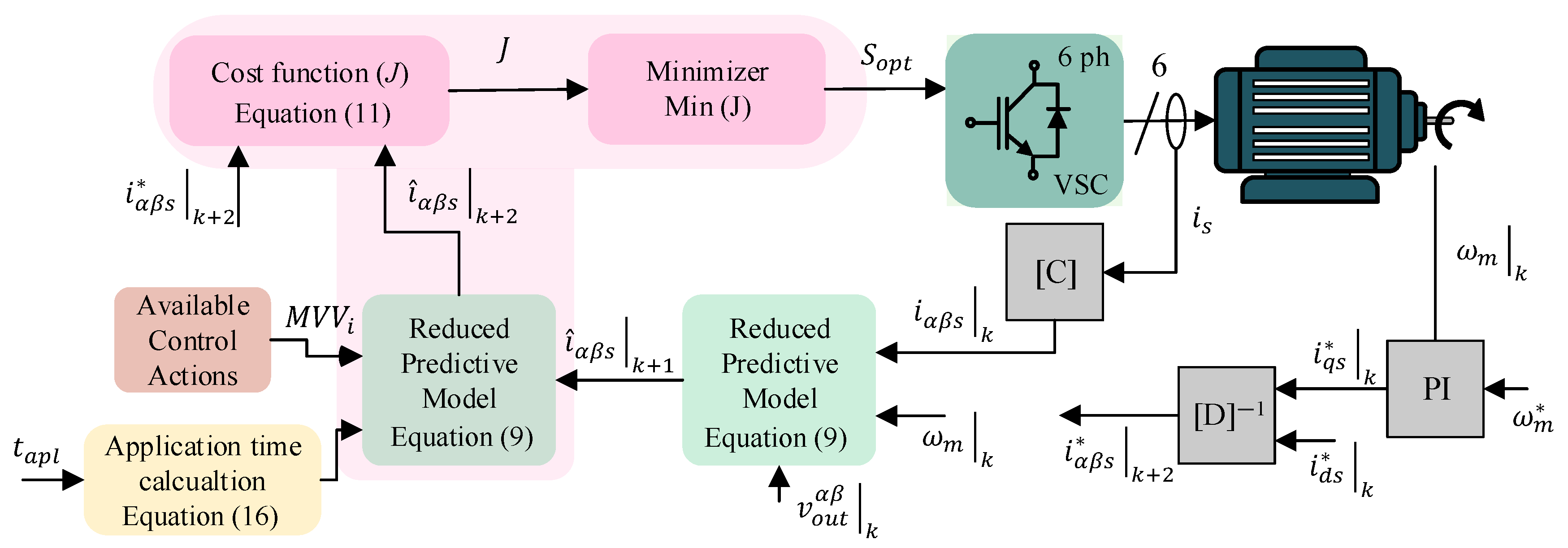
3. Multi-Vector MPC-Based Schemes Assessed
3.1. FCS-MPC
3.2. VV-MPC
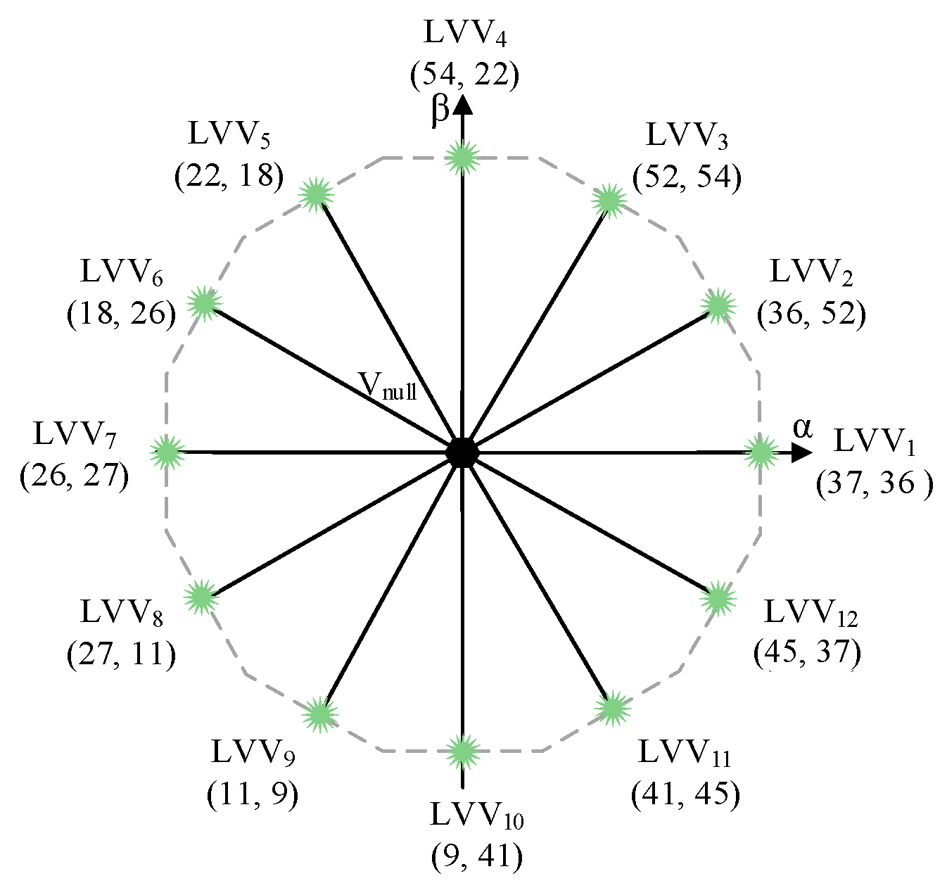
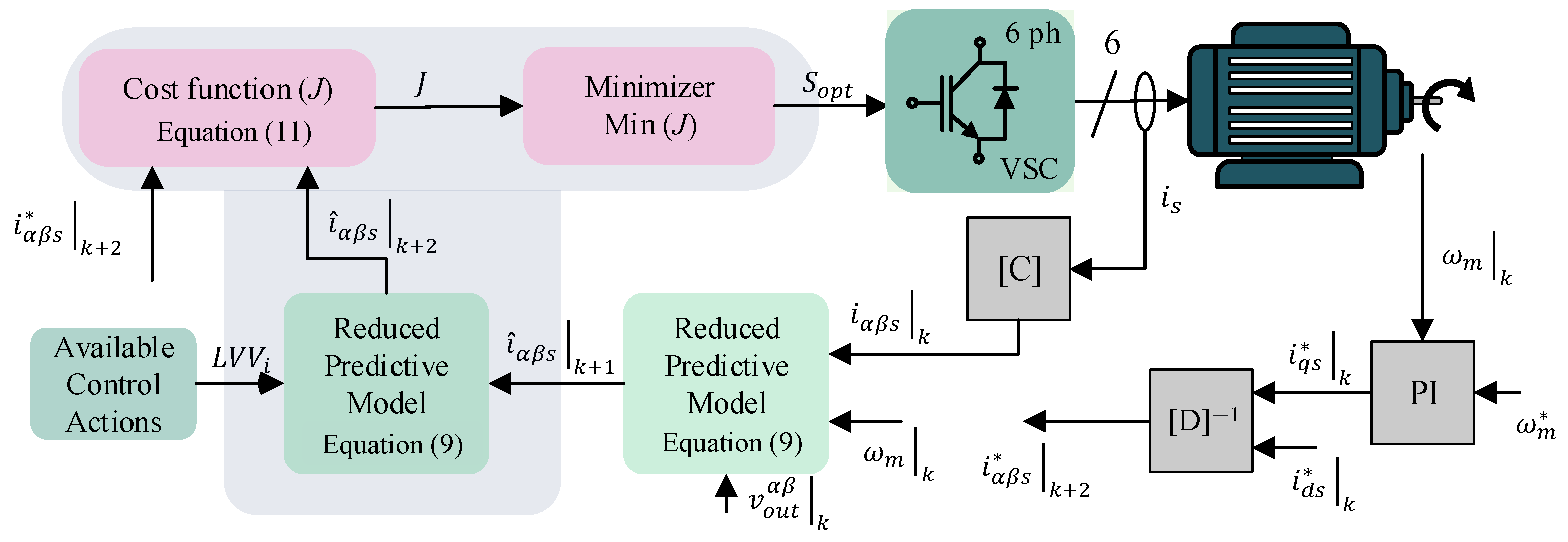
3.3. LVV-MPC
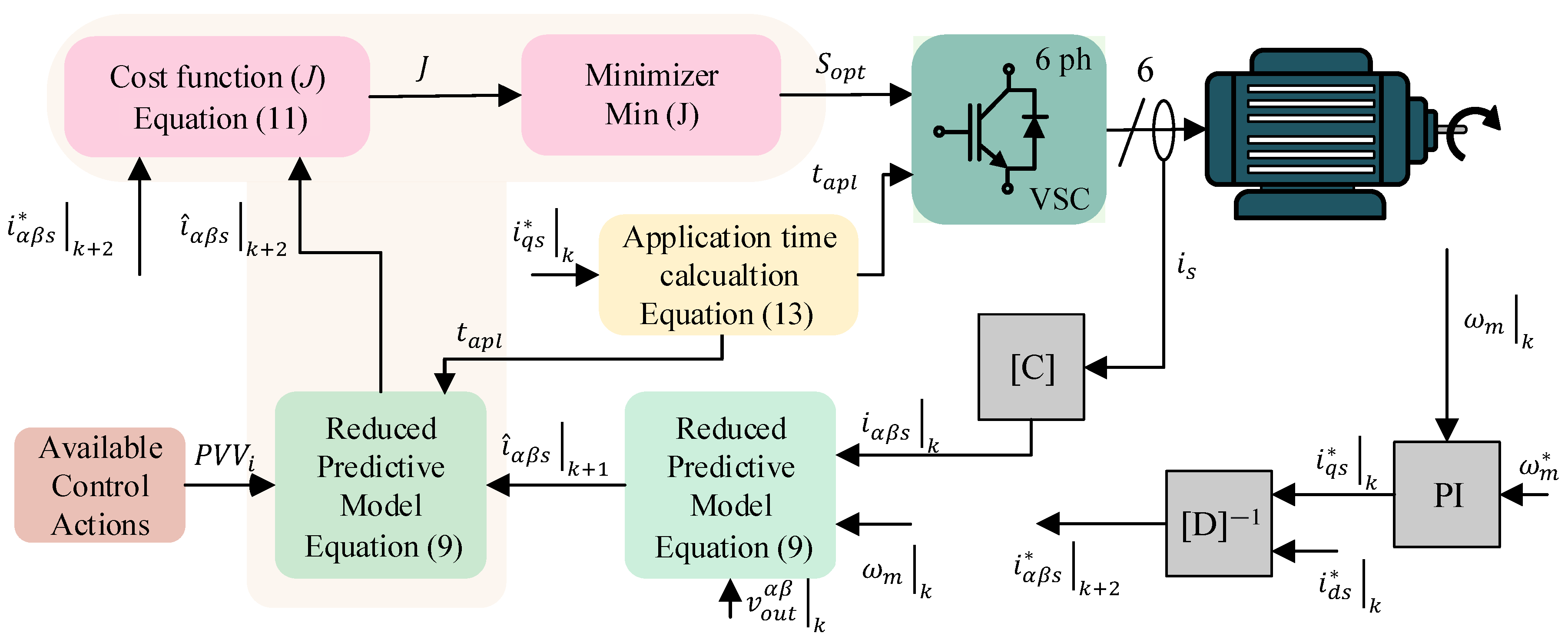
3.4. PULLA-MPC
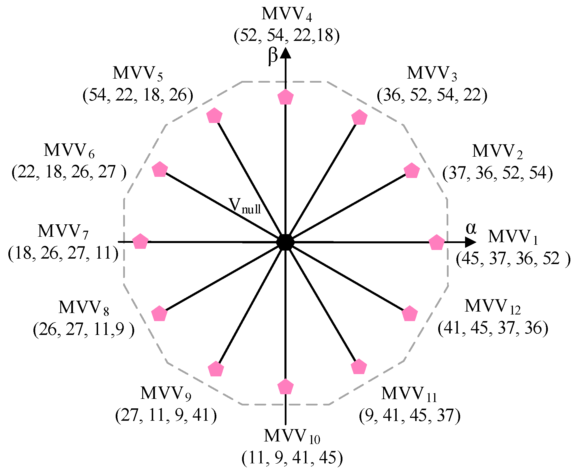
3.5. MV5-MPC
4. Influencing Factors Used to Select an Adequate Multi-Vector MPC Scheme
- High current quality.
- Suitable current tracking.
- Minimal power losses.
- IF1.
- IF2.
- IF3.
- IF4.
- IF5.
4.1. Current Quality in Multiphase Electric Drives
4.2. Current Tracking Performance
4.3. Minimal Power Losses
5. Experimental Validation
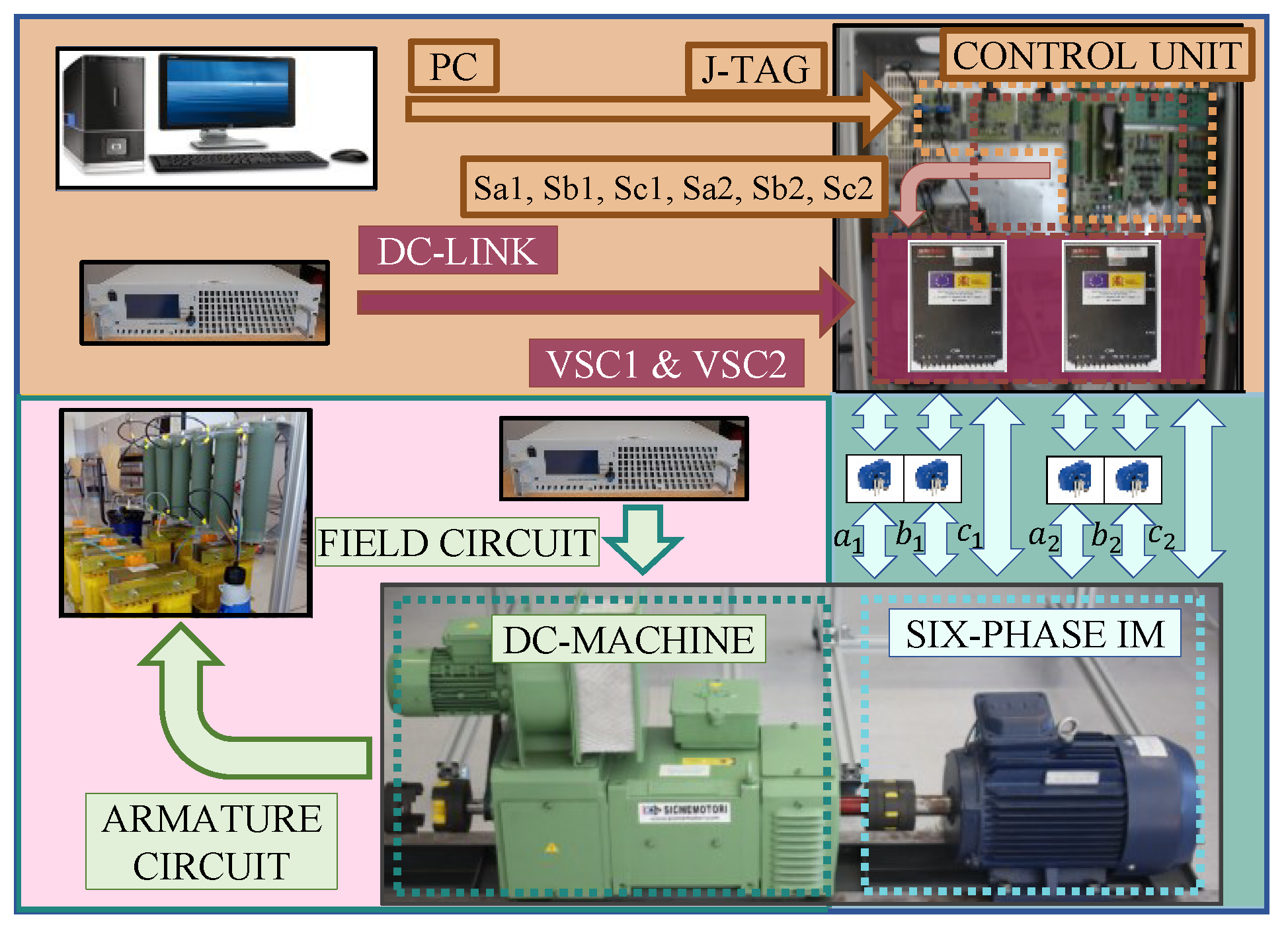
5.1. Experimental Setup
5.2. Experimental Results
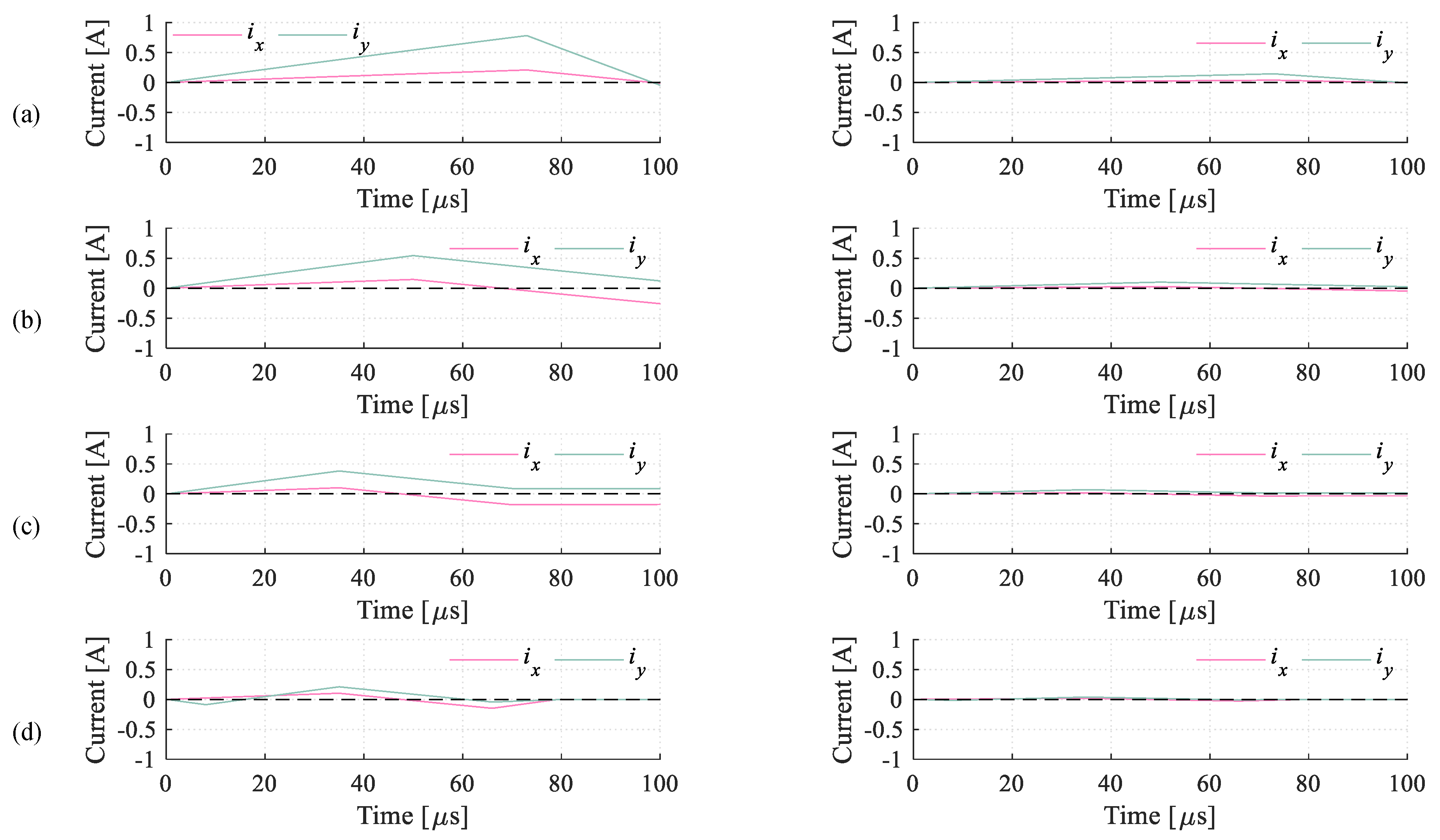
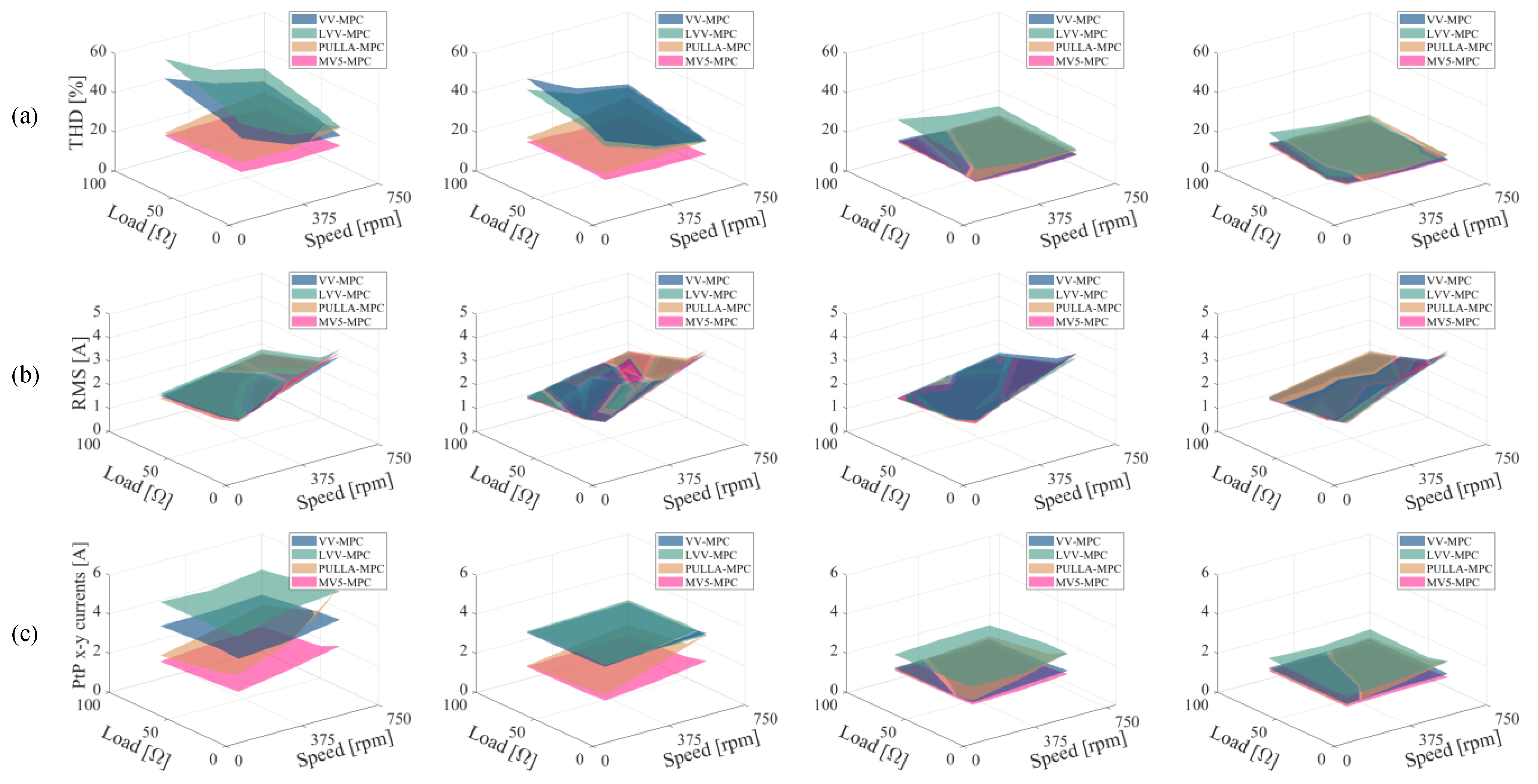
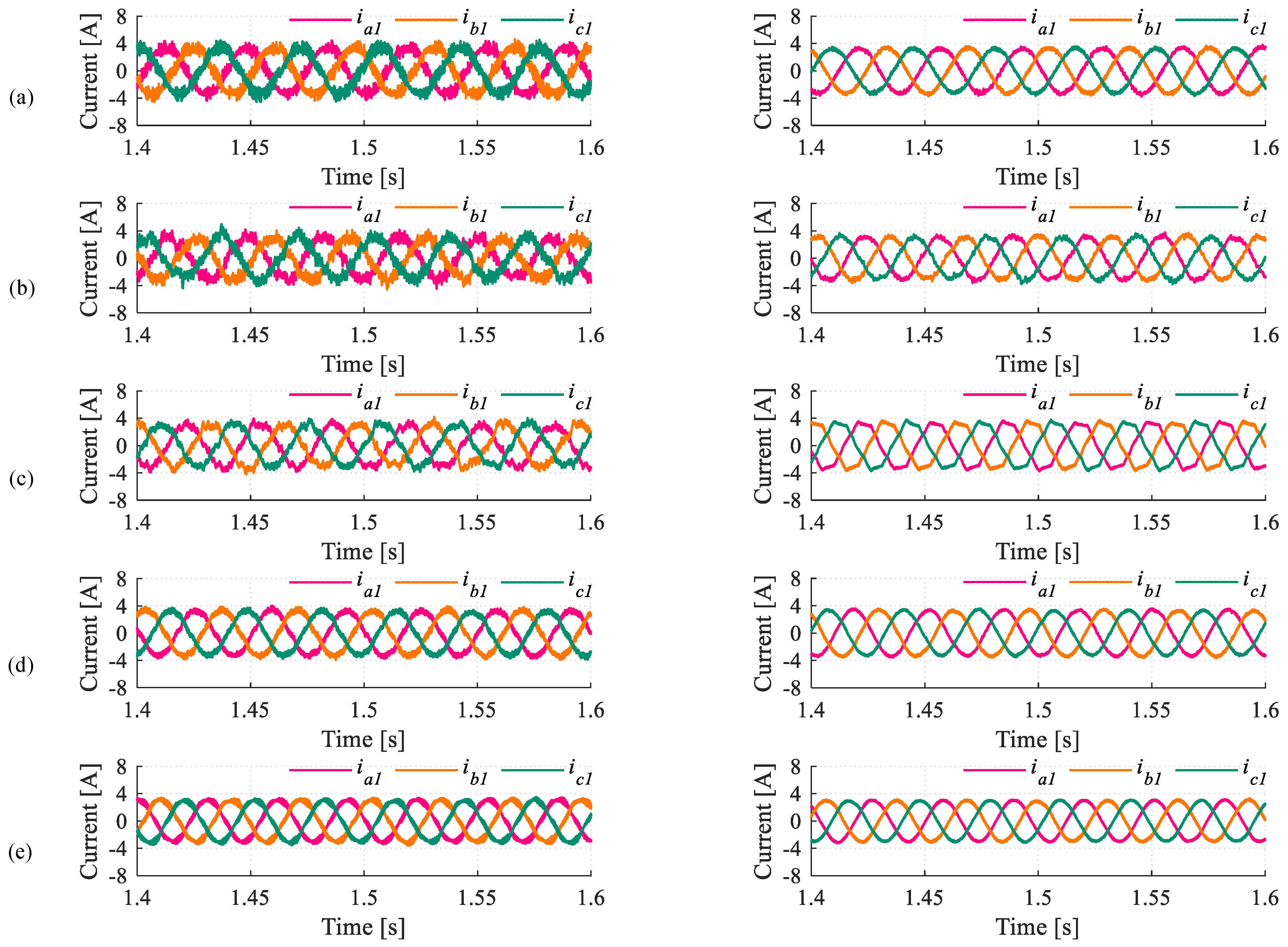
5.2.1. Current Quality Analysis
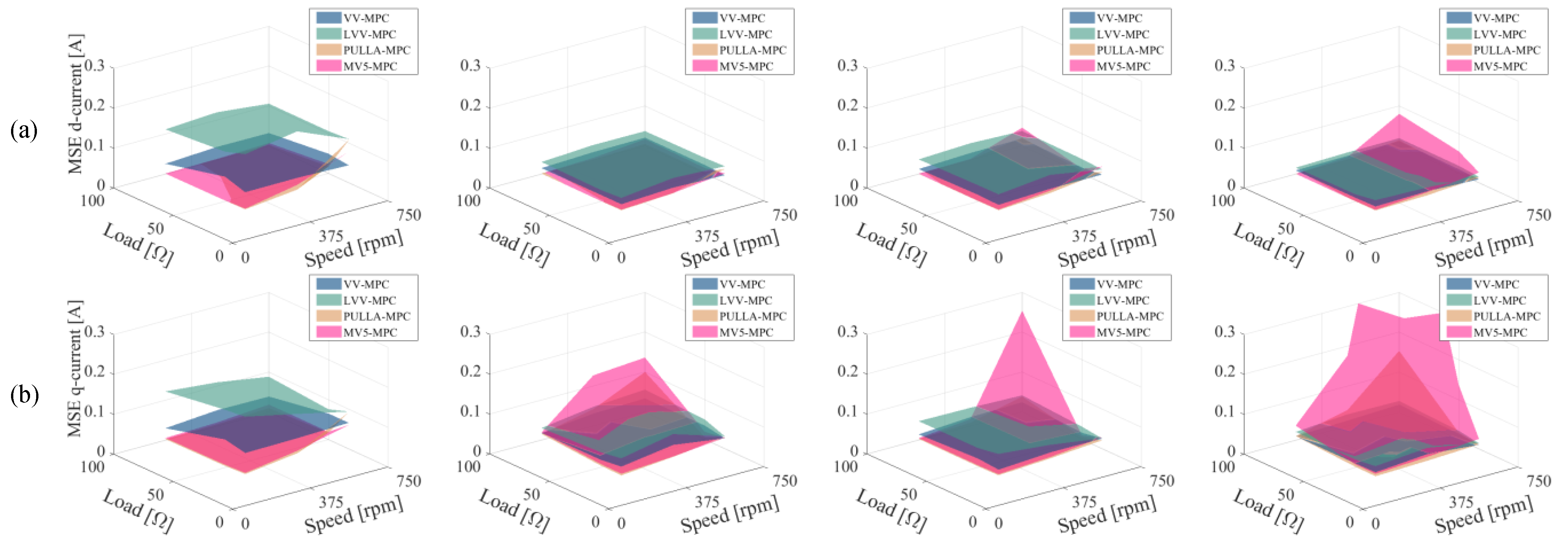
5.2.2. Current Tracking Performance
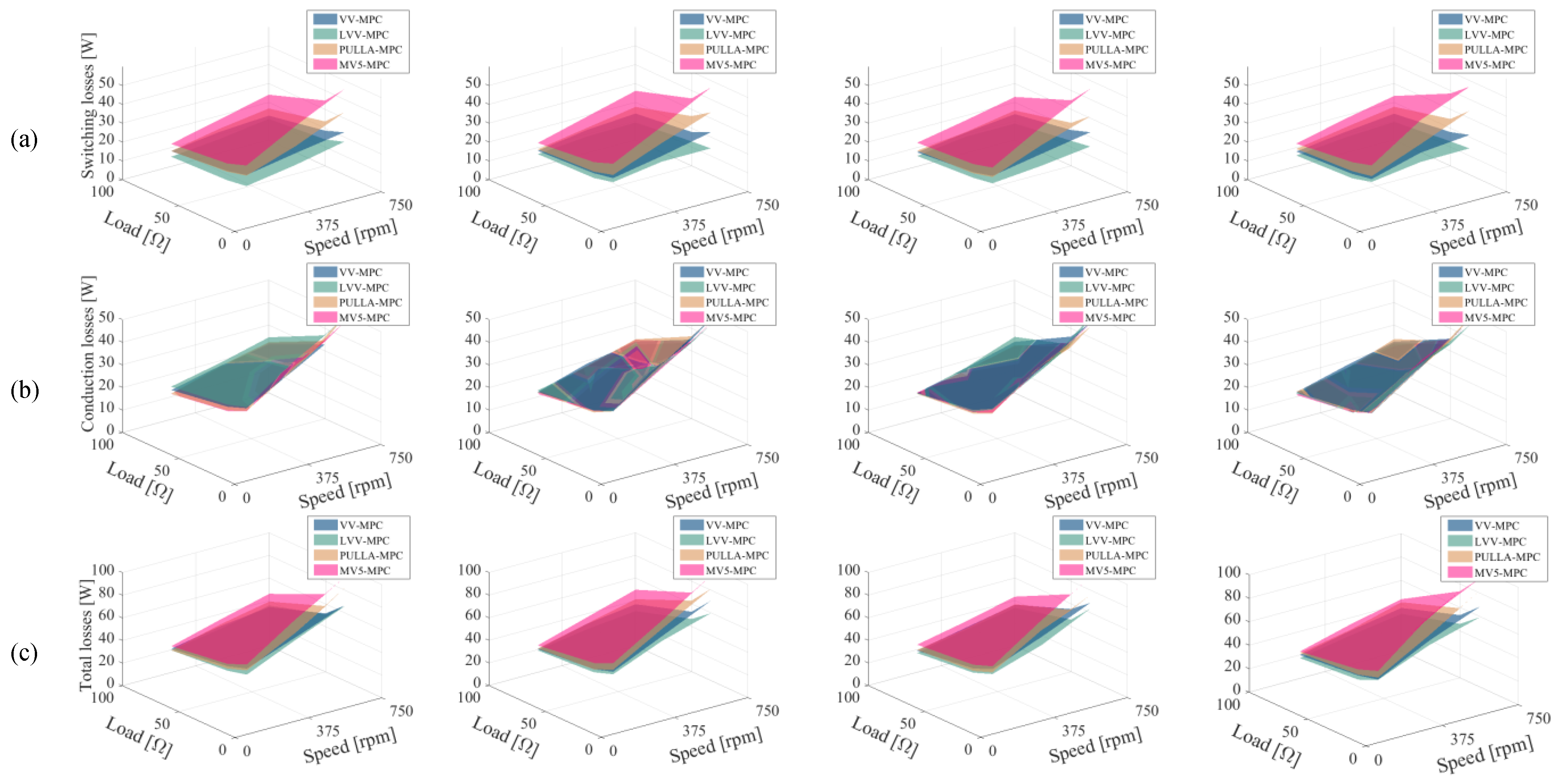
5.2.3. Power Losses
6. Conclusions
- Item 1: Current quality
- MV5 is the best choice when MPC is to be applied in machines with a low stator impedance. As a rule of thumb, in this scenario, the x-y plane becomes very sensitive and hence the use of multiple switching states and variable times of application is advantageous.
- When the impedance of the stator becomes higher, the MPC strategies that use fewer voltage vectors (e.g., VV or LVV) can be more adequate since the THD becomes similar to MV5 but the switching frequency is reduced. It can be said that there is no mandatory need to use more switching states to satisfactorily reduce the value of the x-y currents.
- The differences in the RMS values of phase currents are non-significant regardless of the implemented control scheme or the employed electric drive.
- Item 2: Current tracking
- The current tracking in both planes (x-y and ) is highly jeopardized when the control methods use a low number of switching states (e.g., VV and LVV) and the impedance of the stator is very low (e.g., 6PH-IM1). Consequently, MV5 or PULLA would be the best candidate in this case.
- When the stator impedance is in the medium range (i.e., 6PH-IM3), the tracking error becomes much more similar to the different multi-vector strategies, and methods such as LVVs are more attractive because of their high utilization of the dc-link voltage and low switching frequency.
- When the utilization of the dc-link voltage is reaching the limit, as may happen in machines like 6PH-IM4, the insufficient voltage generates an unacceptable current tracking; hence, methods such as MV5 should be avoided (unless the application only requires low-speed operation).
- Item 3: Machine and VSC power losses
- Switching losses are lower in static multi-vector MPC strategies (e.g., VV and LVV) and they do not depend on the stator parameters but on the number and types of voltage vectors that are applied in each sampling period.
- Although Joule losses in the machine are dominant, the reduction in the switching losses in the case of LVV-MPC can be considered as an interesting benefit in high-speed/torque conditions.
Supplementary Materials
Author Contributions
Funding
Data Availability Statement
Conflicts of Interest
Appendix A
Predictive Machine Model Matrices
References
- Levi, E. Multiphase Electric Machines for Variable-Speed Applications. IEEE Trans. Ind. Electron. 2008, 55, 1893–1909. [Google Scholar] [CrossRef]
- Levi, E. Advances in Converter Control and Innovative Exploitation of Additional Degrees of Freedom for Multiphase Machines. IEEE Trans. Ind. Electron. 2016, 63, 433–448. [Google Scholar] [CrossRef]
- Lu, H.; Li, J.; Qu, R.; Ye, D. Fault-tolerant predictive current control with two-vector modulation for six-phase permanent magnet synchronous machine drives. IET Electr. Power Appl. 2018, 12, 169–178. [Google Scholar] [CrossRef]
- Lu, H.; Li, J.; Qu, R.; Ye, D.; Lu, Y. Fault-Tolerant Predictive Control of Six-Phase PMSM Drives Based on Pulsewidth Modulation. IEEE Trans. Ind. Electron. 2019, 66, 4992–5003. [Google Scholar] [CrossRef]
- Moraes, T.J.D.S.; Nguyen, N.K.; Semail, E.; Meinguet, F.; Guerin, M. Dual-Multiphase Motor Drives for Fault-Tolerant Applications: Power Electronic Structures and Control Strategies. IEEE Trans. Power Electron. 2018, 33, 572–580. [Google Scholar] [CrossRef]
- Abad, H.B.B.; Ojaghi, M.; Taheri, A. Extra Freedom Degrees of Six-Phase Induction Motors Used to Diagnose Stator Inter-Turn Faults. Electr. Power Components Syst. 2021, 49, 294–307. [Google Scholar] [CrossRef]
- Levi, E.; Jones, M.; Vukosavic, S.N. A series-connected two-motor six-phase drive with induction and permanent magnet machines. IEEE Trans. Energy Convers. 2006, 21, 121–129. [Google Scholar] [CrossRef]
- Levi, E.; Jones, M.; Vukosavic, S.N.; Toliyat, H.A. A novel concept of a multiphase, multimotor vector controlled drive system supplied from a single voltage source inverter. IEEE Trans. Power Electron. 2004, 19, 320–335. [Google Scholar] [CrossRef]
- Blaschke, F. The principle of field-orientation as applied to the new transvector closed-loop control system for rotating machine. Siemens Rev. 1972, 39, 217–220. [Google Scholar]
- Singh, G.K.; Nam, K.; Lim, S.K. A simple indirect field-oriented control scheme for multiphase induction machine. IEEE Trans. Ind. Electron. 2005, 52, 1177–1184. [Google Scholar] [CrossRef]
- Yepes, A.G.; Gandoy, J.D.; Toliyat, H.A. Improvement in DC-Link Utilization with Reduced Current and Torque Deterioration for Five-Phase Drives by Combination of Circulating-Current Filters and Simple Carrier-Based PWM Based on Closed-Form Expressions. IEEE Trans. Ind. Electron. 2021, 68, 960–971. [Google Scholar] [CrossRef]
- Robles, E.; Fernandez, M.; Andreu, J.; Ibarra, E.; Zaragoza, J.; Ugalde, U. Common-mode voltage mitigation in multiphase electric motor drive systems. Renew. Sustain. Energy Rev. 2022, 157, 111971. [Google Scholar] [CrossRef]
- Levi, E.; Bojoi, R.; Profumo, F.; Toliyat, H.A.; Williamson, S. Multiphase induction motor drives—A technology status review. IET Electr. Power Appl. 2007, 1, 489–516. [Google Scholar] [CrossRef]
- Hava, A.; Kerkman, R.; Lipo, T. Carrier-based PWM-VSI overmodulation strategies: Analysis, comparison, and design. IEEE Trans. Power Electron. 1998, 13, 674–689. [Google Scholar] [CrossRef]
- Lopez, O.; Alvarez, J.; Yepes, A.G.; Baneira, F.; Perez-Estevez, D.; Freijedo, F.D.; Doval-Gandoy, J. Carrier-Based PWM Equivalent to Multilevel Multiphase Space Vector PWM Techniques. IEEE Trans. Ind. Electron. 2020, 67, 5220–5231. [Google Scholar] [CrossRef]
- Holmes, G.; Lipo, T.; Lipo, T. Pulse Width Modulation for Power Converters: Principles and Practice; Wiley: Hoboken, NJ, USA, 2003. [Google Scholar]
- Carrasco, G.; Silva, C.A. Space Vector PWM Method for Five-Phase Two-Level VSI with Minimum Harmonic Injection in the Overmodulation Region. IEEE Trans. Ind. Electron. 2013, 60, 2042–2053. [Google Scholar] [CrossRef]
- Lim, C.S.; Levi, E.; Jones, M.; Rahim, N.A.; Hew, W.P. FCS-MPC-Based Current Control of a Five-Phase Induction Motor and its Comparison with PI-PWM Control. EEE Trans. Ind. Electron. 2014, 61, 149–163. [Google Scholar] [CrossRef]
- Arahal, M.; Satue, M.G.; Barrero, F.; Ortega, M.G. Adaptive Cost Function FCSMPC for 6-Phase IMs. Energies 2021, 14, 52222. [Google Scholar] [CrossRef]
- Bhowate, A.; Aware, M.; Sharma, S.; Tatte, Y. Predictive Torque Control for Five Phase Induction Motor Drive with Common Mode Voltage Reduction. In Proceedings of the International Power Electronics Conference, Niigata, Japan, 20–24 May 2018; pp. 1730–1735. [Google Scholar] [CrossRef]
- Luo, Y.; Liu, C. Multi-Vector-Based Model Predictive Torque Control for a Six-Phase PMSM Motor with Fixed Switching Frequency. IEEE Trans. Energy Convers. 2019, 34, 1369–1379. [Google Scholar] [CrossRef]
- Xue, C.; Song, W.; Feng, X. Finite control-set model predictive current control of five-phase permanent-magnet synchronous machine based on virtual voltage vectors. IET Electr. Power Appl. 2017, 11, 836–846. [Google Scholar] [CrossRef]
- Gonzalez-Prieto, A.; Gonzalez-Prieto, I.; Duran, M.J.; Aciego, J.J.; Salas-Biedma, P. Current Harmonic Mitigation Using a Multi-Vector Solution for MPC in Six-Phase Electric Drives. IEEE Access 2021, 9, 117761–117771. [Google Scholar] [CrossRef]
- Duran, M.; Gonzalez-Prieto, I.; Prieto, A.G.; Carrillo-Rios, J.; Aciego, J.J.; Salas-Biedma, P. Proportional Usage of Low-Level Actions in Model Predictive Control for Six-Phase Electric Drives. Energies 2021, 14, 4358. [Google Scholar] [CrossRef]
- Duran, M.J.; Gonzalez-Prieto, I.; Gonzalez-Prieto, A. Large virtual voltage vectors for direct controllers in six-phase electric drives. Int. J. Electr. Power Energy Syst. 2021, 125, 106425. [Google Scholar] [CrossRef]
- Gonzalez-Prieto, I.; Duran, M.J.; Aciego, J.J.; Martin, C.; Barrero, F. Model Predictive Control of Six-Phase Induction Motor Drives Using Virtual Voltage Vectors. IEEE Trans. Ind. Electron. 2018, 65, 27–37. [Google Scholar] [CrossRef]
- Duran, M.; Gonzalez-Prieto, I.; Gonzalez-Prieto, A.; Aciego, J.J. The Evolution of Model Predictive Control in Multiphase Electric Drives: A Growing Field of Research. IEEE Ind. Electron. Mag. 2022, 16, 29–39. [Google Scholar] [CrossRef]
- Goncalves, P.; Cruz, S.; Mendes, A. Multistage Predictive Current Control Based on Virtual Vectors for the Reduction of Current Harmonics in Six-Phase PMSMs. IEEE Trans. Energy Convers. 2021, 36, 1368–1377. [Google Scholar] [CrossRef]
- Tao, T.; Zhao, W.; He, Y.; Zhu, J.; Tan, H.; Xue, R. Multivector Predictive Current Control for Five-Phase PM Motor by Using Hybrid Duty Modulation Technology. IEEE Trans. Transp. Electrif. 2020, 6, 1603–1612. [Google Scholar] [CrossRef]
- Ayala, M.; Doval-Gandoy, J.; Rodas, J.; Gonzalez, O.; Gregor, R.; Rivera, M. A Novel Modulated Model Predictive Control Applied to Six-Phase Induction Motor Drives. IEEE Trans. Ind. Electron. 2021, 68, 3672–3682. [Google Scholar] [CrossRef]
- Yu, B.; Song, W.; Feng, J. Virtual Voltage Vector-Based Model Predictive Current Control for Five-Phase VSIs with Common-Mode Voltage Reduction. IEEE Trans. Transp. Electrif. 2021, 7, 706–717. [Google Scholar] [CrossRef]
- Goncalves, P.; Cruz, S.M.A.; Mendes, A.M.S. Bi-subspace predictive current control of six-phase PMSM drives based on virtual vectors with optimal amplitude. IET Electr. Power Appl. 2019, 13, 1672–1683. [Google Scholar] [CrossRef]
- Arahal, M.R.; Satue, M.G.; Barrero, F.; Martin, C. Online Adaptive Set of Virtual Voltage Vectors for Stator Current Regulation of a Six-Phase Induction Machine Using Finite State Model Predictive Controllers. Appl. Sci. 2023, 13, 4113. [Google Scholar] [CrossRef]
- Xue, Z.; Niu, S.; Chau, A.M.H.; Luo, Y.; Lin, H.; Li, X. Recent Advances in Multi-Phase Electric Drives Model Predictive Control in Renewable Energy Application: A State-of-the-Art Review. World Electr. Veh. J. 2023, 14, 44. [Google Scholar] [CrossRef]
- Frikha, M.A.; Croonen, J.; Deepak, K.; Benomar, Y.; Baghdadi, M.; Hegazy, O. Multiphase Motors and Drive Systems for Electric Vehicle Powertrains: State of the Art Analysis and Future Trends. Energies 2023, 16, 768. [Google Scholar] [CrossRef]
- Ehsani, M.; Singh, K.V.; Bansal, H.O.; Mehrjardi, R.T. State of the Art and Trends in Electric and Hybrid Electric Vehicles. Proc. IEEE 2021, 109, 967–984. [Google Scholar] [CrossRef]
- Ahmed, A.A.; Koh, B.K.; Lee, Y.I. A Comparison of Finite Control Set and Continuous Control Set Model Predictive Control Schemes for Speed Control of Induction Motors. IEEE Trans. Ind. Inform. 2018, 14, 1334–1346. [Google Scholar] [CrossRef]
- Xue, C.; Song, W.; Wu, X.; Feng, X. A Constant Switching Frequency Finite-Control-Set Predictive Current Control Scheme of a Five-Phase Inverter with Duty-Ratio Optimization. IEEE Trans. Power Electron. 2018, 33, 3583–3594. [Google Scholar] [CrossRef]
- Luo, Y.; Liu, C. A Simplified Model Predictive Control for a Dual Three-Phase PMSM with Reduced Harmonic Currents. IEEE Trans. Ind. Electron. 2018, 65, 9079–9089. [Google Scholar] [CrossRef]
- Liu, Z.; Li, Y.; Zheng, Z. A review of drive techniques for multiphase machines. CES Trans. Electr. Mach. Syst. 2018, 2, 243–251. [Google Scholar] [CrossRef]
- Liu, S.; Liu, C. Virtual-vector-based robust predictive current control for dual three-phase PMSM. IEEE Trans. Ind. Electron. 2021, 68, 2048–2058. [Google Scholar] [CrossRef]
- Martin, C.; Bermudez, M.; Barrero, F.; Arahal, M.R.; Kestelyn, X.; Duran, J. Sensitivity of predictive controllers to parameter variation in five-phase induction motor drives. Control Eng. Pract. 2017, 68, 23–31. [Google Scholar] [CrossRef]
- Bogado, B.; Barrero, F.; Arahal, M.R.; Toral, S.; Levi, E. Sensitivity to electrical parameter variations of Predictive Current Control in multiphase drives. In Proceedings of the IECON 2013—39th Annual Conference of the IEEE Industrial Electronics Society, Vienna, Austria, 10–13 November 2013; pp. 5215–5220. [Google Scholar] [CrossRef]
- Guo, L.; Chen, M.; Li, Y.; Wang, P.; Jin, N.; Wu, J. Hybrid Multi-Vector Modulated Model Predictive Control Strategy for Voltage Source Inverters Based on a New Visualization Analysis Method. IEEE Trans. Transp. Electrif. 2023, 9, 8–21. [Google Scholar] [CrossRef]
- Sun, J.; Yang, Y.; Chen, R.; Zhang, X.; Lim, C.S.; Rodriguez, J. An efficient multi-vector based model predictive current control for PMSM drive. CPSS Trans. Power Electron. Appl. 2023, 1–11. [Google Scholar] [CrossRef]
- Yang, Y.; Wen, H.; Fan, M.; He, L.; Xie, M.; Chen, R.; Norambuena, M.; Rodriguez, J. Multiple-Voltage-Vector Model Predictive Control with Reduced Complexity for Multilevel Inverters. IEEE Trans. Transp. Electrif. 2020, 6, 105–117. [Google Scholar] [CrossRef]
- Deng, W.; Zhang, Q.; Xie, W. An Enhanced Virtual Vector-Based Model Predictive Control for PMSM Drives to Reduce Common-Mode Voltage Considering Dead Time Effect. IEEE J. Emerg. Sel. Top. Power Electron. 2023, 11, 4659–4668. [Google Scholar] [CrossRef]
- Che, H.S.; Levi, E.; Jones, M.; Hew, W.P.; Rahim, N.A. Current control methods for an asymmetrical six-phase induction motor drive. IEEE Trans. Power Electron. 2014, 29, 407–417. [Google Scholar] [CrossRef]
- Wang, H.; Wu, X.; Zheng, X.; Yuan, X. Virtual Voltage Vector Based Model Predictive Control for a Nine-Phase Open-End Winding PMSM with a Common DC Bus. IEEE Trans. Ind. Electron. 2022, 69, 5386–5397. [Google Scholar] [CrossRef]
- Gonzalez, J.O.; Perez-Estevez, D.; Wu, J.D.G.R.; Mawby, P.; Alatise, O. Power Device Losses in Two-Level Converters with Direct Current Controllers for Grid Connected Applications. In Proceedings of the 2021 IEEE Energy Conversion Congress and Exposition (ECCE), Vancouver, BC, Canada, 10–14 October 2021; pp. 3154–3159. [Google Scholar] [CrossRef]
- Zhao, Y.; Lipo, T.A. Space vector PWM control of dual three-phase induction machine using vector space decomposition. IEEE Trans. Ind. Appl. 1995, 31, 1100–1109. [Google Scholar] [CrossRef]
- Goncalves, P.; Cruz, S.; Mendes, A. Finite Control Set Model Predictive Control of Six-Phase Asymmetrical Machines—An Overview. Energies 2019, 12, 4693. [Google Scholar] [CrossRef]
- Xu, Z.; Wang, Z.; Wang, X.; Cheng, M. Predictive current control method for dual three-phase PMSM drives with reduced switching frequency and low-computation burden. IET Electr. Power Appl. 2020, 14, 668–677. [Google Scholar] [CrossRef]
- Yang, G.; Hussain, H.; Li, S.; Zhang, X.; Yang, J.; Lee, C.H.T. Design and Analysis of Universal Natural Fault-Tolerant SVPWM Strategy with Simplified Fault Diagnosis for Multiphase Motor Drives. IEEE J. Emerg. Sel. Top. Power Electron. 2023, 11, 4340–4354. [Google Scholar] [CrossRef]
- Wang, H.; Wu, X.; Zheng, X.; Yuan, X. Model Predictive Current Control of Nine-Phase Open-End Winding PMSMs with an Online Virtual Vector Synthesis Strategy. IEEE Trans. Ind. Electron. 2023, 70, 2199–2208. [Google Scholar] [CrossRef]
- Kindl, V.; Cermak, R.; Ferkova, Z.; Skala, B. Review of Time and Space Harmonics in Multi-Phase Induction Machine. Energies 2020, 13, 496. [Google Scholar] [CrossRef]
- Abdel-Khalik, A.S.; Abdel-Majeed, M.S.; Ahmed, S. Effect of Winding Configuration on Six-Phase Induction Machine Parameters and Performance. IEEE Access 2020, 8, 223009–223020. [Google Scholar] [CrossRef]
- Rodriguez, J.; Garcia, C.; Mora, A.; Davari, S.A.; Rodas, J.; Valencia, D.F.; Elmorshedy, M.; Wang, F.; Zuo, K.; Tarisciotti, L.; et al. Latest Advances of Model Predictive Control in Electrical Drives-Part II: Applications and Benchmarking with Classical Control Methods. IEEE Trans. Power Electron. 2022, 37, 5047–5061. [Google Scholar] [CrossRef]
- Che, H.S.; Hew, W.P. Dual three-phase operation of single neutral symmetrical six-phase machine for improved performance. In Proceedings of the IECON 2015—41st Annual Conference of the IEEE Industrial Electronics Society, Yokohama, Japan, 9–12 November 2015; pp. 001176–001181. [Google Scholar] [CrossRef]
- Yepes, A.G.; Doval-Gandoy, J.; Baneira, F.; Toliyat, H.A. Comparison of stator winding connections in multiphase drives under healthy operation and with one open converter leg. IET Electr. Power Appl. 2020, 14, 584–596. [Google Scholar] [CrossRef]
- Shawier, A.; Habib, A.; Mamdouh, M.; Abdel-Khalik, A.S.; Ahmed, K.H. Assessment of Predictive Current Control of Six-Phase Induction Motor with Different Winding Configurations. IEEE Access 2021, 9, 81125–81138. [Google Scholar] [CrossRef]
- Hafezi, H.; Faranda, R. A New Approach for Power Losses Evaluation of IGBT/Diode Module. Electronics 2021, 10, 280. [Google Scholar] [CrossRef]
- Yepes, A.G.; Riveros, J.A.; Doval-Gandoy, J.; Barrero, F.; Lopez, Ó.; Bogado, B.; Jones, M.; Levi, E. Parameter Identification of Multiphase Induction Machines with Distributed Windings—Part 1: Sinusoidal Excitation Methods. IEEE Trans. Energy Convers. 2012, 27, 1056–1066. [Google Scholar] [CrossRef]
- Riveros, J.A.; Yepes, A.G.; Barrero, F.; Doval-Gandoy, J.; Bogado, B.; Lopez, O.; Jones, M.; Levi, E. Parameter Identification of Multiphase Induction Machines with Distributed Windings—Part 2: Time-Domain Techniques. IEEE Trans. Energy Convers. 2012, 27, 1067–1077. [Google Scholar] [CrossRef]


| Ref. | Acronym | Nature | Switching States per Control Action | Null-Avg x-y Volt. | Inst. x-y Harm. |
|---|---|---|---|---|---|
| [26] | VV-MPC | Offline | 2 |  | ✗ |
| [25] | LVV-MPC | Offline | 2 | ✗ | |
| [24] | PULLA-MPC | Online | 3 | | |
| [27] | MV5-MPC | Online | 5 | | |
| VV-MPC | LVV-MPC | PULLA-MPC | MV5-MPC |
|---|---|---|---|
| 92.8 % | 96.2 % | 96.2 % | 89.9 % |
| Dc-Link Voltage = 300 V; Control Frequency 10 kHz | ||||
|---|---|---|---|---|
| Parameter | 6PH-IM1 | 6PH-IM2 | 6PH-IM3 | 6PH-IM4 |
| 4.2 | 14.2 | 4.2 | 14.2 | |
| 3 | 3 | 3 | 3 | |
| (mH) | 370 | 370 | 370 | 370 |
| (mH) | 4.5 | 4.5 | 24.5 | 24.5 |
| (mH) | 55.12 | 55.12 | 55.12 | 55.12 |
| 6PH-IM1 | 6PH-IM2 | 6PH-IM3 | 6PH-IM4 | |||||
|---|---|---|---|---|---|---|---|---|
| Scheme | THD | THD | THD | THD | ||||
| VV-MPC | ✗✗ | ✗✗ | ✗✗ | ✗✗ | - | - | - | - |
| LVV-MPC | ✗✗✗ | ✗✗✗ | ✗✗ | ✗✗ | ✗ | ✗ | - | - |
| PULLA-MPC | ✗ | ✗✗ | ✗ | ✗ | - | ✗ | - | - |
| MV5-MPC | | | | | | | - | - |
| 6PH-IM1 | 6PH-IM2 | 6PH-IM3 | 6PH-IM4 | |||||
|---|---|---|---|---|---|---|---|---|
| Scheme | MSE | MSE | MSE | MSE | MSE | MSE | MSE | MSE |
| VV-MPC | ✗✗ | ✗✗ | ✗ | ✗ | | | | |
| LVV-MPC | ✗✗✗ | ✗✗ | ✗ | ✗ | - | - | | |
| PULLA-MPC | | | | ✗ | | ✗ | ✗ | ✗✗ |
| MV5-MPC | | | | ✗✗ | ✗ | ✗✗✗ | ✗✗ | ✗✗✗ |
Disclaimer/Publisher’s Note: The statements, opinions and data contained in all publications are solely those of the individual author(s) and contributor(s) and not of MDPI and/or the editor(s). MDPI and/or the editor(s) disclaim responsibility for any injury to people or property resulting from any ideas, methods, instructions or products referred to in the content. |
© 2024 by the authors. Licensee MDPI, Basel, Switzerland. This article is an open access article distributed under the terms and conditions of the Creative Commons Attribution (CC BY) license (https://creativecommons.org/licenses/by/4.0/).
Share and Cite
Aciego, J.J.; Gonzalez-Prieto, I.; Duran, M.J.; Gonzalez-Prieto, A.; Carrillo-Rios, J. Guiding the Selection of Multi-Vector Model Predictive Control Techniques for Multiphase Drives. Machines 2024, 12, 115. https://doi.org/10.3390/machines12020115
Aciego JJ, Gonzalez-Prieto I, Duran MJ, Gonzalez-Prieto A, Carrillo-Rios J. Guiding the Selection of Multi-Vector Model Predictive Control Techniques for Multiphase Drives. Machines. 2024; 12(2):115. https://doi.org/10.3390/machines12020115
Chicago/Turabian StyleAciego, Juan Jose, Ignacio Gonzalez-Prieto, Mario Javier Duran, Angel Gonzalez-Prieto, and Juan Carrillo-Rios. 2024. "Guiding the Selection of Multi-Vector Model Predictive Control Techniques for Multiphase Drives" Machines 12, no. 2: 115. https://doi.org/10.3390/machines12020115