Article

A Novel Hole System Dimension Analysis Tool Based on the Combination of the Process Path and Design Path

School of Mechanical and Power Engineering, Zhengzhou University, Zhengzhou 450001, China
*
Author to whom correspondence should be addressed.
Machines 2024, 12(4), 245; https://doi.org/10.3390/machines12040245
Submission received: 25 February 2024 / Revised: 3 April 2024 / Accepted: 4 April 2024 / Published: 8 April 2024
(This article belongs to the Section Machine Design and Theory)

Abstract

:
In the calculation of process dimensions in the machining of porous parts, the traditional method is complicated in the establishment of the dimensional chain, it is easy to make mistakes in the judgment of increasing and decreasing loops, and there is difficulty in the calculation process; thus, this paper puts forward a method that combines the process path with the design path to analyze the hole system dimensions in response to these problems. First of all, the combination of the process path and design path is used to establish a system of vector equations and, according to the system of vector equations, to establish a matrix model to calculate the process dimensions based on the system of vector equations to construct the process dimensional chain and the dimensional chain function; then, the principle of differentiation is used to carry out a tolerance analysis of the process dimensions, which avoids the drawing of dimensional chain diagrams and the judgement of the incremental/decremental loops. Finally, the development of a process dimension analysis tool for hole system dimensions is completed based on CATIA CAA. In order to verify the effectiveness of the proposed method, the analysis tool was used to solve the three labeling methods of the hole system dimensions of porous parts and compared with the results calculated using the traditional method, and it was found that some of the tolerance results obtained by the proposed method were enlarged by about 50%, which is more in line with the actual production situation. Finally, in order to verify the accuracy of the tool’s calculation results, three porous parts were machined according to the process dimensions and tolerances calculated by the tool, and the center distance of each hole was measured by a coordinate meter. These measurements were compared and analyzed with the design dimensions specified in the engineering drawings, and it was found that the center distances of the holes were in full compliance with the design requirements.

1. Introduction

The quality problems of most finished parts in mechanical manufacturing are caused by dimension problems [1]. The calculation of process dimensions and tolerance analysis are very important in the process of product design and manufacturing. Parts such as shells and boxes are often encountered in machining, and these parts usually have several holes with mutual location requirements. Such parts are generally machined on the machining center or the coordinate boring machine, and the center distance and tolerance between holes are guaranteed by the movement accuracy of the horizontal and vertical coordinates of the workbench or boring head [2]. Therefore, in the machining process of porous parts, it is necessary to rely on the plane dimension chain theory to convert the hole system center distance dimension and tolerance into the coordinate dimension and tolerance. These directly controlled dimensions in the boring process are process dimensions. This inevitable solution process makes the processing of porous parts more complex. Traditionally, these calculations are performed manually, time-consuming, and prone to errors. In recent years, computer-assisted mechanical design has been developing rapidly, but most of these designs are focused on model design and structural analysis [3]. If the computer technology can be applied to the solution of the process size in the processing of porous parts, the automation of this calculation can save a lot of labor and time costs. CATIA is widely used in aerospace, automotive engineering, and other fields, often involving the design and production of complex porous parts. The development of process size analysis tools integrated in CATIA avoids the conversion requirements of the drawing format in the processing process, makes the calculation of process size more convenient, and improves the consistency and efficiency from design to the manufacturing process.
In the study of the calculation and tolerance analysis of planar dimensional chains, the following studies are worthy of mention: Xue et al. [4] discussed the tolerance assignment method for process dimensions containing angles in the calculation of planar dimensional chains based on a discrete cost tolerance model. Gonzalez et al. [5] proposed an equivalent conversion of dimensional tolerances in two dimensions, established a dimensional model from a two-dimensional dimensional diagram to a two-dimensional dimensional chain containing dimensional, angular and directional tolerances, and evaluated the equivalent tolerances by considering the theory of accumulation of variance and the theory of accumulation of deviation. P. Ji et al. [6] proposed a computational method of calculating the average working dimensions in the inverse direction, which was obtained by using an algebraic approach in which the inverse chain matrix containing the inverse tolerance chain and the forward chain matrix of the forward tolerance chain are derived from the inverse chain matrix, which in turn assigns the tolerances to the dimensional work size. Li et al. [7] investigated the circular dimensional chain and the parallel chain in the machining dimensional chain to provide a generalized solution for the dimensional problems in the machining process. P. Ji et al. [8] extended the algebraic method of the one-dimensional tolerance map and proposed out an algebraic method for building dimensional chains for angular tolerance diagrams, discussing the problems and features of angular tolerance diagrams and the new algebraic method. These studies play an important role in the calculation and tolerance analysis of planar dimensional chains, but these methods still need to draw the dimensional chain and perform the discrimination of increasing and decreasing the loop, which is a complicated and error-prone process.
Many scholars have investigated process planning and structural simulation using computer-aided design. Pan et al. [9] introduced virtual cutting quantities to reflect dimensional variations due to indirect machining and proposed a computer-aided design method to automatically identify dimensional chains associated with regular or virtual cuts. Masyagin et al. [10], in response to the inefficiency of the workpieces in the cutting process, analyzed an adaptive example of calculating linear process dimensions and concluded that by calculating linear technical dimensions and adjusting them, the actual allowance at each transition can be determined. Pang et al. [11] used the projection method and Extremum method for the calculation of planar dimensional chains and implemented a computer-aided design of a planar dimensional chain solver system by the secondary development of UG. Liu et al. [12] investigated the mathematical model of dimensional chains and used AutoCAD secondary development technology to establish a computer-aided analysis and calculation model for dimensional chain margin calculation. Lin et al. [13] used a network model to identify objects in drawings, such as dimensions, tolerances, functional frames, and geometric symbols. Jiang et al. [14] introduced the assembly dimensional chain into the structural design of different cycloid-pinion systems and established a cycloid-pinion system dynamics model and friction loss model to verify the necessity of a pinion sleeve. The application of computer-aided design in mechanical dimensioning is very extensive, but there are few applications in the calculation of the process dimensioning of porous parts.
For the computer-aided design integrated in CATIA, Dong et al. [15] proposed a feature-based inverse modeling method that can reflect the design intent of the tread structure and developed a feature-based inverse modeling system for tire structural design based on the CATIA V5 platform. F Yougao et al. [16] proposed an information element-based automatic generation method of assembly dimensional chain for the automatic generation of assembly dimensional chains and developed an assembly dimensional chain system based on the CATIA V5 platform. Fang et al. [17] built a shaft system component development platform through CATIA CAA secondary development technology and introduced the system operation method with a typical component as an example. Zhang et al. [18] proposed a parametric modeling method for curved cam based on CATIA/CAA and developed a feature-based inverse modeling system for tire structure design through CATIA secondary development. Through the secondary development of CATIA, the parametric modeling of the arc cam is realized by using the modeling method based on a feature model. It can be seen that the functional modules generated by CATIA CAA development are closely integrated with the original system, have good human-computer interaction, are easy to be used by end users, and have an important position in computer-aided mechanical design.
The above studies play an important role in the analysis and calculation of planar dimensional chain, but these methods are only up to the dimensional relationship, and cannot cover the detailed description of the process sequence and machining datum [4,6,7]; at the same time, the drawing of the dimensional chain diagrams are cumbersome, and the identification of increase and decrease in the loop is prone to errors, and the computation process is complicated, which is not conducive to the computer-aided design [11,12]; the manual computation is time-consuming and low-efficiency, and the artificial errors can easily affect the accuracy of calculation [5,8]. In the face of these limitations, this paper carries out an in-depth study on the calculation of process dimensions of the hole system during the machining of porous parts, using CATIA CAA technology to carry out research and development based on the combination of process paths and design paths to analyze hole system dimensions, and the main content of the study is shown in Figure 1:
(1)
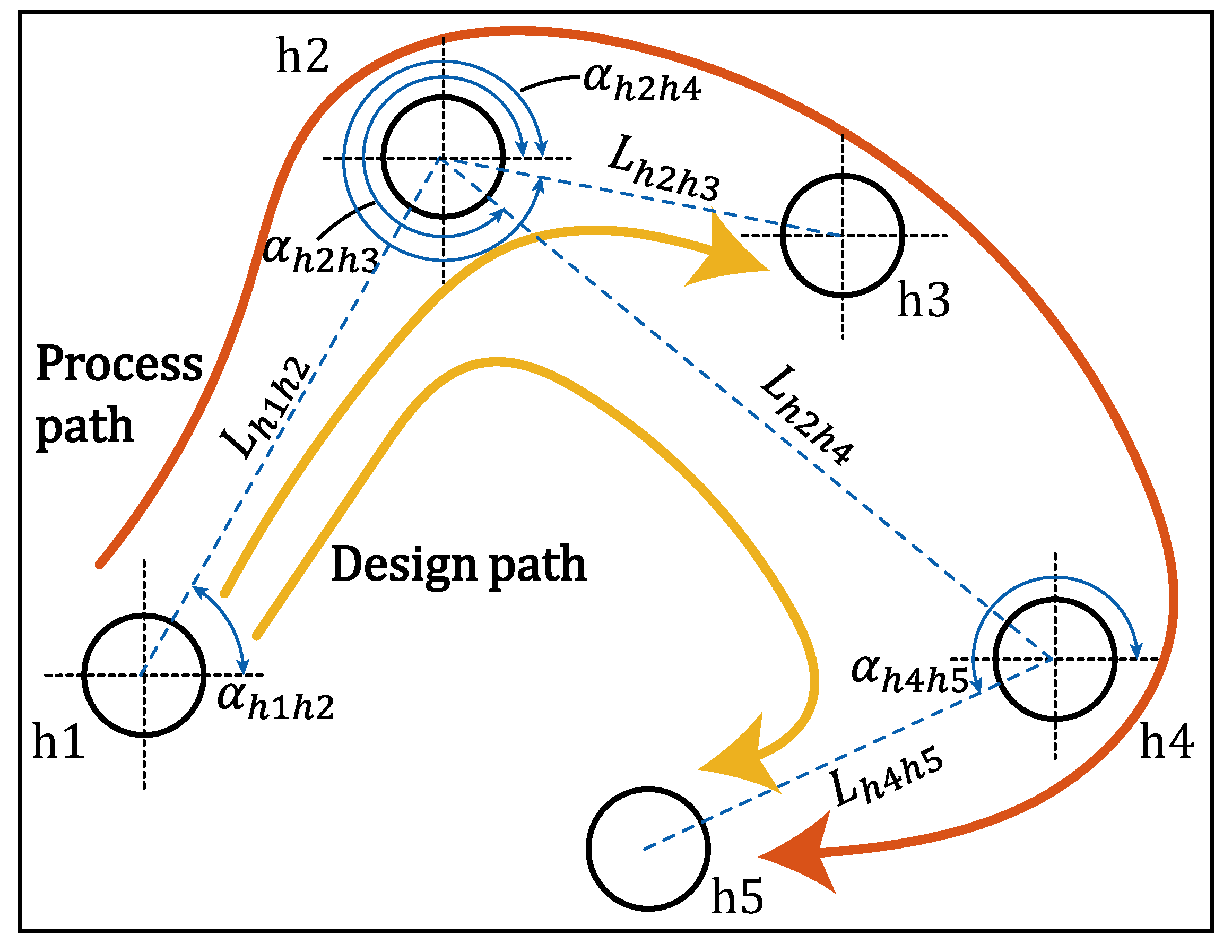
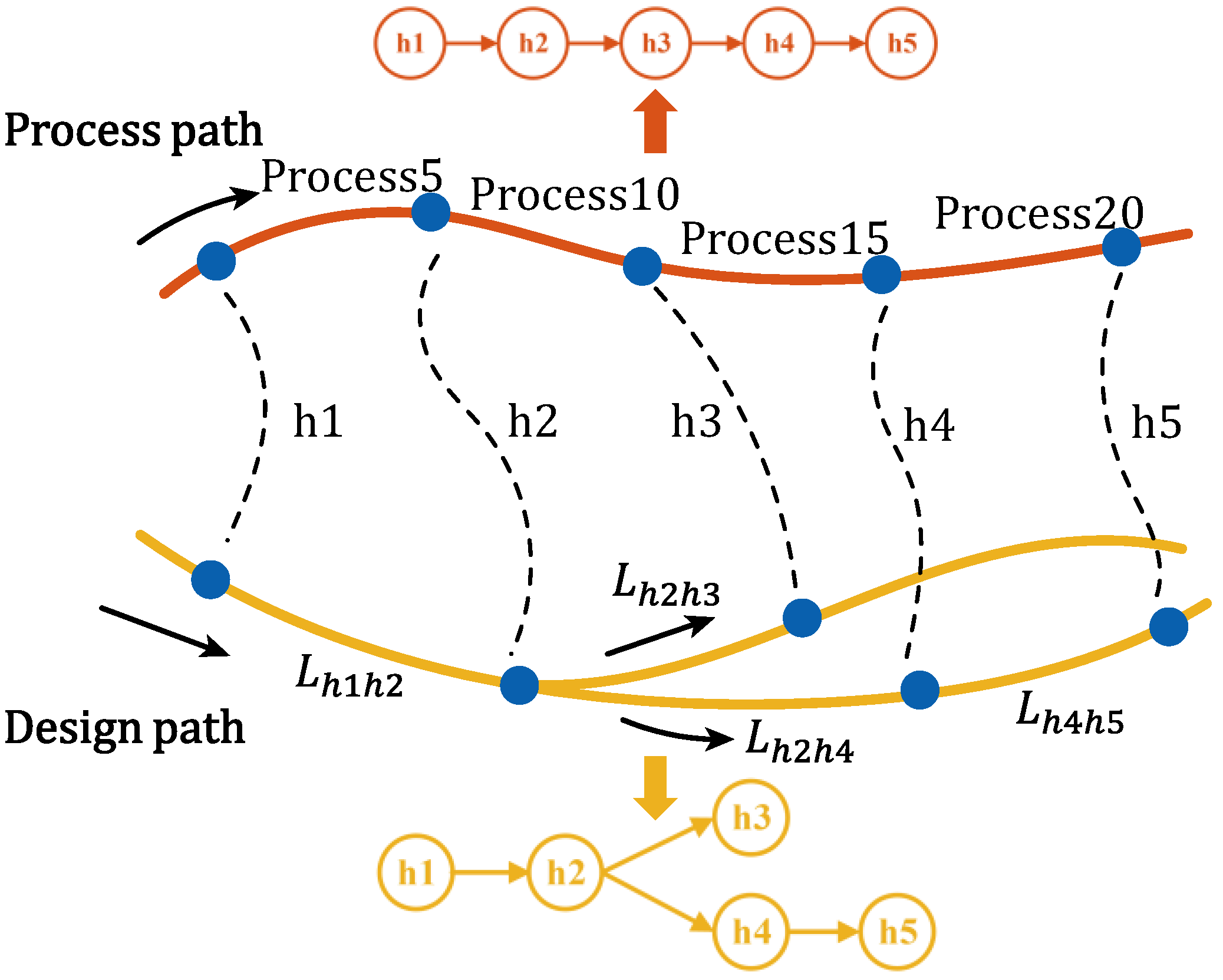
The process path is combined with the design path to establish a system of vector equations and generate the corresponding mathematical model to calculate the process dimensions, obtaining the process dimensions with vector characteristics, which expresses the dimensional relationship and also clearly expresses the process sequence and machining datum;
(2)
Based on the system of vector equations established by combining the process path and the design path, the process dimension chain and the dimension chain function are directly generated, and the differential principle is applied to calculate the tolerance of process dimensions, which avoids the drawing of the dimension chain diagram and the judgment of the increase or decrease in the rings. By determining the number of rings in the dimensional chain and adopting different calculation methods to calculate the tolerance of process dimensions, the tolerance range is enlarged on the basis of guaranteeing the accuracy, which is more in line with the actual production situation;
(3)
CATIA CAA secondary development technology is used to establish a set of automated calculation systems for the dimensions of the process system for the machining of hole parts, to make up for the shortcomings of manual calculations that are prone to errors and inefficiency.
The first chapter of this paper explains in detail the mathematical modeling and calculation of process dimensions and tolerances. The second chapter describes the design and implementation of the automated calculation system. The third chapter uses the system to analyze a typical example and verify the feasibility of the system. At last, the content of the article is summarized.

2. Calculation of Process Dimensions and Tolerances of Process Dimensions

The ultimate goal of machining is to ensure the design dimension and accuracy of the parts, the design dimension and accuracy is guaranteed by the process dimension and tolerance, and different process sequences will affect the tolerance design of the process dimension. Therefore, in order to solve the process dimensions and tolerances of porous parts, this paper proposes to combine the design path with the process path to calculate the process dimensions and tolerances of the hole system. First, a system of vector equations is generated by combining the design path and the process path, and a mathematical model is built based on the system of vector equations to calculate the process dimensions. Secondly, the process dimension chain and the dimensional chain function are established according to the system of vector equations, and the differential principle is applied to solve the tolerance of the process dimensions.

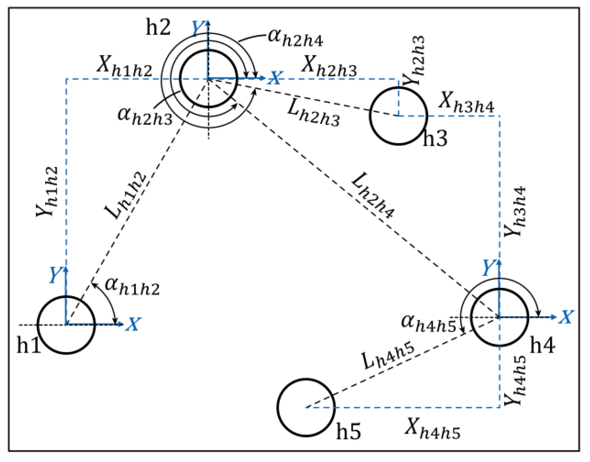
2.1. Mathematical Modeling of Dimensions

In order to accurately express the dimensional relationships and machining sequence, this paper uses h 1 ,   h 2 ,   h 3 ,   h 4 , etc., to mark the hole center of each hole in the part, in the numerical order that is the processing order of the holes; with L to indicate the hole center distance dimension, such as between the hole h 1 and hole h 2 dimensions with L h 1 h 2 ; with α to indicate the two holes in the center of the line with the X-axis in the positive direction of the angle, such as the related angular dimensions and L h 1 h 2 is expressed in terms of α h 1 h 2 . Figure 2 is a typical multi-hole parts of the dimension relationship diagram. The process route for the hole system part shown in Figure 2 is shown below:
Process 5: Rough Boring. The reference hole is h1 and the machining hole is h2;
Process 10: Rough Boring. The reference hole is h2 and the machining hole is h3;
Process 15: Rough Boring. The reference hole is h3 and the machining hole is h4;
Process 20: Rough Boring. The reference hole is h4 and the machining hole is h5.
Porous parts are usually machined on boring machines or machining centers, and the holes that are machined first are the machining reference for the holes that are machined later. The machining reference is placed at the beginning of the line segment, the arrow at the end of the line segment points to the hole being machined, and, according to the order of processing, the holes are added in order to form the process path of the hole machining.
In the design drawings of porous parts, often with the center distance dimension and angular dimension to mark the positional relationship between the various holes, such dimensions are called design dimensions. The design path is constructed in the same way as the process path. The design path is formed by picking up the hole elements at the two endpoints of the hole center distance dimension in the design dimension and drawing them in sequence.
Figure 3 describes the design path and process path for the porous part shown in Figure 2.
In the machining process, it is necessary to transform the design dimension into the process dimension; in the transformation process, it is necessary to ensure the center distance dimension and tolerance between the hole system, but also to follow the process sequence when the hole is machined, so it is proposed to combine the process path with the design path to establish a mathematical model to solve the process dimension and tolerance when the hole is machined. Each target dimension in the design path has its own process path, and the mathematical model between the dimensions is established by finding the relationship between them through the path. For example, in the process path of design path h 2 h 4 is h 2 h 3 h 4 , which is expressed as h 2 h 4 = h 2 h 3 + h 3 h 4 by the vector equation, the left side of the equal sign is the design path, and the right side of the equal sign is the process path related to this design path. The mathematical model of the design path and process path is established according to Figure 3, as shown in the system of vectors in Equation (1).
h 1 h 2 = h 1 h 2 h 2 h 3 = h 2 h 3 h 2 h 4 = h 2 h 3 + h 3 h 4 h 4 h 5 = h 4 h 5

2.2. Calculation of Process Dimensions

When calculating the process dimension, a coordinate system is established with the center of each hole as the machining reference as the origin, as shown in Figure 4. Each coordinate axis is oriented in the same direction to avoid commutation, and the direction is the same as that of the right-hand Cartesian coordinate system. The coordinate dimension of the design dimension L in the X-axis direction is denoted as X , while that in the Y-axis direction is denoted as Y . For example, the hole center distance dimension L h 1 h 2 in the X-axis is denoted as X h 1 h 2 , and in the Y-axis is denoted as Y h 1 h 2 . The system of vector equations in (1) is projected to the X-axis and Y-axis directions, and is written as matrix equations in Equations (2) and (3).
X h 1 h 2 = X h 1 h 2 X h 2 h 3 = X h 2 h 3 X h 2 h 4 = X h 2 h 3 + X h 3 h 4 X h 4 h 5 = X h 4 h 5 X h 1 h 2 X h 2 h 3 X h 2 h 4 X h 4 h 5 = 1 0 0 0 0 1 0 0 0 1 1 0 0 0 0 1 X h 1 h 2 X h 2 h 3 X h 3 h 4 X h 4 h 5
Y h 1 h 2 = Y h 1 h 2 Y h 2 h 3 = Y h 2 h 3 Y h 2 h 4 = Y h 2 h 3 + Y h 3 h 4 Y h 4 h 5 = Y h 4 h 5 Y h 1 h 2 Y h 2 h 3 Y h 2 h 4 Y h 4 h 5 = 1 0 0 0 0 1 0 0 0 1 1 0 0 0 0 1 Y h 1 h 2 Y h 2 h 3 Y h 3 h 4 Y h 4 h 5
According to the vector projection and trigonometric formulas, the solution yields the coordinate dimensions of the four design dimensions L h 1 h 2 , L h 2 h 3 , L h 2 h 4 , L h 4 h 5 as X h 1 h 2 , Y h 1 h 2 ; X h 2 h 3 , Y h 2 h 3 ; X h 2 h 4 , Y h 2 h 4 ; X h 4 h 5 , Y h 4 h 5 . Substituting these values into the system of Equations (2) and (3) yields the process dimensions required for hole machining: X h 1 h 2 , Y h 1 h 2 ; X h 2 h 3 , Y h 2 h 3 ; X h 3 h 4 , Y h 3 h 4 ; X h 4 h 5 , Y h 4 h 5 .

2.3. Calculation of Tolerances of Process Dimensions

Based on the above analysis, it can be seen that the fully correlated dimensional mathematical model established based on the process path and design path can solve all process dimensions at once, which provides a data basis for the differential method to solve the tolerance of process dimensions [19]. The design dimension of a part is indirectly realized by the process dimension, so this paper proposes the concept of a process dimensional chain for porous parts. The process dimensional chain takes the design dimension as the closed loop and the process dimensions that form the design dimension as the constituent loops. According to the design path and process path, the dimensional chain can be constructed directly and the dimensional chain equations can be generated to calculate the tolerance without drawing the dimensional chain diagram, which avoids the setup of closed loops in the dimensional chain as well as the judgment of increasing and decreasing loops.
The process dimensional chain is built based on the system of vectors in Equation (1) in Section 2.1, and one process dimension chain can be built for each vector equation. There are four vector equations in the system of vectors in Equation (1), and four process dimensional chains can be constructed:
h 1 h 2 = h 1 h 2 : L h 1 h 2 X h 1 h 2 Y h 1 h 2
h 2 h 3 = h 2 h 3 : L h 2 h 3 X h 2 h 3 Y h 2 h 3
h 2 h 4 = h 2 h 3 + h 3 h 4 : L h 2 h 4 X h 2 h 3 Y h 2 h 3 X h 3 h 4 Y h 3 h 4
h 4 h 5 = h 4 h 5 : L h 4 h 5 X h 4 h 5 Y h 4 h 5
After constructing the process dimensional chain, the dimensional chain function is established according to the geometric relationship between the constituent ring and the closed loop, and the tolerance is solved according to the differential method. The dimensional chain function is
L h i h j = i n ξ X h i h i + 1 2 + i n ξ Y h i h i + 1 2
In the formula: L h i h j is the design size; X h i h ( i + 1 ) , Y h i h ( i + 1 ) is the process size; n = j 1 ; ξ is the coefficient, when X h i h ( i + 1 ) , Y h i h ( i + 1 ) , and L h i h j are projected to the coordinate axis of the size of X h i h j , Y h i h j of the same positive and negative, ξ = 1 , when the positive and negative are different, ξ = 1 .
We calculate the total differential of dimension chain function and write the total differential of Formula (4):
d L h i h j = i = 1 n L h i h ( i + 1 ) X h i h ( i + 1 ) d X h i h ( i + 1 ) + i = 1 n L h i h ( i + 1 ) Y h i h ( i + 1 ) d Y h i h ( i + 1 )
When the number of dimensional chain rings is small, the Extremum method is used to calculate the dimensional chain tolerance in order to ensure accuracy; when the production batch is large or the number of dimensional chain rings is greater than 4, the probabilistic method is used to calculate the results; the calculation results are more in line with the reality, and it can be enlarged to manufacture tolerance and facilitate the processing [20].
We replace the variables d L h i h j , d X h i h ( i + 1 ) , and d Y h i h ( i + 1 ) in Equation (5) with the closed loop tolerance L hihj and each of the constituent ring tolerances X hih ( i + 1 ) and Y hih ( i + 1 ) . Because the tolerance values are always positive, we take each transfer function L h i h ( i + 1 ) X h i h ( i + 1 ) and L h i h ( i + 1 ) Y h i h ( i + 1 ) as an absolute value. According to the Extremum method of calculating the dimensional chain tolerance of the basic formula, the closed loop tolerance is equal to the sum of the tolerance values of the constituent rings, and Equation (5) becomes
T h i h j = i = 1 n L h i h ( i + 1 ) X h i h ( i + 1 ) T X h i h ( i + 1 ) + i = 1 n L h i h ( i + 1 ) Y h i h ( i + 1 ) T Y h i h ( i + 1 )
According to the basic formula for calculating dimensional chain tolerances by the probabilistic method, the square of the closed loop tolerance is equal to the sum of the squares of the tolerances of the individual constituent loops, and Equation (5) becomes
T h i h j 2 = i = 1 n L h i h ( i + 1 ) X h i h ( i + 1 ) 2 T 2 X h i h ( i + 1 ) + i = 1 n L h i h ( i + 1 ) Y h i h ( i + 1 ) 2 T 2 Y h i h ( i + 1 )
Considering the similarity of the error-generating conditions of the coordinate displacement of the same CNC machine tool, it can be set that the errors of the constituent rings in the process dimensional chain are equal, so the equation can be supplemented:
T X h i h ( i + 1 ) = T Y h i h ( i + 1 )
The generated process dimensional chain is calculated respectively. Firstly, the number of loops of the process dimensional chain is determined: when the number of loops of the dimensional chain is less than or equal to 4, the process dimensional tolerance calculation is carried out in combination with Equations (6) and (8); when the number of loops of the dimensional chain is greater than 4, the process dimensional tolerance calculation is carried out in combination with Equations (7) and (8).
Because different process dimension chains may contain the same constituent loops (e.g., L h 2 h 3 X h 2 h 3 Y h 2 h 3 and L h 2 h 4 X h 2 h 3 Y h 2 h 3 X h 3 h 4 Y h 3 h 4 both contain X h 2 h 3 and Y h 2 h 3 ), the result with the smaller tolerance is chosen as the final solution in order to satisfy the accuracy requirements of all the design dimensions.
For some process dimensional chains, in addition to the presence of the dimensional error L , there may also be an angular error α , but the use of differential calculations of angular error and length error is the same in essence: according to the process dimensional chain, we generate the relevant angle of the dimensional chain function and the total differential calculation of the function [21]. There is not much to elaborate here. It should be noted that X , Y   is the dimensional chain L , α of the common loop; in accordance with the principle of independence of error and the principle of determining the tolerance of the common loop, the tolerance of X , Y should be within the dimensional tolerance of the tighter dimensional chain to determine.

3. Automated Calculation System for Process Dimensions

CATIA CAA secondary development technology for developers to develop CATIA provides a complete set of function libraries [22], function libraries are automatically loaded at CATIA runtime, and the development of the generated function modules can be tightly integrated with the original system, providing good human–computer interaction and being easy to use for end-users [23,24]. In this paper, CATIA V5 is used as the development platform, C++ is used to program the dimensional analysis tool for the process of the hole system, and the automated calculation of process dimensions in the machining of porous parts is realized by calling CATIA’s API function to extract drawing information and automatically generate dimensional chain equations for tolerance analysis.

3.1. Automatic Extraction of Design Dimensions and Paths

In practice, through the call CATIA’s application programming interface (API) function, the user can realize the size of the information to read and other functions. Then using the document editor (CATFrmEditor) to obtain the current working drawing document, the user obtain the current drawing of the active page and traverse the document to extract dimensional information.
According to the process sequence, the node at the center of the hole being machined is used as the starting point to search for associated dimensions, and the labeling information of the hole at the end of the dimension is picked up until all dimensions are searched. The search steps are as follows:
(1)
Obtain the number of holes in the engineering drawing, denoted as n; obtain the set P of the labeling information of the hole centers in the engineering drawing;
(2)
Take the center of the first hole being machined, h1, as the starting point. Search for the dimension associated with h1, and judge that the end node of the dimension exists in the set P. If it exists, output the start node, size information, and angle information of the dimension to the dimension information table, and at the same time, mark the dimension.
(3)
When the unmarked dimension cannot be searched, the center h2 of the second hole to be machined is selected as the starting point and Step (2) is repeated until all holes are searched.

3.2. System Calculation Flow
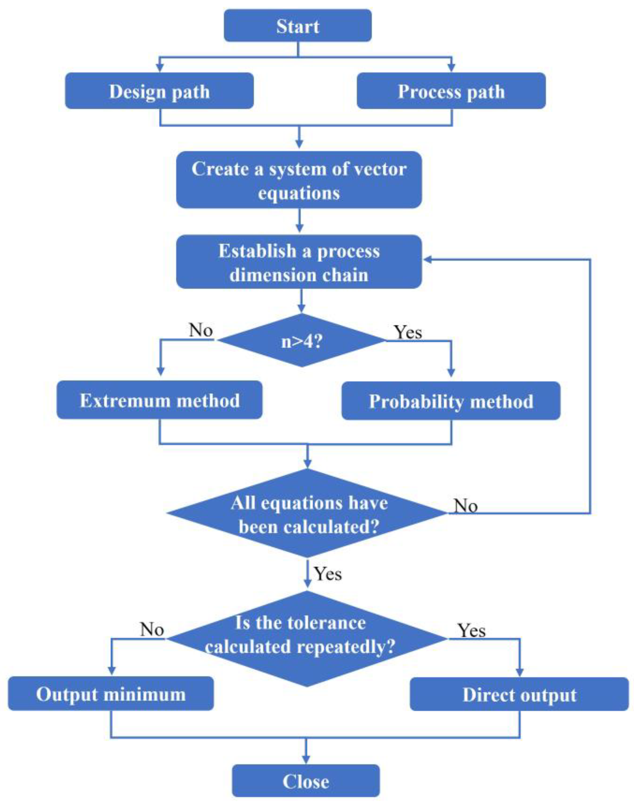
After extracting the data into the dimensional information table, the data in the dimensional information table are analyzed and calculated by combining the contents of the formulas in Section 1. First, a system of vector equations is established according to the design path, and the matrix mathematical model in Section 2.2 is used to calculate the design dimension coordinate dimensions as well as process dimensions. Then, the process dimensional chain is established by the vector equations, the number of loops of the dimensional chain is determined, and the corresponding function is generated according to the corresponding formula in Section 2.3 for the calculation of process dimension tolerance. After calculating all the process dimensional chains, check whether the tolerance of any process dimension has been calculated repeatedly; if so and the results are not equal, select the smallest value as the tolerance of the process dimension. The specific solution process is shown below, as shown in Figure 5:
(1)
Establish a system of equations based on the design path as well as the process path in the dimension information table, and establish the process dimensional chain and dimensional chain equations through the vector equations;
(2)
Determine whether the number of dimensional chain rings is greater than 4, and use Equations (6) and (8) to calculate if it is greater than 4, otherwise use Equations (7) and (8) to calculate;
(3)
Determine whether there are repeated calculations of dimensional tolerances; if so, take the minimum value output to the calculation of the results of the information table; if not, directly output the results to the calculation of the results of the information table.

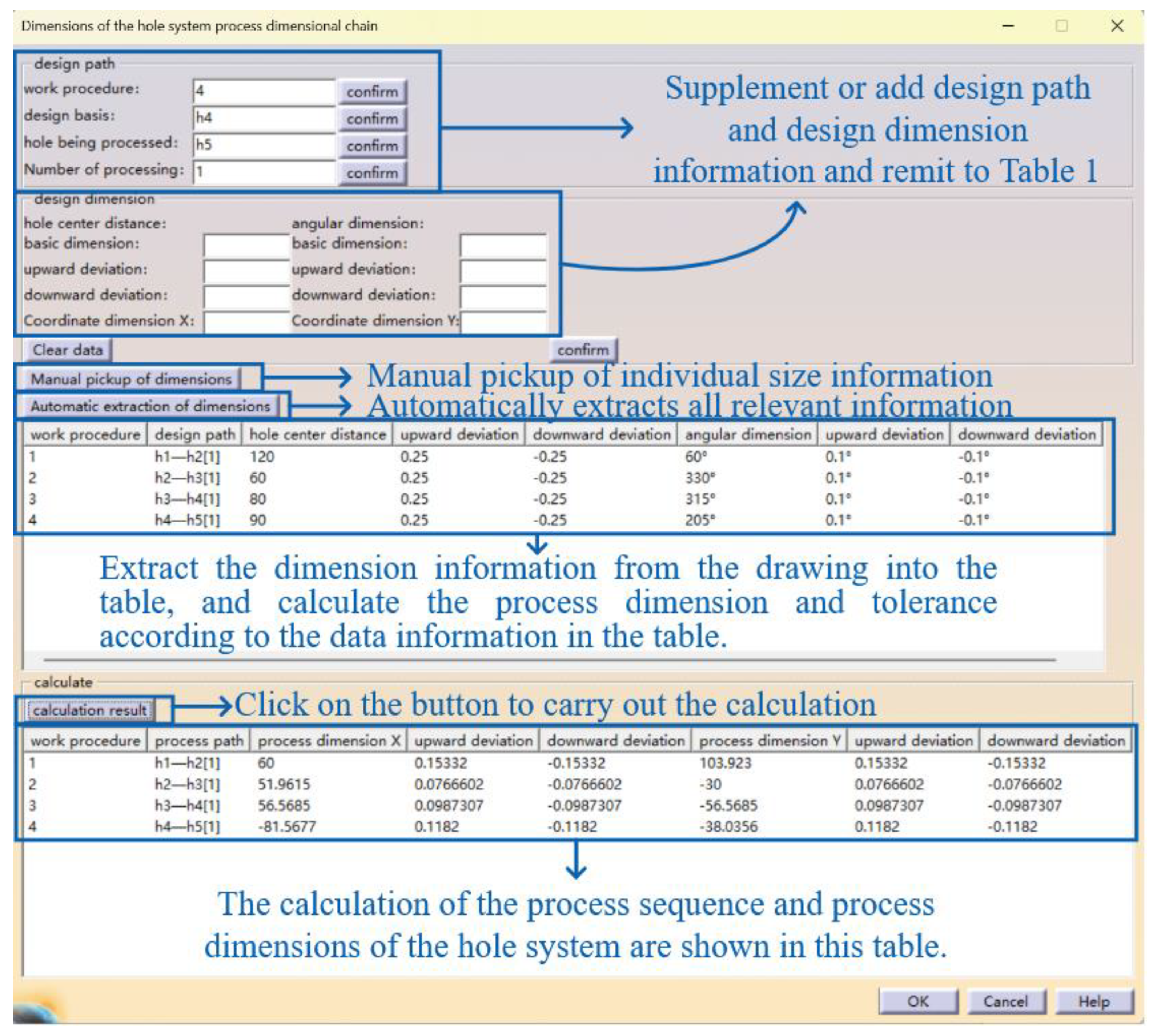
3.3. Interactive Interface Design

The design of the interface of the hole system dimensioning tool is divided into four parts: design path setting, design size setting, design path information table, and process size information table. There are two ways to extract dimension information in this system: manual pickup and automatic pickup. Clicking the manual pickup button will generate the mouse and engineering drawings in response to the selected size in the size information table, but manually picking up the size information requires manually adding the process information and design path; automatic pickup is based on the order of the process, traversing the search for associated dimensions and automatically adding the design path information, and automatically generating the process path all the information which needs to be converted into the design size information table. The interactive interface is shown in Figure 6.

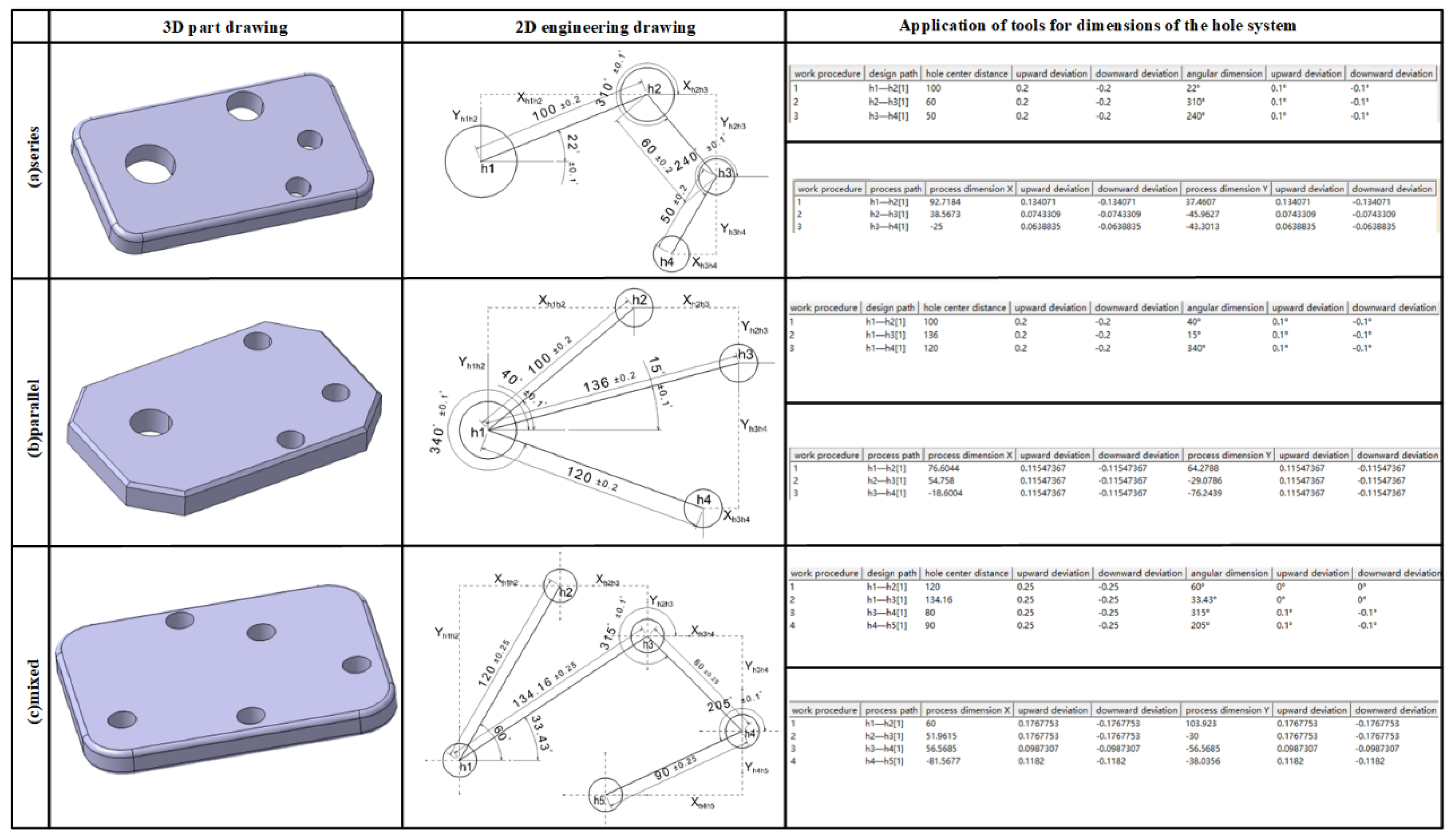
4. Examples of Engineering Applications

The labeling forms of non-orthogonal holes in engineering drawings of porous parts are mainly in series, parallel, and mixed. In order to verify the feasibility of the system, typical examples of the three labeling forms are analyzed separately and compared with the traditional calculation method.

4.1. Example of Calculation

Figure 7 shows the three-dimensional drawing of the porous part and the engineering drawings: the location of each hole is as shown in the engineering drawings, the units of the length dimension shown in the figure are in millimeters (mm), and the units of the angular dimension are degrees (°). Non-orthogonal holes can be labeled in series, parallel, or mixed in three forms; the automatic process dimensioning system is used to analyze and solve the parts shown in Figure 7, as shown in Figure 7a–c.

4.2. Comparison of Results

In order to verify the effectiveness of the hole system dimension analysis tool, this paper compares the calculation results using the traditional method with the results of the automated process dimension calculation system. Using the traditional method to calculate the tolerance using the extremum method formula completely, the comparison of the calculation results is shown in Table 1, Table 2 and Table 3. Dimensions and tolerances in the table are in mm.
According to the calculation results of the hole system dimension analysis tool in Figure 7, it can be seen that the design path in Part (a) is completely overlapped with the process path, the design path in Part (b) is not overlapped with the process path at all, and the design path in Part (c) is partially overlapped with the process path. Comparison of the data in Table 1, Table 2 and Table 3 reveals that when the design path and the process path overlap, the tolerances calculated by hand and by the system are basically the same; when the process path is more different from the design path, the tolerance values obtained by the system will be enlarged by about 50%. According to the hand-calculated and computer-calculated dimensions and tolerances of Part (b) and Part (c), respectively, the qualification rate is calculated, and the results are 95.101%, 94.858%, 95.252%, and 94.903%, respectively. It can be seen that without affecting the pass rate, when the design path does not overlap with the process path, the tolerance value derived from this analysis tool is enlarged by about 50%, which is more in line with the actual situation of production. Moreover, the result of the traditional method can only react to the size relationship, but not the positional relationship between the holes, while the hole system dimension analysis tool can react to the positional relationship between the holes through the positive and negative values of the calculation results.
Computerized calculation takes much less time than manual calculation, which is time-consuming and labor-intensive and produces human errors. The hole system dimension analysis tool greatly improves the efficiency and accuracy, reduces repetitive operations, and improves productivity. This shows that it is feasible and important to develop an automated calculation system for the process dimension of hole system parts.

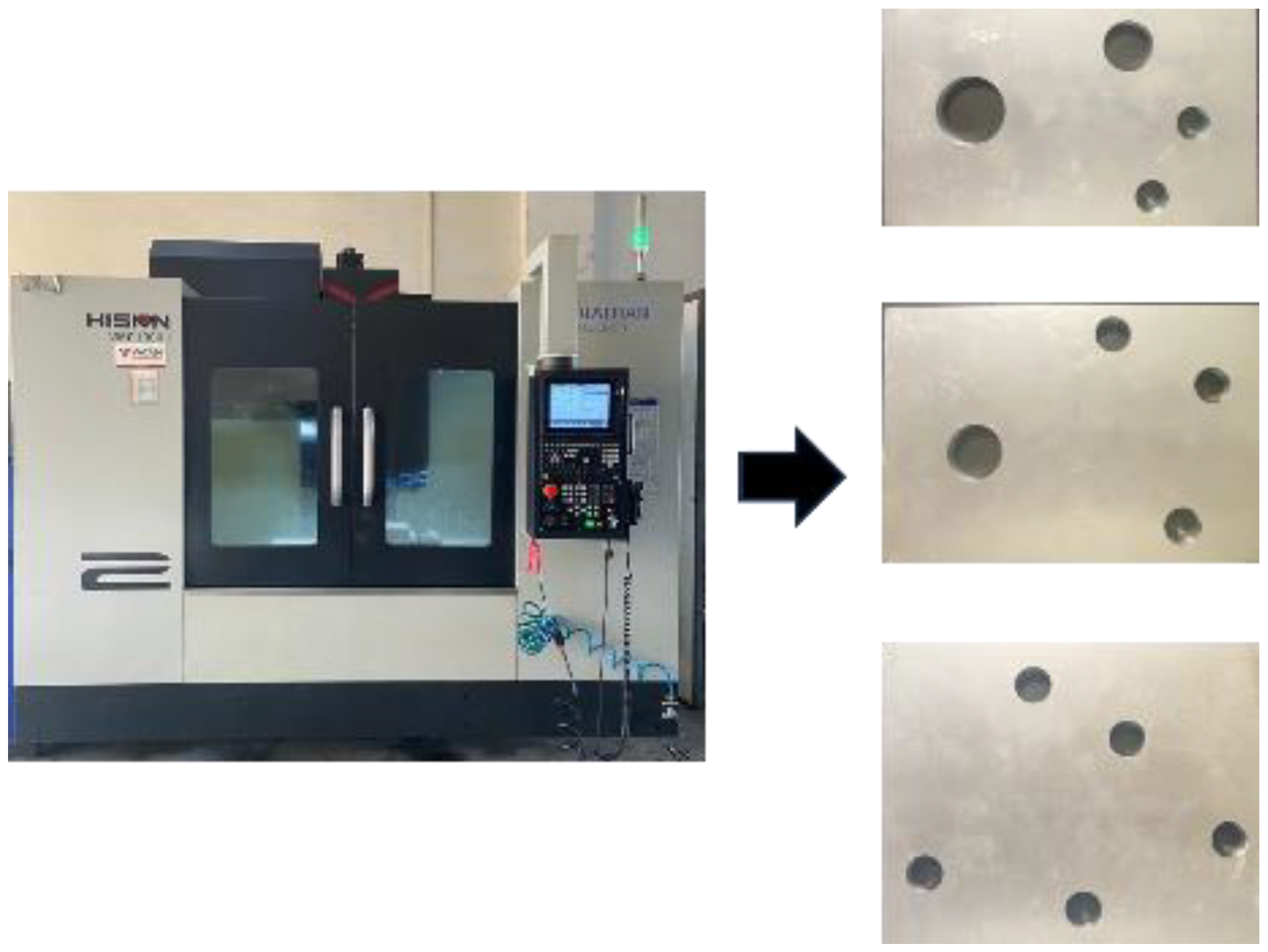
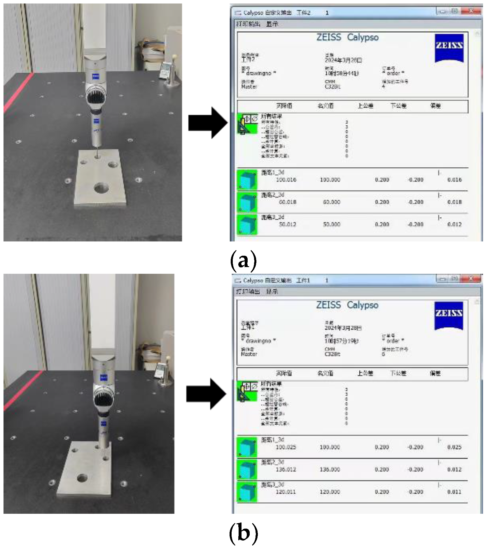
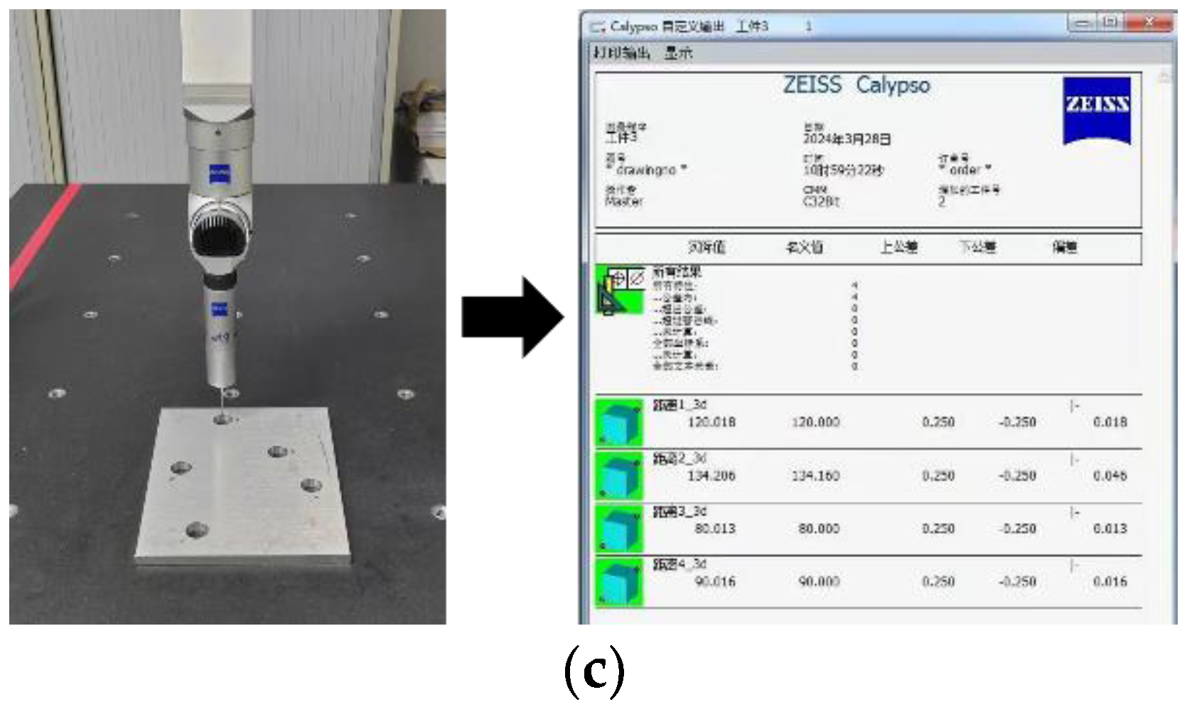
5. Experimental Verification

In order to verify the correctness of the calculation results of this hole system dimension analysis tool, the above three porous parts were machined according to the process dimensions and tolerances calculated by the tool. After the machining was completed, the individual hole center distance of each porous part was measured by a coordinate measuring machine (CMM), the hole center distance in each part was measured precisely, and these measurements were compared and analyzed with the design dimensions specified in the engineering drawings.
According to the data provided by the hole system dimension analysis tool, including the size and tolerance information, the machine is machined by the Haitian CNC1060 machine tool, and the material chosen is 6061T6 aluminum alloy. First, the aluminum alloy plate is fixed using a vacuum suction cup to mill the external dimensions, then all the positioning holes are milled out in one go with an end mill. As shown in Figure 8.
The Zeiss CONTURA Coordinate Measuring Machine (CMM) is a precision instrument that measures in three dimensions to obtain information about the geometry, shape, and position of a workpiece. By moving a probe in three mutually perpendicular axes and using either contact or non-contact sensors to collect data, the CMM can measure the exact position of any point on a workpiece. The measurement data are collected by a displacement measurement system, such as a scale, and processed by computer software in order to calculate the 3D coordinate values of each measurement point and other relevant measurement parameters. In this study, the CMM first measures a reference plane and the software automatically corrects the Z-plane. Next, each hole is measured individually, and the measured circular hole data are projected onto a reference plane, from which the distance between the centers of the individual circular holes is calculated. In this way, the relative positions between holes in a porous part can be measured and analyzed very precisely, thus verifying the accuracy and feasibility of the process dimension analysis tool. We measure the circular holes separately, project the measured circles onto the reference plane, and calculate the distance between the centers.
The hole center distance of the three machined hole parts was measured using a Zeiss CONTURA coordinate measuring machine, and the measurement process and results are shown in Figure 9a–c.
Comparing the measurement results with the design dimensions in the engineering drawings, it can be found that the hole parts machined according to the process dimensions calculated by the hole system dimension analysis tool fully meet the design requirements. The accuracy and effectiveness of the automated system is more clearly demonstrated.

6. Conclusions

To address the problems of low efficiency and the error-prone calculation of process dimensions during the machining of porous parts, this paper carries out the research and development of a tool for analyzing hole system dimensions based on the combination of the process path and the design path. Firstly, a mathematical model is constructed to calculate the process dimensions and tolerances, and then an automated calculation system for process dimensions in the machining of porous parts is established by using CATIA secondary development technology. Finally, the validity and accuracy of the tool was validated:
(1)
Combining the process path with the design path not only expresses the dimensional relationship between two holes, but also describes the machining datum and process sequence between holes. By establishing the mathematical model of process dimension through the process path and design path, all process dimensions with directionality can be solved at once;
(2)
The mathematical model established according to the process path and design path can directly generate the process dimensional chain and dimensional chain calculation function, avoiding the drawing of the dimensional chain and the judgment of the increase and decrease in the ring, simplifying the analysis process and reducing the likelihood of making mistakes. The number of rings in the dimensional chain is determined and different calculation methods are used for the calculation of process dimension tolerance, so that the resulting tolerance is enlarged by about 50%, which is more in line with the actual situation of production and reduces the production cost;
(3)
An automated process dimension calculation tool for porous parts has been developed to make up for the time-consuming and labor-intensive traditional manual calculations, which are prone to errors and need to be repeatedly verified, and to improve the efficiency of the calculations. Therefore, this tool is feasible and significant for analyzing and calculating process dimensions in the machining of complex porous parts;
(4)
Not all users have access to or are proficient in the use of CATIA, and in order to increase the popularity of the tool and broaden its applicability, the development of a stand-alone version of the system will be considered in subsequent studies. This would enable a wider group of users, including those without a background in CATIA, to utilize the tool for design and manufacturing analysis. In addition, the development of a stand-alone version should also be considered to include more flexible interfaces and algorithms to ensure that it can be effectively applied in different design and manufacturing environments.

Author Contributions

Conceptualization, data curation, software, writing—original draft, X.M.; funding acquisition, project administration, J.Y.; review and editing, S.X.; supervision, review and editing, Z.W. All authors have read and agreed to the published version of the manuscript.

Funding

National Key Research and Development Industrial Software (2023YFB3306600).

Data Availability Statement

Data are contained within the article.

Conflicts of Interest

The authors declare no conflicts of interest.

References

  1. Groover, M.P. Fundamentals of Modern Manufacturing: Materials, Processes, and Systems; John Wiley & Sons: Hoboken, NJ, USA, 2020. [Google Scholar]
  2. Hong, Y.S.; Chang, T.C. A comprehensive review of tolerancing research. Int. J. Prod. Res. 2002, 40, 2425–2459. [Google Scholar] [CrossRef]
  3. Meguid, S.A. Integrated Computer-Aided Design of Mechanical Systems; Springer Science & Business Media: Berlin, Germany, 1987. [Google Scholar]
  4. Xue, J.; Ji, P. Process tolerance allocation in angular tolerance charting. Int. J. Prod. Res. 2004, 42, 3929–3945. [Google Scholar] [CrossRef]
  5. González Contreras, F.; Rosado, P. An alternative method to tolerance transfer for parts with 2D blueprint. Int. J. Prod. Res. 2007, 45, 5309–5328. [Google Scholar] [CrossRef]
  6. Ji, P.; Xue, J.B. Process tolerance control in a 2D angular tolerance chart. Int. J. Adv. Manuf. Technol. 2002, 20, 649–654. [Google Scholar] [CrossRef]
  7. Li, K.L.; Wang, Z.Y.; Li, J.F.; Geng, J. The parallel-chain in the machining-process-dimension-chain and application. Appl. Mech. Mater. 2008, 10, 615–620. [Google Scholar] [CrossRef]
  8. Ji, P.; Xue, J. Extending the algebraic method to identify dimensional chains for angular tolerance charting. Int. J. Prod. Res. 2002, 40, 1597–1612. [Google Scholar] [CrossRef]
  9. Pan, Y.R.; Tang, G.R. Computer-aided tolerance charting for products with angular features. Int. J. Adv. Manuf. Technol. 2001, 17, 361–370. [Google Scholar] [CrossRef]
  10. Masyagin, V.; Bazhenov, R.; Artyukh, R. Calculation of linear technological dimensions with adaptation. MATEC Web Conf. 2018, 224, 01072. [Google Scholar] [CrossRef]
  11. Pang, L.; Liu, Y.; Fu, R.; Ji, L.; Li, Y. Research on the method of UG secondary development to the calculating plane dimension chain. In Proceedings of the 2nd International Conference on Electronic & Mechanical Engineering and Information Technology, Shenyang, China, 7 September 2012; pp. 1534–1537. [Google Scholar]
  12. Ji, L.; Liu, L.Q.; Mei, X.F. Calculation of dimension chain through AutoCAD secondary development technique based on dimension tracking method. Appl. Mech. Mater. 2012, 101, 631–634. [Google Scholar] [CrossRef]
  13. Lin, Y.H.; Ting, Y.H.; Huang, Y.C.; Cheng, K.L.; Jong, W.R. Integration of Deep Learning for Automatic Recognition of 2D Engineering Drawings. Machines 2023, 11, 802. [Google Scholar] [CrossRef]
  14. Jiang, N.; Wang, S.; Yang, A.; Zhou, W.; Zhang, J. Transmission Efficiency of Cycloid–Pinion System Considering the Assembly Dimensional Chain. Appl. Sci. 2022, 12, 11917. [Google Scholar] [CrossRef]
  15. Dong, Y.; Su, F.; Sun, G.; Liu, Y.; Zhang, F. A feature-based method for tire pattern reverse modeling. Adv. Eng. Softw. 2018, 124, 73–89. [Google Scholar] [CrossRef]
  16. Yougao, F.; Xiaoyu, D.; Jianhua, L.; Zhiqiang, Z. A method of automatic generation of assembly dimension chains based on information cells. J. Comput. Aided Des. Comput. Graph. 2016, 28, 1989–1999. [Google Scholar]
  17. Fang, H.M.; Zhao, G.; Zhang, G.Z.; Xiao, P. The Research and the Development of the 3D System Platform of Shafting Parts Based on CAA. Key Eng. Mater. 2016, 693, 1886–1892. [Google Scholar] [CrossRef]
  18. Zhang, G.G.; Chang, Z.B.; Liu, H.T. Parametric modeling for globoidal cam based on CATIA/CAA. Appl. Mech. Mater. 2011, 88, 236–239. [Google Scholar] [CrossRef]
  19. Shen, Z.; Ameta, G.; Shah, J.J.; Davidson, J.K. A comparative study of tolerance analysis methods. In Proceedings of the International Design Engineering Technical Conferences and Computers and Information in Engineering Conference, Long Beach, CA, USA, 24–28 September 2005. [Google Scholar]
  20. Li, K. Dimension Chain of Machining Process; National Defense Industry Press: Beijing, China, 2008. [Google Scholar]
  21. Chahbouni, M.; Elmouden, M.; Miskin, M.; Boutahari, S.; Amegouz, D. Tolerance analysis with the 1D angular dimension chain: Application. In Proceedings of the 2020 IEEE 13th International Colloquium of Logistics and Supply Chain Management (LOGISTIQUA), Fez, Morocco, 2–4 December 2020; pp. 1–6. [Google Scholar]
  22. Hu, B.; Wu, Y. CATIA Software Modeling and Secondary Development of CAA Beijing; Beijing University of Aeronautics and Astronautics Press: Beijing, China, 2018; pp. 75–82. [Google Scholar]
  23. Bao, J.R.; Ding, Y.; Hu, S.B.; Hu, P. A study on intelligent parting line design of vehicle door based on CATIA CAA. Adv. Mater. Res. 2014, 902, 357–363. [Google Scholar] [CrossRef]
  24. Hao, B.; Liu, F.; Liu, M. Variant design of typical aircraft parts based on CATIA technology. J. Phys. Conf. Ser. 2020, 1605, 012064. [Google Scholar] [CrossRef]
Figure 1. Thesis research framework.
Machines 12 00245 g001
Figure 2. Pore system relations of porous part.
Machines 12 00245 g002
Figure 3. Design path and process path.
Machines 12 00245 g003
Figure 4. Establishment of coordinate system.
Machines 12 00245 g004
Figure 5. Calculation flow chart.
Machines 12 00245 g005
Figure 6. The interactive interface of the hole system size analysis tool.
Machines 12 00245 g006
Figure 7. Example of calculation with the hole system dimension analysis tool.
Machines 12 00245 g007
Figure 8. Haitian CNC 1060 machine tool and porous part (Haitian Precision, Ningbo, China).
Machines 12 00245 g008
Figure 9. Measuring the center distance of holes with CMC. (Carl Zeiss AG, Oberkochen, Germany).
Machines 12 00245 g009aMachines 12 00245 g009b
Table 1. Process size data comparison of Part (a).
Dimensions and TolerancesTraditional MethodProposed Method
X h 1 h 2 92.72 ± 0.13407192.72 ± 0.134071
Y h 1 h 2 37.46 ± 0.13407137.4607± 0.134071
X h 2 h 3 38.57 ± 0.0743338.5673 ± 0.0743309
Y h 2 h 3 45.96 ± 0.07433−45.9627 ± 0.0743309
X h 3 h 4 25 ± 0.06388−25 ± 0.0638835
Y h 3 h 4 43.30 ± 0.06388−43.3013 ± 0.0638835
Table 2. Process size data comparison of Part (b).
Dimensions and TolerancesTraditional MethodProposed Method
X h 1 h 2 76.60 ± 0.05201676.6044 ± 0.11547367
Y h 1 h 2 64.28 ± 0.05201664.2788 ± 0.11547367
X h 2 h 3 54.758 ± 0.05201654.758 ± 0.11547367
Y h 2 h 3 29.08 ± 0.052016−29.0786 ± 0.11547367
X h 3 h 4 18.60 ± 0.052016−18.6004 ± 0.11547367
Y h 3 h 4 76.24 ± 0.052016−76.2439 ± 0.11547367
Table 3. Process size data comparison of Part (c).
Dimensions and Tolerances Traditional MethodProposed Method
X h 1 h 2 60 ± 0.09021860 ± 0.17677531
Y h 1 h 2 103.92 ± 0.090218103.923 ± 0.17677531
X h 2 h 3 51.96 ± 0.09021851.6915 ± 0.17677531
Y h 2 h 3 30 ± 0.090218−30 ± 0.17677531
X h 3 h 4 56.57 ± 0.098730756.5685 ± 0.0987307
Y h 3 h 4 56.57 ± 0.0987307−56.5685 ± 0.0987307
X h 4 h 5 81.57 ± 0.1182−81.5677 ± 0.1182
Y h 4 h 5 38.04 ± 0.1182−38.0356 ± 0.1182
Disclaimer/Publisher’s Note: The statements, opinions and data contained in all publications are solely those of the individual author(s) and contributor(s) and not of MDPI and/or the editor(s). MDPI and/or the editor(s) disclaim responsibility for any injury to people or property resulting from any ideas, methods, instructions or products referred to in the content.

